EP4382436A1 - Bagmaking and packaging apparatus - Google Patents
Bagmaking and packaging apparatus Download PDFInfo
- Publication number
- EP4382436A1 EP4382436A1 EP23214131.7A EP23214131A EP4382436A1 EP 4382436 A1 EP4382436 A1 EP 4382436A1 EP 23214131 A EP23214131 A EP 23214131A EP 4382436 A1 EP4382436 A1 EP 4382436A1
- Authority
- EP
- European Patent Office
- Prior art keywords
- bagmaking
- packaging apparatus
- disposed
- support post
- tube
- Prior art date
- Legal status (The legal status is an assumption and is not a legal conclusion. Google has not performed a legal analysis and makes no representation as to the accuracy of the status listed.)
- Granted
Links
Images





Classifications
-
- B—PERFORMING OPERATIONS; TRANSPORTING
- B65—CONVEYING; PACKING; STORING; HANDLING THIN OR FILAMENTARY MATERIAL
- B65B—MACHINES, APPARATUS OR DEVICES FOR, OR METHODS OF, PACKAGING ARTICLES OR MATERIALS; UNPACKING
- B65B9/00—Enclosing successive articles, or quantities of material, e.g. liquids or semiliquids, in flat, folded, or tubular webs of flexible sheet material; Subdividing filled flexible tubes to form packages
- B65B9/10—Enclosing successive articles, or quantities of material, in preformed tubular webs, or in webs formed into tubes around filling nozzles, e.g. extruded tubular webs
- B65B9/20—Enclosing successive articles, or quantities of material, in preformed tubular webs, or in webs formed into tubes around filling nozzles, e.g. extruded tubular webs the webs being formed into tubes in situ around the filling nozzles
-
- B—PERFORMING OPERATIONS; TRANSPORTING
- B65—CONVEYING; PACKING; STORING; HANDLING THIN OR FILAMENTARY MATERIAL
- B65B—MACHINES, APPARATUS OR DEVICES FOR, OR METHODS OF, PACKAGING ARTICLES OR MATERIALS; UNPACKING
- B65B9/00—Enclosing successive articles, or quantities of material, e.g. liquids or semiliquids, in flat, folded, or tubular webs of flexible sheet material; Subdividing filled flexible tubes to form packages
- B65B9/10—Enclosing successive articles, or quantities of material, in preformed tubular webs, or in webs formed into tubes around filling nozzles, e.g. extruded tubular webs
- B65B9/20—Enclosing successive articles, or quantities of material, in preformed tubular webs, or in webs formed into tubes around filling nozzles, e.g. extruded tubular webs the webs being formed into tubes in situ around the filling nozzles
- B65B9/207—Enclosing successive articles, or quantities of material, in preformed tubular webs, or in webs formed into tubes around filling nozzles, e.g. extruded tubular webs the webs being formed into tubes in situ around the filling nozzles the web advancing continuously
-
- B—PERFORMING OPERATIONS; TRANSPORTING
- B65—CONVEYING; PACKING; STORING; HANDLING THIN OR FILAMENTARY MATERIAL
- B65B—MACHINES, APPARATUS OR DEVICES FOR, OR METHODS OF, PACKAGING ARTICLES OR MATERIALS; UNPACKING
- B65B41/00—Supplying or feeding container-forming sheets or wrapping material
- B65B41/12—Feeding webs from rolls
-
- B—PERFORMING OPERATIONS; TRANSPORTING
- B65—CONVEYING; PACKING; STORING; HANDLING THIN OR FILAMENTARY MATERIAL
- B65B—MACHINES, APPARATUS OR DEVICES FOR, OR METHODS OF, PACKAGING ARTICLES OR MATERIALS; UNPACKING
- B65B51/00—Devices for, or methods of, sealing or securing package folds or closures; Devices for gathering or twisting wrappers, or necks of bags
- B65B51/10—Applying or generating heat or pressure or combinations thereof
- B65B51/26—Devices specially adapted for producing transverse or longitudinal seams in webs or tubes
- B65B51/30—Devices, e.g. jaws, for applying pressure and heat, e.g. for subdividing filled tubes
- B65B51/306—Counter-rotating devices
-
- B—PERFORMING OPERATIONS; TRANSPORTING
- B65—CONVEYING; PACKING; STORING; HANDLING THIN OR FILAMENTARY MATERIAL
- B65B—MACHINES, APPARATUS OR DEVICES FOR, OR METHODS OF, PACKAGING ARTICLES OR MATERIALS; UNPACKING
- B65B57/00—Automatic control, checking, warning, or safety devices
- B65B57/005—Safety-devices
-
- B—PERFORMING OPERATIONS; TRANSPORTING
- B65—CONVEYING; PACKING; STORING; HANDLING THIN OR FILAMENTARY MATERIAL
- B65B—MACHINES, APPARATUS OR DEVICES FOR, OR METHODS OF, PACKAGING ARTICLES OR MATERIALS; UNPACKING
- B65B59/00—Arrangements to enable machines to handle articles of different sizes, to produce packages of different sizes, to vary the contents of packages, to handle different types of packaging material, or to give access for cleaning or maintenance purposes
- B65B59/04—Machines constructed with readily-detachable units or assemblies, e.g. to facilitate maintenance
-
- B—PERFORMING OPERATIONS; TRANSPORTING
- B65—CONVEYING; PACKING; STORING; HANDLING THIN OR FILAMENTARY MATERIAL
- B65B—MACHINES, APPARATUS OR DEVICES FOR, OR METHODS OF, PACKAGING ARTICLES OR MATERIALS; UNPACKING
- B65B65/00—Details peculiar to packaging machines and not otherwise provided for; Arrangements of such details
- B65B65/003—Packaging lines, e.g. general layout
Definitions
- the present invention relates to a bagmaking and packaging apparatus.
- Bagmaking and packaging apparatus such as disclosed in patent document 1 ( JP-A No. 2002-337817 ) are known which perform bagmaking and packaging by feeding product from above to the inside of a tubular film, in which a film has been formed in a tubular shape, and transversely sealing tops and bottoms of the tubular film.
- a bagmaking and packaging apparatus pertaining to a first aspect of the invention performs bagmaking and packaging.
- the bagmaking and packaging apparatus comprises a film supply unit, a former mechanism, a transverse sealing mechanism, plural support posts.
- the film supply unit is disposed in a rear portion of the bagmaking and packaging apparatus.
- the film supply unit is configured to supply sheet-like film.
- the former mechanism includes a former and a tube.
- the former mechanism is disposed forward of a film supply unit.
- the former mechanism is configured to form in a tubular shape the sheet-like film supplied from the film supply unit.
- the transverse sealing mechanism is configured to transversely seal the tubular film in which a product is supplied from above.
- the plural support posts configure a frame that surrounds at least part of each of the film supply unit, the former mechanism, and the transverse sealing mechanism.
- the plural support posts include a first support post group and a second support post group.
- the first support post group and the second support post group each includes a plurality of the support posts.
- the support posts of the first support post group are disposed on one lateral side of the bagmaking and packaging apparatus in a left and right direction
- the support posts of the second support post group are disposed on the other lateral side of the bagmaking and packaging apparatus in the left and right direction.
- a first support post disposed foremost among the support posts of the first support post group extends from a low position to a position higher than the transverse sealing mechanism and, when viewed from above, is disposed forward of a center of the tube.
- a second support post disposed foremost among the support posts of the second support post group extends from a low position to a position higher than the transverse sealing mechanism and, when viewed from above, is disposed rearward of the center of the tube.
- the second support post is disposed in the above-described position, maintenance space can be ensured on the side of the bagmaking and packaging apparatus in the left and right direction where the second support post group is disposed while inhibiting an increase in the size of the bagmaking and packaging apparatus.
- the first support post is disposed in the above-described position.
- various devices and parts of the bagmaking and packaging apparatus can be solidly supported.
- a bagmaking and packaging apparatus pertaining to a second aspect of the invention is the bagmaking and packaging apparatus of the first aspect, wherein the first support post is disposed forward of the tube.
- the heavy object can be solidly supported and vibration of the bagmaking and packaging apparatus can be inhibited.
- a bagmaking and packaging apparatus pertaining to a third aspect of the invention is the bagmaking and packaging apparatus of the first aspect or the second aspect, wherein the second support post is disposed rearward of the tube.
- the bagmaking and packaging apparatus of the third aspect it is easy to ensure sufficient work space around the former mechanism. For example, when replacing the former mechanism, movement of the former mechanism is less likely to be obstructed by the second support post.
- a bagmaking and packaging apparatus pertaining to a fourth aspect of the invention is the bagmaking and packaging apparatus of any of the first aspect to the third aspect, wherein the first support post supports a member disposed above the former mechanism.
- a heavy object such as a metal detector that detects metal contaminants in the supplied product is disposed above the former mechanism. If such a heavy object is disposed in the upper portion of the bagmaking and packaging apparatus and both the first support post and the second support post are disposed rearward of the center of the tube, there is the risk that the balance in the support will be upset, resulting in a deterioration in the installation stability of the bagmaking and packaging apparatus.
- the bagmaking and packaging apparatus of the fourth aspect has the first support post disposed in the above-described position, even if such a heavy object is present, the heavy object can be solidly supported by the frame.
- a bagmaking and packaging apparatus pertaining to a fifth aspect of the invention is the bagmaking and packaging apparatus of any of the first aspect to the fourth aspect, further including a cover that covers at least a front side of the former mechanism.
- the first support post supports the cover.
- a cover that covers the former mechanism is installed from the standpoint of safety and hygiene.
- a cover can be solidly supported by the first support post disposed in the above-described position.
- a bagmaking and packaging apparatus pertaining to a sixth aspect of the invention is the bagmaking and packaging apparatus of any of the first aspect to the fifth aspect, wherein the first support post supports a movable member.
- the bagmaking and packaging apparatus When the bagmaking and packaging apparatus is provided with a movable member (a member driven to move by a drive unit), vibration may occur as a result of the movable member moving.
- a movable member a member driven to move by a drive unit
- the bagmaking and packaging apparatus of the sixth aspect has the first support post disposed in the above-described position and the stability of the frame is high, even if a movable member that causes vibration is present, vibration of the bagmaking and packaging apparatus can be reliably inhibited.
- a balance between stable support of various devices and parts of the bagmaking and packaging apparatus and high maintainability can be achieved while inhibiting an increase in the apparatus size.
- a bagmaking and packaging apparatus 100 that is an embodiment of the bagmaking and packaging apparatus of the present invention will be described with reference to the drawings. It will be noted that the following embodiment is merely a specific example of the invention and is not intended to limit the technical scope of the invention.
- expressions such as perpendicular, orthogonal, horizontal, and vertical may be sometimes used to describe directions and positional relationships, but these expressions are not limited to their strict senses and include cases where that which they describe are substantially perpendicular, orthogonal, horizontal, or vertical.
- expressions such as front, rear, above, below, left, and right are used to indicate directions and such. Unless otherwise specified, front, rear, above, under, left, and right here follow the directions of the arrows added to the drawings.
- the side where a later-described film supply unit 300 is disposed as viewed from the position of a later-described bagmaking and packaging unit 200 will be defined as the rear, and the side where the bagmaking and packaging unit 200 is disposed as viewed from the position of the film supply unit 300 will be defined as the front.
- a direction that is a horizontal direction and orthogonal to the front and rear direction in which the bagmaking and packaging unit 200 and the film supply unit 300 are lined up will be defined as the left and right direction.
- FIG. 1 is a schematic perspective view of the packaging and inspection system 1 including the bagmaking and packaging apparatus 100.
- FIG. 2 is a schematic perspective view of the bagmaking and packaging apparatus 100.
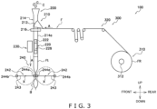
- FIG. 3 is a diagram showing the schematic configuration of the bagmaking and packaging apparatus 100.
- FIG. 2 illustrates a state in which a later-described door 582 disposed in the front upper portion of the bagmaking and packaging apparatus 100 is open and a protective plate 590 (see FIG. 1 ) disposed in the front lower portion of the bagmaking and packaging apparatus 100 is detached. Furthermore, FIG. 2 illustrates a state in which, for the purpose of maintenance or the like, a later-described former mechanism 210 and longitudinal sealing mechanism 230 have been moved from the positions they are in when the bagmaking and packaging apparatus 100 is operating.
- the packaging and inspection system 1 mainly includes the bagmaking and packaging apparatus 100, a conveyance apparatus 2, and a seal checker 3.
- the bagmaking and packaging apparatus 100 makes a bag-like packaging material from a sheet-like film F to thereby make bags B containing a product C inside (see FIG. 3 ).
- the product C to be contained in the bags B is supplied to the bagmaking and packaging apparatus 100 from a combination weigher (not shown in the drawings) disposed above the bagmaking and packaging apparatus 100.
- the bags B made by the bagmaking and packaging apparatus 100 are conveyed by the conveyance apparatus 2.
- the seal checker 3 checks the seals of the bags B (whether or not the bags B are airtight) conveyed by the conveyance apparatus 2.
- the combination weigher uses multiple weigh hoppers to measure weights of the product C, combines weigh values obtained by the multiple weigh hoppers so that the total weight thereof is in a predetermined weight range, and drops the product C for which the total combined weight is within the predetermined weight range to thereby supply it to the bagmaking and packaging apparatus 100.
- the conveyance apparatus 2 is a conveyor extending forward from below a transverse sealing mechanism 240 of the bagmaking and packaging apparatus 100.
- the conveyance apparatus 2 conveys forward the bags B made by the bagmaking and packaging apparatus 100 and transfers them to a process downstream of the packaging and inspection system 1 (e.g., a conveyor that conveys the bags B to a box packing apparatus).
- the bagmaking and packaging apparatus 100 mainly includes a film supply unit 300, a bagmaking and packaging unit 200, a metal inspection device 400, a frame 500, and a control device (such as computer, control board and PLC not shown in the drawings).
- the film supply unit 300 is disposed in the rear portion of the bagmaking and packaging apparatus 100.
- the film supply unit 300 supplies the sheet-like film F to the bagmaking and packaging unit 200 disposed forward of the film supply unit 300.
- the bagmaking and packaging unit 200 is disposed in the front portion of the bagmaking and packaging apparatus 100.
- the bagmaking and packaging unit 200 forms the sheet-like film F in a tubular shape and transversely seals the film F formed in the tubular shape (a tubular film Ft) to make the bags B.
- the metal inspection device 400 inspects for contaminants (metal) in the product C dropped and supplied from the combination weigher (not shown in the drawings) to the bagmaking and packaging apparatus 100.
- the frame 500 mainly supports the film supply unit 300, the bagmaking and packaging unit 200, and the metal inspection device 400.
- the control device controls the operation of each part of the film supply unit 300 and the bagmaking and packaging unit 200 and performs various calculations and processes.
- the bagmaking and packaging apparatus 100 will now be described in detail.
- the film supply unit 300 is disposed in the rear portion of the bagmaking and packaging apparatus 100.
- the film supply unit 300 is disposed rearward of the bagmaking and packaging unit 200 and next to the bagmaking and packaging unit 200.
- the film supply unit 300 supplies the sheet-like film F to a later-described former mechanism 210 of the bagmaking and packaging unit 200 disposed forward of the film supply unit 300.
- the film supply unit 300 mainly includes a film roll support mechanism 310 and a guide mechanism 320.
- the film roll support mechanism 310 holds a film roll FR in which the sheet-like film F is wound about a core (not shown in the drawings).
- the film roll support mechanism 310 uses a drive unit such as a motor (not shown in the drawings) to rotate a shaft 312 to which the core of the film roll FR is attached (see FIG. 1 to FIG. 3 ) and pay out the film F from the film roll FR.
- the guide mechanism 320 includes plural rollers disposed along a conveyance path of the film F.
- the guide mechanism 320 guides to the former mechanism 210 of the bagmaking and packaging unit 200 the film F paid out from the film roll FR.
- the bagmaking and packaging unit 200 mainly includes a former mechanism 210, a conveyance mechanism 220, a longitudinal sealing mechanism 230, and a transverse sealing mechanism 240.
- the former mechanism 210 mainly includes a former 212, a tube 214, a plate 216, and a grip unit 218.
- the former 212 is disposed so as to surround the tubular tube 214 and forms in a tubular shape the sheet-like film F conveyed thereto from the film supply unit 300 disposed in the rear portion of the bagmaking and packaging apparatus 100 by bending the film F so that left and right end portions of the film F in the width direction overlap each other.
- the tubular film Ft formed by the former 212 is guided so as to become wrapped around the outer peripheral surface of the lower portion of the tubular tube 214 and is conveyed downward in a state in which it is wrapped around the tube 214.
- the portion of the tube 214 around which the tubular film Ft is wrapped is sometimes called the portion 214a.
- the tube 214 is a tubular member that extends in the vertical direction and has upper and lower end portions that are open.
- the lower end of the tube 214 is disposed higher than the transverse sealing mechanism 240 (higher than areas where later-described rotating bodies 242 of the transverse sealing mechanism 240 rotate) so as not to hinder the movement of the rotating bodies 242.
- the tube 214 receives the falling product C in the upper opening of the tube 214 and supplies, from the lower opening of the tube 214 to the inside of the tubular film Ft, the product C fed through the upper opening.
- the plate 216 is mounted on and secured to a mount (not shown in the drawings) supported by the frame 500, and is supported by the frame 500 via the mount.
- the former 212 and the tube 214 are attached to the plate 216 directly or via another member, and the plate 216 supports the former 212 and the tube 214.
- the grip unit 218 is attached to the plate 216 directly or via another member.
- the conveyance mechanism 220 is disposed under the plate 216 of the former mechanism 210.
- the conveyance mechanism 220 is disposed on the left and right sides of the portion 214a of the tube 214 around which the tubular film Ft is wrapped.
- the conveyance mechanism 220 conveys to the former mechanism 210 the film F paid out from the film roll FR and conveys to the transverse sealing mechanism 240 the tubular film Ft formed by the former 212.
- the conveyance mechanism 220 has pull-down belts 226 having a suction function, and the conveyance mechanism 220 conveys the tubular film Ft downward as a result of drive rollers 222 around which the pull-down belts 226 are entrained being driven by a drive mechanism such as a motor (not shown in the drawings) in a state in which the pull-down belts 226 are sucking hold the film F.
- a drive mechanism such as a motor (not shown in the drawings) in a state in which the pull-down belts 226 are sucking hold the film F.
- the longitudinal sealing mechanism 230 seals the overlapping portion of the tubular film Ft at which the left and right end portions of the tubular film Ft overlap each other.
- the longitudinal sealing mechanism 230 is disposed in front of a path on which is conveyed the overlapping portion of the tubular film Ft, which is conveyed in a state in which the tubular film Ft is wrapped around the tube 214.
- the longitudinal sealing mechanism 230 has a built-in heater (not shown in the drawings) inside. When the longitudinal sealing mechanism 230 with its heater turned on is driven by a drive unit (not shown in the drawings) so that the longitudinal sealing mechanism 230 is pressed against the tube 214 via the tubular film Ft, the overlapping portion of the tubular film Ft is sealed in the up and down direction (the longitudinal direction).
- the transverse sealing mechanism 240 is disposed below the longitudinal sealing mechanism 230.
- the transverse sealing mechanism 240 transversely seals the top and bottom of a segment of the tubular film Ft corresponding to one bag B (used to make one bag B) to make a bag B containing the product C.
- the transverse sealing mechanism 240 transversely seals, in a direction orthogonal to a conveyance direction A of the tubular film Ft, the longitudinally sealed tubular film Ft conveyed downward by the conveyance mechanism 220 to thereby form transverse seal portions of the bag B.
- the transverse sealing mechanism 240 mainly includes a pair of rotating bodies 242 disposed in front of and in back of the tubular film Ft.
- Each rotating body 242 includes an arm 243 that is configured to be rotatable about an axis of rotation X and sealing jaws 244a, 244b that are attached to the arm 243 and have built-in heaters.
- the sealing jaws 244a of both rotating bodies 242 function as a pair to transversely seal the tubular film Ft.
- the sealing jaws 244b of both rotating bodies 242 also function as a pair to transversely seal the tubular film Ft.
- the pair of sealing jaws 244a and the pair of sealing jaws 244b alternatingly transversely seal the tubular film Ft conveyed thereto.
- One of the pair of sealing jaws 244a and one of the pair of sealing jaws 244b are each provided with a cutter (not illustrated), and the transverse sealing mechanism 240 cuts the transversely sealed portion in a direction orthogonal to the conveyance direction A of the tubular film Ft to thereby cut the bag B away from the trailing tubular film Ft at the timing when the pair of sealing jaws 244a perform heat sealing or at the timing when the pair of sealing jaws 244b perform heat sealing.
- the metal inspection device 400 is disposed above the upper end of the tube 214 of the former mechanism 210. In other words, the metal inspection device 400 is disposed above the former mechanism 210. In particular, here, the metal inspection device 400 is disposed directly above the former mechanism 210. At least part of the metal inspection device 400 is disposed forward of a center O of the tube 214. A definition for the center O of the tube 214 will be given later.
- the metal inspection device 400 inspects for contaminants (metal) in the product C dropped and supplied from the combination weigher to the opening in the upper end of the tube 214.
- the metal inspection device 400 is supported by the frame 500.
- the metal inspection device 400 itself is a known device, so detailed description thereof will be omitted.
- FIG. 4A is a schematic plan view illustrating the arrangement of support posts 510 of the frame 500 of the bagmaking and packaging apparatus 100.
- FIG. 4B is a schematic right side view illustrating the arrangement of the support posts 510 of the frame 500 of the bagmaking and packaging apparatus 100. It will be noted that in FIG. 4A and FIG. 4B hatching is added to the support posts 510 from the standpoint of facilitating understanding of the drawings.
- the frame 500 supports various devices and parts of the film supply unit 300, various devices and parts of the bagmaking and packaging unit 200, and the metal inspection device 400 of the bagmaking and packaging apparatus 100.
- the frame 500 includes, for example, plural upright support posts 510 and beams that bridge the support posts 510.
- the frame 500 is configured by, for example, the support posts 510 and the beams.
- the support posts 510 which are the characteristic configuration of the bagmaking and packaging apparatus 100, will be mainly described.
- the frame 500 having the plural support posts 510 surrounds at least part of each of the film supply unit 300, the former mechanism 210, and the transverse sealing mechanism 240.
- the recitation that the frame 500 surrounds at least part of the film supply unit 300 means that, when viewed from above, at least part of the film supply unit 300 is disposed in an area (in the rectangle in FIG. 4A ) defined by a virtual line extending in the left and right direction and passing through the support post 510 disposed foremost, a virtual line extending in the left and right direction and passing through the support posts 510 disposed rearmost, a virtual line extending in the front and rear direction and passing through the support posts 510 disposed rightmost, and a virtual line extending in the front and rear direction and passing through the support posts 510 disposed leftmost.
- the meanings of the recitation that the frame 500 surrounds at least part of the former mechanism 210 and the recitation that the frame 500 surrounds at least part of the transverse sealing mechanism 240 are similarly defined.
- the plural support posts 510 include a first support post group 220 including a plurality of the support posts 510 disposed on one lateral side of the bagmaking and packaging apparatus 100 in the left and right direction (relative to a virtual line K extending in the front and rear direction through the left and right direction center of the bagmaking and packaging apparatus 100) and a second support post group 530 including a plurality of the support posts 510 disposed on the other lateral side in the left and right direction (see FIG. 4A ).
- the support posts 510 included in the first support post group 520 are disposed on the left side in the bagmaking and packaging apparatus 100.
- the support posts 510 included in the second support post group 530 are disposed on the right side in the bagmaking and packaging apparatus 100.
- first support post group 520 and the second support post group 530 is merely an example, and the first support post group 520 having later-described characteristics may be disposed on the right side in the bagmaking and packaging apparatus 100 and the second support post group 520 having later-described characteristics may be disposed on the left side in the bagmaking and packaging apparatus 100.
- the plural support posts 510 are arranged asymmetrically relative to the virtual line K extending through the left and right direction center of the bagmaking and packaging apparatus 100.
- a first support post 522 disposed foremost among the support posts 510 of the first support post group 520 is disposed forward of the center O of the tube 214 (forward of a virtual line L passing through the center O) when viewed from above. More preferably, the first support post 522 is disposed forward of the tube 214 (in particular, here, the portion 214a of the tube 214 around which the tubular film Ft formed in the tubular shape by the former 212 is wrapped).
- a second support post 532 disposed foremost among the support posts 510 of the second support post group 530 is disposed rearward of the center O of the tube 214 (rearward of the virtual line L passing through the center O) when viewed from above. More preferably, the second support post 532 is disposed rearward of the tube 214 (in particular, here, portion 214a of the tube 214).
- the center O of the tube 214 means the position of the center of gravity of a cross-section obtained by horizontally cutting the portion 214a of the tube 214.
- the center O of the tube 214 is the center of the cross-section obtained by horizontally cutting the portion 214a of the tube 214.
- the cross-sectional shape of the portion 214a of the tube 214 may also be a shape other than circular, and the outer shape of the portion 214a of the tube 214 may also be oval, for example.
- the first support post 522 extends from a position lower than the transverse sealing mechanism 240 to a position higher than the transverse sealing mechanism 240.
- the second support post 532 also extends from a position lower than the transverse sealing mechanism 240 to a position higher than the transverse sealing mechanism 240.
- the first support post 522 and the second support post 532 extend from a base 550 in the bottom portion of the bagmaking and packaging apparatus 100 to a position higher than the upper end of the tube 214 of the former mechanism 210.
- the first support post 522 and the second support post 532 for example, directly or indirectly support the former mechanism 210.
- the first support post 522 supports the metal inspection device 400 that is a heavy object disposed higher than the former mechanism 210.
- the first support post 522 supports a cover 580 of the bagmaking and packaging apparatus 100.
- the cover 580 is a member that covers the front side and the right side of the former mechanism 210.
- the cover 580 is attached to the first support post 522, and the first support post 522 supports the cover 580.
- the cover 580 is a door 582 that can be opened and closed. During maintenance, for example, a worker can access the former mechanism 210, the conveyance mechanism 220, and the longitudinal sealing mechanism 230 by swinging the door 582 on hinges provided on the first support post 522 (see FIG. 2 ).
- the frame 500 of the bagmaking and packaging apparatus 100 of the present embodiment shall have five support posts 510.
- a frame 500A of a bagmaking and packaging apparatus 1000A shown in FIG. 5A and FIG. 5B as a first conventional example and a frame 500B of a bagmaking and packaging apparatus 1000B shown in FIG. 6A and FIG. 6B as a second conventional example shall each have six support posts 510A, 510B.
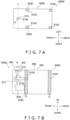
- a frame 500C of a bagmaking and packaging apparatus 1000C shown in FIG. 7A and FIG. 7B as a third conventional example shall have four support posts 510C.
- the support posts 510, 510A, 510B, 510C shall be posts provided upright from the bases (bottom portions) 550 to tops (uppermost portions) 560 of the frames 500, 500A, 500B, 500C.
- the bagmaking and packaging apparatus 1000A to 1000C shall have the same configurations as those of the bagmaking and packaging apparatus 100 except for the frames 500A to 500C.
- the main characteristic of the frame 500 of the bagmaking and packaging apparatus 100 of the present embodiment is the arrangement of the first support post 522 of the first support post group 520 and the second support post 532 of the second support post group 530, and the number of the supports 510 is arbitrary as long as the support posts 510 can support the various devices and parts of the bagmaking and packaging apparatus 100.
- the support posts 510 of the bagmaking and packaging apparatus 100 may include support posts 510 provided upright from positions higher than the base 550 of the frame 500 and/or support posts 510 provided upright as far as positions lower than the top 560 of the frame 500.
- the plural support posts 510 include three support posts 510 of the first support post group 520 disposed on the left side and two support posts 510 of the second support post group 530 disposed on the right side.
- the plural support posts 510 are arranged asymmetrically relative to the virtual line K extending through the left and right direction center of the bagmaking and packaging apparatus 100.
- One advantage of the structure of the frame 500 of the bagmaking and packaging apparatus 100 of the present embodiment is that it is easy to ensure, on the side where the second support post group 530 is disposed (here, the right side) in the left and right direction, work space for the former mechanism 210 and the like.
- the worker opens the door 582 of the cover 580, it is easy for the worker to enter from the right side or the right front side of the bagmaking and packaging apparatus 100, grip hold of the grip unit 218 of the former mechanism 210, and detach the former mechanism 210 from the bagmaking and packaging apparatus 100, because on the right side of the bagmaking and packaging apparatus 100 there is no support post 510 at least in front of the center O of the tube 214.
- detachment of the former mechanism 210 is less likely to be obstructed by a support post 510.
- Another advantage of this structure is the stability of the structure of the frame 500. Specifically, because the first support post 522 is disposed forward of the center O of the tube 214 on the side in the left and right direction where the first support post group 520 is disposed (here, the left side), a heavy object like the metal inspection device 400 (particularly in the present embodiment, part of the heavy object is disposed forward of the center O of the tube 214 as in FIG. 4B ) disposed above the former mechanism 210 and the cover 580 disposed around the former mechanism 210 can be solidly supported.
- the frame 500 of the bagmaking and packaging apparatus 100 of the present embodiment will now be compared with the frames 500A, 500B, 500C of the conventional bagmaking and packaging apparatus 1000A, 1000B, 1000C.
- left and right foremost support posts 522A, 532A are both disposed in positions in which their front ends coincide with the center O of the tube 214 (on the virtual line L extending in the left and right direction and passing through the center O). With this configuration, work space is ensured to a certain extent. However, because both the left and right foremost support posts 522A, 532A are not disposed forward of the center O of the tube 214, it is difficult to stably support a heavy object like the metal inspection device 400 above the former mechanism 210.
- both the left and right foremost support posts 522A, 532A are not disposed forward of the center O of the tube 214, it becomes difficult to solidly support the cover 580 disposed around the former mechanism 210. Furthermore, because both the left and right foremost support posts 522A, 532A are disposed in positions in which their front ends coincide with the center O of the tube 214, maintainability is not sufficiently high compared with a case where the second support post 532 is disposed rearward of the center O of the tube 214 as in the bagmaking and packaging apparatus 100 of the present embodiment.
- the foremost support posts 522B, 532B on the left and right are both disposed forward of the tube 214.
- the metal inspection device 400 that is a heavy object above the former mechanism 210 and the cover 580 disposed around the former mechanism 210 can be stably supported.
- maintainability is poor as described under the heading "Technical Problem" above.
- foremost support posts 522C, 532C on the left and right are both disposed rearward of the tube 214.
- the former mechanism 210 and the metal inspection device 400 become a cantilever structure, and it is difficult for the former mechanism 210 and the metal inspection device 400 to be stably supported.
- the cover 580 disposed around the former mechanism 210 it also becomes difficult for the cover 580 disposed around the former mechanism 210 to be solidly supported.
- the bagmaking and packaging apparatus 100 performs bagmaking and packaging.
- the former mechanism 210 which includes the former 212 and the tube 214 and is disposed forward of the film supply unit 300 disposed in the rear portion of the bagmaking and packaging apparatus 100, forms in a tubular shape the sheet-like film F supplied from the film supply unit 300, and the transverse sealing mechanism 240 transversely seals the tubular film (the tubular film Ft) into which the product C supplied from above is fed.
- the bagmaking and packaging apparatus 100 includes the plural upright support posts 510.
- the plural support posts 510 configure the frame 500 that surrounds at least part of each of the film supply unit 300, the former mechanism 210, and the transverse sealing mechanism 240.
- the plural support posts 510 include the first support post group 520 and the second support post group 530.
- the first support post group 520 and the second support post group 530 each includes a plurality of the support posts 510.
- the support posts 510 of the first support post group 520 are disposed on one lateral side of the bagmaking and packaging apparatus 100 in the left and right direction, and the support posts 510 of the second support post group 530 are disposed on the other lateral side of the bagmaking and packaging apparatus 100 in the left and right direction.
- the first support post 522 disposed foremost among the support posts 510 of the first support post group 520 extends from a lower position to a position higher than the transverse sealing mechanism 240 and, when viewed from above, is disposed forward of the center O of the tube 214.
- the second support post 532 disposed foremost among the support posts 510 of the second support post group 530 extends from a lower position to a position higher than the transverse sealing mechanism 240 and, when viewed from above, is disposed rearward of the center O of the tube 214.
- the second support post 532 is disposed in the above-described position, maintenance space can be ensured on the side of the bagmaking and packaging apparatus 100 in the left and right direction where the second support post group 530 is disposed while inhibiting an increase in the size of the bagmaking and packaging apparatus 100.
- the first support post 522 is disposed in the above-described position.
- various devices and parts of the bagmaking and packaging apparatus 100 can be solidly supported.
- the first support post 522 is disposed forward of the tube 214.
- the heavy object can be solidly supported and vibration of the bagmaking and packaging apparatus 100 can be inhibited.
- the second support post 532 is disposed rearward of the tube 214.
- the first support post 522 supports a member disposed above the former mechanism 210. Specifically, in the present embodiment, the first support post 522 supports the metal inspection device 400 disposed directly above the former mechanism 210.
- the bagmaking and packaging apparatus 100 has the first support post 522 disposed in the above-described position, even if a heavy object such as the metal inspection device 400 is disposed directly above the former mechanism 210, the heavy object can be solidly supported by the frame 500 without upsetting the balance in the support.
- the bagmaking and packaging apparatus 100 includes the cover 580 that covers at least the front side of the former mechanism 210.
- the cover 580 of this bagmaking and packaging apparatus 100 covers the front side, the left side, and the right side of the former mechanism 210.
- the first support post 522 supports the cover 580.
- the cover 580 that covers the former mechanism 210 is installed from the standpoint of safety and hygiene.
- the cover 580 can be solidly supported by the first support post 522 disposed in the above-described position.
- the bagmaking and packaging apparatus 100 may have a former mechanism 210A illustrated in FIG. 8 instead of the former mechanism 210.
- FIG. 8 is a front view for describing the former mechanism 210A of the bagmaking and packaging apparatus 100 pertaining to example modification A, with illustration of the former 212, the plate 216, and the grip unit 218 being omitted.
- the former mechanism 210A has, in addition to the configurations of the former mechanism 210 of the above embodiment, a shutter 215 that moves in the left and right direction and a chute 211 that moves in the up and down direction.
- the shutter 215 and the chute 211 are disposed above the former 212 and the tube 214.
- the chute 211 is a funnel-shaped member that moves up and down between an upper position shown in FIG. 8(a) and a lower position shown in FIG. 8(b) .
- the chute 211 is disposed directly under the combination weigher, and the opening in the upper portion thereof receives the supply of the product C falling from above.
- the chute 211 is mainly disposed in the upper position at the timing when the product C is supplied from the combination weigher.
- the shutter 215 is disposed under the chute 211 disposed in the upper position, and particularly in the vicinity of the lower end of the chute 211.
- the shutter 215 is mainly in a state in which it is closed as in FIG. 8(a) and closes off the opening in the lower end of the chute 211.
- the product C is supplied in this state, the product C is accumulated inside the chute 211.
- the shutter 215 opens and, at the same time, the chute 211 quickly descends inside the tube 214 from the upper position (see the dashed lines in FIG. 8(b) ) to the lower position (see the solid lines in FIG. 8(b) ), and when the chute 211 reaches the lower position, it immediately changes direction and quickly ascends to the upper position.
- the product C can be supplied in an aggregated state to the tubular film Ft in a short amount of time.
- the bagmaking and packaging apparatus 100 has the first support post 522 disposed in the above-described position, the stability of the frame 500 is high, and even if movable members that cause vibration are present, vibration of the bagmaking and packaging apparatus 100 can be reliably inhibited.
- Patent Document 1 JP-A No. 2002-337817
Landscapes
- Engineering & Computer Science (AREA)
- Mechanical Engineering (AREA)
- Containers And Plastic Fillers For Packaging (AREA)
Abstract
Description
- The present invention relates to a bagmaking and packaging apparatus.
- Bagmaking and packaging apparatus such as disclosed in patent document 1 (
JP-A No. 2002-337817 - In such bagmaking and packaging apparatus, maintenance work such as replacing, in accordance with the sizes of the bags for example, a former mechanism that forms the film in the tubular shape and cleaning the area around the former mechanism occurs.
- In the bagmaking and packaging apparatus disclosed in patent document 1 (
JP-A No. 2002-337817 - As a measure to counter reduced maintainability in the bagmaking and packaging apparatus disclosed in patent document 1 (
JP-A No. 2002-337817 - A bagmaking and packaging apparatus pertaining to a first aspect of the invention performs bagmaking and packaging. The bagmaking and packaging apparatus comprises a film supply unit, a former mechanism, a transverse sealing mechanism, plural support posts. The film supply unit is disposed in a rear portion of the bagmaking and packaging apparatus. The film supply unit is configured to supply sheet-like film. The former mechanism includes a former and a tube. The former mechanism is disposed forward of a film supply unit. The former mechanism is configured to form in a tubular shape the sheet-like film supplied from the film supply unit. The transverse sealing mechanism is configured to transversely seal the tubular film in which a product is supplied from above. The plural support posts configure a frame that surrounds at least part of each of the film supply unit, the former mechanism, and the transverse sealing mechanism. The plural support posts include a first support post group and a second support post group. The first support post group and the second support post group each includes a plurality of the support posts. The support posts of the first support post group are disposed on one lateral side of the bagmaking and packaging apparatus in a left and right direction, and the support posts of the second support post group are disposed on the other lateral side of the bagmaking and packaging apparatus in the left and right direction. A first support post disposed foremost among the support posts of the first support post group extends from a low position to a position higher than the transverse sealing mechanism and, when viewed from above, is disposed forward of a center of the tube. A second support post disposed foremost among the support posts of the second support post group extends from a low position to a position higher than the transverse sealing mechanism and, when viewed from above, is disposed rearward of the center of the tube.
- In the bagmaking and packaging apparatus of the first aspect, because the second support post is disposed in the above-described position, maintenance space can be ensured on the side of the bagmaking and packaging apparatus in the left and right direction where the second support post group is disposed while inhibiting an increase in the size of the bagmaking and packaging apparatus.
- Furthermore, in the bagmaking and packaging apparatus of the first aspect, on the side of the bagmaking and packaging apparatus in the left and right direction where the first support post group is disposed, the first support post is disposed in the above-described position. Thus, various devices and parts of the bagmaking and packaging apparatus can be solidly supported.
- A bagmaking and packaging apparatus pertaining to a second aspect of the invention is the bagmaking and packaging apparatus of the first aspect, wherein the first support post is disposed forward of the tube.
- In the bagmaking and packaging apparatus of the second aspect, even when a heavy object is disposed forward of the second support post in the upper portion of the bagmaking and packaging apparatus or when the bagmaking and packaging apparatus is provided with a part that causes the bagmaking and packaging apparatus to vibrate, the heavy object can be solidly supported and vibration of the bagmaking and packaging apparatus can be inhibited.
- A bagmaking and packaging apparatus pertaining to a third aspect of the invention is the bagmaking and packaging apparatus of the first aspect or the second aspect, wherein the second support post is disposed rearward of the tube.
- In the bagmaking and packaging apparatus of the third aspect, it is easy to ensure sufficient work space around the former mechanism. For example, when replacing the former mechanism, movement of the former mechanism is less likely to be obstructed by the second support post.
- A bagmaking and packaging apparatus pertaining to a fourth aspect of the invention is the bagmaking and packaging apparatus of any of the first aspect to the third aspect, wherein the first support post supports a member disposed above the former mechanism.
- Sometimes a heavy object such as a metal detector that detects metal contaminants in the supplied product is disposed above the former mechanism. If such a heavy object is disposed in the upper portion of the bagmaking and packaging apparatus and both the first support post and the second support post are disposed rearward of the center of the tube, there is the risk that the balance in the support will be upset, resulting in a deterioration in the installation stability of the bagmaking and packaging apparatus.
- In contrast, because the bagmaking and packaging apparatus of the fourth aspect has the first support post disposed in the above-described position, even if such a heavy object is present, the heavy object can be solidly supported by the frame.
- A bagmaking and packaging apparatus pertaining to a fifth aspect of the invention is the bagmaking and packaging apparatus of any of the first aspect to the fourth aspect, further including a cover that covers at least a front side of the former mechanism. The first support post supports the cover.
- Sometimes a cover that covers the former mechanism is installed from the standpoint of safety and hygiene. In the bagmaking and packaging apparatus of the fifth aspect, such a cover can be solidly supported by the first support post disposed in the above-described position.
- A bagmaking and packaging apparatus pertaining to a sixth aspect of the invention is the bagmaking and packaging apparatus of any of the first aspect to the fifth aspect, wherein the first support post supports a movable member.
- When the bagmaking and packaging apparatus is provided with a movable member (a member driven to move by a drive unit), vibration may occur as a result of the movable member moving.
- However, because the bagmaking and packaging apparatus of the sixth aspect has the first support post disposed in the above-described position and the stability of the frame is high, even if a movable member that causes vibration is present, vibration of the bagmaking and packaging apparatus can be reliably inhibited.
- In the bagmaking and packaging apparatus of the present invention, a balance between stable support of various devices and parts of the bagmaking and packaging apparatus and high maintainability can be achieved while inhibiting an increase in the apparatus size.
-
-
FIG. 1 is a schematic perspective view of a packaging and inspection system including a bagmaking and packaging apparatus of an embodiment of the invention; -
FIG. 2 is a schematic perspective view of the bagmaking and packaging apparatus ofFIG. 1 ; -
FIG. 3 is a diagram showing the schematic configuration of the bagmaking and packaging apparatus ofFIG. 1 ; -
FIG. 4A is a schematic plan view illustrating the arrangement of support posts of a frame of the bagmaking and packaging apparatus ofFIG. 1 ; -
FIG. 4B is a schematic right side view illustrating the arrangement of the support posts of the frame of the bagmaking and packaging apparatus ofFIG. 4A ; -
FIG. 5A is a schematic plan view illustrating the arrangement of support posts of a bagmaking and packaging apparatus of a first conventional example; -
FIG. 5B is a schematic right side view illustrating the arrangement of the support posts of the bagmaking and packaging apparatus ofFIG. 5A ; -
FIG. 6A is a schematic plan view illustrating the arrangement of support posts of a bagmaking and packaging apparatus of a second conventional example; -
FIG. 6B is a schematic right side view illustrating the arrangement of the support posts of the bagmaking and packaging apparatus ofFIG. 6A ; -
FIG. 7A is a schematic plan view illustrating the arrangement of support posts of a bagmaking and packaging apparatus of a third conventional example; -
FIG. 7B is a schematic right side view illustrating the arrangement of the support posts of the bagmaking and packaging apparatus ofFIG. 7A ; and -
FIG. 8 is a front view for describing a former mechanism of the bagmaking and packaging apparatus pertaining to example modification A, with illustration of a former, a plate, and a grip unit being omitted. - A bagmaking and
packaging apparatus 100 that is an embodiment of the bagmaking and packaging apparatus of the present invention will be described with reference to the drawings. It will be noted that the following embodiment is merely a specific example of the invention and is not intended to limit the technical scope of the invention. - In the following description, expressions such as perpendicular, orthogonal, horizontal, and vertical may be sometimes used to describe directions and positional relationships, but these expressions are not limited to their strict senses and include cases where that which they describe are substantially perpendicular, orthogonal, horizontal, or vertical. Furthermore, in the following description, expressions such as front, rear, above, below, left, and right are used to indicate directions and such. Unless otherwise specified, front, rear, above, under, left, and right here follow the directions of the arrows added to the drawings.
- It will be noted that in the present disclosure, the side where a later-described
film supply unit 300 is disposed as viewed from the position of a later-described bagmaking andpackaging unit 200 will be defined as the rear, and the side where the bagmaking andpackaging unit 200 is disposed as viewed from the position of thefilm supply unit 300 will be defined as the front. Furthermore, a direction that is a horizontal direction and orthogonal to the front and rear direction in which the bagmaking andpackaging unit 200 and thefilm supply unit 300 are lined up will be defined as the left and right direction. - A packaging and inspection system 1 including the bagmaking and
packaging apparatus 100 pertaining to the embodiment of the invention will now be described with reference toFIG. 1 to FIG. 3 .FIG. 1 is a schematic perspective view of the packaging and inspection system 1 including the bagmaking andpackaging apparatus 100.FIG. 2 is a schematic perspective view of the bagmaking andpackaging apparatus 100.FIG. 3 is a diagram showing the schematic configuration of the bagmaking andpackaging apparatus 100. - It will be noted that
FIG. 2 illustrates a state in which a later-describeddoor 582 disposed in the front upper portion of the bagmaking andpackaging apparatus 100 is open and a protective plate 590 (seeFIG. 1 ) disposed in the front lower portion of the bagmaking andpackaging apparatus 100 is detached. Furthermore,FIG. 2 illustrates a state in which, for the purpose of maintenance or the like, a later-describedformer mechanism 210 andlongitudinal sealing mechanism 230 have been moved from the positions they are in when the bagmaking andpackaging apparatus 100 is operating. - As shown in
FIG. 1 , the packaging and inspection system 1 mainly includes the bagmaking andpackaging apparatus 100, aconveyance apparatus 2, and aseal checker 3. - The bagmaking and
packaging apparatus 100 makes a bag-like packaging material from a sheet-like film F to thereby make bags B containing a product C inside (seeFIG. 3 ). The product C to be contained in the bags B is supplied to the bagmaking andpackaging apparatus 100 from a combination weigher (not shown in the drawings) disposed above the bagmaking andpackaging apparatus 100. The bags B made by the bagmaking andpackaging apparatus 100 are conveyed by theconveyance apparatus 2. Theseal checker 3 checks the seals of the bags B (whether or not the bags B are airtight) conveyed by theconveyance apparatus 2. - Here, the combination weigher uses multiple weigh hoppers to measure weights of the product C, combines weigh values obtained by the multiple weigh hoppers so that the total weight thereof is in a predetermined weight range, and drops the product C for which the total combined weight is within the predetermined weight range to thereby supply it to the bagmaking and
packaging apparatus 100. - The
conveyance apparatus 2 is a conveyor extending forward from below atransverse sealing mechanism 240 of the bagmaking andpackaging apparatus 100. Theconveyance apparatus 2 conveys forward the bags B made by the bagmaking andpackaging apparatus 100 and transfers them to a process downstream of the packaging and inspection system 1 (e.g., a conveyor that conveys the bags B to a box packing apparatus). - As shown in
FIG. 1 to FIG. 3 , the bagmaking andpackaging apparatus 100 mainly includes afilm supply unit 300, a bagmaking andpackaging unit 200, ametal inspection device 400, aframe 500, and a control device (such as computer, control board and PLC not shown in the drawings). Thefilm supply unit 300 is disposed in the rear portion of the bagmaking andpackaging apparatus 100. Thefilm supply unit 300 supplies the sheet-like film F to the bagmaking andpackaging unit 200 disposed forward of thefilm supply unit 300. The bagmaking andpackaging unit 200 is disposed in the front portion of the bagmaking andpackaging apparatus 100. The bagmaking andpackaging unit 200 forms the sheet-like film F in a tubular shape and transversely seals the film F formed in the tubular shape (a tubular film Ft) to make the bags B. Themetal inspection device 400 inspects for contaminants (metal) in the product C dropped and supplied from the combination weigher (not shown in the drawings) to the bagmaking andpackaging apparatus 100. Theframe 500 mainly supports thefilm supply unit 300, the bagmaking andpackaging unit 200, and themetal inspection device 400. The control device controls the operation of each part of thefilm supply unit 300 and the bagmaking andpackaging unit 200 and performs various calculations and processes. - The bagmaking and
packaging apparatus 100 will now be described in detail. - The
film supply unit 300 is disposed in the rear portion of the bagmaking andpackaging apparatus 100. Thefilm supply unit 300 is disposed rearward of the bagmaking andpackaging unit 200 and next to the bagmaking andpackaging unit 200. Thefilm supply unit 300 supplies the sheet-like film F to a later-describedformer mechanism 210 of the bagmaking andpackaging unit 200 disposed forward of thefilm supply unit 300. - As shown in
FIG. 3 , thefilm supply unit 300 mainly includes a filmroll support mechanism 310 and aguide mechanism 320. - The film
roll support mechanism 310 holds a film roll FR in which the sheet-like film F is wound about a core (not shown in the drawings). The filmroll support mechanism 310 uses a drive unit such as a motor (not shown in the drawings) to rotate ashaft 312 to which the core of the film roll FR is attached (seeFIG. 1 to FIG. 3 ) and pay out the film F from the film roll FR. - The
guide mechanism 320 includes plural rollers disposed along a conveyance path of the film F. Theguide mechanism 320 guides to theformer mechanism 210 of the bagmaking andpackaging unit 200 the film F paid out from the film roll FR. - As shown in
FIG. 3 , the bagmaking andpackaging unit 200 mainly includes aformer mechanism 210, aconveyance mechanism 220, alongitudinal sealing mechanism 230, and atransverse sealing mechanism 240. - The
former mechanism 210 mainly includes a former 212, atube 214, aplate 216, and agrip unit 218. - The former 212 is disposed so as to surround the
tubular tube 214 and forms in a tubular shape the sheet-like film F conveyed thereto from thefilm supply unit 300 disposed in the rear portion of the bagmaking andpackaging apparatus 100 by bending the film F so that left and right end portions of the film F in the width direction overlap each other. The tubular film Ft formed by the former 212 is guided so as to become wrapped around the outer peripheral surface of the lower portion of thetubular tube 214 and is conveyed downward in a state in which it is wrapped around thetube 214. It will be noted that hereinafter the portion of thetube 214 around which the tubular film Ft is wrapped is sometimes called theportion 214a. - The
tube 214 is a tubular member that extends in the vertical direction and has upper and lower end portions that are open. The lower end of thetube 214 is disposed higher than the transverse sealing mechanism 240 (higher than areas where later-describedrotating bodies 242 of thetransverse sealing mechanism 240 rotate) so as not to hinder the movement of therotating bodies 242. Thetube 214 receives the falling product C in the upper opening of thetube 214 and supplies, from the lower opening of thetube 214 to the inside of the tubular film Ft, the product C fed through the upper opening. - The
plate 216 is mounted on and secured to a mount (not shown in the drawings) supported by theframe 500, and is supported by theframe 500 via the mount. The former 212 and thetube 214 are attached to theplate 216 directly or via another member, and theplate 216 supports the former 212 and thetube 214. Thegrip unit 218 is attached to theplate 216 directly or via another member. When attaching theformer mechanism 210 to the mount or detaching theformer mechanism 210 from the mount, a worker grips hold of thegrip unit 218 and moves theformer mechanism 210. - The
conveyance mechanism 220 is disposed under theplate 216 of theformer mechanism 210. Theconveyance mechanism 220 is disposed on the left and right sides of theportion 214a of thetube 214 around which the tubular film Ft is wrapped. Theconveyance mechanism 220 conveys to theformer mechanism 210 the film F paid out from the film roll FR and conveys to thetransverse sealing mechanism 240 the tubular film Ft formed by the former 212. Theconveyance mechanism 220 has pull-downbelts 226 having a suction function, and theconveyance mechanism 220 conveys the tubular film Ft downward as a result ofdrive rollers 222 around which the pull-downbelts 226 are entrained being driven by a drive mechanism such as a motor (not shown in the drawings) in a state in which the pull-downbelts 226 are sucking hold the film F. - The
longitudinal sealing mechanism 230 seals the overlapping portion of the tubular film Ft at which the left and right end portions of the tubular film Ft overlap each other. Thelongitudinal sealing mechanism 230 is disposed in front of a path on which is conveyed the overlapping portion of the tubular film Ft, which is conveyed in a state in which the tubular film Ft is wrapped around thetube 214. Thelongitudinal sealing mechanism 230 has a built-in heater (not shown in the drawings) inside. When thelongitudinal sealing mechanism 230 with its heater turned on is driven by a drive unit (not shown in the drawings) so that thelongitudinal sealing mechanism 230 is pressed against thetube 214 via the tubular film Ft, the overlapping portion of the tubular film Ft is sealed in the up and down direction (the longitudinal direction). - As shown in
FIG. 3 , thetransverse sealing mechanism 240 is disposed below thelongitudinal sealing mechanism 230. Thetransverse sealing mechanism 240 transversely seals the top and bottom of a segment of the tubular film Ft corresponding to one bag B (used to make one bag B) to make a bag B containing the product C. Specifically, thetransverse sealing mechanism 240 transversely seals, in a direction orthogonal to a conveyance direction A of the tubular film Ft, the longitudinally sealed tubular film Ft conveyed downward by theconveyance mechanism 220 to thereby form transverse seal portions of the bag B. - As shown in
FIG. 3 , thetransverse sealing mechanism 240 mainly includes a pair ofrotating bodies 242 disposed in front of and in back of the tubular film Ft. Eachrotating body 242 includes anarm 243 that is configured to be rotatable about an axis of rotation X and sealingjaws arm 243 and have built-in heaters. The sealingjaws 244a of both rotatingbodies 242 function as a pair to transversely seal the tubular film Ft. The sealingjaws 244b of both rotatingbodies 242 also function as a pair to transversely seal the tubular film Ft. The pair of sealingjaws 244a and the pair of sealingjaws 244b alternatingly transversely seal the tubular film Ft conveyed thereto. One of the pair of sealingjaws 244a and one of the pair of sealingjaws 244b are each provided with a cutter (not illustrated), and thetransverse sealing mechanism 240 cuts the transversely sealed portion in a direction orthogonal to the conveyance direction A of the tubular film Ft to thereby cut the bag B away from the trailing tubular film Ft at the timing when the pair of sealingjaws 244a perform heat sealing or at the timing when the pair of sealingjaws 244b perform heat sealing. - The
metal inspection device 400 is disposed above the upper end of thetube 214 of theformer mechanism 210. In other words, themetal inspection device 400 is disposed above theformer mechanism 210. In particular, here, themetal inspection device 400 is disposed directly above theformer mechanism 210. At least part of themetal inspection device 400 is disposed forward of a center O of thetube 214. A definition for the center O of thetube 214 will be given later. Themetal inspection device 400 inspects for contaminants (metal) in the product C dropped and supplied from the combination weigher to the opening in the upper end of thetube 214. Themetal inspection device 400 is supported by theframe 500. - The
metal inspection device 400 itself is a known device, so detailed description thereof will be omitted. - The
frame 500 will now be described with reference toFIG. 4A and FIG. 4B. FIG. 4A is a schematic plan view illustrating the arrangement ofsupport posts 510 of theframe 500 of the bagmaking andpackaging apparatus 100.FIG. 4B is a schematic right side view illustrating the arrangement of the support posts 510 of theframe 500 of the bagmaking andpackaging apparatus 100. It will be noted that inFIG. 4A and FIG. 4B hatching is added to the support posts 510 from the standpoint of facilitating understanding of the drawings. - The
frame 500 supports various devices and parts of thefilm supply unit 300, various devices and parts of the bagmaking andpackaging unit 200, and themetal inspection device 400 of the bagmaking andpackaging apparatus 100. - The
frame 500 includes, for example, plural upright support posts 510 and beams that bridge the support posts 510. In other words, theframe 500 is configured by, for example, the support posts 510 and the beams. Here, particularly the support posts 510, which are the characteristic configuration of the bagmaking andpackaging apparatus 100, will be mainly described. - The
frame 500 having the plural support posts 510 surrounds at least part of each of thefilm supply unit 300, theformer mechanism 210, and thetransverse sealing mechanism 240. - Here, the recitation that the
frame 500 surrounds at least part of thefilm supply unit 300 means that, when viewed from above, at least part of thefilm supply unit 300 is disposed in an area (in the rectangle inFIG. 4A ) defined by a virtual line extending in the left and right direction and passing through thesupport post 510 disposed foremost, a virtual line extending in the left and right direction and passing through the support posts 510 disposed rearmost, a virtual line extending in the front and rear direction and passing through the support posts 510 disposed rightmost, and a virtual line extending in the front and rear direction and passing through the support posts 510 disposed leftmost. The meanings of the recitation that theframe 500 surrounds at least part of theformer mechanism 210 and the recitation that theframe 500 surrounds at least part of thetransverse sealing mechanism 240 are similarly defined. - The plural support posts 510 include a first
support post group 220 including a plurality of the support posts 510 disposed on one lateral side of the bagmaking andpackaging apparatus 100 in the left and right direction (relative to a virtual line K extending in the front and rear direction through the left and right direction center of the bagmaking and packaging apparatus 100) and a secondsupport post group 530 including a plurality of the support posts 510 disposed on the other lateral side in the left and right direction (seeFIG. 4A ). In the present embodiment, the support posts 510 included in the firstsupport post group 520 are disposed on the left side in the bagmaking andpackaging apparatus 100. The support posts 510 included in the secondsupport post group 530 are disposed on the right side in the bagmaking andpackaging apparatus 100. It will be noted that this arrangement of the firstsupport post group 520 and the secondsupport post group 530 is merely an example, and the firstsupport post group 520 having later-described characteristics may be disposed on the right side in the bagmaking andpackaging apparatus 100 and the secondsupport post group 520 having later-described characteristics may be disposed on the left side in the bagmaking andpackaging apparatus 100. - In the bagmaking and
packaging apparatus 100, the plural support posts 510 are arranged asymmetrically relative to the virtual line K extending through the left and right direction center of the bagmaking andpackaging apparatus 100. - Specifically, a
first support post 522 disposed foremost among the support posts 510 of the firstsupport post group 520 is disposed forward of the center O of the tube 214 (forward of a virtual line L passing through the center O) when viewed from above. More preferably, thefirst support post 522 is disposed forward of the tube 214 (in particular, here, theportion 214a of thetube 214 around which the tubular film Ft formed in the tubular shape by the former 212 is wrapped). In contrast, asecond support post 532 disposed foremost among the support posts 510 of the secondsupport post group 530 is disposed rearward of the center O of the tube 214 (rearward of the virtual line L passing through the center O) when viewed from above. More preferably, thesecond support post 532 is disposed rearward of the tube 214 (in particular, here,portion 214a of the tube 214). - It will be noted that, here, the center O of the
tube 214 means the position of the center of gravity of a cross-section obtained by horizontally cutting theportion 214a of thetube 214. For example, if the cross-sectional shape of theportion 214a of thetube 214 is circular, the center O of thetube 214 is the center of the cross-section obtained by horizontally cutting theportion 214a of thetube 214. It will be noted that the cross-sectional shape of theportion 214a of thetube 214 may also be a shape other than circular, and the outer shape of theportion 214a of thetube 214 may also be oval, for example. - The
first support post 522 extends from a position lower than thetransverse sealing mechanism 240 to a position higher than thetransverse sealing mechanism 240. Thesecond support post 532 also extends from a position lower than thetransverse sealing mechanism 240 to a position higher than thetransverse sealing mechanism 240. For example, specifically, thefirst support post 522 and thesecond support post 532 extend from a base 550 in the bottom portion of the bagmaking andpackaging apparatus 100 to a position higher than the upper end of thetube 214 of theformer mechanism 210. - The
first support post 522 and thesecond support post 532, for example, directly or indirectly support theformer mechanism 210. Particularly, thefirst support post 522 supports themetal inspection device 400 that is a heavy object disposed higher than theformer mechanism 210. Thefirst support post 522 supports acover 580 of the bagmaking andpackaging apparatus 100. - Here, the
cover 580 is a member that covers the front side and the right side of theformer mechanism 210. Thecover 580 is attached to thefirst support post 522, and thefirst support post 522 supports thecover 580. Thecover 580 is adoor 582 that can be opened and closed. During maintenance, for example, a worker can access theformer mechanism 210, theconveyance mechanism 220, and thelongitudinal sealing mechanism 230 by swinging thedoor 582 on hinges provided on the first support post 522 (seeFIG. 2 ). - Below, advantageous effects obtained by arranging the support posts 510 as illustrated in
FIG. 4A and FIG. 4B will be described with reference also toFIG. 5A to FIG. 7B . - It will be noted that, here, the
frame 500 of the bagmaking andpackaging apparatus 100 of the present embodiment shall have five support posts 510. Aframe 500A of a bagmaking andpackaging apparatus 1000A shown inFIG. 5A and FIG. 5B as a first conventional example and aframe 500B of a bagmaking andpackaging apparatus 1000B shown inFIG. 6A and FIG. 6B as a second conventional example shall each have sixsupport posts frame 500C of a bagmaking andpackaging apparatus 1000C shown inFIG. 7A and FIG. 7B as a third conventional example shall have foursupport posts 510C. - Here, the support posts 510, 510A, 510B, 510C shall be posts provided upright from the bases (bottom portions) 550 to tops (uppermost portions) 560 of the
frames packaging apparatus 1000A to 1000C shall have the same configurations as those of the bagmaking andpackaging apparatus 100 except for theframes 500A to 500C. - However, the main characteristic of the
frame 500 of the bagmaking andpackaging apparatus 100 of the present embodiment is the arrangement of thefirst support post 522 of the firstsupport post group 520 and thesecond support post 532 of the secondsupport post group 530, and the number of thesupports 510 is arbitrary as long as the support posts 510 can support the various devices and parts of the bagmaking andpackaging apparatus 100. Furthermore, the support posts 510 of the bagmaking andpackaging apparatus 100 may include support posts 510 provided upright from positions higher than thebase 550 of theframe 500 and/orsupport posts 510 provided upright as far as positions lower than the top 560 of theframe 500. - In the example of
FIG. 4A , the plural support posts 510 include threesupport posts 510 of the firstsupport post group 520 disposed on the left side and twosupport posts 510 of the secondsupport post group 530 disposed on the right side. In the example ofFIG. 4A , as mentioned above, the plural support posts 510 are arranged asymmetrically relative to the virtual line K extending through the left and right direction center of the bagmaking andpackaging apparatus 100. - One advantage of the structure of the
frame 500 of the bagmaking andpackaging apparatus 100 of the present embodiment is that it is easy to ensure, on the side where the secondsupport post group 530 is disposed (here, the right side) in the left and right direction, work space for theformer mechanism 210 and the like. Specifically, as shown inFIG. 2 , when a worker opens thedoor 582 of thecover 580, it is easy for the worker to enter from the right side or the right front side of the bagmaking andpackaging apparatus 100, grip hold of thegrip unit 218 of theformer mechanism 210, and detach theformer mechanism 210 from the bagmaking andpackaging apparatus 100, because on the right side of the bagmaking andpackaging apparatus 100 there is nosupport post 510 at least in front of the center O of thetube 214. Furthermore, because on the right side of the bagmaking andpackaging apparatus 100 there is nosupport post 510 at least forward of the center O of thetube 214, detachment of theformer mechanism 210 is less likely to be obstructed by asupport post 510. - Another advantage of this structure is the stability of the structure of the
frame 500. Specifically, because thefirst support post 522 is disposed forward of the center O of thetube 214 on the side in the left and right direction where the firstsupport post group 520 is disposed (here, the left side), a heavy object like the metal inspection device 400 (particularly in the present embodiment, part of the heavy object is disposed forward of the center O of thetube 214 as inFIG. 4B ) disposed above theformer mechanism 210 and thecover 580 disposed around theformer mechanism 210 can be solidly supported. - The
frame 500 of the bagmaking andpackaging apparatus 100 of the present embodiment will now be compared with theframes packaging apparatus - In the
frame 500A of the bagmaking andpackaging apparatus 1000A, as shown inFIG. 5A and FIG. 5B , left and right foremost support posts 522A, 532A are both disposed in positions in which their front ends coincide with the center O of the tube 214 (on the virtual line L extending in the left and right direction and passing through the center O). With this configuration, work space is ensured to a certain extent. However, because both the left and right foremost support posts 522A, 532A are not disposed forward of the center O of thetube 214, it is difficult to stably support a heavy object like themetal inspection device 400 above theformer mechanism 210. Furthermore, because both the left and right foremost support posts 522A, 532A are not disposed forward of the center O of thetube 214, it becomes difficult to solidly support thecover 580 disposed around theformer mechanism 210. Furthermore, because both the left and right foremost support posts 522A, 532A are disposed in positions in which their front ends coincide with the center O of thetube 214, maintainability is not sufficiently high compared with a case where thesecond support post 532 is disposed rearward of the center O of thetube 214 as in the bagmaking andpackaging apparatus 100 of the present embodiment. - Next, in the
frame 500B of the bagmaking andpackaging apparatus 1000B, the foremost support posts 522B, 532B on the left and right are both disposed forward of thetube 214. With this arrangement of the support posts 522B, 532B, themetal inspection device 400 that is a heavy object above theformer mechanism 210 and thecover 580 disposed around theformer mechanism 210 can be stably supported. However, owing to the presence of the support posts 522B, 532B, maintainability is poor as described under the heading "Technical Problem" above. It will be noted that if the foremost support posts 522B, 532B were disposed further away from the support posts 510B, 510B in the second row from the front, maintainability might be able to be ensured, but this causes another problem, which is that the installation space of the bagmaking andpackaging apparatus 1000B increases. - Next, in the
frame 500C of the bagmaking andpackaging apparatus 1000C, foremost support posts 522C, 532C on the left and right are both disposed rearward of thetube 214. With this configuration, work space is easily ensured and the maintainability of the bagmaking andpackaging apparatus 1000C is high. However, because both the left and right foremost support posts 522C, 532C are not disposed forward of thetube 214, theformer mechanism 210 and themetal inspection device 400 become a cantilever structure, and it is difficult for theformer mechanism 210 and themetal inspection device 400 to be stably supported. Moreover, it also becomes difficult for thecover 580 disposed around theformer mechanism 210 to be solidly supported. - As is apparent from the above comparisons, with the bagmaking and
packaging apparatus 100 of the present embodiment, a balance between stable support of various devices and parts and high maintainability, which could not be obtained with the configurations of the conventional bagmaking and packaging apparatus, can be achieved without increasing the apparatus size. - (3-1) The bagmaking and
packaging apparatus 100 performs bagmaking and packaging. In the bagmaking and packaging, theformer mechanism 210, which includes the former 212 and thetube 214 and is disposed forward of thefilm supply unit 300 disposed in the rear portion of the bagmaking andpackaging apparatus 100, forms in a tubular shape the sheet-like film F supplied from thefilm supply unit 300, and thetransverse sealing mechanism 240 transversely seals the tubular film (the tubular film Ft) into which the product C supplied from above is fed. The bagmaking andpackaging apparatus 100 includes the plural upright support posts 510. The plural support posts 510 configure theframe 500 that surrounds at least part of each of thefilm supply unit 300, theformer mechanism 210, and thetransverse sealing mechanism 240. The plural support posts 510 include the firstsupport post group 520 and the secondsupport post group 530. The firstsupport post group 520 and the secondsupport post group 530 each includes a plurality of the support posts 510. The support posts 510 of the firstsupport post group 520 are disposed on one lateral side of the bagmaking andpackaging apparatus 100 in the left and right direction, and the support posts 510 of the secondsupport post group 530 are disposed on the other lateral side of the bagmaking andpackaging apparatus 100 in the left and right direction. Thefirst support post 522 disposed foremost among the support posts 510 of the firstsupport post group 520 extends from a lower position to a position higher than thetransverse sealing mechanism 240 and, when viewed from above, is disposed forward of the center O of thetube 214. Thesecond support post 532 disposed foremost among the support posts 510 of the secondsupport post group 530 extends from a lower position to a position higher than thetransverse sealing mechanism 240 and, when viewed from above, is disposed rearward of the center O of thetube 214. - In the bagmaking and
packaging apparatus 100, because thesecond support post 532 is disposed in the above-described position, maintenance space can be ensured on the side of the bagmaking andpackaging apparatus 100 in the left and right direction where the secondsupport post group 530 is disposed while inhibiting an increase in the size of the bagmaking andpackaging apparatus 100. - Furthermore, in the bagmaking and
packaging apparatus 100, on the side of the bagmaking andpackaging apparatus 100 in the left and right direction where the firstsupport post group 520 is disposed, thefirst support post 522 is disposed in the above-described position. Thus, various devices and parts of the bagmaking andpackaging apparatus 100 can be solidly supported. - (3-2) In the bagmaking and
packaging apparatus 100, thefirst support post 522 is disposed forward of thetube 214. - In the bagmaking and
packaging apparatus 100, even when a heavy object is disposed forward of thesecond support post 532 in the upper portion of the bagmaking andpackaging apparatus 100 or when the bagmaking andpackaging apparatus 100 is provided with a part that causes the bagmaking andpackaging apparatus 100 to vibrate, the heavy object can be solidly supported and vibration of the bagmaking andpackaging apparatus 100 can be inhibited. - (3-3) In the bagmaking and
packaging apparatus 100, thesecond support post 532 is disposed rearward of thetube 214. - In the bagmaking and
packaging apparatus 100, it is easy to ensure sufficient work space around theformer mechanism 210. For example, when replacing theformer mechanism 210, movement of theformer mechanism 210 is less likely to be obstructed by thesecond support post 532. - (3-4) In the bagmaking and
packaging apparatus 100, thefirst support post 522 supports a member disposed above theformer mechanism 210. Specifically, in the present embodiment, thefirst support post 522 supports themetal inspection device 400 disposed directly above theformer mechanism 210. - Because the bagmaking and
packaging apparatus 100 has thefirst support post 522 disposed in the above-described position, even if a heavy object such as themetal inspection device 400 is disposed directly above theformer mechanism 210, the heavy object can be solidly supported by theframe 500 without upsetting the balance in the support. - (3-5) The bagmaking and
packaging apparatus 100 includes thecover 580 that covers at least the front side of theformer mechanism 210. Thecover 580 of this bagmaking andpackaging apparatus 100 covers the front side, the left side, and the right side of theformer mechanism 210. Thefirst support post 522 supports thecover 580. - In this bagmaking and
packaging apparatus 100, thecover 580 that covers theformer mechanism 210 is installed from the standpoint of safety and hygiene. In the bagmaking andpackaging apparatus 100, thecover 580 can be solidly supported by thefirst support post 522 disposed in the above-described position. - Examples modifications of the above embodiment will be described below. It will be noted that some or all of the content of each example modification may be combined with the content of the above embodiment and/or the content of another example modification to the extent that they are not mutually contradictory.
- The bagmaking and
packaging apparatus 100 may have aformer mechanism 210A illustrated inFIG. 8 instead of theformer mechanism 210.FIG. 8 is a front view for describing theformer mechanism 210A of the bagmaking andpackaging apparatus 100 pertaining to example modification A, with illustration of the former 212, theplate 216, and thegrip unit 218 being omitted. - The
former mechanism 210A has, in addition to the configurations of theformer mechanism 210 of the above embodiment, ashutter 215 that moves in the left and right direction and achute 211 that moves in the up and down direction. Theshutter 215 and thechute 211 are disposed above the former 212 and thetube 214. - The
chute 211 is a funnel-shaped member that moves up and down between an upper position shown inFIG. 8(a) and a lower position shown inFIG. 8(b) . Thechute 211 is disposed directly under the combination weigher, and the opening in the upper portion thereof receives the supply of the product C falling from above. - The
chute 211 is mainly disposed in the upper position at the timing when the product C is supplied from the combination weigher. Theshutter 215 is disposed under thechute 211 disposed in the upper position, and particularly in the vicinity of the lower end of thechute 211. At the timing when the product C is supplied from the combination weigher, theshutter 215 is mainly in a state in which it is closed as inFIG. 8(a) and closes off the opening in the lower end of thechute 211. When the product C is supplied in this state, the product C is accumulated inside thechute 211. - Then, for example, near the end of the timing when the product C is supplied from the combination weigher, or at the timing when the supply of the product C from the combination weigher has ended, the
shutter 215 opens and, at the same time, thechute 211 quickly descends inside thetube 214 from the upper position (see the dashed lines inFIG. 8(b) ) to the lower position (see the solid lines inFIG. 8(b) ), and when thechute 211 reaches the lower position, it immediately changes direction and quickly ascends to the upper position. In this configuration, the product C can be supplied in an aggregated state to the tubular film Ft in a short amount of time. - However, when the bagmaking and
packaging apparatus 100 has such movable members (thechute 211 and the shutter 215), vibration may occur as a result of the movable members moving. - However, because the bagmaking and
packaging apparatus 100 has thefirst support post 522 disposed in the above-described position, the stability of theframe 500 is high, and even if movable members that cause vibration are present, vibration of the bagmaking andpackaging apparatus 100 can be reliably inhibited. -
- 100:
- Bagmaking and Packaging Apparatus
- 210:
- Former Mechanism
- 210A:
- Former Mechanism
- 211:
- Chute (Movable Member)
- 212:
- Former
- 214:
- Tube
- 215:
- Shutter
- 240:
- Transverse Sealing Mechanism
- 300:
- Film Supply Unit
- 400:
- Metal Inspection Device
- 500:
- Frame
- 510:
- Support Posts
- 520:
- First Support Post Group
- 522:
- First Support Post
- 530:
- Second Support Post Group
- 532:
- Second Support Post
- 580:
- Cover
- C:
- Product
- F:
- Film
- Ft:
- Tubular Film
- O:
- Center (Center of Tube)
- Patent Document 1:
JP-A No. 2002-337817
Claims (6)
- A bagmaking and packaging apparatus comprisinga film supply unit disposed in a rear portion of the apparatus and configured to supply sheet-like film;a former mechanism including a former and a tube and being disposed forward of the film supply unit, the former mechanism configured to form in a tubular shape the sheet-like film supplied from the film supply unit,a transverse sealing mechanism configured to transversely seal the tubular film in which a product being supplied from above; andplural upright support posts that configure a frame that surrounds at least part of each of the film supply unit, the former mechanism, and the transverse sealing mechanism,whereinthe plural support posts include:a first support post group including a plurality of the support posts disposed on one lateral side of the bagmaking and packaging apparatus in a left and right direction; anda second support post group including a plurality of the support posts disposed on the other lateral side in the left and right direction,a first support post disposed foremost among the support posts of the first support post group extends from a low position to a position higher than the transverse sealing mechanism and, when viewed from above, is disposed forward of a center of the tube, anda second support post disposed foremost among the support posts of the second support post group extends from a low position to a position higher than the transverse sealing mechanism and, when viewed from above, is disposed rearward of the center of the tube.
- The bagmaking and packaging apparatus of claim 1, wherein the first support post is disposed forward of the tube.
- The bagmaking and packaging apparatus of claim 1 or 2, wherein the second support post is disposed rearward of the tube.
- The bagmaking and packaging apparatus any one of claims 1 to 3, wherein the first support post supports a member disposed above the former mechanism.
- The bagmaking and packaging apparatus any one of claims 1 to 4, further comprising a cover that is configured to cover at least a front side of the former mechanism,
wherein
the first support post supports the cover. - The bagmaking and packaging apparatus any one of claims 1 to 5, wherein the first support post supports a movable member.
Applications Claiming Priority (2)
| Application Number | Priority Date | Filing Date | Title |
|---|---|---|---|
| JP2022196189A JP2024082383A (en) | 2022-12-08 | 2022-12-08 | Bag making and packaging equipment |
| JP2023002167A JP2024098592A (en) | 2023-01-11 | 2023-01-11 | Bag making and packaging equipment |
Publications (2)
| Publication Number | Publication Date |
|---|---|
| EP4382436A1 true EP4382436A1 (en) | 2024-06-12 |
| EP4382436B1 EP4382436B1 (en) | 2025-04-09 |
Family
ID=88975751
Family Applications (1)
| Application Number | Title | Priority Date | Filing Date |
|---|---|---|---|
| EP23214131.7A Active EP4382436B1 (en) | 2022-12-08 | 2023-12-04 | Bagmaking and packaging apparatus |
Country Status (2)
| Country | Link |
|---|---|
| US (1) | US12378020B2 (en) |
| EP (1) | EP4382436B1 (en) |
Citations (2)
| Publication number | Priority date | Publication date | Assignee | Title |
|---|---|---|---|---|
| JP2002337817A (en) | 2001-05-21 | 2002-11-27 | Ishida Co Ltd | Bag making and packaging machine |
| AU2016216967A1 (en) * | 2015-02-12 | 2017-08-03 | Ishida Co., Ltd. | Measuring packaging system |
Family Cites Families (7)
| Publication number | Priority date | Publication date | Assignee | Title |
|---|---|---|---|---|
| US6421987B1 (en) * | 1999-01-08 | 2002-07-23 | Ishida Co., Ltd. | Latitudinal sealing mechanism for bag-packaging machine and a bag packaging machine having the same |
| US6769229B2 (en) * | 2001-08-30 | 2004-08-03 | Kraft Foods Holdings, Inc. | Method for manufacturing flexible packages having slide closures |
| JP2004155432A (en) * | 2002-11-01 | 2004-06-03 | Ishida Co Ltd | Bag making and packaging machine |
| AU2003903509A0 (en) * | 2003-07-08 | 2003-07-24 | Tna Australia Pty Limited | A packaging machine former support |
| JP5000362B2 (en) * | 2007-04-06 | 2012-08-15 | 株式会社イシダ | Bag making and packaging machine |
| JP2012236621A (en) * | 2011-05-11 | 2012-12-06 | Ishida Co Ltd | Form-fill-seal machine |
| EP3514074A4 (en) * | 2016-09-16 | 2019-07-31 | Ishida Co., Ltd. | WEIGHING / PACKING DEVICE |
-
2023
- 2023-11-30 US US18/523,925 patent/US12378020B2/en active Active
- 2023-12-04 EP EP23214131.7A patent/EP4382436B1/en active Active
Patent Citations (2)
| Publication number | Priority date | Publication date | Assignee | Title |
|---|---|---|---|---|
| JP2002337817A (en) | 2001-05-21 | 2002-11-27 | Ishida Co Ltd | Bag making and packaging machine |
| AU2016216967A1 (en) * | 2015-02-12 | 2017-08-03 | Ishida Co., Ltd. | Measuring packaging system |
Also Published As
| Publication number | Publication date |
|---|---|
| EP4382436B1 (en) | 2025-04-09 |
| US20240190598A1 (en) | 2024-06-13 |
| US12378020B2 (en) | 2025-08-05 |
Similar Documents
| Publication | Publication Date | Title |
|---|---|---|
| US7334378B2 (en) | Packaging machine and weighing apparatus | |
| JP2009255988A5 (en) | ||
| US8015783B2 (en) | Form-fill-seal machine | |
| JP2009255988A (en) | Packaging machine | |
| US7228673B2 (en) | Seasoning treatment system | |
| CN109689511B (en) | Metering and packaging device | |
| CN106976594A (en) | A kind of heparin tube automatic material arranging machine | |
| EP4382436B1 (en) | Bagmaking and packaging apparatus | |
| CN101704420A (en) | Conveying device of a packing machine | |
| EP4417530A1 (en) | Bagmaking and packaging apparatus and weighing and packaging system | |
| WO2020129966A1 (en) | Combination weighing device | |
| EP2985576B1 (en) | Collection hopper and combination scale | |
| JP2002153822A (en) | Sorting device and quality inspection equipment using the same | |
| CN112357152A (en) | Method for carrying out carton packaging on cone yarn | |
| EP4603398A1 (en) | Boxing device | |
| JP2024098592A (en) | Bag making and packaging equipment | |
| CN221606173U (en) | Bottle conveying device | |
| EP2088083A1 (en) | Strip-pack apparatus | |
| JP7793184B2 (en) | Continuous bag packaging discharge chute | |
| JP5253882B2 (en) | Bag making and packaging machine | |
| CN119389496A (en) | Woven bag quantitative packaging equipment | |
| CN116142549B (en) | A bag collection device | |
| CN211309120U (en) | Stretch film packaging machine | |
| CN109573189B (en) | Material boxing machine | |
| KR20210150783A (en) | Automatic Loading System Of Packing Adjuncts |
Legal Events
| Date | Code | Title | Description |
|---|---|---|---|
| PUAI | Public reference made under article 153(3) epc to a published international application that has entered the european phase |
Free format text: ORIGINAL CODE: 0009012 |
|
| STAA | Information on the status of an ep patent application or granted ep patent |
Free format text: STATUS: REQUEST FOR EXAMINATION WAS MADE |
|
| 17P | Request for examination filed |
Effective date: 20231204 |
|
| AK | Designated contracting states |
Kind code of ref document: A1 Designated state(s): AL AT BE BG CH CY CZ DE DK EE ES FI FR GB GR HR HU IE IS IT LI LT LU LV MC ME MK MT NL NO PL PT RO RS SE SI SK SM TR |
|
| RBV | Designated contracting states (corrected) |
Designated state(s): AL AT BE BG CH CY CZ DE DK EE ES FI FR GB GR HR HU IE IS IT LI LT LU LV MC ME MK MT NL NO PL PT RO RS SE SI SK SM TR |
|
| GRAP | Despatch of communication of intention to grant a patent |
Free format text: ORIGINAL CODE: EPIDOSNIGR1 |
|
| STAA | Information on the status of an ep patent application or granted ep patent |
Free format text: STATUS: GRANT OF PATENT IS INTENDED |
|
| RIC1 | Information provided on ipc code assigned before grant |
Ipc: B65B 9/20 20120101ALI20241017BHEP Ipc: B65B 5/02 20060101AFI20241017BHEP |
|
| INTG | Intention to grant announced |
Effective date: 20241108 |
|
| GRAS | Grant fee paid |
Free format text: ORIGINAL CODE: EPIDOSNIGR3 |
|
| GRAA | (expected) grant |
Free format text: ORIGINAL CODE: 0009210 |
|
| STAA | Information on the status of an ep patent application or granted ep patent |
Free format text: STATUS: THE PATENT HAS BEEN GRANTED |
|
| AK | Designated contracting states |
Kind code of ref document: B1 Designated state(s): AL AT BE BG CH CY CZ DE DK EE ES FI FR GB GR HR HU IE IS IT LI LT LU LV MC ME MK MT NL NO PL PT RO RS SE SI SK SM TR |
|
| REG | Reference to a national code |
Ref country code: GB Ref legal event code: FG4D |
|
| REG | Reference to a national code |
Ref country code: CH Ref legal event code: EP |
|
| REG | Reference to a national code |
Ref country code: DE Ref legal event code: R096 Ref document number: 602023002841 Country of ref document: DE |
|
| REG | Reference to a national code |
Ref country code: IE Ref legal event code: FG4D |
|
| REG | Reference to a national code |
Ref country code: NL Ref legal event code: FP |
|
| REG | Reference to a national code |
Ref country code: AT Ref legal event code: MK05 Ref document number: 1783363 Country of ref document: AT Kind code of ref document: T Effective date: 20250409 |
|
| PG25 | Lapsed in a contracting state [announced via postgrant information from national office to epo] |
Ref country code: FI Free format text: LAPSE BECAUSE OF FAILURE TO SUBMIT A TRANSLATION OF THE DESCRIPTION OR TO PAY THE FEE WITHIN THE PRESCRIBED TIME-LIMIT Effective date: 20250409 Ref country code: PT Free format text: LAPSE BECAUSE OF FAILURE TO SUBMIT A TRANSLATION OF THE DESCRIPTION OR TO PAY THE FEE WITHIN THE PRESCRIBED TIME-LIMIT Effective date: 20250811 Ref country code: ES Free format text: LAPSE BECAUSE OF FAILURE TO SUBMIT A TRANSLATION OF THE DESCRIPTION OR TO PAY THE FEE WITHIN THE PRESCRIBED TIME-LIMIT Effective date: 20250409 |
|
| REG | Reference to a national code |
Ref country code: LT Ref legal event code: MG9D |
|
| PG25 | Lapsed in a contracting state [announced via postgrant information from national office to epo] |
Ref country code: GR Free format text: LAPSE BECAUSE OF FAILURE TO SUBMIT A TRANSLATION OF THE DESCRIPTION OR TO PAY THE FEE WITHIN THE PRESCRIBED TIME-LIMIT Effective date: 20250710 Ref country code: NO Free format text: LAPSE BECAUSE OF FAILURE TO SUBMIT A TRANSLATION OF THE DESCRIPTION OR TO PAY THE FEE WITHIN THE PRESCRIBED TIME-LIMIT Effective date: 20250709 |
|
| PG25 | Lapsed in a contracting state [announced via postgrant information from national office to epo] |
Ref country code: PL Free format text: LAPSE BECAUSE OF FAILURE TO SUBMIT A TRANSLATION OF THE DESCRIPTION OR TO PAY THE FEE WITHIN THE PRESCRIBED TIME-LIMIT Effective date: 20250409 |
|
| PG25 | Lapsed in a contracting state [announced via postgrant information from national office to epo] |
Ref country code: BG Free format text: LAPSE BECAUSE OF FAILURE TO SUBMIT A TRANSLATION OF THE DESCRIPTION OR TO PAY THE FEE WITHIN THE PRESCRIBED TIME-LIMIT Effective date: 20250409 |
|
| PG25 | Lapsed in a contracting state [announced via postgrant information from national office to epo] |
Ref country code: HR Free format text: LAPSE BECAUSE OF FAILURE TO SUBMIT A TRANSLATION OF THE DESCRIPTION OR TO PAY THE FEE WITHIN THE PRESCRIBED TIME-LIMIT Effective date: 20250409 |
|
| PG25 | Lapsed in a contracting state [announced via postgrant information from national office to epo] |
Ref country code: AT Free format text: LAPSE BECAUSE OF FAILURE TO SUBMIT A TRANSLATION OF THE DESCRIPTION OR TO PAY THE FEE WITHIN THE PRESCRIBED TIME-LIMIT Effective date: 20250409 |
|
| PG25 | Lapsed in a contracting state [announced via postgrant information from national office to epo] |
Ref country code: RS Free format text: LAPSE BECAUSE OF FAILURE TO SUBMIT A TRANSLATION OF THE DESCRIPTION OR TO PAY THE FEE WITHIN THE PRESCRIBED TIME-LIMIT Effective date: 20250709 |
|
| PG25 | Lapsed in a contracting state [announced via postgrant information from national office to epo] |
Ref country code: IS Free format text: LAPSE BECAUSE OF FAILURE TO SUBMIT A TRANSLATION OF THE DESCRIPTION OR TO PAY THE FEE WITHIN THE PRESCRIBED TIME-LIMIT Effective date: 20250809 |
|
| PG25 | Lapsed in a contracting state [announced via postgrant information from national office to epo] |
Ref country code: LV Free format text: LAPSE BECAUSE OF FAILURE TO SUBMIT A TRANSLATION OF THE DESCRIPTION OR TO PAY THE FEE WITHIN THE PRESCRIBED TIME-LIMIT Effective date: 20250409 |
|
| REG | Reference to a national code |
Ref country code: DE Ref legal event code: R097 Ref document number: 602023002841 Country of ref document: DE |
|
| PG25 | Lapsed in a contracting state [announced via postgrant information from national office to epo] |
Ref country code: DK Free format text: LAPSE BECAUSE OF FAILURE TO SUBMIT A TRANSLATION OF THE DESCRIPTION OR TO PAY THE FEE WITHIN THE PRESCRIBED TIME-LIMIT Effective date: 20250409 Ref country code: SM Free format text: LAPSE BECAUSE OF FAILURE TO SUBMIT A TRANSLATION OF THE DESCRIPTION OR TO PAY THE FEE WITHIN THE PRESCRIBED TIME-LIMIT Effective date: 20250409 |
|
| PG25 | Lapsed in a contracting state [announced via postgrant information from national office to epo] |
Ref country code: CZ Free format text: LAPSE BECAUSE OF FAILURE TO SUBMIT A TRANSLATION OF THE DESCRIPTION OR TO PAY THE FEE WITHIN THE PRESCRIBED TIME-LIMIT Effective date: 20250409 |
|
| PG25 | Lapsed in a contracting state [announced via postgrant information from national office to epo] |
Ref country code: EE Free format text: LAPSE BECAUSE OF FAILURE TO SUBMIT A TRANSLATION OF THE DESCRIPTION OR TO PAY THE FEE WITHIN THE PRESCRIBED TIME-LIMIT Effective date: 20250409 |
|
| PG25 | Lapsed in a contracting state [announced via postgrant information from national office to epo] |
Ref country code: SK Free format text: LAPSE BECAUSE OF FAILURE TO SUBMIT A TRANSLATION OF THE DESCRIPTION OR TO PAY THE FEE WITHIN THE PRESCRIBED TIME-LIMIT Effective date: 20250409 |
|
| PG25 | Lapsed in a contracting state [announced via postgrant information from national office to epo] |
Ref country code: IT Free format text: LAPSE BECAUSE OF FAILURE TO SUBMIT A TRANSLATION OF THE DESCRIPTION OR TO PAY THE FEE WITHIN THE PRESCRIBED TIME-LIMIT Effective date: 20250409 |
|
| PLBE | No opposition filed within time limit |
Free format text: ORIGINAL CODE: 0009261 |
|
| STAA | Information on the status of an ep patent application or granted ep patent |
Free format text: STATUS: NO OPPOSITION FILED WITHIN TIME LIMIT |
|
| REG | Reference to a national code |
Ref country code: CH Ref legal event code: L10 Free format text: ST27 STATUS EVENT CODE: U-0-0-L10-L00 (AS PROVIDED BY THE NATIONAL OFFICE) Effective date: 20260218 |
|
| PG25 | Lapsed in a contracting state [announced via postgrant information from national office to epo] |
Ref country code: RO Free format text: LAPSE BECAUSE OF FAILURE TO SUBMIT A TRANSLATION OF THE DESCRIPTION OR TO PAY THE FEE WITHIN THE PRESCRIBED TIME-LIMIT Effective date: 20250409 |
|
| 26N | No opposition filed |
Effective date: 20260112 |
|
| PGFP | Annual fee paid to national office [announced via postgrant information from national office to epo] |
Ref country code: DE Payment date: 20251222 Year of fee payment: 3 |