EP4382435A1 - Bagmaking and packaging apparatus - Google Patents
Bagmaking and packaging apparatus Download PDFInfo
- Publication number
- EP4382435A1 EP4382435A1 EP23210003.2A EP23210003A EP4382435A1 EP 4382435 A1 EP4382435 A1 EP 4382435A1 EP 23210003 A EP23210003 A EP 23210003A EP 4382435 A1 EP4382435 A1 EP 4382435A1
- Authority
- EP
- European Patent Office
- Prior art keywords
- former
- partition member
- film
- bagmaking
- packaging apparatus
- Prior art date
- Legal status (The legal status is an assumption and is not a legal conclusion. Google has not performed a legal analysis and makes no representation as to the accuracy of the status listed.)
- Granted
Links
Images


Classifications
-
- B—PERFORMING OPERATIONS; TRANSPORTING
- B65—CONVEYING; PACKING; STORING; HANDLING THIN OR FILAMENTARY MATERIAL
- B65B—MACHINES, APPARATUS OR DEVICES FOR, OR METHODS OF, PACKAGING ARTICLES OR MATERIALS; UNPACKING
- B65B9/00—Enclosing successive articles, or quantities of material, e.g. liquids or semiliquids, in flat, folded, or tubular webs of flexible sheet material; Subdividing filled flexible tubes to form packages
- B65B9/10—Enclosing successive articles, or quantities of material, in preformed tubular webs, or in webs formed into tubes around filling nozzles, e.g. extruded tubular webs
- B65B9/20—Enclosing successive articles, or quantities of material, in preformed tubular webs, or in webs formed into tubes around filling nozzles, e.g. extruded tubular webs the webs being formed into tubes in situ around the filling nozzles
- B65B9/207—Enclosing successive articles, or quantities of material, in preformed tubular webs, or in webs formed into tubes around filling nozzles, e.g. extruded tubular webs the webs being formed into tubes in situ around the filling nozzles the web advancing continuously
-
- B—PERFORMING OPERATIONS; TRANSPORTING
- B65—CONVEYING; PACKING; STORING; HANDLING THIN OR FILAMENTARY MATERIAL
- B65B—MACHINES, APPARATUS OR DEVICES FOR, OR METHODS OF, PACKAGING ARTICLES OR MATERIALS; UNPACKING
- B65B9/00—Enclosing successive articles, or quantities of material, e.g. liquids or semiliquids, in flat, folded, or tubular webs of flexible sheet material; Subdividing filled flexible tubes to form packages
- B65B9/10—Enclosing successive articles, or quantities of material, in preformed tubular webs, or in webs formed into tubes around filling nozzles, e.g. extruded tubular webs
- B65B9/20—Enclosing successive articles, or quantities of material, in preformed tubular webs, or in webs formed into tubes around filling nozzles, e.g. extruded tubular webs the webs being formed into tubes in situ around the filling nozzles
-
- B—PERFORMING OPERATIONS; TRANSPORTING
- B65—CONVEYING; PACKING; STORING; HANDLING THIN OR FILAMENTARY MATERIAL
- B65B—MACHINES, APPARATUS OR DEVICES FOR, OR METHODS OF, PACKAGING ARTICLES OR MATERIALS; UNPACKING
- B65B41/00—Supplying or feeding container-forming sheets or wrapping material
- B65B41/12—Feeding webs from rolls
- B65B41/16—Feeding webs from rolls by rollers
-
- B—PERFORMING OPERATIONS; TRANSPORTING
- B65—CONVEYING; PACKING; STORING; HANDLING THIN OR FILAMENTARY MATERIAL
- B65B—MACHINES, APPARATUS OR DEVICES FOR, OR METHODS OF, PACKAGING ARTICLES OR MATERIALS; UNPACKING
- B65B51/00—Devices for, or methods of, sealing or securing package folds or closures; Devices for gathering or twisting wrappers, or necks of bags
- B65B51/10—Applying or generating heat or pressure or combinations thereof
- B65B51/26—Devices specially adapted for producing transverse or longitudinal seams in webs or tubes
- B65B51/30—Devices, e.g. jaws, for applying pressure and heat, e.g. for subdividing filled tubes
-
- B—PERFORMING OPERATIONS; TRANSPORTING
- B65—CONVEYING; PACKING; STORING; HANDLING THIN OR FILAMENTARY MATERIAL
- B65B—MACHINES, APPARATUS OR DEVICES FOR, OR METHODS OF, PACKAGING ARTICLES OR MATERIALS; UNPACKING
- B65B2210/00—Specific aspects of the packaging machine
- B65B2210/06—Sterilising or cleaning machinery or conduits
-
- B—PERFORMING OPERATIONS; TRANSPORTING
- B65—CONVEYING; PACKING; STORING; HANDLING THIN OR FILAMENTARY MATERIAL
- B65B—MACHINES, APPARATUS OR DEVICES FOR, OR METHODS OF, PACKAGING ARTICLES OR MATERIALS; UNPACKING
- B65B51/00—Devices for, or methods of, sealing or securing package folds or closures; Devices for gathering or twisting wrappers, or necks of bags
- B65B51/10—Applying or generating heat or pressure or combinations thereof
- B65B51/26—Devices specially adapted for producing transverse or longitudinal seams in webs or tubes
- B65B51/30—Devices, e.g. jaws, for applying pressure and heat, e.g. for subdividing filled tubes
- B65B51/306—Counter-rotating devices
-
- B—PERFORMING OPERATIONS; TRANSPORTING
- B65—CONVEYING; PACKING; STORING; HANDLING THIN OR FILAMENTARY MATERIAL
- B65B—MACHINES, APPARATUS OR DEVICES FOR, OR METHODS OF, PACKAGING ARTICLES OR MATERIALS; UNPACKING
- B65B55/00—Preserving, protecting or purifying packages or package contents in association with packaging
- B65B55/02—Sterilising, e.g. of complete packages
- B65B55/027—Packaging in aseptic chambers
-
- B—PERFORMING OPERATIONS; TRANSPORTING
- B65—CONVEYING; PACKING; STORING; HANDLING THIN OR FILAMENTARY MATERIAL
- B65B—MACHINES, APPARATUS OR DEVICES FOR, OR METHODS OF, PACKAGING ARTICLES OR MATERIALS; UNPACKING
- B65B65/00—Details peculiar to packaging machines and not otherwise provided for; Arrangements of such details
Definitions
- the claimed invention relates to a bagmaking and packaging apparatus.
- Bagmaking and packaging apparatus are known which, as in patent document 1 ( JP-A No. 2002-337817 ), drop a product into a film formed in a tubular shape by a former and seal the film to make bags.
- the tiny matter scatters from the former and deposits on devices disposed under the former.
- a bagmaking and packaging apparatus in accordance with the claimed invention has excellent cleanability.
- a bagmaking and packaging apparatus pertaining to a first aspect of the claimed invention includes a film conveyance mechanism, a former mechanism, a transverse sealing mechanism, and a first partition member.
- the film conveyance mechanism conveys a film.
- the former mechanism includes a product feed chute and a former.
- the product feed chute has a product fed to it.
- the former forms in a tubular shape the film conveyed by the film conveyance mechanism.
- the transverse sealing mechanism is disposed under the former mechanism.
- the transverse sealing mechanism transversely seals the tubular film to make bags containing the product fed from the product feed chute.
- the first partition member partitions a space around the former mechanism into a first space and a second space. The first space is on the product feed chute side. The second space is on the transverse sealing mechanism side.
- the bagmaking and packaging apparatus pertaining to the first aspect of the claimed invention has the first partition member that partitions the space around the former mechanism into the first space and the second space. For that reason, seasoning particles can be inhibited from getting into units disposed under the former mechanism. As a result, cleanability is enhanced.
- a bagmaking and packaging apparatus pertaining to a second aspect of the claimed invention is the bagmaking and packaging apparatus pertaining to the first aspect, wherein the former mechanism has a former base.
- the former base has the product feed chute and the former attached to it.
- the former base is attached to the first partition member.
- the former base can be used as a reference when attaching the former mechanism, so it becomes easy to position the former relative to the first partition member (attachment surface).
- a bagmaking and packaging apparatus pertaining to a third aspect of the claimed invention is the bagmaking and packaging apparatus of the first aspect or the second aspect, wherein an upper surface of the first partition member is flat.
- a bagmaking and packaging apparatus pertaining to a fourth aspect of the claimed invention is the bagmaking and packaging apparatus of any of the first aspect to the third aspect, further including a cover.
- the cover has a door.
- the cover surrounds the former mechanism in a vertical direction.
- a part of the first partition member is provided on the door.
- the part of the first partition member moves together with the door, so maintainability is excellent.
- a bagmaking and packaging apparatus pertaining to a fifth aspect of the claimed invention is the bagmaking and packaging apparatus of the fourth aspect, wherein the cover is provided with an opening.
- a bagmaking and packaging apparatus pertaining to a sixth aspect of the claimed invention further includes air outlets for cleaning.
- a bagmaking and packaging apparatus pertaining to a seventh aspect of the claimed invention is the bagmaking and packaging apparatus of any of the first aspect to the sixth aspect, further including a film supply mechanism.
- the film supply mechanism holds a film roll and supplies the film.
- a control unit is disposed under the film supply mechanism.
- the bagmaking and packaging apparatus has a second partition member. The second partition member partitions the second space between the film supply mechanism and the control unit into a third space and a fourth space.
- the third space is on the film supply mechanism side.
- the fourth space is on the control unit side.
- seasoning particles can be prevented from falling onto the control unit.
- a bagmaking and packaging apparatus pertaining to an eighth aspect of the claimed invention is the bagmaking and packaging apparatus of the seventh aspect, wherein an upper surface of the second partition member is flat.
- a bagmaking and packaging apparatus that has excellent cleanability.
- a bagmaking and packaging apparatus 100 is what is known as a vertical pillow packaging apparatus that performs bagmaking and packaging by feeding a product P supplied from above to the inside of a tubular bag, in which a film F has been formed in a tubular shape, and transversely sealing the top and bottom of the tubular bag.
- the bagmaking and packaging apparatus 100 includes a film conveyance mechanism 20, a former mechanism 3, a longitudinal sealing mechanism 30, a transverse sealing mechanism 40, a first partition member 10, a cover 16, a film supply mechanism 5, a control unit 4, and a second partition member 60.
- the former mechanism 3 receives a supply of the product P and forms in a tubular shape the sheet-like film F supplied from the film supply mechanism 5.
- the former mechanism 3 includes a product feed chute 15, a tube 12, a former 14, and a former base 13.
- the product feed chute 15 has the product P fed to it through an opening in the upper portion thereof.
- the product feed chute 15 receives the supply of the product P from, for example, a combination weigher (not shown in the drawings) disposed above it.
- the combination weigher uses plural weigh hoppers to measure a predetermined weight of the product P (e.g., potato chips) and supplies the product P to the opening in the upper portion of the product feed chute 15.
- the tube 12 is a tubular member that extends in the up and down direction, and upper and lower ends of the tube 12 are open.
- the product feed chute 15 is disposed in, and the product P supplied by the combination weigher is fed to, the opening in the upper end of the tube 12.
- the former 14 is disposed so as to surround the tube 12.
- the former 14 forms in a tubular shape the sheet-like film F supplied from the film supply mechanism 5 to form a tubular film Ft in which end portions of the film F in a direction orthogonal to the conveyance direction overlap each other.
- the former base 13 is a tabular member.
- the former base 13 is disposed under the former 14.
- the former 14 and the tube 12 are secured to the former base 13.
- In the central portion of the former base 13 is formed a through hole (not shown in the drawings) through which the tube 12 is inserted.
- the former base 13 is attached to the first partition member 10 described later. Specifically, the former base 13 is attached to the first partition member 10 in such a way that a bottom surface of the former base 13 is in contact with an upper surface of the first partition member 10.
- the film conveyance mechanism 20 conveys the film F supplied from the film supply mechanism 5. Specifically, the film conveyance mechanism 20 uses a pair of belts (not shown in the drawings) having a suction function to hold and convey the tubular film Ft downward, thereby conveying the tubular film Ft and the upstream sheet-like film F.
- the film conveyance mechanism 20 is disposed under the former mechanism 3. More specifically, the film conveyance mechanism 20 is disposed under the former base 13 of the former mechanism 3.
- the longitudinal sealing mechanism 30 seals the tubular film Ft in its longitudinal direction. Specifically, the longitudinal sealing mechanism 30 sandwiches the overlapping portion of the film F between itself and the tube 12 and in that state uses a heater (not shown in the drawings) that the longitudinal sealing mechanism 30 has to heat-seal the overlapping portion of the film F.
- the longitudinal sealing mechanism 30 is disposed in front of the tube 12.
- the longitudinal sealing mechanism 30 is disposed under the former mechanism 3. More specifically, the longitudinal sealing mechanism 30 is disposed under the former base 13 of the former mechanism 3.
- the transverse sealing mechanism 40 is disposed under the former mechanism 3. More specifically, the transverse sealing mechanism 40 is disposed under the former base 13 of the former mechanism 3. The transverse sealing mechanism 40 is disposed under the longitudinal sealing mechanism 30.
- the transverse sealing mechanism 40 transversely seals the tubular film Ft to make bags B containing the product P fed from the product feed chute 15. Specifically, the transverse sealing mechanism 40 pinches, between a pair of sealing jaws 42 having built-in heaters, the tubular film Ft in a state in which the product P has been fed to the bottom portion of the tubular film Ft and heat-seals the tubular film Ft along a direction orthogonal to the conveyance direction to make the bags B containing the product P.
- One of the sealing jaws, of the pair of sealing jaws 42 that seal the tubular film Ft has a built-in cutter (not shown in the drawings).
- the transverse sealing mechanism 40 when transversely sealing the tubular film Ft, uses the cutter to cut the tubular film Ft at the height direction middle position of the portion transversely sealed by the sealing jaws 42, thereby cutting the bag B containing the product P away from the trailing tubular film Ft.
- the first partition member 10 inhibits tiny matter such as seasoning from falling onto devices disposed under the former mechanism 3, namely, the longitudinal sealing mechanism 30 and the transverse sealing mechanism 40.
- the first partition member 10 is disposed between the former 14 and the longitudinal sealing mechanism 30 in the up and down direction.
- the first partition member 10 vertically partitions a space around the former mechanism 3 into a first space S1 on the product feed chute 15 side and a second space S2 on the transverse sealing mechanism 40 side.
- the first space S1 is a space extending from the upper end of the product feed chute 15 to the undersurface of the former base 13.
- the second space S2 is a space extending from the lower end of the former base 13 to the lower end of the bagmaking and packaging apparatus 100.
- the first partition member 10 is a tabular member.
- the first partition member 10 extends horizontally in the front, rear, left, and right directions around the former mechanism 3.
- the left and right direction width of the first partition member 10 is equal to the left and right direction width of the bagmaking and packaging apparatus 100.
- the first partition member 10 extends from the front end of the bagmaking and packaging apparatus 100 to the front end of the film supply mechanism 5.
- the upper surface of the first partition member 10 is flat.
- the tube 12 of the former mechanism 3 is inserted into this through hole. It is preferred that the shape and size of the through hole be selected in such a way that the through hole is entirely covered by the former base 13 of the former mechanism 3 as viewed from above. The upper surface of the first partition member 10 and the undersurface of the former base 13 contact each other without any gap between them in the up and down direction.
- the material of the first partition member 10 is not particularly limited, and, for example, may be stainless steel.
- the cover 16 prevents, from the standpoint of safety, workers from touching the sealing mechanisms and the like.
- the cover 16 surrounds the former mechanism 3 and extends from the upper end portion of the former mechanism 3 to near the upper end portion of the transverse sealing mechanism 40.
- the cover 16 is disposed along, and covers, the front side, the right side, and the left surface of the first partition member 10. Panels forming the cover 16 are disposed in a vertical direction relative to the first partition member 10.
- the material of the cover 16 is not particularly limited and, for example, may be resin.
- the portion of the cover 16 that covers the front side of the former mechanism 3 will be called a front side cover D1
- the portion that covers the right side of the former mechanism 3 will be called a right side cover D2
- the portion that covers the left side of the former mechanism 3 will be called a left side cover (not shown in the drawings).
- the right side cover D2 is provided with a portion that does not cover the former mechanism 3, namely, an opening C.
- the opening C extends from the rear end of the former base 13 to the rear end of the first partition member 10 as viewed from the side.
- the opening C is an opening for cleaning the first partition member 10.
- Multiple small holes 16b are formed in the lower portions of the front side cover D1, the right side cover D2, and the left side cover.
- the right side cover D2 has a door 16a.
- the entire right side cover D2 may also be configured to serve as the door 16a.
- a part 50 of the first partition member 10 is attached to the door 16a. More specifically, the right-side front portion of the first partition member 10 is provided on the door 16a. For that reason, when the door 16a is opened, the right-side front portion of the first partition member 10 moves together with the door 16a to expose the entire former mechanism 3.
- the film supply mechanism 5 holds a film roll R1 in which the sheet-like film F is wound and supplies to the former mechanism 3 the film F paid out from the film roll R1.
- the film supply mechanism 5 is provided adjacent to, and on the rear side of, the former mechanism 3 and supplies the sheet-like film F to the former mechanism 3.
- the film supply mechanism 5 includes multiple rollers 170 and a tension adjustment mechanism 180.
- the film supply mechanism 5 supplies to the former mechanism 3 the film F paid out from the film roll R1.
- the film roll R1 is supported on a support shaft 114.
- the film F paid out from the film roll R1 disposed in a film supply position is guided by the rollers 170 disposed along a predetermined film conveyance path in the film supply mechanism 5 and is conveyed to the former mechanism 3.
- the tension adjustment mechanism 180 which adjusts the magnitude of the tension acting on the conveyed film F, is provided on the film conveyance path in the film supply mechanism 5.
- the control unit 4 is disposed under the film supply mechanism 5.
- the control unit 4 controls the operations of the various configurations of the bagmaking and packaging apparatus 100.
- the control unit 4 has, for example, a CPU, storage units such as a main storage unit and an auxiliary storage unit, an input/output device, and various electrical circuits and electronic circuits.
- the control unit 4 controls the operations of each part of the former mechanism 3 and the film supply mechanism 5 as a result of the CPU reading and executing programs stored in a memory.
- control unit 4 is electrically connected to, and controls the operations of, the film conveyance mechanism 20, the longitudinal sealing mechanism 30, and the transverse sealing mechanism 40 of the former mechanism 3.
- the second partition member 60 inhibits tiny matter such as seasoning from falling onto devices disposed under the film supply mechanism 5, namely, the control unit 4.
- the second partition member 60 is disposed above the control unit 4.
- the second partition member 60 vertically partitions the second space between the film supply mechanism 5 and the control unit 4 into a third space S3 on the film supply mechanism 5 side and a fourth space S4 on the control unit 4 side.
- the second partition member 60 is tabular.
- the second partition member 60 extends horizontally in the front, rear, left, and right directions in the rear portion of the bagmaking and packaging apparatus 100.
- the left and right direction width of the second partition member 60 is equal to the left and right direction width of the bagmaking and packaging apparatus 100.
- the second partition member 60 extends from the front end of the film supply mechanism 5 to the rear end of the control unit 4.
- the front end of the second partition member 60 is coupled to the rear end of the first partition member 10.
- the second partition member 60 is disposed in a lower position than the first partition member 10. Namely, the second partition member 60 is disposed between the first partition member 10 and the control unit 4. Between the second partition member 60 and the first partition member 10, there is a step.
- the step may be a slope.
- the upper surface of the second partition member 60 is flat.
- the material of the second partition member 60 is not particularly limited and, for example, may be stainless steel.
- Tiny matter such as seasoning particles falls from the connecting part between the combination weigher and the former mechanism 3.
- a worker inserts through the opening C in the cover 16 a tube or the like that blows out high-pressure air and, using the air blown out from the tube, blows away the tiny matter on the first partition member 10.
- Units disposed under the former mechanism 3, namely, the longitudinal sealing mechanism 30 and the transverse sealing mechanism 40, have a relatively complex structure. For that reason, when tiny matter such as seasoning particles sticks to the units, it is difficult to clean them. Furthermore, when such tiny matter sticks to the units, sealing defects and mechanical failures may occur.
- the bagmaking and packaging apparatus 100 serving as an example of the bagmaking and packaging apparatus pertaining to the claimed invention includes the film conveyance mechanism 20, the former mechanism 3, the transverse sealing mechanism 40, and the first partition member 10.
- the film conveyance mechanism 20 conveys the film F.
- the former mechanism 3 includes the product feed chute 15 and the former 14.
- the product feed chute 15 has the product P fed to it.
- the former 14 forms in a tubular shape the film F conveyed by the film conveyance mechanism 20.
- the transverse sealing mechanism 40 is disposed under the former mechanism 3.
- the transverse sealing mechanism 40 transversely seals the tubular film Ft to make the bags B containing the product P fed from the product feed chute 15.
- the first partition member 10 partitions the space around the former mechanism 3 into the first space S1 and the second space S2.
- the first space S1 is on the product feed chute 15 side.
- the second space S2 is on the transverse sealing mechanism 40 side.
- the bagmaking and packaging apparatus 100 has the first partition member 10 that partitions the space around the former mechanism 3 into the first space S1 and the second space S2. For that reason, tiny matter can be inhibited from getting into the units disposed under the former mechanism 3. As a result, the units are less likely to become dirty, and cleanability is enhanced.
- the former mechanism 3 has the former base 13.
- the former base 13 has the product feed chute 15 and the former 14 attached to it.
- the former base 13 is attached to the first partition member 10.
- the former base 13 can be used as a reference when attaching the former mechanism 3, so it becomes easy to position the former 14 relative to the first partition member 10. Specifically, a worker grips the former base 13 and installs the former mechanism 3 so that the bottom surface of the former base 13 is along the upper surface of the first partition member 10. By moving the former base 13 horizontally on the first partition member 10, the former mechanism 3 can be installed in a predetermined position on the first partition member 10 that is an attachment surface.
- the upper surface of the first partition member 10 is flat. In the bagmaking and packaging apparatus 100, there is no unevenness in the upper surface of the first partition member 10, so it is easy to perform not only cleaning by blowing the first partition member 10 with an air jet but also cleaning by wiping the first partition member 10 with a duster cloth or the like. For that reason, cleanability is enhanced.
- the bagmaking and packaging apparatus 100 further includes the cover 16.
- the cover 16 has the door 16a.
- the cover 16 surrounds the former mechanism 3. As shown in FIG. 3 , the part 50 of the first partition member 10 is provided on the door 16a.
- the part 50 of the first partition member 10 moves together with the door 16a to expose the entire former mechanism 3. For that reason, there is nothing to get in the way when detaching and attaching the former mechanism 3, and it is easy to detach and attach the former mechanism 3. Furthermore, it is easy to access the area around the former mechanism 3, and cleanability is enhanced.
- the cover 16 is provided with the opening C.
- the first partition member 10 can be cleaned through the opening C.
- the bagmaking and packaging apparatus 100 further includes the film supply mechanism 5.
- the film supply mechanism 5 holds the film roll R1 and supplies the film F.
- the control unit 4 is disposed under the film supply mechanism 5.
- the bagmaking and packaging apparatus 100 has the second partition member 60.
- the second partition member 60 partitions the second space S2 between the film supply mechanism 5 and the control unit 4 into the third space S3 and the fourth space S4.
- the third space S3 is on the film supply mechanism 5 side.
- the fourth space S4 is on the control unit 4 side.
- seasoning particles can be prevented from falling onto the control unit 4.
- the upper surface of the second partition member 60 is flat.
- the upper surface of the first partition member 10 is flat, but it is not particularly limited to this.
- the upper surface of the first partition member 10 may, for example, be a curved surface.
- the upper surface of the second partition member 60 is also not limited to being flat.
- the first partition member 10 is horizontally disposed, but it is not particularly limited to this.
- the first partition member 10 may, for example, be inclined from left to right. In this case, when a worker stands on the right side of and cleans the bagmaking and packaging apparatus 100, it is easy for the worker to clean off and collect tiny matter such as seasoning particles on the right side.
- the second partition member 60 is also not limited to being horizontally disposed.
- first partition member 10 and the second partition member 60 are not particularly limited to this.
- the first partition member 10 and the second partition member 60 may also be flush with each other. Namely, instead of installing the second partition member 60, the first partition member 10 may be extended rearward. In this case, cleanability is excellent.
- the second partition member 60 and the first partition member 10 may be coupled to each other in a state in which the height of the upper surface of the front end of the second partition member 60 and the height of the upper surface of the rear end of the first partition member 10 are made the same, and the second partition member 60 may be inclined rearward.
- the bagmaking and packaging apparatus 100 is manually cleaned, but the bagmaking and packaging apparatus 100 is not particularly limited to this. As shown in FIG. 4 , the bagmaking and packaging apparatus 100 may further include air outlets 90 for cleaning. In this case, automatic cleaning becomes possible.
- the method of forming the air outlets 90 for cleaning is not particularly limited.
- the air outlets 90 for cleaning may, for example, be formed by disposing a tube for an air jet on the second partition member 60.
- the air jet may be controlled from the bagmaking and packaging apparatus 100 and made to execute a program such as cleaning at regular intervals or a cleaning mode. It will be noted that the air outlets 90 may also be disposed on the first partition member 10.
- the cover 16 also covers a range above the first partition member 10 and the second partition member 60, but the range covered by the cover 16 is not limited to this.
- the cover 16 may also be configured to cover just a range under the first partition member 10 and the second partition member 60. Because of this, it becomes even easier to access the first partition member 10 and the second partition member 60, and cleanability is improved. It will be noted that in this case also, areas that pose a danger if the worker were to get caught in them, such as the transverse sealing mechanism 40 for example, are covered, and safety is ensured.
- two bagmaking and packaging apparatus 100 of the embodiment may be installed in parallel, and the gap between them may be closed by spacers of the same heights as the first partition member 10 and the second partition member 60, so that, for example, a worker can stand on the right side of one bagmaking and packaging apparatus 100 and clean off tiny matter such as seasoning particles at one time toward the left side of the other bagmaking and packaging apparatus 100, so that cleaning efficiency can be improved.
- the claimed invention is useful as a bagmaking and packaging apparatus that has excellent cleanability.
- Patent Document 1 JP-A No. 2002-337817
Landscapes
- Engineering & Computer Science (AREA)
- Mechanical Engineering (AREA)
- Containers And Plastic Fillers For Packaging (AREA)
Abstract
Description
- This application is based on and claims the priority benefit of
Japanese patent application 2022-196189 filed December 8, 2022 - The claimed invention relates to a bagmaking and packaging apparatus.
- Bagmaking and packaging apparatus are known which, as in patent document 1 (
JP-A No. 2002-337817 - Among products packed in bags by such bagmaking and packaging apparatus, there are products that include powdery matter as well as fine matter with a low specific gravity. For example, in a case where potato chips are the product, tiny matter such as fine chip fragments and seasoning particles are included in the product.
- In the case of making bags filled with a product that includes such tiny matter as described above, the tiny matter scatters from the former and deposits on devices disposed under the former.
- A bagmaking and packaging apparatus in accordance with the claimed invention has excellent cleanability.
- A bagmaking and packaging apparatus pertaining to a first aspect of the claimed invention includes a film conveyance mechanism, a former mechanism, a transverse sealing mechanism, and a first partition member. The film conveyance mechanism conveys a film. The former mechanism includes a product feed chute and a former. The product feed chute has a product fed to it. The former forms in a tubular shape the film conveyed by the film conveyance mechanism. The transverse sealing mechanism is disposed under the former mechanism. The transverse sealing mechanism transversely seals the tubular film to make bags containing the product fed from the product feed chute. The first partition member partitions a space around the former mechanism into a first space and a second space. The first space is on the product feed chute side. The second space is on the transverse sealing mechanism side.
- The bagmaking and packaging apparatus pertaining to the first aspect of the claimed invention has the first partition member that partitions the space around the former mechanism into the first space and the second space. For that reason, seasoning particles can be inhibited from getting into units disposed under the former mechanism. As a result, cleanability is enhanced.
- A bagmaking and packaging apparatus pertaining to a second aspect of the claimed invention is the bagmaking and packaging apparatus pertaining to the first aspect, wherein the former mechanism has a former base. The former base has the product feed chute and the former attached to it. The former base is attached to the first partition member.
- In the bagmaking and packaging apparatus of the second aspect, the former base can be used as a reference when attaching the former mechanism, so it becomes easy to position the former relative to the first partition member (attachment surface).
- A bagmaking and packaging apparatus pertaining to a third aspect of the claimed invention is the bagmaking and packaging apparatus of the first aspect or the second aspect, wherein an upper surface of the first partition member is flat.
- In the bagmaking and packaging apparatus of the third aspect, there is no unevenness in the upper surface of the first partition member, so cleanability is further enhanced.
- A bagmaking and packaging apparatus pertaining to a fourth aspect of the claimed invention is the bagmaking and packaging apparatus of any of the first aspect to the third aspect, further including a cover. The cover has a door. The cover surrounds the former mechanism in a vertical direction. A part of the first partition member is provided on the door.
- In the bagmaking and packaging apparatus of the fourth aspect, the part of the first partition member moves together with the door, so maintainability is excellent.
- A bagmaking and packaging apparatus pertaining to a fifth aspect of the claimed invention is the bagmaking and packaging apparatus of the fourth aspect, wherein the cover is provided with an opening.
- In the bagmaking and packaging apparatus of the fifth aspect, it becomes possible to perform cleaning work by means of air through the opening.
- A bagmaking and packaging apparatus pertaining to a sixth aspect of the claimed invention further includes air outlets for cleaning.
- In the bagmaking and packaging apparatus of the sixth aspect, automatic cleaning becomes possible.
- A bagmaking and packaging apparatus pertaining to a seventh aspect of the claimed invention is the bagmaking and packaging apparatus of any of the first aspect to the sixth aspect, further including a film supply mechanism. The film supply mechanism holds a film roll and supplies the film. A control unit is disposed under the film supply mechanism. The bagmaking and packaging apparatus has a second partition member. The second partition member partitions the second space between the film supply mechanism and the control unit into a third space and a fourth space. The third space is on the film supply mechanism side. The fourth space is on the control unit side.
- In the bagmaking and packaging apparatus of the seventh aspect, seasoning particles can be prevented from falling onto the control unit.
- A bagmaking and packaging apparatus pertaining to an eighth aspect of the claimed invention is the bagmaking and packaging apparatus of the seventh aspect, wherein an upper surface of the second partition member is flat.
- In the bagmaking and packaging apparatus of the eighth aspect, there is no unevenness in the upper surface of the second partition member, so cleanability is enhanced.
- According to the claimed invention, there can be provided a bagmaking and packaging apparatus that has excellent cleanability.
-
-
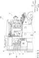
FIG. 1 is a schematic perspective view of a bagmaking and packaging apparatus in accordance with the claimed invention; -
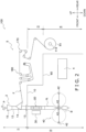
FIG. 2 is a diagram showing the schematic configuration of the bagmaking and packaging apparatus ofFIG. 1 ; -
FIG. 3 is a schematic perspective view, seen from a viewpoint different from that ofFIG. 1 , illustrating a state in which a door of the bagmaking and packaging apparatus illustrated inFIG. 1 is open; and -
FIG. 4 is an enlarged perspective view of the rear portion of the bagmaking and packaging apparatus illustrated inFIG. 1 . - An embodiment of a bagmaking and packaging apparatus in accordance with the claimed invention will now be described with reference to the drawings. It will be noted that the following description is merely a specific example of the claimed invention and is not intended to limit the technical scope of the claimed invention. It will be understood that various changes in form and detail may be made without departing from the spirit and scope of the claimed invention as set forth in the claims.
- In the following description, there are cases where expressions such as horizontal, vertical, flat, and parallel are used, and these include not only cases where that which they describe are completely horizontal, vertical, flat, or parallel but also cases where that which they describe are substantially horizontal, vertical, flat, or parallel.
- Furthermore, in the following description, there are cases where, for convenience of description, expressions such as "front (in front of)," "rear (in back of)," "upper," "lower," "left," and "right" are used to indicate directions. Unless otherwise specified, these directional expressions refer to the directions of the arrows appearing in the drawings.
- A bagmaking and
packaging apparatus 100 is what is known as a vertical pillow packaging apparatus that performs bagmaking and packaging by feeding a product P supplied from above to the inside of a tubular bag, in which a film F has been formed in a tubular shape, and transversely sealing the top and bottom of the tubular bag. - As shown in
FIG. 1 andFIG. 2 , the bagmaking andpackaging apparatus 100 includes afilm conveyance mechanism 20, aformer mechanism 3, alongitudinal sealing mechanism 30, atransverse sealing mechanism 40, afirst partition member 10, acover 16, afilm supply mechanism 5, acontrol unit 4, and asecond partition member 60. - The
former mechanism 3 receives a supply of the product P and forms in a tubular shape the sheet-like film F supplied from thefilm supply mechanism 5. - The
former mechanism 3 includes aproduct feed chute 15, atube 12, a former 14, and aformer base 13. - The
product feed chute 15 has the product P fed to it through an opening in the upper portion thereof. Theproduct feed chute 15 receives the supply of the product P from, for example, a combination weigher (not shown in the drawings) disposed above it. The combination weigher uses plural weigh hoppers to measure a predetermined weight of the product P (e.g., potato chips) and supplies the product P to the opening in the upper portion of theproduct feed chute 15. - The
tube 12 is a tubular member that extends in the up and down direction, and upper and lower ends of thetube 12 are open. Theproduct feed chute 15 is disposed in, and the product P supplied by the combination weigher is fed to, the opening in the upper end of thetube 12. - The former 14 is disposed so as to surround the
tube 12. The former 14 forms in a tubular shape the sheet-like film F supplied from thefilm supply mechanism 5 to form a tubular film Ft in which end portions of the film F in a direction orthogonal to the conveyance direction overlap each other. - The
former base 13 is a tabular member. Theformer base 13 is disposed under the former 14. The former 14 and thetube 12 are secured to theformer base 13. In the central portion of theformer base 13 is formed a through hole (not shown in the drawings) through which thetube 12 is inserted. - The
former base 13 is attached to thefirst partition member 10 described later. Specifically, theformer base 13 is attached to thefirst partition member 10 in such a way that a bottom surface of theformer base 13 is in contact with an upper surface of thefirst partition member 10. - The
film conveyance mechanism 20 conveys the film F supplied from thefilm supply mechanism 5. Specifically, thefilm conveyance mechanism 20 uses a pair of belts (not shown in the drawings) having a suction function to hold and convey the tubular film Ft downward, thereby conveying the tubular film Ft and the upstream sheet-like film F. - The
film conveyance mechanism 20 is disposed under theformer mechanism 3. More specifically, thefilm conveyance mechanism 20 is disposed under theformer base 13 of theformer mechanism 3. - The
longitudinal sealing mechanism 30 seals the tubular film Ft in its longitudinal direction. Specifically, thelongitudinal sealing mechanism 30 sandwiches the overlapping portion of the film F between itself and thetube 12 and in that state uses a heater (not shown in the drawings) that thelongitudinal sealing mechanism 30 has to heat-seal the overlapping portion of the film F. - The
longitudinal sealing mechanism 30 is disposed in front of thetube 12. Thelongitudinal sealing mechanism 30 is disposed under theformer mechanism 3. More specifically, thelongitudinal sealing mechanism 30 is disposed under theformer base 13 of theformer mechanism 3. - The
transverse sealing mechanism 40 is disposed under theformer mechanism 3. More specifically, thetransverse sealing mechanism 40 is disposed under theformer base 13 of theformer mechanism 3. Thetransverse sealing mechanism 40 is disposed under thelongitudinal sealing mechanism 30. - The
transverse sealing mechanism 40 transversely seals the tubular film Ft to make bags B containing the product P fed from theproduct feed chute 15. Specifically, thetransverse sealing mechanism 40 pinches, between a pair of sealingjaws 42 having built-in heaters, the tubular film Ft in a state in which the product P has been fed to the bottom portion of the tubular film Ft and heat-seals the tubular film Ft along a direction orthogonal to the conveyance direction to make the bags B containing the product P. - One of the sealing jaws, of the pair of sealing
jaws 42 that seal the tubular film Ft, has a built-in cutter (not shown in the drawings). Thetransverse sealing mechanism 40, when transversely sealing the tubular film Ft, uses the cutter to cut the tubular film Ft at the height direction middle position of the portion transversely sealed by the sealingjaws 42, thereby cutting the bag B containing the product P away from the trailing tubular film Ft. - The
first partition member 10 inhibits tiny matter such as seasoning from falling onto devices disposed under theformer mechanism 3, namely, thelongitudinal sealing mechanism 30 and thetransverse sealing mechanism 40. - The
first partition member 10 is disposed between the former 14 and thelongitudinal sealing mechanism 30 in the up and down direction. Thefirst partition member 10 vertically partitions a space around theformer mechanism 3 into a first space S1 on theproduct feed chute 15 side and a second space S2 on thetransverse sealing mechanism 40 side. The first space S1 is a space extending from the upper end of theproduct feed chute 15 to the undersurface of theformer base 13. The second space S2 is a space extending from the lower end of theformer base 13 to the lower end of the bagmaking andpackaging apparatus 100. - The
first partition member 10 is a tabular member. Thefirst partition member 10 extends horizontally in the front, rear, left, and right directions around theformer mechanism 3. The left and right direction width of thefirst partition member 10 is equal to the left and right direction width of the bagmaking andpackaging apparatus 100. Furthermore, thefirst partition member 10 extends from the front end of the bagmaking andpackaging apparatus 100 to the front end of thefilm supply mechanism 5. The upper surface of thefirst partition member 10 is flat. - In the front portion of the
first partition member 10, there is a through hole (not shown in the drawings) running vertically through thefirst partition member 10, and thetube 12 of theformer mechanism 3 is inserted into this through hole. It is preferred that the shape and size of the through hole be selected in such a way that the through hole is entirely covered by theformer base 13 of theformer mechanism 3 as viewed from above. The upper surface of thefirst partition member 10 and the undersurface of theformer base 13 contact each other without any gap between them in the up and down direction. - The material of the
first partition member 10 is not particularly limited, and, for example, may be stainless steel. - The
cover 16 prevents, from the standpoint of safety, workers from touching the sealing mechanisms and the like. Thecover 16 surrounds theformer mechanism 3 and extends from the upper end portion of theformer mechanism 3 to near the upper end portion of thetransverse sealing mechanism 40. Specifically, thecover 16 is disposed along, and covers, the front side, the right side, and the left surface of thefirst partition member 10. Panels forming thecover 16 are disposed in a vertical direction relative to thefirst partition member 10. The material of thecover 16 is not particularly limited and, for example, may be resin. - Hereinafter, the portion of the
cover 16 that covers the front side of theformer mechanism 3 will be called a front side cover D1, the portion that covers the right side of theformer mechanism 3 will be called a right side cover D2, and the portion that covers the left side of theformer mechanism 3 will be called a left side cover (not shown in the drawings). - The right side cover D2 is provided with a portion that does not cover the
former mechanism 3, namely, an opening C. The opening C extends from the rear end of theformer base 13 to the rear end of thefirst partition member 10 as viewed from the side. The opening C is an opening for cleaning thefirst partition member 10. - Multiple
small holes 16b are formed in the lower portions of the front side cover D1, the right side cover D2, and the left side cover. - The right side cover D2 has a
door 16a. The entire right side cover D2 may also be configured to serve as thedoor 16a. - A
part 50 of thefirst partition member 10 is attached to thedoor 16a. More specifically, the right-side front portion of thefirst partition member 10 is provided on thedoor 16a. For that reason, when thedoor 16a is opened, the right-side front portion of thefirst partition member 10 moves together with thedoor 16a to expose the entireformer mechanism 3. - The
film supply mechanism 5 holds a film roll R1 in which the sheet-like film F is wound and supplies to theformer mechanism 3 the film F paid out from the film roll R1. - The
film supply mechanism 5 is provided adjacent to, and on the rear side of, theformer mechanism 3 and supplies the sheet-like film F to theformer mechanism 3. Thefilm supply mechanism 5 includesmultiple rollers 170 and atension adjustment mechanism 180. - The
film supply mechanism 5 supplies to theformer mechanism 3 the film F paid out from the film roll R1. The film roll R1 is supported on asupport shaft 114. - The film F paid out from the film roll R1 disposed in a film supply position is guided by the
rollers 170 disposed along a predetermined film conveyance path in thefilm supply mechanism 5 and is conveyed to theformer mechanism 3. - The
tension adjustment mechanism 180, which adjusts the magnitude of the tension acting on the conveyed film F, is provided on the film conveyance path in thefilm supply mechanism 5. - The
control unit 4 is disposed under thefilm supply mechanism 5. Thecontrol unit 4 controls the operations of the various configurations of the bagmaking andpackaging apparatus 100. - The
control unit 4 has, for example, a CPU, storage units such as a main storage unit and an auxiliary storage unit, an input/output device, and various electrical circuits and electronic circuits. Thecontrol unit 4 controls the operations of each part of theformer mechanism 3 and thefilm supply mechanism 5 as a result of the CPU reading and executing programs stored in a memory. - Specifically, the
control unit 4 is electrically connected to, and controls the operations of, thefilm conveyance mechanism 20, thelongitudinal sealing mechanism 30, and thetransverse sealing mechanism 40 of theformer mechanism 3. - The
second partition member 60 inhibits tiny matter such as seasoning from falling onto devices disposed under thefilm supply mechanism 5, namely, thecontrol unit 4. - The
second partition member 60 is disposed above thecontrol unit 4. Thesecond partition member 60 vertically partitions the second space between thefilm supply mechanism 5 and thecontrol unit 4 into a third space S3 on thefilm supply mechanism 5 side and a fourth space S4 on thecontrol unit 4 side. - The
second partition member 60 is tabular. Thesecond partition member 60 extends horizontally in the front, rear, left, and right directions in the rear portion of the bagmaking andpackaging apparatus 100. The left and right direction width of thesecond partition member 60 is equal to the left and right direction width of the bagmaking andpackaging apparatus 100. Thesecond partition member 60 extends from the front end of thefilm supply mechanism 5 to the rear end of thecontrol unit 4. - The front end of the
second partition member 60 is coupled to the rear end of thefirst partition member 10. Thesecond partition member 60 is disposed in a lower position than thefirst partition member 10. Namely, thesecond partition member 60 is disposed between thefirst partition member 10 and thecontrol unit 4. Between thesecond partition member 60 and thefirst partition member 10, there is a step. The step may be a slope. - The upper surface of the
second partition member 60 is flat. - The material of the
second partition member 60 is not particularly limited and, for example, may be stainless steel. - Tiny matter such as seasoning particles falls from the connecting part between the combination weigher and the
former mechanism 3. When cleaning the bagmaking andpackaging apparatus 100, a worker inserts through the opening C in thecover 16 a tube or the like that blows out high-pressure air and, using the air blown out from the tube, blows away the tiny matter on thefirst partition member 10. - Units disposed under the
former mechanism 3, namely, thelongitudinal sealing mechanism 30 and thetransverse sealing mechanism 40, have a relatively complex structure. For that reason, when tiny matter such as seasoning particles sticks to the units, it is difficult to clean them. Furthermore, when such tiny matter sticks to the units, sealing defects and mechanical failures may occur. - The bagmaking and
packaging apparatus 100 serving as an example of the bagmaking and packaging apparatus pertaining to the claimed invention includes thefilm conveyance mechanism 20, theformer mechanism 3, thetransverse sealing mechanism 40, and thefirst partition member 10. Thefilm conveyance mechanism 20 conveys the film F. Theformer mechanism 3 includes theproduct feed chute 15 and the former 14. Theproduct feed chute 15 has the product P fed to it. The former 14 forms in a tubular shape the film F conveyed by thefilm conveyance mechanism 20. Thetransverse sealing mechanism 40 is disposed under theformer mechanism 3. Thetransverse sealing mechanism 40 transversely seals the tubular film Ft to make the bags B containing the product P fed from theproduct feed chute 15. Thefirst partition member 10 partitions the space around theformer mechanism 3 into the first space S1 and the second space S2. The first space S1 is on theproduct feed chute 15 side. The second space S2 is on thetransverse sealing mechanism 40 side. - The bagmaking and
packaging apparatus 100 has thefirst partition member 10 that partitions the space around theformer mechanism 3 into the first space S1 and the second space S2. For that reason, tiny matter can be inhibited from getting into the units disposed under theformer mechanism 3. As a result, the units are less likely to become dirty, and cleanability is enhanced. - Furthermore, deposition of the tiny matter is concentrated on the
first partition member 10, so one need only concentrate on cleaning the upper surface of thefirst partition member 10. This also enhances cleanability. - In the bagmaking and
packaging apparatus 100, theformer mechanism 3 has theformer base 13. Theformer base 13 has theproduct feed chute 15 and the former 14 attached to it. Theformer base 13 is attached to thefirst partition member 10. - In this bagmaking and
packaging apparatus 100, theformer base 13 can be used as a reference when attaching theformer mechanism 3, so it becomes easy to position the former 14 relative to thefirst partition member 10. Specifically, a worker grips theformer base 13 and installs theformer mechanism 3 so that the bottom surface of theformer base 13 is along the upper surface of thefirst partition member 10. By moving theformer base 13 horizontally on thefirst partition member 10, theformer mechanism 3 can be installed in a predetermined position on thefirst partition member 10 that is an attachment surface. - In the bagmaking and
packaging apparatus 100, the upper surface of thefirst partition member 10 is flat. In the bagmaking andpackaging apparatus 100, there is no unevenness in the upper surface of thefirst partition member 10, so it is easy to perform not only cleaning by blowing thefirst partition member 10 with an air jet but also cleaning by wiping thefirst partition member 10 with a duster cloth or the like. For that reason, cleanability is enhanced. - The bagmaking and
packaging apparatus 100 further includes thecover 16. Thecover 16 has thedoor 16a. Thecover 16 surrounds theformer mechanism 3. As shown inFIG. 3 , thepart 50 of thefirst partition member 10 is provided on thedoor 16a. - In the bagmaking and
packaging apparatus 100, thepart 50 of thefirst partition member 10 moves together with thedoor 16a to expose the entireformer mechanism 3. For that reason, there is nothing to get in the way when detaching and attaching theformer mechanism 3, and it is easy to detach and attach theformer mechanism 3. Furthermore, it is easy to access the area around theformer mechanism 3, and cleanability is enhanced. - As shown in
FIG. 1 , in the bagmaking andpackaging apparatus 100, thecover 16 is provided with the opening C. - In the bagmaking and
packaging apparatus 100, thefirst partition member 10 can be cleaned through the opening C. - As shown in
FIG. 1 andFIG. 2 , the bagmaking andpackaging apparatus 100 further includes thefilm supply mechanism 5. Thefilm supply mechanism 5 holds the film roll R1 and supplies the film F. Thecontrol unit 4 is disposed under thefilm supply mechanism 5. The bagmaking andpackaging apparatus 100 has thesecond partition member 60. Thesecond partition member 60 partitions the second space S2 between thefilm supply mechanism 5 and thecontrol unit 4 into the third space S3 and the fourth space S4. The third space S3 is on thefilm supply mechanism 5 side. The fourth space S4 is on thecontrol unit 4 side. - In the bagmaking and
packaging apparatus 100, seasoning particles can be prevented from falling onto thecontrol unit 4. - In the bagmaking and
packaging apparatus 100, the upper surface of thesecond partition member 60 is flat. - In the bagmaking and
packaging apparatus 100, there is no unevenness in the upper surface of thesecond partition member 60, so cleanability is enhanced. - Example modifications of the embodiment will be described below. The example modifications may be appropriately combined to the extent that they are not mutually contradictory.
- In the above embodiment, the upper surface of the
first partition member 10 is flat, but it is not particularly limited to this. The upper surface of thefirst partition member 10 may, for example, be a curved surface. - Likewise, the upper surface of the
second partition member 60 is also not limited to being flat. - In the above embodiment, the
first partition member 10 is horizontally disposed, but it is not particularly limited to this. Thefirst partition member 10 may, for example, be inclined from left to right. In this case, when a worker stands on the right side of and cleans the bagmaking andpackaging apparatus 100, it is easy for the worker to clean off and collect tiny matter such as seasoning particles on the right side. - Likewise, the
second partition member 60 is also not limited to being horizontally disposed. - In the above embodiment, a step is provided between the
first partition member 10 and thesecond partition member 60, but thefirst partition member 10 and thesecond partition member 60 are not particularly limited to this. Thefirst partition member 10 and thesecond partition member 60 may also be flush with each other. Namely, instead of installing thesecond partition member 60, thefirst partition member 10 may be extended rearward. In this case, cleanability is excellent. - Furthermore, the
second partition member 60 and thefirst partition member 10 may be coupled to each other in a state in which the height of the upper surface of the front end of thesecond partition member 60 and the height of the upper surface of the rear end of thefirst partition member 10 are made the same, and thesecond partition member 60 may be inclined rearward. - The above embodiment assumes that the bagmaking and
packaging apparatus 100 is manually cleaned, but the bagmaking andpackaging apparatus 100 is not particularly limited to this. As shown inFIG. 4 , the bagmaking andpackaging apparatus 100 may further includeair outlets 90 for cleaning. In this case, automatic cleaning becomes possible. - The method of forming the
air outlets 90 for cleaning is not particularly limited. Theair outlets 90 for cleaning may, for example, be formed by disposing a tube for an air jet on thesecond partition member 60. The air jet may be controlled from the bagmaking andpackaging apparatus 100 and made to execute a program such as cleaning at regular intervals or a cleaning mode. It will be noted that theair outlets 90 may also be disposed on thefirst partition member 10. - In the above embodiment, the
cover 16 also covers a range above thefirst partition member 10 and thesecond partition member 60, but the range covered by thecover 16 is not limited to this. Thecover 16 may also be configured to cover just a range under thefirst partition member 10 and thesecond partition member 60. Because of this, it becomes even easier to access thefirst partition member 10 and thesecond partition member 60, and cleanability is improved. It will be noted that in this case also, areas that pose a danger if the worker were to get caught in them, such as thetransverse sealing mechanism 40 for example, are covered, and safety is ensured. Furthermore, two bagmaking andpackaging apparatus 100 of the embodiment may be installed in parallel, and the gap between them may be closed by spacers of the same heights as thefirst partition member 10 and thesecond partition member 60, so that, for example, a worker can stand on the right side of one bagmaking andpackaging apparatus 100 and clean off tiny matter such as seasoning particles at one time toward the left side of the other bagmaking andpackaging apparatus 100, so that cleaning efficiency can be improved. - The claimed invention is useful as a bagmaking and packaging apparatus that has excellent cleanability.
-
- 3
- Former Mechanism
- 4
- Control Unit
- 5
- Film Supply Mechanism
- 10
- First Partition Member
- 13
- Former Base
- 14
- Former
- 15
- Product Feed Chute
- 16
- Cover
- 16a
- Door
- 20
- Film Conveyance Mechanism
- 40
- Transverse Sealing Mechanism
- 60
- Second Partition Member
- 90
- Air Outlets
- 100
- Bagmaking and Packaging Apparatus
- B
- Bags
- C
- Opening
- F
- Film
- P
- Product
- R1
- Film Roll
- S 1
- First Space
- S2
- Second Space
- S3
- Third Space
- S4
- Fourth Space
- Patent Document 1:
JP-A No. 2002-337817
Claims (8)
- A bagmaking and packaging apparatus, comprising:a film conveyance mechanism configured to convey a film;a former mechanism including a product feed chute to which a product is to be fed and a former configured to form the film into a tubular shape, the film to be conveyed by the film conveyance mechanism;a transverse sealing mechanism disposed under the former mechanism and the transverse sealing mechanism and being configured to transversely seal the tubular film to make bags containing the product that has been fed from the product feed chute; anda first partition member partitioning a space around the former mechanism into a first space on the product feed chute side and a second space on the transverse sealing mechanism side.
- The bagmaking and packaging apparatus of claim 1, wherein the former mechanism has a former base to which the product feed chute and the former are attached and the former base is attached to the first partition member.
- The bagmaking and packaging apparatus of claim 1 or 2, wherein an upper surface of the first partition member is flat.
- The bagmaking and packaging apparatus of any one of claims 1 to 3, further comprising a cover having a door with the cover surrounding the former mechanism in a vertical direction,
wherein a part of the first partition member is attached to the door. - The bagmaking and packaging apparatus of claim 4, wherein the cover has an opening.
- The bagmaking and packaging apparatus of any one of claims 1 to 5, further comprising air outlets for cleaning.
- The bagmaking and packaging apparatus of any one of claims 1 to 6, further comprising a film supply mechanism configured to hold a film roll and to supply the film,wherein a control unit is disposed under the film supply mechanism, andthe bagmaking and packaging apparatus has a second partition member partitioning the second space between the film supply mechanism and the control unit into a third space on the film supply mechanism side and a fourth space on the control unit side.
- The bagmaking and packaging apparatus of claim 7, wherein an upper surface of the second partition member is flat.
Applications Claiming Priority (1)
| Application Number | Priority Date | Filing Date | Title |
|---|---|---|---|
| JP2022196189A JP2024082383A (en) | 2022-12-08 | 2022-12-08 | Bag making and packaging equipment |
Publications (2)
| Publication Number | Publication Date |
|---|---|
| EP4382435A1 true EP4382435A1 (en) | 2024-06-12 |
| EP4382435B1 EP4382435B1 (en) | 2025-10-29 |
Family
ID=88837415
Family Applications (1)
| Application Number | Title | Priority Date | Filing Date |
|---|---|---|---|
| EP23210003.2A Active EP4382435B1 (en) | 2022-12-08 | 2023-11-15 | Bagmaking and packaging apparatus |
Country Status (4)
| Country | Link |
|---|---|
| US (1) | US12448161B2 (en) |
| EP (1) | EP4382435B1 (en) |
| JP (1) | JP2024082383A (en) |
| AU (1) | AU2023270252B2 (en) |
Citations (5)
| Publication number | Priority date | Publication date | Assignee | Title |
|---|---|---|---|---|
| JP2002337817A (en) | 2001-05-21 | 2002-11-27 | Ishida Co Ltd | Bag making and packaging machine |
| US20030093971A1 (en) * | 2000-08-18 | 2003-05-22 | Emanuele Terminella | Vertical form, fill and seal packaging machine |
| AU2018204221A1 (en) * | 2017-07-07 | 2019-01-24 | ULMA Packaging, S.Coop. | Vertical packaging machine |
| EP3461749A2 (en) * | 2017-09-27 | 2019-04-03 | Tetra Laval Holdings & Finance S.A. | A packaging apparatus for forming sealed packages |
| AU2022201663A1 (en) * | 2021-03-11 | 2022-09-29 | Ishida Co., Ltd. | Bag making and packaging device and tube member for bag making and packaging device |
Family Cites Families (6)
| Publication number | Priority date | Publication date | Assignee | Title |
|---|---|---|---|---|
| US3488914A (en) * | 1965-05-28 | 1970-01-13 | Fmc Corp | Package filling and sealing system |
| JP4408489B2 (en) * | 1999-08-16 | 2010-02-03 | 株式会社イシダ | Bag making and packaging machine |
| AU2003903509A0 (en) * | 2003-07-08 | 2003-07-24 | Tna Australia Pty Limited | A packaging machine former support |
| JP5918980B2 (en) * | 2011-02-04 | 2016-05-18 | 株式会社イシダ | Bag making and packaging machine |
| JP6742625B2 (en) * | 2016-04-28 | 2020-08-19 | 株式会社イシダ | Packaging equipment |
| EP3514074A4 (en) * | 2016-09-16 | 2019-07-31 | Ishida Co., Ltd. | WEIGHING / PACKING DEVICE |
-
2022
- 2022-12-08 JP JP2022196189A patent/JP2024082383A/en active Pending
-
2023
- 2023-11-14 US US18/508,243 patent/US12448161B2/en active Active
- 2023-11-15 EP EP23210003.2A patent/EP4382435B1/en active Active
- 2023-11-22 AU AU2023270252A patent/AU2023270252B2/en active Active
Patent Citations (5)
| Publication number | Priority date | Publication date | Assignee | Title |
|---|---|---|---|---|
| US20030093971A1 (en) * | 2000-08-18 | 2003-05-22 | Emanuele Terminella | Vertical form, fill and seal packaging machine |
| JP2002337817A (en) | 2001-05-21 | 2002-11-27 | Ishida Co Ltd | Bag making and packaging machine |
| AU2018204221A1 (en) * | 2017-07-07 | 2019-01-24 | ULMA Packaging, S.Coop. | Vertical packaging machine |
| EP3461749A2 (en) * | 2017-09-27 | 2019-04-03 | Tetra Laval Holdings & Finance S.A. | A packaging apparatus for forming sealed packages |
| AU2022201663A1 (en) * | 2021-03-11 | 2022-09-29 | Ishida Co., Ltd. | Bag making and packaging device and tube member for bag making and packaging device |
Also Published As
| Publication number | Publication date |
|---|---|
| JP2024082383A (en) | 2024-06-20 |
| AU2023270252A1 (en) | 2024-06-27 |
| AU2023270252B2 (en) | 2025-07-03 |
| US12448161B2 (en) | 2025-10-21 |
| EP4382435B1 (en) | 2025-10-29 |
| US20240190597A1 (en) | 2024-06-13 |
Similar Documents
| Publication | Publication Date | Title |
|---|---|---|
| US7877966B2 (en) | Machine for forming, filling and closing bags with a bag lifting device | |
| US3035754A (en) | Bag construction | |
| AU2016395149B2 (en) | Boxing device | |
| JP5591840B2 (en) | Method for dispensing and packaging polysilicon debris | |
| EP3514074A1 (en) | Weighing/packaging device | |
| CN107207105B (en) | Metering and packaging system | |
| EP1077176B1 (en) | Bagging and packaging machine capable of sufficiently filling an inert gas into bags | |
| CN104620689A (en) | Tape feeder and tape feeding method for chip mounter | |
| EP4382435B1 (en) | Bagmaking and packaging apparatus | |
| US20200131023A1 (en) | Pillow fill machine | |
| US20100323868A1 (en) | Bag-making and packaging apparatus | |
| EP3432038A1 (en) | Inspection unit support device and inspection apparatus | |
| JP3202430U (en) | Transport device | |
| CN118323532A (en) | Bag making and packaging equipment and metering and packaging systems | |
| CN101687554B (en) | Packing machine | |
| CN120482480A (en) | Boxing device | |
| JP6305836B2 (en) | Article regulating device and combination weigher provided with the same | |
| US20140179502A1 (en) | Packaging machine former | |
| JP7514525B2 (en) | Vertical form fill packaging machine | |
| JP2025097352A (en) | Combination balance | |
| JP5509260B2 (en) | Small bag continuum folding device | |
| JP5568296B2 (en) | Bag making and filling cylinder in vertical bag making and filling machine | |
| JP6759052B2 (en) | Goods supply device for combination scales | |
| JP2015001508A (en) | Vibrating feeder and combination scale equipped with the same | |
| JP2009173301A (en) | Dust collection mechanism in filling chute of automatic packaging machine |
Legal Events
| Date | Code | Title | Description |
|---|---|---|---|
| PUAI | Public reference made under article 153(3) epc to a published international application that has entered the european phase |
Free format text: ORIGINAL CODE: 0009012 |
|
| STAA | Information on the status of an ep patent application or granted ep patent |
Free format text: STATUS: REQUEST FOR EXAMINATION WAS MADE |
|
| 17P | Request for examination filed |
Effective date: 20231115 |
|
| AK | Designated contracting states |
Kind code of ref document: A1 Designated state(s): AL AT BE BG CH CY CZ DE DK EE ES FI FR GB GR HR HU IE IS IT LI LT LU LV MC ME MK MT NL NO PL PT RO RS SE SI SK SM TR |
|
| GRAP | Despatch of communication of intention to grant a patent |
Free format text: ORIGINAL CODE: EPIDOSNIGR1 |
|
| STAA | Information on the status of an ep patent application or granted ep patent |
Free format text: STATUS: GRANT OF PATENT IS INTENDED |
|
| RIC1 | Information provided on ipc code assigned before grant |
Ipc: B65B 9/20 20120101ALI20250423BHEP Ipc: B65B 5/02 20060101AFI20250423BHEP |
|
| INTG | Intention to grant announced |
Effective date: 20250527 |
|
| GRAS | Grant fee paid |
Free format text: ORIGINAL CODE: EPIDOSNIGR3 |
|
| GRAA | (expected) grant |
Free format text: ORIGINAL CODE: 0009210 |
|
| STAA | Information on the status of an ep patent application or granted ep patent |
Free format text: STATUS: THE PATENT HAS BEEN GRANTED |
|
| AK | Designated contracting states |
Kind code of ref document: B1 Designated state(s): AL AT BE BG CH CY CZ DE DK EE ES FI FR GB GR HR HU IE IS IT LI LT LU LV MC ME MK MT NL NO PL PT RO RS SE SI SK SM TR |
|
| REG | Reference to a national code |
Ref country code: CH Ref legal event code: F10 Free format text: ST27 STATUS EVENT CODE: U-0-0-F10-F00 (AS PROVIDED BY THE NATIONAL OFFICE) Effective date: 20251029 Ref country code: GB Ref legal event code: FG4D |
|
| REG | Reference to a national code |
Ref country code: DE Ref legal event code: R096 Ref document number: 602023008014 Country of ref document: DE |
|
| REG | Reference to a national code |
Ref country code: NL Ref legal event code: FP Ref country code: IE Ref legal event code: FG4D |
|
| PGFP | Annual fee paid to national office [announced via postgrant information from national office to epo] |
Ref country code: AT Payment date: 20260113 Year of fee payment: 3 |
|
| PG25 | Lapsed in a contracting state [announced via postgrant information from national office to epo] |
Ref country code: ES Free format text: LAPSE BECAUSE OF FAILURE TO SUBMIT A TRANSLATION OF THE DESCRIPTION OR TO PAY THE FEE WITHIN THE PRESCRIBED TIME-LIMIT Effective date: 20251029 |
|
| REG | Reference to a national code |
Ref country code: LT Ref legal event code: MG9D |
|
| PG25 | Lapsed in a contracting state [announced via postgrant information from national office to epo] |
Ref country code: NO Free format text: LAPSE BECAUSE OF FAILURE TO SUBMIT A TRANSLATION OF THE DESCRIPTION OR TO PAY THE FEE WITHIN THE PRESCRIBED TIME-LIMIT Effective date: 20260129 |
|
| PGFP | Annual fee paid to national office [announced via postgrant information from national office to epo] |
Ref country code: DE Payment date: 20251222 Year of fee payment: 3 |
|
| PG25 | Lapsed in a contracting state [announced via postgrant information from national office to epo] |
Ref country code: FI Free format text: LAPSE BECAUSE OF FAILURE TO SUBMIT A TRANSLATION OF THE DESCRIPTION OR TO PAY THE FEE WITHIN THE PRESCRIBED TIME-LIMIT Effective date: 20251029 Ref country code: AT Free format text: LAPSE BECAUSE OF FAILURE TO SUBMIT A TRANSLATION OF THE DESCRIPTION OR TO PAY THE FEE WITHIN THE PRESCRIBED TIME-LIMIT Effective date: 20251029 Ref country code: HR Free format text: LAPSE BECAUSE OF FAILURE TO SUBMIT A TRANSLATION OF THE DESCRIPTION OR TO PAY THE FEE WITHIN THE PRESCRIBED TIME-LIMIT Effective date: 20251029 |
|
| REG | Reference to a national code |
Ref country code: AT Ref legal event code: MK05 Ref document number: 1851349 Country of ref document: AT Kind code of ref document: T Effective date: 20251029 |
|
| PG25 | Lapsed in a contracting state [announced via postgrant information from national office to epo] |
Ref country code: RS Free format text: LAPSE BECAUSE OF FAILURE TO SUBMIT A TRANSLATION OF THE DESCRIPTION OR TO PAY THE FEE WITHIN THE PRESCRIBED TIME-LIMIT Effective date: 20260129 |
|
| PG25 | Lapsed in a contracting state [announced via postgrant information from national office to epo] |
Ref country code: IS Free format text: LAPSE BECAUSE OF FAILURE TO SUBMIT A TRANSLATION OF THE DESCRIPTION OR TO PAY THE FEE WITHIN THE PRESCRIBED TIME-LIMIT Effective date: 20260228 |
|
| PG25 | Lapsed in a contracting state [announced via postgrant information from national office to epo] |
Ref country code: PT Free format text: LAPSE BECAUSE OF FAILURE TO SUBMIT A TRANSLATION OF THE DESCRIPTION OR TO PAY THE FEE WITHIN THE PRESCRIBED TIME-LIMIT Effective date: 20260302 |
|
| PG25 | Lapsed in a contracting state [announced via postgrant information from national office to epo] |
Ref country code: PL Free format text: LAPSE BECAUSE OF FAILURE TO SUBMIT A TRANSLATION OF THE DESCRIPTION OR TO PAY THE FEE WITHIN THE PRESCRIBED TIME-LIMIT Effective date: 20251029 |
|
| PG25 | Lapsed in a contracting state [announced via postgrant information from national office to epo] |
Ref country code: LV Free format text: LAPSE BECAUSE OF FAILURE TO SUBMIT A TRANSLATION OF THE DESCRIPTION OR TO PAY THE FEE WITHIN THE PRESCRIBED TIME-LIMIT Effective date: 20251029 |
|
| PG25 | Lapsed in a contracting state [announced via postgrant information from national office to epo] |
Ref country code: BG Free format text: LAPSE BECAUSE OF FAILURE TO SUBMIT A TRANSLATION OF THE DESCRIPTION OR TO PAY THE FEE WITHIN THE PRESCRIBED TIME-LIMIT Effective date: 20251029 |