EP4382320A1 - Method and system for detecting swapped tires on a vehicle - Google Patents
Method and system for detecting swapped tires on a vehicle Download PDFInfo
- Publication number
- EP4382320A1 EP4382320A1 EP23214450.1A EP23214450A EP4382320A1 EP 4382320 A1 EP4382320 A1 EP 4382320A1 EP 23214450 A EP23214450 A EP 23214450A EP 4382320 A1 EP4382320 A1 EP 4382320A1
- Authority
- EP
- European Patent Office
- Prior art keywords
- signature data
- signal
- initial
- control unit
- tires
- Prior art date
- Legal status (The legal status is an assumption and is not a legal conclusion. Google has not performed a legal analysis and makes no representation as to the accuracy of the status listed.)
- Pending
Links
Images


Classifications
-
- B—PERFORMING OPERATIONS; TRANSPORTING
- B60—VEHICLES IN GENERAL
- B60C—VEHICLE TYRES; TYRE INFLATION; TYRE CHANGING; CONNECTING VALVES TO INFLATABLE ELASTIC BODIES IN GENERAL; DEVICES OR ARRANGEMENTS RELATED TO TYRES
- B60C23/00—Devices for measuring, signalling, controlling, or distributing tyre pressure or temperature, specially adapted for mounting on vehicles; Arrangement of tyre inflating devices on vehicles, e.g. of pumps or of tanks; Tyre cooling arrangements
- B60C23/02—Signalling devices actuated by tyre pressure
- B60C23/04—Signalling devices actuated by tyre pressure mounted on the wheel or tyre
- B60C23/0408—Signalling devices actuated by tyre pressure mounted on the wheel or tyre transmitting the signals by non-mechanical means from the wheel or tyre to a vehicle body mounted receiver
- B60C23/0415—Automatically identifying wheel mounted units, e.g. after replacement or exchange of wheels
- B60C23/0416—Automatically identifying wheel mounted units, e.g. after replacement or exchange of wheels allocating a corresponding wheel position on vehicle, e.g. front/left or rear/right
-
- B—PERFORMING OPERATIONS; TRANSPORTING
- B60—VEHICLES IN GENERAL
- B60C—VEHICLE TYRES; TYRE INFLATION; TYRE CHANGING; CONNECTING VALVES TO INFLATABLE ELASTIC BODIES IN GENERAL; DEVICES OR ARRANGEMENTS RELATED TO TYRES
- B60C23/00—Devices for measuring, signalling, controlling, or distributing tyre pressure or temperature, specially adapted for mounting on vehicles; Arrangement of tyre inflating devices on vehicles, e.g. of pumps or of tanks; Tyre cooling arrangements
- B60C23/02—Signalling devices actuated by tyre pressure
- B60C23/04—Signalling devices actuated by tyre pressure mounted on the wheel or tyre
- B60C23/0408—Signalling devices actuated by tyre pressure mounted on the wheel or tyre transmitting the signals by non-mechanical means from the wheel or tyre to a vehicle body mounted receiver
- B60C23/0422—Signalling devices actuated by tyre pressure mounted on the wheel or tyre transmitting the signals by non-mechanical means from the wheel or tyre to a vehicle body mounted receiver characterised by the type of signal transmission means
- B60C23/0433—Radio signals
- B60C23/0435—Vehicle body mounted circuits, e.g. transceiver or antenna fixed to central console, door, roof, mirror or fender
- B60C23/0437—Means for detecting electromagnetic field changes not being part of the signal transmission per se, e.g. strength, direction, propagation or masking
Definitions
- the invention relates generally to a method and a system for detecting swapped tires on a vehicle and, more particularly, to a method and a system that uses signal strength indicators of signals received from tire-mounted transmitters at a control unit, in order to detect when tires on a vehicle have been swapped.
- Tires for automotive vehicles are nowadays equipped with sensor units, such as for example pressure sensors that are attached to an innerliner of the tire.
- the sensors measure a parameter of the tire, such as its inflation pressure, and communicate the measured value wirelessly to a telematics control unit of the vehicle.
- This control unit receives signals carrying the measured value from each of the vehicle's tires and is configured to monitor all sensed parameters, raise alerts if predetermined operating values of the parameters are exceeded, to notify the driver, or to send maintenance alerts to a vehicle fleet operator.
- the correct identification of a tire's position on the vehicle is crucial for these tire related services. If tires are swapped during a maintenance operation, and the new positions on the vehicle are not properly registered at the control unit, this may lead to erroneous notifications, as the data gathered over time from a given position will correspond to different tires, but will be attributed to the same registered tire by the control unit.
- US 9 278 589 B2 proposes to compare the signal strength of a signal that is received from a tire at a control unit, to a previously recorded signal strength, which is referred to as training data, in order to detect a change of position of the tire.
- training data a previously recorded signal strength
- the document remains silent as to how to obtain sufficient training data in practice, which is particularly problematic for multi-axle vehicles due to the large number of tires, and thus the large number of possible tire swaps that one should be able to detect.
- the invention relates to a method in accordance with claim 1, to a system in accordance with claim 8 and to a control unit in accordance with claim 12.
- a computer-implemented method for detecting a swap of tires on a vehicle including a set of tires mounted in a plurality of available mounting positions of the vehicle is provided. Each tire is equipped with a signal transmitter. The method comprises the steps of:
- the training data set comprises matched records, in which the initial signal signature data is associated with the set of corresponding initial mounting positions, and mismatched records, which are generated by a processor by associating the initial signal signature data with a plurality of sets of mounting positions that differ from the set of initial mounting positions.
- the use of a training data set with matched records and with mismatched records may be referred to as virtualization.
- obtaining the initial signal signature data may comprise obtaining statistics of received signal strength indicator (RSSI) levels for each of the received signals over time, while the tires are mounted at their respective initial mounting positions.
- the input signal signature data may preferably comprise statistics of RSSI levels for the signals received from the signal transmitters of the tires.
- the statistics of RSSI levels may preferably be provided by a set of parameters describing a respectively corresponding RSSI level distribution.
- the step of training a machine learning algorithm may comprise a preliminary step of selecting a machine learning algorithm from a set of candidate machine learning algorithms, wherein a genetic algorithm selects a candidate machine learning algorithm based on the accuracy it provides in correctly classifying signal signature data.
- the trained machine learning algorithm provides a probability between 0 and 1, wherein the extreme values correspond to the input signal signature data being accurately classified as corresponding to the initial signal signature data, or not.
- the tire swap detection signal may preferably indicate a tire swap if the probability of the input signal signature data being accurately classified as not corresponding to the initial signal signature data is above a predetermined threshold value.
- more input signal signature data may be obtained and classified if the probability of available input signal signature data being accurately classified as not corresponding to the initial signal signature data is below a predetermined threshold value.
- the tire swap detection signal may preferably indicate a tire swap if input signal signature data obtained during a predetermined amount of time is repeatedly classified as not corresponding to the initial signal signature data.
- the available mounting positions of the vehicle correspond to positions of axles of the vehicle.
- a tire swap detection system comprises a control unit and a set of tires mounted in a plurality of available mounting positions of a vehicle, each tire being equipped with a signal transmitter.
- the control unit comprises a signal receiver for receiving signals from the signal transmitters, a first memory element for storing initial mounting positions of the tires and a second memory element for storing initial signal signature data, the initial signal signature data having been obtained by receiving, at the signal receiver, signals from the signal transmitters while the tires are mounted at their respective initial mounting positions.
- the control unit further comprises a trained machine learning algorithm configured to classify input signal signature data, obtained by receiving signals from the signal transmitters of the tires, as either corresponding to the initial signal signature data or not, and the control unit is further configured to generate a tire swap detection signal if input signature data is classified as not corresponding to the initial signal signature data.
- the machine learning algorithm may have been trained using a training data set comprising matched records, in which the initial signal signature data is associated with the set of corresponding initial mounting positions, and mismatched records, which are generated by a processor by associating the initial signal signature data with a plurality of sets of mounting positions that differ from the set of initial mounting positions.
- the control unit may preferably be arranged halfway between a front and a rear axle of the vehicle.
- control unit may be arranged closer to either one of the front or rear axles of the vehicle.
- control unit may be arranged on a longitudinal middle axis of the vehicle.
- a control unit for a vehicle is proposed.
- the control unit is configured to generate a tire swap detection signal. It comprises a signal receiver for receiving signals from signal transmitters of tires, a first memory element for storing initial mounting positions of the tires on the vehicle and a second memory element for storing initial signal signature data, the initial signal signature data having been obtained by receiving, at the signal receiver, signals from the signal transmitters while the tires are mounted at their respective initial mounting positions on the vehicle.
- the control unit further comprises a trained machine learning algorithm configured to classify input signal signature data, obtained by receiving signals from the signal transmitters of the tires, as either corresponding to the initial signal signature data or not.
- the control unit is further configured to generate a tire swap detection signal if input signature data is classified as not corresponding to the initial signal signature data.
- the initial signal signature data may be obtained by generating, at the control unit, statistics of received signal strength indicator (RSSI) levels for each of the received signals over time, while the tires are mounted at their respective initial mounting positions, and wherein the input signal signature data comprises statistics of RSSI levels for the signals received from the signal transmitters of the tires.
- RSSI received signal strength indicator
- the control unit may preferably further comprise a processor configured to select a machine learning algorithm from a set of candidate machine learning algorithms, wherein a genetic algorithm selects a candidate machine learning algorithm based on the accuracy it provides in correctly classifying signal signature data.
- RSSI Received Signal Strength Indicator. It is a measurement of the power present in a received radio signal, independently of the information comprised in the signal.
- Longitudinal is used to designate the main back-to-forth axis of a vehicle.
- Signal transmitter is used to designate any transmitter or sensor of a tire, which is capable of transmitting radio signals to a control unit of a vehicle.
- Machine learning algorithm designates a class of algorithms for automatically classifying data. This may include an artificial neural network, in which several layers of nodes, each performing detection routines on the input signal, are interconnected in order to provide an output signal, which identifies a predetermined class to which the input signal belongs.
- Training data designates data that is representative of the classes that the machine learning algorithm should classify.
- the training data comprises labelled data records, wherein each record is a priori known and labelled to belong to a given class.
- Training a machine learning algorithm means using the training data to tune parameters of the machine learning algorithm (for example parameters of the nodes of a generic artificial neural network), thereby enabling the machine learning algorithm to accurately classify an unknown input signal once the training phase has been completed.
- parameters of the machine learning algorithm for example parameters of the nodes of a generic artificial neural network
- validation data is used as test input, in order to make sure that the machine learning algorithm operates as desired.
- Genetic algorithm designates an optimization algorithm for solving both constrained and unconstrained optimization problems.
- a genetic algorithm is based on the principle of natural selection, the process that drives biological evolution. The genetic algorithm repeatedly modifies a population of candidate solutions. At each step, the genetic algorithm selects individuals from the current population to be "parents” by determining whether the corresponding solution, applied to the problem at hand, improves on previously determined solutions. The selected parents are used to produce the "children” for the next generation. The children candidate solutions inherit the properties, or parameters, of their parents, with a limited number of random modifications. Over successive generations, the population of candidate solutions to the optimization problem "evolves" toward a close-to-optimal solution.
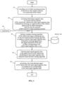
- Figure 1 provides an overview of the main steps of the proposed swap detection method, while Figure 2 shows corresponding structure in the proposed swap detection system.
- the tires 10, 20, 30, 40, 50, 60 of a vehicle are equipped with at least one sensor 12, 22, 32, 42, 52, 62 that communicates a parameter 14, 24, 34, 44, 54, 64 of the tire, such as an inflation pressure, to a control unit 100 of the vehicle using a wireless data communication channel. It is proposed to use a Received Signal Strength Indicator, RSSI, which is readily available at the receiving control unit 100, to characterize each signal transmission 14, 24, 34, 44, 54, 64 from a given tire 10, 20, 30, 40, 50, 60, independently of the information that is carried by the received signal. Only the distributions of RSSI levels for each received signal are used.
- RSSI Received Signal Strength Indicator
- Signals received from each tire position have different RSSI level distributions owing to their differing distances to the control unit receiving the signals, owing to the noise inflicted by their individual radio environments and owing to intrinsic features of the respective transmitters.
- a large number of training data relating to both classes that need to be detected is required.
- a control unit 100 typically registers an initially known set of tires 10, 20, 30, 40, 50, 60 to a set of initially known positions R1, R2, R3, L1, L2, L3 respectively. If no tires are swapped, this information remains correctly registered at the control unit. However, if tires are swapped without notifying the control unit, a mismatch between the recorded positions at the control unit, and the actual positions of tires occurs, so that the control unit is no longer able to accurately attribute a signal received from one of the available positions R1, R2, R3, L1, L2, L3 to a tire actually mounted at that position.
- FIG 3 provides a more detailed view of the control unit 100 shown in Figure 2 . While the vehicle shown in Figure 2 has six tires distributed on three axles, this is for the purpose of illustration only, and the proposed method straightforwardly applies to different pluralities of tire position and/or vehicle axles.
- the set of initial mounting positions R1, R2, R3, L1, L2, L3 of the vehicle's tires 10, 20, 30, 40, 50, 60 is recorded 112 in a first memory element 110 of the control unit 100.
- the memory element may for example comprise solid state memory capacity or any other memory element known in the art.
- Initial signal signature data 122 is recorded in a second memory element 120 of the control unit 100 during a further method step 02.
- the initial signal signature 122 data is obtained by receiving, at a signal receiver 130 of the vehicle, the signals 14, 24, 34, 44, 54, 64 from the signal transmitters 12, 22, 32, 42, 52, 62 while the tires 10, 20, 30, 40, 50, 60 are mounted at their respective initial mounting positions R1, R2, R3, L1, L2, L3.
- the obtained initial signal signature data 112 corresponds to the correctly matched configuration of the tires versus their respective actual mounting positions.
- a large data set 122 is obtained in memory element 120.
- matched data records 142 are made available to a training data set 140.
- a processor 150 further generates mismatched records 144, in which data from the large data set 122 is purposefully mismatched to tire positions 113 that do not correspond to the accurate actual positions of the tires.
- the mismatched tire positions 113 may record tire 60 in position R1 and tire 10 in positions L3, while other positions remain unchanged.
- the signal signature data 122 obtained from position R1 and recorded in the memory element 120 was actually transmitted from tire 10, while the corresponding data obtained from position L3 was transmitted from tire 60, so that mismatching the artificially generated tire positions 113 to the initial signal signature data simulates data obtained following a simulated swap of tires 10 and 60 respectively.
- Such resulting mismatched records 144 are made available to the training data set 140.
- all available permutations of tire positions 113 are generated by the processor 150 and combined with the initial signal signature data 122 in order to generate a large number of mismatched records 144.
- the training data set 140 therefore comprises a large number of training records 142 that correspond to the class "no swapped tire detected” and a large number of training records 144 that correspond to the class "swapped tire detected", even though no actual swap may have occurred as yet.
- Virtualization which is the use of matched data records 142 and mismatched records 144 in the training data set 140, is indicated at step 06 in Figure 3 .
- a machine learning algorithm 160 run by the processor 150 of the control unit 100 is trained using this training data set 140, so that the trained machine learning algorithm 160 is enabled to classify input signal signature data 001, obtained by receiving signals from the signal transmitters of the tires (while the tires are either in their recorded positions, or not), as either corresponding to the initial signal signature data 122, or not.
- step 04 once the machine learning algorithm 140 has been specialized through training, yet unclassified input signal signature data 001 is obtained at the signal receiver 130 and classified using the trained machine learning algorithm 140.
- a tire swap detection signal 171 is generated at the control unit 100 at step 05.
- the signal 171 is preferably transmitted on a vehicle communication bus by a transmitter 170 for further processing and/or communication to the vehicle fleet owner.
- the initial signal signature data 122 and the input signal signature data 001 are preferably obtained by gathering, from the signal receiver 130, RSSI levels for each of the received signals over time. This results in a statistical distribution of RSSI levels for signals received from each available mounting position, with increased accuracy as the number of received signals increases over time.
- the RSSI level distribution making up the signal signatures 112,001 may for example be stored using a set of seven parameters each, specifying for example the count of received signals from a given position, the corresponding mean RSSI level, and corresponding quantile values corresponding to 10, 25, 50, 75 and 90 percent of the corresponding RSSI levels.
- the received signals are cleaned by eliminating those signals that were obtained while the vehicle was at rest from the measurements.
- RSSI level distributions While other representations of RSSI level distributions are not excluded by the current invention, by limiting the number of parameters per signal signature to seven, a limited number of learning parameters is fed into the machine learning algorithm 160 during training, which therefore requires a limited amount of processing power and energy.
- the previously described method comprises an additional step 03A as illustrated in Figure 4 .
- the corresponding structure is illustrated in Figure 5 .
- a set of candidate generic machine learning algorithms 160A, 160B, 160C is provided in a memory element.
- a larger plurality of machine learning algorithms may be provided, and it is preferred that fifty candidate machine learning algorithms are provided, wherein each machine learning algorithm is a generic classifier as known in the art, having a given number of neural network layers, nodes per layers, interconnections between nodes, etc...
- the processor 150 then executes a genetic algorithm 155 in order to determine a classifier among the candidates that performs best.
- each of the fifty first-generation candidate machine learning algorithms 160A, 160B, 160C are trained using the training data 140 that has been generated as previously described. Their classification accuracy is then evaluated and the best 20% are retained for evolving into a next generation of candidate machine learning algorithms. A new population of fifty candidate machine learning algorithms of the second generation is generated by recombining features of the retained first generation candidates. This approach may be repeated, by way of a non-limiting example, for 100 generation.
- Figure 6 shows an alternate configuration to the configuration shown in Figure 2 .
- the control unit 100 of the system 1000 is provided closer to the vehicle's front axle than to its rear axle, while it is arranged on a middle longitudinal axis of the vehicle, shown as a dash-dotted line.
- Such an asymmetrical positioning of the control unit 100 relative to the vehicle's axles may improve the described classification accuracy, as the RSSI levels obtained from the front and rear axle mounted tires will vary more significantly and are thus more clearly discernable by the machine learning algorithm. While in the symmetrical arrangement of Figure 2 , a classification accuracy in the range of 65 to 90% has been observed, the asymmetrical arrangement improved the accuracy by about 10%.
- the machine learning algorithm may be trained to provide a probability value between 0 and 1 indicating the probability that a swapped tire has been detected, or not.
- the tire swap detection signal 171 may only be sent by the control unit 100 if the probability that a swapped tire has been detected is larger than a user-defined predetermined threshold probability value.
- first detection probabilities obtained by the proposed are low and below a user-defined predetermined threshold probability value
- further second detection probabilities from further input signal signature data 001 should be obtained, for example during several more days, and be considered in addition to the first detection probabilities.
- Virtualization which is the above-described use of a training data set with matched records and with mismatched records, may desirably reduce issues stemming from insufficient data sets in the detection of tire swap.
Landscapes
- Engineering & Computer Science (AREA)
- Mechanical Engineering (AREA)
- Physics & Mathematics (AREA)
- Electromagnetism (AREA)
- Arrangements For Transmission Of Measured Signals (AREA)
Abstract
Description
- The invention relates generally to a method and a system for detecting swapped tires on a vehicle and, more particularly, to a method and a system that uses signal strength indicators of signals received from tire-mounted transmitters at a control unit, in order to detect when tires on a vehicle have been swapped.
- Tires for automotive vehicles are nowadays equipped with sensor units, such as for example pressure sensors that are attached to an innerliner of the tire. The sensors measure a parameter of the tire, such as its inflation pressure, and communicate the measured value wirelessly to a telematics control unit of the vehicle. This control unit receives signals carrying the measured value from each of the vehicle's tires and is configured to monitor all sensed parameters, raise alerts if predetermined operating values of the parameters are exceeded, to notify the driver, or to send maintenance alerts to a vehicle fleet operator.
- The correct identification of a tire's position on the vehicle is crucial for these tire related services. If tires are swapped during a maintenance operation, and the new positions on the vehicle are not properly registered at the control unit, this may lead to erroneous notifications, as the data gathered over time from a given position will correspond to different tires, but will be attributed to the same registered tire by the control unit.
- In large fleets, for example fleets of multi-axle transport vehicles, the number of tire swaps is large. It is therefore important to reliably identify tire swaps, in order for the related notification services to provide reliable data to the fleet's owner of the tire's state.
-
US 9 278 589 B2 - There remains a need to provide a reliable automatic detection system of a tire swap or exchange on vehicles, which remains robust independently of the number of the vehicle's axles, and which does not require dedicated transmissions from the tire's sensors for the purpose of detecting a tire swap, as theses sensor rely on limited battery capacity.
- The invention relates to a method in accordance with claim 1, to a system in accordance with claim 8 and to a control unit in accordance with
claim 12. - Dependent claims refer to preferred embodiments of the invention.
- In accordance with a preferred aspect of the invention, a computer-implemented method for detecting a swap of tires on a vehicle including a set of tires mounted in a plurality of available mounting positions of the vehicle is provided. Each tire is equipped with a signal transmitter. The method comprises the steps of:
- recording a set of initial mounting positions of the tires in a first memory element of a control unit of the vehicle;
- providing initial signal signature data in a second memory element of the control unit, wherein the initial signal signature data is obtained by receiving, at a signal receiver of the vehicle, signals from the signal transmitters while the tires are mounted at their respective initial mounting positions;
- training a machine learning algorithm of the control unit using a training data set, so that the trained machine learning algorithm is enabled to classify input signal signature data, obtained by receiving signals from the signal transmitters of the tires, as either corresponding to the initial signal signature data, or not;
- obtaining input signal signature data at the signal receiver of the vehicle and classifying the input signal signature data using the trained machine learning algorithm, and
- generating a tire swap detection signal at the control unit if the input signal signature data is classified as not corresponding to the initial signal signature data;
- The training data set comprises matched records, in which the initial signal signature data is associated with the set of corresponding initial mounting positions, and mismatched records, which are generated by a processor by associating the initial signal signature data with a plurality of sets of mounting positions that differ from the set of initial mounting positions. The use of a training data set with matched records and with mismatched records may be referred to as virtualization.
- Preferably, obtaining the initial signal signature data may comprise obtaining statistics of received signal strength indicator (RSSI) levels for each of the received signals over time, while the tires are mounted at their respective initial mounting positions. The input signal signature data may preferably comprise statistics of RSSI levels for the signals received from the signal transmitters of the tires.
- The statistics of RSSI levels may preferably be provided by a set of parameters describing a respectively corresponding RSSI level distribution.
- Preferably, the step of training a machine learning algorithm may comprise a preliminary step of selecting a machine learning algorithm from a set of candidate machine learning algorithms, wherein a genetic algorithm selects a candidate machine learning algorithm based on the accuracy it provides in correctly classifying signal signature data.
- It may further be preferred that the trained machine learning algorithm provides a probability between 0 and 1, wherein the extreme values correspond to the input signal signature data being accurately classified as corresponding to the initial signal signature data, or not.
- The tire swap detection signal may preferably indicate a tire swap if the probability of the input signal signature data being accurately classified as not corresponding to the initial signal signature data is above a predetermined threshold value.
- Preferably, more input signal signature data may be obtained and classified if the probability of available input signal signature data being accurately classified as not corresponding to the initial signal signature data is below a predetermined threshold value.
- The tire swap detection signal may preferably indicate a tire swap if input signal signature data obtained during a predetermined amount of time is repeatedly classified as not corresponding to the initial signal signature data.
- It may be preferred that the available mounting positions of the vehicle correspond to positions of axles of the vehicle.
- In accordance with a further preferred aspect of the invention, a tire swap detection system is proposed. The tire swap detection system comprises a control unit and a set of tires mounted in a plurality of available mounting positions of a vehicle, each tire being equipped with a signal transmitter. The control unit comprises a signal receiver for receiving signals from the signal transmitters, a first memory element for storing initial mounting positions of the tires and a second memory element for storing initial signal signature data, the initial signal signature data having been obtained by receiving, at the signal receiver, signals from the signal transmitters while the tires are mounted at their respective initial mounting positions. The control unit further comprises a trained machine learning algorithm configured to classify input signal signature data, obtained by receiving signals from the signal transmitters of the tires, as either corresponding to the initial signal signature data or not, and the control unit is further configured to generate a tire swap detection signal if input signature data is classified as not corresponding to the initial signal signature data.
- Preferably, the machine learning algorithm may have been trained using a training data set comprising matched records, in which the initial signal signature data is associated with the set of corresponding initial mounting positions, and mismatched records, which are generated by a processor by associating the initial signal signature data with a plurality of sets of mounting positions that differ from the set of initial mounting positions.
- The control unit may preferably be arranged halfway between a front and a rear axle of the vehicle.
- Alternatively, the control unit may be arranged closer to either one of the front or rear axles of the vehicle.
- Preferably, the control unit may be arranged on a longitudinal middle axis of the vehicle.
- In accordance with a further preferred aspect of the invention, a control unit for a vehicle is proposed. The control unit is configured to generate a tire swap detection signal. It comprises a signal receiver for receiving signals from signal transmitters of tires, a first memory element for storing initial mounting positions of the tires on the vehicle and a second memory element for storing initial signal signature data, the initial signal signature data having been obtained by receiving, at the signal receiver, signals from the signal transmitters while the tires are mounted at their respective initial mounting positions on the vehicle. The control unit further comprises a trained machine learning algorithm configured to classify input signal signature data, obtained by receiving signals from the signal transmitters of the tires, as either corresponding to the initial signal signature data or not. The control unit is further configured to generate a tire swap detection signal if input signature data is classified as not corresponding to the initial signal signature data.
- Preferably, the initial signal signature data may be obtained by generating, at the control unit, statistics of received signal strength indicator (RSSI) levels for each of the received signals over time, while the tires are mounted at their respective initial mounting positions, and wherein the input signal signature data comprises statistics of RSSI levels for the signals received from the signal transmitters of the tires.
- The control unit may preferably further comprise a processor configured to select a machine learning algorithm from a set of candidate machine learning algorithms, wherein a genetic algorithm selects a candidate machine learning algorithm based on the accuracy it provides in correctly classifying signal signature data.
- "RSSI" means Received Signal Strength Indicator. It is a measurement of the power present in a received radio signal, independently of the information comprised in the signal.
- "Longitudinal" is used to designate the main back-to-forth axis of a vehicle.
- "Signal transmitter" is used to designate any transmitter or sensor of a tire, which is capable of transmitting radio signals to a control unit of a vehicle.
- "Machine learning algorithm" designates a class of algorithms for automatically classifying data. This may include an artificial neural network, in which several layers of nodes, each performing detection routines on the input signal, are interconnected in order to provide an output signal, which identifies a predetermined class to which the input signal belongs.
- "Training data" designates data that is representative of the classes that the machine learning algorithm should classify. The training data comprises labelled data records, wherein each record is a priori known and labelled to belong to a given class.
- "Training" a machine learning algorithm means using the training data to tune parameters of the machine learning algorithm (for example parameters of the nodes of a generic artificial neural network), thereby enabling the machine learning algorithm to accurately classify an unknown input signal once the training phase has been completed. During the training phase, a subset of the available training data called validation data is used as test input, in order to make sure that the machine learning algorithm operates as desired.
- "Genetic algorithm" designates an optimization algorithm for solving both constrained and unconstrained optimization problems. A genetic algorithm is based on the principle of natural selection, the process that drives biological evolution. The genetic algorithm repeatedly modifies a population of candidate solutions. At each step, the genetic algorithm selects individuals from the current population to be "parents" by determining whether the corresponding solution, applied to the problem at hand, improves on previously determined solutions. The selected parents are used to produce the "children" for the next generation. The children candidate solutions inherit the properties, or parameters, of their parents, with a limited number of random modifications. Over successive generations, the population of candidate solutions to the optimization problem "evolves" toward a close-to-optimal solution.
- The invention will be described by way of example and with reference to the accompanying drawings in which:
-
FIG. 1 is a workflow illustrating the main steps of an embodiment of the method in accordance with the present invention; -
FIG. 2 is a schematic diagram showing aspects of an embodiment of the tire swap detection system in accordance with the present invention; -
FIG. 3 is a schematic diagram showing detailed aspects of an embodiment of the tire swap detection system shown inFig. 2 ; -
FIG. 4 is a schematic diagram showing detailed aspects of an embodiment of the tire swap detection system in accordance with the present invention; -
FIG. 5 is a workflow illustrating the main steps of an embodiment of the method in accordance with the present invention, and -
FIG. 6 is a is a schematic diagram showing aspects of an embodiment of the tire swap detection system in accordance with the present invention. - With reference of
Figure 1 through 6 , an exemplary embodiment of the tireswap detection system 1000 of the invention presented. The tireswap detection system 1000 and accompanying method attempts to overcome challenges posed by prior art methods. -
Figure 1 provides an overview of the main steps of the proposed swap detection method, whileFigure 2 shows corresponding structure in the proposed swap detection system. - It is proposed to use a machine learning algorithm, such as an artificial neural network as they are generically well-known in the art, to detect a swap of tires on a vehicle. In order to turn the generic machine learning algorithm into a specialized algorithm that is able to accurately classify an observed signal as either belonging to the class "swapped tire detected" or to the class "no swapped tire detected".
- The
tires sensor parameter control unit 100 of the vehicle using a wireless data communication channel. It is proposed to use a Received Signal Strength Indicator, RSSI, which is readily available at the receivingcontrol unit 100, to characterize eachsignal transmission tire - It is not easily derived from previously know methods how a large volume of RSSI data corresponding to a situation in which tires have been swapped should be obtained. A
control unit 100 typically registers an initially known set oftires - It has been observed that a similar mismatch can be simulated by leaving the tires 10-60 in their respective actual positions R1-L3, and by modifying the recorded positions of the tires at the control unit instead. As will be explained below, this observation allows to artificially and automatically generate a large number of labelled training data records corresponding to the class of "swapped tire detected", which is used to efficiently train the machine learning algorithm.
-
Figure 3 provides a more detailed view of thecontrol unit 100 shown inFigure 2 . While the vehicle shown inFigure 2 has six tires distributed on three axles, this is for the purpose of illustration only, and the proposed method straightforwardly applies to different pluralities of tire position and/or vehicle axles. - At a
first step 01, the set of initial mounting positions R1, R2, R3, L1, L2, L3 of the vehicle'stires first memory element 110 of thecontrol unit 100. The memory element may for example comprise solid state memory capacity or any other memory element known in the art. - Initial
signal signature data 122 is recorded in asecond memory element 120 of thecontrol unit 100 during afurther method step 02. Theinitial signal signature 122 data is obtained by receiving, at asignal receiver 130 of the vehicle, thesignals signal transmitters tires signal signature data 112 corresponds to the correctly matched configuration of the tires versus their respective actual mounting positions. By obtaining a large number of signal transmissions 14-64 over time, for example during several weeks or months from the accurate initial mounting positions R1-L3, alarge data set 122 is obtained inmemory element 120. By matching thisdata set 122 to the known accurate initial positions of thetires 112 stored inmemory element 110, matcheddata records 142 are made available to atraining data set 140. - A
processor 150 further generatesmismatched records 144, in which data from thelarge data set 122 is purposefully mismatched totire positions 113 that do not correspond to the accurate actual positions of the tires. For example, themismatched tire positions 113 may recordtire 60 in position R1 andtire 10 in positions L3, while other positions remain unchanged. Thesignal signature data 122 obtained from position R1 and recorded in thememory element 120 was actually transmitted fromtire 10, while the corresponding data obtained from position L3 was transmitted fromtire 60, so that mismatching the artificially generatedtire positions 113 to the initial signal signature data simulates data obtained following a simulated swap oftires mismatched records 144 are made available to thetraining data set 140. Ideally, all available permutations oftire positions 113 are generated by theprocessor 150 and combined with the initialsignal signature data 122 in order to generate a large number ofmismatched records 144. The more accurateinitial signature data 122 becomes available, the more correspondingmismatched records 144 may also be generated. - The
training data set 140 therefore comprises a large number oftraining records 142 that correspond to the class "no swapped tire detected" and a large number oftraining records 144 that correspond to the class "swapped tire detected", even though no actual swap may have occurred as yet. - Virtualization, which is the use of matched
data records 142 andmismatched records 144 in thetraining data set 140, is indicated atstep 06 inFigure 3 . - During
step 03, amachine learning algorithm 160 run by theprocessor 150 of thecontrol unit 100 is trained using thistraining data set 140, so that the trainedmachine learning algorithm 160 is enabled to classify inputsignal signature data 001, obtained by receiving signals from the signal transmitters of the tires (while the tires are either in their recorded positions, or not), as either corresponding to the initialsignal signature data 122, or not. - During
step 04, once themachine learning algorithm 140 has been specialized through training, yet unclassified inputsignal signature data 001 is obtained at thesignal receiver 130 and classified using the trainedmachine learning algorithm 140. - If the input
signal signature data 001 is classified as not corresponding to the initialsignal signature data 122, i.e., it is classified by the trainedmachine learning algorithm 140 as belonging to class "swapped tire detected", a tireswap detection signal 171 is generated at thecontrol unit 100 atstep 05. Thesignal 171 is preferably transmitted on a vehicle communication bus by atransmitter 170 for further processing and/or communication to the vehicle fleet owner. - The initial
signal signature data 122 and the inputsignal signature data 001 are preferably obtained by gathering, from thesignal receiver 130, RSSI levels for each of the received signals over time. This results in a statistical distribution of RSSI levels for signals received from each available mounting position, with increased accuracy as the number of received signals increases over time. - The RSSI level distribution making up the signal signatures 112,001 may for example be stored using a set of seven parameters each, specifying for example the count of received signals from a given position, the corresponding mean RSSI level, and corresponding quantile values corresponding to 10, 25, 50, 75 and 90 percent of the corresponding RSSI levels. Preferably, the received signals are cleaned by eliminating those signals that were obtained while the vehicle was at rest from the measurements.
- While other representations of RSSI level distributions are not excluded by the current invention, by limiting the number of parameters per signal signature to seven, a limited number of learning parameters is fed into the
machine learning algorithm 160 during training, which therefore requires a limited amount of processing power and energy. - In accordance with another embodiment of the invention, the previously described method comprises an
additional step 03A as illustrated inFigure 4 . The corresponding structure is illustrated inFigure 5 . Prior to classifying yet unknown inputsignal signature data 001, a set of candidate genericmachine learning algorithms processor 150 then executes agenetic algorithm 155 in order to determine a classifier among the candidates that performs best. By way of example, each of the fifty first-generation candidatemachine learning algorithms training data 140 that has been generated as previously described. Their classification accuracy is then evaluated and the best 20% are retained for evolving into a next generation of candidate machine learning algorithms. A new population of fifty candidate machine learning algorithms of the second generation is generated by recombining features of the retained first generation candidates. This approach may be repeated, by way of a non-limiting example, for 100 generation. - As a result, in the provided example 50
times 100 machine learning algorithms are evaluated and the best becomes the near-optimal trainedmachine learning algorithm 160 used to classify yet unclassified inputsignal signature data 001 as previously described. -
Figure 6 shows an alternate configuration to the configuration shown inFigure 2 . InFigure 6 , thecontrol unit 100 of thesystem 1000 is provided closer to the vehicle's front axle than to its rear axle, while it is arranged on a middle longitudinal axis of the vehicle, shown as a dash-dotted line. Such an asymmetrical positioning of thecontrol unit 100 relative to the vehicle's axles may improve the described classification accuracy, as the RSSI levels obtained from the front and rear axle mounted tires will vary more significantly and are thus more clearly discernable by the machine learning algorithm. While in the symmetrical arrangement ofFigure 2 , a classification accuracy in the range of 65 to 90% has been observed, the asymmetrical arrangement improved the accuracy by about 10%. - In all the embodiments, the machine learning algorithm may be trained to provide a probability value between 0 and 1 indicating the probability that a swapped tire has been detected, or not. As such, the tire
swap detection signal 171 may only be sent by thecontrol unit 100 if the probability that a swapped tire has been detected is larger than a user-defined predetermined threshold probability value. - Similarly, if first detection probabilities obtained by the proposed are low and below a user-defined predetermined threshold probability value, further second detection probabilities from further input
signal signature data 001 should be obtained, for example during several more days, and be considered in addition to the first detection probabilities. The probability to accurately detect a swapped tire over n days p* is indeed given by p*=1-(1-p)^n, wherein the operator ^ means "raised to the power of". Thus, initially low precision is increased by repeated testing. - Virtualization, which is the above-described use of a training data set with matched records and with mismatched records, may desirably reduce issues stemming from insufficient data sets in the detection of tire swap.
Claims (15)
- A computer-implemented method for detecting a swap of tires on a vehicle including a set of tires mounted in a plurality of available mounting positions of the vehicle, each tire being equipped with a signal transmitter, the method comprising the steps of:recording a set of initial mounting positions of the tires in a first memory element of a control unit of the vehicle;providing initial signal signature data in a second memory element of the control unit, wherein the initial signal signature data is obtained by receiving, at a signal receiver of the vehicle, signals from the signal transmitters while the tires are mounted at their respective initial mounting positions;training a machine learning algorithm of the control unit using a training data set, so that the trained machine learning algorithm is enabled to classify input signal signature data, obtained by receiving signals from the signal transmitters of the tires, as either corresponding to the initial signal signature data, or not;obtaining input signal signature data at the signal receiver of the vehicle and classifying the input signal signature data using the trained machine learning algorithm; andgenerating a tire swap detection signal at the control unit if the input signal signature data is classified as not corresponding to the initial signal signature data;wherein the training data set comprises:matched records, in which the initial signal signature data is associated with the set of corresponding initial mounting positions, andmismatched records, which are generated by a processor by associating the initial signal signature data with a plurality of sets of mounting positions that differ from the set of initial mounting positions.
- The method according to claim 1, wherein obtaining the initial signal signature data comprises obtaining statistics of received signal strength indicator (RSSI) levels for each of the received signals over time, while the tires are mounted at their respective initial mounting positions, and wherein the input signal signature data comprises statistics of RSSI levels for the signals received from the signal transmitters of the tires, and, optionally, wherein the statistics of RSSI levels are provided by a set of parameters describing a respectively corresponding RSSI level distribution.
- The method according to claim 1 or 2, wherein training a machine learning algorithm comprises a preliminary step of selecting a machine learning algorithm from a set of candidate machine learning algorithms, wherein a genetic algorithm selects a candidate machine learning algorithm based on the accuracy it provides in correctly classifying signal signature data.
- The method according to at least one of the previous claims, wherein the trained machine learning algorithm provides a probability between 0 and 1, and wherein the extreme values correspond to the input signal signature data being accurately classified as corresponding to the initial signal signature data, or not.
- The method according to at least one of the previous claims, wherein the tire swap detection signal indicates a tire swap if the probability of the input signal signature data being accurately classified as not corresponding to the initial signal signature data is above a predetermined threshold value; and/or wherein more input signal signature data is obtained and classified if the probability of available input signal signature data being accurately classified as not corresponding to the initial signal signature data is below a predetermined threshold value.
- The method according to at least one of the previous claims, wherein the tire swap detection signal indicates a tire swap if input signal signature data obtained during a predetermined amount of time is repeatedly classified as not corresponding to the initial signal signature data.
- The method according to at least one of the previous claims, wherein the available mounting positions of the vehicle correspond to positions of axles of the vehicle.
- A tire swap detection system comprising a control unit and a set of tires mounted in a plurality of available mounting positions of a vehicle, each tire being equipped with a signal transmitter, wherein the control unit comprises a signal receiver for receiving signals from the signal transmitters, a first memory element for storing initial mounting positions of the tires and a second memory element for storing initial signal signature data, the initial signal signature data having been obtained by receiving, at the signal receiver, signals from the signal transmitters while the tires are mounted at their respective initial mounting positions, wherein the control unit further comprises a trained machine learning algorithm configured to classify input signal signature data, obtained by receiving signals from the signal transmitters of the tires, as either corresponding to the initial signal signature data or not, and wherein the control unit is further configured to generate a tire swap detection signal if input signature data is classified as not corresponding to the initial signal signature data.
- The system according to claim 8, wherein the machine learning algorithm has been trained using a training data set comprising:matched records, in which the initial signal signature data is associated with the set of corresponding initial mounting positions, andmismatched records, which are generated by a processor by associating the initial signal signature data with a plurality of sets of mounting positions that differ from the set of initial mounting positions.
- The system according to claim 8 or 9, wherein the available mounting positions of the vehicle correspond to positions of axles of the vehicle.
- The system according to at least one of the claims 8 to 10 wherein (i) the control unit is arranged halfway between a front and a rear axle of the vehicle or wherein (ii) the control unit is arranged closer to either one of the front or rear axles of the vehicle; and/or wherein the control unit is arranged on a longitudinal middle axis of the vehicle.
- A control unit for a vehicle, configured to generate a tire swap detection signal, wherein the control unit comprises a signal receiver for receiving signals from signal transmitters of tires, a first memory element for storing initial mounting positions of the tires on the vehicle and a second memory element for storing initial signal signature data, the initial signal signature data having been obtained by receiving, at the signal receiver, signals from the signal transmitters while the tires are mounted at their respective initial mounting positions on the vehicle, wherein the control unit further comprises a trained machine learning algorithm configured to classify input signal signature data, obtained by receiving signals from the signal transmitters of the tires, as either corresponding to the initial signal signature data or not, and wherein the control unit is further configured to generate a tire swap detection signal if input signature data is classified as not corresponding to the initial signal signature data.
- The control unit in accordance with claim 12, wherein the machine learning algorithm has been trained using a training data set comprising:matched records, in which the initial signal signature data is associated with the set of corresponding initial mounting positions, andmismatched records, which are generated by a processor by associating the initial signal signature data with a plurality of sets of mounting positions that differ from the set of initial mounting positions.
- The control unit in accordance with claim 12 or 13, wherein the initial signal signature data is obtained by generating, at the control unit, statistics of received signal strength indicator (RSSI) levels for each of the received signals over time, while the tires are mounted at their respective initial mounting positions, and wherein the input signal signature data comprises statistics of RSSI levels for the signals received from the signal transmitters of the tires, and, optionally, wherein the generated statistics of RSSI levels are provided by a set of parameters describing a respectively corresponding RSSI level distribution.
- The control unit in accordance with at least one of the claims 12 to 14, wherein the control unit further comprises a processor configured to select a machine learning algorithm from a set of candidate machine learning algorithms, wherein a genetic algorithm selects a candidate machine learning algorithm based on the accuracy it provides in correctly classifying signal signature data.
Applications Claiming Priority (2)
| Application Number | Priority Date | Filing Date | Title |
|---|---|---|---|
| US202263386678P | 2022-12-09 | 2022-12-09 | |
| US18/508,597 US12344050B2 (en) | 2022-12-09 | 2023-11-14 | Method and system for detecting swapped tires on a vehicle |
Publications (1)
| Publication Number | Publication Date |
|---|---|
| EP4382320A1 true EP4382320A1 (en) | 2024-06-12 |
Family
ID=89119182
Family Applications (1)
| Application Number | Title | Priority Date | Filing Date |
|---|---|---|---|
| EP23214450.1A Pending EP4382320A1 (en) | 2022-12-09 | 2023-12-05 | Method and system for detecting swapped tires on a vehicle |
Country Status (2)
| Country | Link |
|---|---|
| US (1) | US12344050B2 (en) |
| EP (1) | EP4382320A1 (en) |
Citations (3)
| Publication number | Priority date | Publication date | Assignee | Title |
|---|---|---|---|---|
| US9278589B2 (en) | 2013-12-16 | 2016-03-08 | GM Global Technology Operations LLC | Low line TPMS: sensor association using RSSI and doppler signatures with a single or multiple ECUs |
| US20210170812A1 (en) * | 2019-12-09 | 2021-06-10 | Bendix Commercial Vehicle Systems Llc | Method for auto-locating positions of a plurality of wireless sensors on a vehicle and an apparatus therefor |
| WO2022049209A1 (en) * | 2020-09-04 | 2022-03-10 | Continental Automotive Gmbh | Method for detecting a change in location of at least one wheel of a motor vehicle |
Family Cites Families (103)
| Publication number | Priority date | Publication date | Assignee | Title |
|---|---|---|---|---|
| US4157530A (en) | 1975-12-18 | 1979-06-05 | Merz Ernest J | Automatic tire pressure monitoring system |
| US4361202A (en) | 1979-06-15 | 1982-11-30 | Michael Minovitch | Automated road transportation system |
| US4936138A (en) | 1988-09-14 | 1990-06-26 | Oliver Rubber Company | Method and apparatus for tire inspection |
| DE4100472C1 (en) | 1991-01-09 | 1992-07-23 | Texas Instruments Deutschland Gmbh, 8050 Freising, De | |
| DE19740561A1 (en) | 1997-09-15 | 1999-03-18 | Siemens Ag | Subscription method especially for DECT system |
| US7839273B2 (en) | 2003-11-25 | 2010-11-23 | Joseph Akwo Tabe | Vehicle interactive electronic wireless air pressure system's information: “VIEW A PSI” |
| US6630885B2 (en) | 2000-07-26 | 2003-10-07 | Bridgestone/Firestone North American Tire, Llc | Electronic tire management system |
| WO2002057097A2 (en) | 2001-01-17 | 2002-07-25 | Microchip Technology Incorporated | Tire inflation pressure monitoring and location determining method and apparatus |
| US6463798B2 (en) | 2001-01-17 | 2002-10-15 | Microchip Technology Incorporated | Tire inflation pressure monitoring and location determining method and apparatus |
| US6571617B2 (en) | 2001-01-17 | 2003-06-03 | Microchip Technology Incorporated | Method and apparatus using directional antenna or learning modes for tire inflation pressure monitoring and location determination |
| DE10295892T5 (en) | 2001-02-20 | 2006-06-14 | Siemens Vdo Automotive Corporation, Auburn Hills | Combined tire pressure monitoring system and keyless entry system |
| US6489888B1 (en) | 2001-06-29 | 2002-12-03 | Johnson Controls Technology Company | Using signal strength to identify tire position |
| US8301108B2 (en) | 2002-11-04 | 2012-10-30 | Naboulsi Mouhamad A | Safety control system for vehicles |
| US6882270B2 (en) * | 2001-10-29 | 2005-04-19 | Schrader Bridgeport International, Inc. | Determination of wheel sensor position using radio frequency detectors in an automotive remote tire monitor system |
| US7423532B2 (en) | 2001-10-29 | 2008-09-09 | Schrader Bridgeport International, Inc. | Determination of wheel sensor position using a single radio frequency detector in an automotive remote tire monitor system |
| US6725712B1 (en) | 2002-03-01 | 2004-04-27 | Lear Corporation | System and method for tire pressure monitoring with automatic tire location recognition |
| US7010968B2 (en) | 2002-04-18 | 2006-03-14 | Schrader Bridgeport International, Inc. | Determination of wheel sensor position using a wireless solution |
| US6952160B1 (en) | 2002-08-07 | 2005-10-04 | Ford Global Technologies, Llc | Method and apparatus, for identifying the location of pressure sensors in a tire pressure monitoring system |
| US6879252B2 (en) | 2002-11-14 | 2005-04-12 | Trw Inc. | Method and apparatus for associating tires with tire locations of a vehicle |
| CN1298555C (en) | 2003-01-22 | 2007-02-07 | 日产自动车株式会社 | Tire pressure monitoring apparatus and process |
| US6750761B1 (en) | 2003-02-25 | 2004-06-15 | Delphi Technologies, Inc. | Method for monitoring tire parameters |
| US7367227B2 (en) | 2004-01-20 | 2008-05-06 | Schrader Bridgeport International | Determination of wheel sensor position using shock sensors and a wireless solution |
| DE102004006977B4 (en) | 2004-02-12 | 2005-12-08 | Siemens Ag | A method and apparatus for monitoring a physical quantity on a wheel of a vehicle |
| JP4483482B2 (en) | 2004-05-13 | 2010-06-16 | 株式会社デンソー | Position detecting device and tire air pressure detecting device having position detecting function |
| JP4175307B2 (en) | 2004-08-25 | 2008-11-05 | 株式会社デンソー | Tire pressure detector |
| US7355509B2 (en) | 2005-02-25 | 2008-04-08 | Iwapi Inc. | Smart modem device for vehicular and roadside applications |
| US7385485B2 (en) | 2005-03-18 | 2008-06-10 | Infineon Technologies Ag | Smart time tire monitoring system |
| GB0506087D0 (en) | 2005-03-24 | 2005-05-04 | Melexis Nv | Tyre pressure monitoring system |
| CN101115634A (en) | 2005-03-28 | 2008-01-30 | 米其林技术公司 | Automatic positioning of tire pressure monitoring system |
| CN101505979B (en) | 2006-05-17 | 2011-06-15 | Trw汽车美国有限责任公司 | Method and apparatus for determining identifiable tire locations in a tire pressure monitoring system |
| DE102006043505A1 (en) | 2006-05-22 | 2007-11-29 | Continental Teves Ag & Co. Ohg | Tire module and method for detecting wheel and / or tire condition sizes |
| JP4760640B2 (en) | 2006-09-19 | 2011-08-31 | 株式会社デンソー | Wheel position detecting device and tire air pressure detecting device having the same |
| US20080143507A1 (en) | 2006-10-23 | 2008-06-19 | Lear Corporation | Tire pressure monitoring system for associating tire pressure monitoring sensors with wheel locations on a vehicle |
| US20080150712A1 (en) | 2006-12-21 | 2008-06-26 | Ford Global Technologies, Llc | Tire pressure monitoring (tpm) and remote keyless entry (rke) system |
| DE102007014765A1 (en) | 2007-03-28 | 2008-10-02 | Robert Bosch Gmbh | Method and device for monitoring operating parameters on tires |
| US8204645B2 (en) | 2007-06-20 | 2012-06-19 | Compagnie Generale Des Etablissements Michelin | Self-learning autolocation of all tire ID's on a multi-axle vehicle |
| US20090002146A1 (en) | 2007-06-28 | 2009-01-01 | Trw Automotive U.S. Llc | Method and apparatus for determining and associating sensor location in a tire pressure monitoring system using dual antennas |
| US20090066498A1 (en) | 2007-09-07 | 2009-03-12 | Infineon Technologies Ag | Tire localization systems and methods |
| US7506540B1 (en) | 2008-02-22 | 2009-03-24 | Gm Global Technology Operations, Inc. | Autolocation of wireless tire pressure monitoring sensors |
| DE102008046271B3 (en) | 2008-09-08 | 2010-04-08 | Continental Automotive Gmbh | Method and measuring system for locating at least one wheel on a vehicle |
| DE102008049046A1 (en) | 2008-09-26 | 2010-04-08 | Continental Automotive Gmbh | Method, sensor, detector and system for locating at least one wheel on a vehicle |
| DE102009005904A1 (en) | 2009-01-23 | 2010-07-29 | Continental Automotive Gmbh | Method and device for continuously determining wheel state variables of a wheel |
| US8217776B2 (en) | 2009-02-19 | 2012-07-10 | Chrysler Group Llc | Tire pressure sensor location identification |
| US7986222B2 (en) | 2009-02-24 | 2011-07-26 | Infineon Technologies Ag | Tire position identification system and method |
| JP4709293B2 (en) | 2009-04-08 | 2011-06-22 | 株式会社豊田中央研究所 | Tire information monitoring device |
| WO2011038033A1 (en) | 2009-09-22 | 2011-03-31 | Schrader Electronics Ltd. | System and method for performing auto-location of a wheel in a vehicle using wheel phase angle information |
| WO2011053809A1 (en) | 2009-10-30 | 2011-05-05 | Measurement Ltd. | Tire pressure monitoring system for motorcycles |
| DE102009057577B4 (en) | 2009-12-09 | 2020-01-16 | Continental Automotive Gmbh | Position determination for individual tires of a multiple tire |
| US8446271B2 (en) | 2010-06-15 | 2013-05-21 | Honda Motor Co., Ltd. | Unique header format for TPMS and SMART entry system |
| US8584517B2 (en) | 2010-06-21 | 2013-11-19 | Schrader Electronics Ltd | Load based wheel position determination |
| US8380460B2 (en) | 2010-07-24 | 2013-02-19 | Ford Global Technologies, Llc | Method and system for distinguishing positions of tires in a dual rear tire vehicle |
| US8498785B2 (en) | 2010-09-07 | 2013-07-30 | Trw Automotive U.S. Llc | Method and apparatus for determining tire position on a vehicle |
| CN103502025B (en) * | 2011-04-25 | 2016-05-04 | 日产自动车株式会社 | Tire air pressure dispensing device and tire air pressure surveillance |
| KR20130047341A (en) | 2011-10-31 | 2013-05-08 | 삼성전기주식회사 | Tire position detecting device and method thereof |
| US8396629B1 (en) | 2012-01-16 | 2013-03-12 | Samsung Electro-Mechanics Co., Ltd. | Device and method for detecting tire position |
| WO2013134620A1 (en) | 2012-03-08 | 2013-09-12 | Husqvarna Ab | Automated operator-equipment pairing system and method |
| GB201205000D0 (en) | 2012-03-22 | 2012-05-09 | Schrader Electronics Ltd | System and method for momitoring vehicle load dynamics |
| US9469166B2 (en) | 2012-06-06 | 2016-10-18 | Continental Automotive Systems, Inc. | Apparatus and method for tire localization |
| KR20140001666A (en) | 2012-06-28 | 2014-01-07 | 삼성전기주식회사 | Tire location distinction device and tire location distinction method using the same |
| US10093137B2 (en) | 2012-08-27 | 2018-10-09 | Infineon Technologies Ag | Wheel localizer, wheel localization device, system, method and computer program for locating a position of a wheel |
| US8843267B2 (en) | 2013-01-10 | 2014-09-23 | Infineon Technologies Ag | Wheel localizer, wheel localization device, system, method and computer program for locating a position of a wheel |
| US9429463B2 (en) | 2013-03-04 | 2016-08-30 | International Road Dynamics, Inc. | System and method for measuring moving vehicle information using electrical time domain reflectometry |
| EP2981949B1 (en) | 2013-04-01 | 2018-11-14 | Tata Consultancy Services Ltd. | System and method for power effective participatory sensing |
| JP2015013637A (en) | 2013-06-03 | 2015-01-22 | 株式会社東海理化電機製作所 | Tire position determination system |
| US20140379231A1 (en) | 2013-06-24 | 2014-12-25 | Delphi Technologies, Inc. | System and method for automatic location assignment of wheels equipped with pressure sensors |
| TWI531490B (en) | 2013-08-20 | 2016-05-01 | Mobiletron Electronics Co Ltd | Code and its code method |
| DE102014204862A1 (en) | 2014-03-17 | 2015-09-17 | Continental Automotive Gmbh | Method and device for locating the installation position of wheels in a vehicle |
| US9259978B2 (en) | 2014-06-30 | 2016-02-16 | Ford Global Technologies, Llc | Automatic wheel to tire pressure sensor correlation in distributed architecture |
| US20160039365A1 (en) | 2014-08-08 | 2016-02-11 | Johnson Controls Technology Company | Systems and Methods for Sending A Message From Tire Pressure Monitoring System to Body Electronics |
| TWI558579B (en) | 2014-10-01 | 2016-11-21 | 財團法人工業技術研究院 | Tire positioning method and tire positioning system |
| JP6338508B2 (en) | 2014-10-24 | 2018-06-06 | 日産自動車株式会社 | Tire pressure monitoring device, vehicle equipped with tire pressure monitoring device, and tire pressure monitoring method |
| FR3030373B1 (en) | 2014-12-17 | 2018-03-23 | Continental Automotive France | METHOD FOR ESTIMATING THE RELIABILITY OF WHEEL SENSOR MEASUREMENTS OF A VEHICLE AND SYSTEM FOR IMPLEMENTING SAID METHOD |
| JP6120018B2 (en) | 2015-01-22 | 2017-04-26 | トヨタ自動車株式会社 | Tire pressure monitoring device |
| JP6128137B2 (en) | 2015-02-06 | 2017-05-17 | トヨタ自動車株式会社 | Tire pressure sensor unit and tire pressure notification device |
| US9851227B2 (en) | 2015-03-03 | 2017-12-26 | Bendix Commercial Vehicle Systems Llc | TPMS sensor autolocation through low frequency programming |
| US10082381B2 (en) | 2015-04-30 | 2018-09-25 | Bebop Sensors, Inc. | Sensor systems integrated with vehicle tires |
| WO2017018700A1 (en) | 2015-07-28 | 2017-02-02 | Seetron Inc. | Tire pressure monitoring system and method for identifying position of tires |
| MX387584B (en) | 2015-10-08 | 2025-03-18 | Voxx Int Corp | SYSTEM AND METHOD OF MICRO-LOCATION AND COMMUNICATION WITH A PORTABLE VEHICLE CONTROL DEVICE. |
| GB2545693B (en) | 2015-12-22 | 2020-05-20 | Schrader Electronics Ltd | Advanced tire monitoring system |
| JP2018016300A (en) | 2016-07-13 | 2018-02-01 | 株式会社デンソー | Wheel position detection device |
| KR101747375B1 (en) | 2016-09-12 | 2017-06-15 | 아이피랩 주식회사 | Apparatus and method for vehicle remote controlling and remote driving system |
| US10131320B2 (en) | 2016-09-27 | 2018-11-20 | Ford Global Technologies, Llc | Vehicle wheel anti-theft system and method |
| US10093138B2 (en) | 2017-02-14 | 2018-10-09 | Ford Global Technologies, Llc | Monitoring tires of vehicles via personal area networks |
| US10685510B2 (en) | 2017-04-10 | 2020-06-16 | Oshkosh Corporation | Response vehicle systems and methods |
| US10237690B2 (en) | 2017-06-28 | 2019-03-19 | Nissan North America, Inc | Vehicle sensing and access control for on-demand services |
| US9950577B1 (en) | 2017-08-03 | 2018-04-24 | Continental Automotive Systems, Inc. | Method to localize physical positions of Bluetooth tire pressure monitoring sensors |
| US10479300B2 (en) | 2017-10-06 | 2019-11-19 | Ford Global Technologies, Llc | Monitoring of vehicle window vibrations for voice-command recognition |
| US10549587B2 (en) | 2017-10-19 | 2020-02-04 | Infineon Technologies Ag | Method, component, tire-mounted TPMS module, TPMS system, and machine readable storage or computer program for determining time information of at least one contact patch event of a rolling tire, method for locating a tire |
| GB2567888B (en) | 2017-10-31 | 2020-09-30 | Schrader Electronics Ltd | Tire sensor location method and apparatus |
| WO2019092052A1 (en) | 2017-11-07 | 2019-05-16 | Trw Automotive Electronics & Components Gmbh | Vehicle tire pressure monitoring system and method for tire pressure monitoring of a vehicle |
| US10780749B2 (en) | 2017-11-21 | 2020-09-22 | Ford Global Technologies, Llc | Systems and methods for vehicle TPMS localization |
| CN108248303A (en) | 2018-01-19 | 2018-07-06 | 深圳市道通科技股份有限公司 | Tire location localization method, device and tire pressure monitoring system |
| US10442253B2 (en) | 2018-01-23 | 2019-10-15 | Infineon Technologies Ag | Tire pressure monitoring system (TPMS) module localization using bluetooth low energy beacons |
| US11562436B2 (en) | 2018-02-08 | 2023-01-24 | The Travelers Indemnity Company | Systems and methods for automated accident analysis |
| GB201810137D0 (en) | 2018-06-20 | 2018-08-08 | Continental Automotive Gmbh | A method for detecting wheel units of a vehicle and wheel mounting positions belonging to the wheel units, and a wheel information system |
| CN112672879B (en) | 2018-09-10 | 2023-06-20 | 法国圣-戈班玻璃公司 | Intelligent vehicle control system with integrated window glass |
| US20200101802A1 (en) | 2018-09-27 | 2020-04-02 | GM Global Technology Operations LLC | Advanced tire pressure monitoring system with software autolearn |
| US12114229B2 (en) | 2018-12-12 | 2024-10-08 | Qualcomm Incorporated | Systems and methods for location reporting with low latency for wireless networks |
| CN119272876A (en) | 2019-03-15 | 2025-01-07 | 3M创新有限公司 | Identify the causal model used to control the environment |
| EP3741587B1 (en) | 2019-05-23 | 2023-09-27 | Melexis Technologies SA | Auto-location using tire mounted system |
| US11376899B2 (en) | 2019-06-24 | 2022-07-05 | Infineon Technologies Ag | Structure borne sound for TPMS localization and communication |
| US20210181064A1 (en) | 2019-12-17 | 2021-06-17 | The Goodyear Tire & Rubber Company | Method of estimating tire conditions |
| US20220230481A1 (en) | 2021-01-18 | 2022-07-21 | The Goodyear Tire & Rubber Company | System for auto-location of tires |
-
2023
- 2023-11-14 US US18/508,597 patent/US12344050B2/en active Active
- 2023-12-05 EP EP23214450.1A patent/EP4382320A1/en active Pending
Patent Citations (3)
| Publication number | Priority date | Publication date | Assignee | Title |
|---|---|---|---|---|
| US9278589B2 (en) | 2013-12-16 | 2016-03-08 | GM Global Technology Operations LLC | Low line TPMS: sensor association using RSSI and doppler signatures with a single or multiple ECUs |
| US20210170812A1 (en) * | 2019-12-09 | 2021-06-10 | Bendix Commercial Vehicle Systems Llc | Method for auto-locating positions of a plurality of wireless sensors on a vehicle and an apparatus therefor |
| WO2022049209A1 (en) * | 2020-09-04 | 2022-03-10 | Continental Automotive Gmbh | Method for detecting a change in location of at least one wheel of a motor vehicle |
Also Published As
| Publication number | Publication date |
|---|---|
| US12344050B2 (en) | 2025-07-01 |
| US20240190185A1 (en) | 2024-06-13 |
Similar Documents
| Publication | Publication Date | Title |
|---|---|---|
| US20140012791A1 (en) | Systems and methods for sensor error detection and compensation | |
| CN111665066B (en) | Equipment fault self-adaptive upper and lower early warning boundary generation method based on convolutional neural network | |
| JP6751651B2 (en) | Vehicle operation data collection device, vehicle operation data collection system and vehicle operation data collection method | |
| US20050144537A1 (en) | Method to use a receiver operator characteristics curve for model comparison in machine condition monitoring | |
| US6292738B1 (en) | Method for adaptive detection of engine misfire | |
| WO2023045512A1 (en) | Method and system for performing fault detection on industrial hardware on basis of machine learning | |
| CN111949496B (en) | Data detection method and device | |
| CN114384423A (en) | Fuel cell health state identification method based on typical operation parameters | |
| CN114391093A (en) | Abnormality determination device and abnormality determination method | |
| CN116738224A (en) | Tire pressure abnormality identification model training method, tire pressure abnormality identification method and vehicle | |
| CN116678552A (en) | Abnormality monitoring method for optical fiber stress sensor in variable temperature environment | |
| JP2024109377A (en) | Vehicle Diagnostic System | |
| US12344050B2 (en) | Method and system for detecting swapped tires on a vehicle | |
| CN118192487A (en) | DTC data processing method, system and storage medium | |
| CN117022047A (en) | Power battery power jump warning method, device and equipment | |
| CN119720050B (en) | Crane fault diagnosis method, system, equipment and medium based on data mining | |
| CN120847631A (en) | Battery fault identification method and system | |
| CN118163528A (en) | Method and system for detecting exchanged tires on a vehicle | |
| CN119309613B (en) | Intelligent detection data calibration system driven by enhanced algorithm | |
| CN119273487A (en) | An enterprise financial management system based on financial information processing | |
| CN119535242A (en) | Battery abnormality detection method, device, equipment, storage medium and program product | |
| CN118158150A (en) | A method and system for transmitting economic data | |
| CN119087213A (en) | A fault diagnosis method, device and system for electric vehicle drive motor | |
| CN104568256A (en) | Engine torque detection system and method | |
| CN116740408A (en) | A data-balanced bridge data anomaly detection method and device |
Legal Events
| Date | Code | Title | Description |
|---|---|---|---|
| PUAI | Public reference made under article 153(3) epc to a published international application that has entered the european phase |
Free format text: ORIGINAL CODE: 0009012 |
|
| STAA | Information on the status of an ep patent application or granted ep patent |
Free format text: STATUS: THE APPLICATION HAS BEEN PUBLISHED |
|
| AK | Designated contracting states |
Kind code of ref document: A1 Designated state(s): AL AT BE BG CH CY CZ DE DK EE ES FI FR GB GR HR HU IE IS IT LI LT LU LV MC ME MK MT NL NO PL PT RO RS SE SI SK SM TR |
|
| STAA | Information on the status of an ep patent application or granted ep patent |
Free format text: STATUS: REQUEST FOR EXAMINATION WAS MADE |
|
| 17P | Request for examination filed |
Effective date: 20241119 |
|
| RBV | Designated contracting states (corrected) |
Designated state(s): AL AT BE BG CH CY CZ DE DK EE ES FI FR GB GR HR HU IE IS IT LI LT LU LV MC ME MK MT NL NO PL PT RO RS SE SI SK SM TR |