EP4382243A1 - Welding device, welding method, battery manufacturing device, and vehicle manufacturing device - Google Patents
Welding device, welding method, battery manufacturing device, and vehicle manufacturing device Download PDFInfo
- Publication number
- EP4382243A1 EP4382243A1 EP23835893.1A EP23835893A EP4382243A1 EP 4382243 A1 EP4382243 A1 EP 4382243A1 EP 23835893 A EP23835893 A EP 23835893A EP 4382243 A1 EP4382243 A1 EP 4382243A1
- Authority
- EP
- European Patent Office
- Prior art keywords
- laser
- welding
- welding portion
- power
- control unit
- Prior art date
- Legal status (The legal status is an assumption and is not a legal conclusion. Google has not performed a legal analysis and makes no representation as to the accuracy of the status listed.)
- Pending
Links
Images



Classifications
-
- B—PERFORMING OPERATIONS; TRANSPORTING
- B23—MACHINE TOOLS; METAL-WORKING NOT OTHERWISE PROVIDED FOR
- B23K—SOLDERING OR UNSOLDERING; WELDING; CLADDING OR PLATING BY SOLDERING OR WELDING; CUTTING BY APPLYING HEAT LOCALLY, e.g. FLAME CUTTING; WORKING BY LASER BEAM
- B23K26/00—Working by laser beam, e.g. welding, cutting or boring
- B23K26/02—Positioning or observing the workpiece, e.g. with respect to the point of impact; Aligning, aiming or focusing the laser beam
- B23K26/06—Shaping the laser beam, e.g. by masks or multi-focusing
- B23K26/062—Shaping the laser beam, e.g. by masks or multi-focusing by direct control of the laser beam
- B23K26/0622—Shaping the laser beam, e.g. by masks or multi-focusing by direct control of the laser beam by shaping pulses
-
- B—PERFORMING OPERATIONS; TRANSPORTING
- B23—MACHINE TOOLS; METAL-WORKING NOT OTHERWISE PROVIDED FOR
- B23K—SOLDERING OR UNSOLDERING; WELDING; CLADDING OR PLATING BY SOLDERING OR WELDING; CUTTING BY APPLYING HEAT LOCALLY, e.g. FLAME CUTTING; WORKING BY LASER BEAM
- B23K26/00—Working by laser beam, e.g. welding, cutting or boring
- B23K26/20—Bonding
- B23K26/21—Bonding by welding
- B23K26/24—Seam welding
-
- B—PERFORMING OPERATIONS; TRANSPORTING
- B23—MACHINE TOOLS; METAL-WORKING NOT OTHERWISE PROVIDED FOR
- B23K—SOLDERING OR UNSOLDERING; WELDING; CLADDING OR PLATING BY SOLDERING OR WELDING; CUTTING BY APPLYING HEAT LOCALLY, e.g. FLAME CUTTING; WORKING BY LASER BEAM
- B23K26/00—Working by laser beam, e.g. welding, cutting or boring
- B23K26/02—Positioning or observing the workpiece, e.g. with respect to the point of impact; Aligning, aiming or focusing the laser beam
- B23K26/06—Shaping the laser beam, e.g. by masks or multi-focusing
- B23K26/062—Shaping the laser beam, e.g. by masks or multi-focusing by direct control of the laser beam
- B23K26/0626—Energy control of the laser beam
-
- H—ELECTRICITY
- H01—ELECTRIC ELEMENTS
- H01M—PROCESSES OR MEANS, e.g. BATTERIES, FOR THE DIRECT CONVERSION OF CHEMICAL ENERGY INTO ELECTRICAL ENERGY
- H01M50/00—Constructional details or processes of manufacture of the non-active parts of electrochemical cells other than fuel cells, e.g. hybrid cells
- H01M50/50—Current conducting connections for cells or batteries
- H01M50/502—Interconnectors for connecting terminals of adjacent batteries; Interconnectors for connecting cells outside a battery casing
- H01M50/514—Methods for interconnecting adjacent batteries or cells
- H01M50/516—Methods for interconnecting adjacent batteries or cells by welding, soldering or brazing
-
- B—PERFORMING OPERATIONS; TRANSPORTING
- B23—MACHINE TOOLS; METAL-WORKING NOT OTHERWISE PROVIDED FOR
- B23K—SOLDERING OR UNSOLDERING; WELDING; CLADDING OR PLATING BY SOLDERING OR WELDING; CUTTING BY APPLYING HEAT LOCALLY, e.g. FLAME CUTTING; WORKING BY LASER BEAM
- B23K2101/00—Articles made by soldering, welding or cutting
- B23K2101/006—Vehicles
-
- B—PERFORMING OPERATIONS; TRANSPORTING
- B23—MACHINE TOOLS; METAL-WORKING NOT OTHERWISE PROVIDED FOR
- B23K—SOLDERING OR UNSOLDERING; WELDING; CLADDING OR PLATING BY SOLDERING OR WELDING; CUTTING BY APPLYING HEAT LOCALLY, e.g. FLAME CUTTING; WORKING BY LASER BEAM
- B23K2101/00—Articles made by soldering, welding or cutting
- B23K2101/36—Electric or electronic devices
-
- B—PERFORMING OPERATIONS; TRANSPORTING
- B23—MACHINE TOOLS; METAL-WORKING NOT OTHERWISE PROVIDED FOR
- B23K—SOLDERING OR UNSOLDERING; WELDING; CLADDING OR PLATING BY SOLDERING OR WELDING; CUTTING BY APPLYING HEAT LOCALLY, e.g. FLAME CUTTING; WORKING BY LASER BEAM
- B23K26/00—Working by laser beam, e.g. welding, cutting or boring
- B23K26/02—Positioning or observing the workpiece, e.g. with respect to the point of impact; Aligning, aiming or focusing the laser beam
- B23K26/03—Observing, e.g. monitoring, the workpiece
- B23K26/032—Observing, e.g. monitoring, the workpiece using optical means
-
- H—ELECTRICITY
- H01—ELECTRIC ELEMENTS
- H01M—PROCESSES OR MEANS, e.g. BATTERIES, FOR THE DIRECT CONVERSION OF CHEMICAL ENERGY INTO ELECTRICAL ENERGY
- H01M2220/00—Batteries for particular applications
- H01M2220/20—Batteries in motive systems, e.g. vehicle, ship, plane
-
- Y—GENERAL TAGGING OF NEW TECHNOLOGICAL DEVELOPMENTS; GENERAL TAGGING OF CROSS-SECTIONAL TECHNOLOGIES SPANNING OVER SEVERAL SECTIONS OF THE IPC; TECHNICAL SUBJECTS COVERED BY FORMER USPC CROSS-REFERENCE ART COLLECTIONS [XRACs] AND DIGESTS
- Y02—TECHNOLOGIES OR APPLICATIONS FOR MITIGATION OR ADAPTATION AGAINST CLIMATE CHANGE
- Y02E—REDUCTION OF GREENHOUSE GAS [GHG] EMISSIONS, RELATED TO ENERGY GENERATION, TRANSMISSION OR DISTRIBUTION
- Y02E60/00—Enabling technologies; Technologies with a potential or indirect contribution to GHG emissions mitigation
- Y02E60/10—Energy storage using batteries
Definitions
- the present disclosure relates to a welding device, a welding method, a battery manufacturing device and a vehicle manufacturing device, and more specifically, to a welding device and a welding method that may improve welding efficiency, and a battery manufacturing device and a vehicle manufacturing device including such a welding device.
- a welding device includes a laser light source and optical components such as a focusing lens for increasing the energy density of the laser irradiated from the laser light source.
- This welding device may be used, for example, for coupling components constituting a battery module.
- a battery module may be configured to create a dense structure by overlapping or stacking a plurality of battery cells (e.g., secondary batteries) in a state of being mounted on themselves or in a cartridge to provide high voltage and high current, and then electrically connect them.
- battery cells e.g., secondary batteries
- a welding device for keyhole welding of a welding portion (e.g., between the module case and the end plate) may be configured.
- welding between the module case and the end plate is performed by a continuous wave (CW) laser welding method.
- CW laser welding method the accumulation of heat input energy in the welding portion may increase according to the welding time.
- welding defects occur in the welding portion due to excessive accumulation of heat input energy in the welding portion.
- the present disclosure is designed to solve the problems of the related art, and therefore the present disclosure is directed to providing a welding device and a welding method that may improve welding efficiency, and a battery manufacturing device and a vehicle manufacturing device including such a welding device.
- a welding device includes a laser irradiation unit configured to irradiate a laser; and a laser power control unit configured to control the laser irradiation unit to irradiate a laser with peak power and a laser with base power to a welding portion.
- the laser power control unit may be configured to control the laser irradiation unit so that the welding portion remains in a liquid state.
- the laser power control unit may be configured to control the laser irradiation unit to alternately irradiate the laser with peak power and the laser with base power to the welding portion.
- the laser with peak power may have an output capable of forming a keyhole in the welding portion
- the laser with base power may have an output with which penetration is not formed in the welding portion
- the laser with base power may have an output capable of allowing the welding portion to remain in a liquid state.
- the laser power control unit may be configured to control the pulse width of the laser with base power.
- the laser power control unit may be configured to control the pulse frequency of the laser with base power.
- the laser power control unit may be configured to control the output of the laser with base power.
- the welding device may further include an inspection unit configured to inspect a welding condition in the welding portion after completion of welding by the welding device, wherein the laser power control unit may be configured to control the output of the laser with base power according to the welding condition inspection information provided from the inspection unit.
- an inspection unit configured to inspect a welding condition in the welding portion after completion of welding by the welding device
- the laser power control unit may be configured to control the output of the laser with base power according to the welding condition inspection information provided from the inspection unit.
- the welding device may further include an inspection unit configured to inspect a welding condition in the welding portion during welding by the welding device, wherein the laser power control unit may be configured to control the output of the laser with base power according to the welding condition inspection information provided from the inspection unit.
- a welding method includes a step of irradiating a laser with peak power to a welding portion; and a step of irradiating a laser with base power to the welding portion.
- a battery manufacturing device may include a welding device according to one aspect of the present disclosure as described above.
- a vehicle manufacturing device may include a welding device according to one aspect of the present disclosure as described above.
- the laser absorption rate of the welding portion may be increased by keeping the welding portion in a liquid state during the welding process, thereby maintaining the same welding speed and welding productivity as in the prior art.
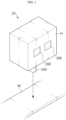
- FIG. 1 is a view showing a welding device 10 according to an embodiment of the present disclosure
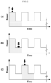
- FIG. 2 is a view showing a change in laser output by the welding device 10 of FIG. 1
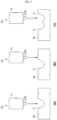
- FIG. 3 is a view showing the generation of a keyhole in a welding portion according to a change in laser output in FIG. 2 .
- the welding device 10 may be configured to perform welding at the welding portion W by irradiating a laser.
- the welding portion W may mean a coupling portion between components of a battery module (not shown).
- the battery module may include at least one secondary battery therein.
- welding between components of the battery module may be performed by a known keyhole welding method. More specifically, the welding device 10 may perform welding between a module case (not shown) and an end plate (not shown) of a battery module for accommodating a secondary battery therein, but is not limited thereto.
- the module case and the end plate may include an aluminum material. That is, the welding portion W may include an aluminum material. However, the welding portion W is not limited to aluminum and may also include aluminum and an alloy thereof.
- the welding device 10 may include a laser irradiation unit 100 and a laser power control unit 200. A portion of this laser irradiation unit 100 may be accommodated in the housing H. In addition, the laser power control unit 200 may be provided on the outer surface of the housing H.
- the laser irradiation unit 100 may be configured in the form of an optical system to irradiate a laser. Although not shown in detail, the laser may be irradiated in the form of a beam to the welding portion W.
- the laser irradiation unit 100 may include a laser light source (not shown) and a focusing lens (not shown).
- the laser light source may generate the laser.
- the focusing lens may improve the energy density of the laser generated from the laser light source.
- the laser may pass through the focusing lens and be irradiated to the welding portion W.
- the laser power control unit 200 may control the laser irradiation unit 100 to irradiate a laser with peak power and a laser with base power to the welding portion W, as shown in FIG. 2 .
- the base power may be a power having a lower magnitude than the peak power. That is, the laser power control unit 200 may control the laser irradiation unit 100 to irradiate different magnitudes of power to the same welding portion W.
- the laser power control unit 200 may include a processor.
- the laser irradiation unit 100 may irradiate a laser with peak power and a laser with base power so that two or more keyholes K may be formed by overlapping for one welding line in the welding portion W under the control of the laser power control unit 200.
- the keyhole K utilizes multiple reflection and absorption of energy in the focal section of the laser beam and may be formed approximately in the shape of a key hole.
- the housing H may be moved by a separate moving stage (not shown) so that the laser irradiation unit 100 may irradiate the laser to the welding portion W while moving for one welding line.
- the housing H accommodating the laser irradiation unit 100 may be moved to another welding line on the welding portion W. Thereafter, the laser irradiation unit 100 may repeatedly perform the above-described operation for another welding line on the welding portion W under the control of the laser power control unit 200.
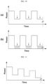
- the displayed area in the graph of FIG. 4 (a) means the heat input energy accumulated in the welding portion according to the laser irradiation time.
- the welding metal (the portion of the metal that melted and solidified during welding as a portion of the welding portion) in the welding portion may be excessively penetrated, thereby causing a meltdown phenomenon where the welding metal falls locally.
- the laser irradiation unit 100 irradiates a laser with peak power and a laser with base power to the welding portion W. Therefore, compared to the conventional CW laser welding method, the accumulation of heat input energy in the welding portion W according to the laser irradiation time may be achieved relatively slowly.
- This laser welding method by the welding device 10 of the present disclosure is a laser irradiation method in the form of combining the CW laser welding method and the pulse wave (PW) laser welding method, and can be referred to as a quasi-pulse laser welding method.
- the welding method according to the welding device 10 of the present disclosure includes the step of irradiating a laser with peak power to the welding portion W and the step of irradiating a laser with base power to the welding portion W.
- a laser with base power having a relatively lower output than a laser with peak power may be irradiated to the welding portion W between the sections where the laser with peak power is irradiated to the welding portion W. Therefore, in the case of the welding device 10 of the present disclosure, welding defects may be minimized by preventing excessive accumulation of heat input energy in the welding portion W.
- FIG. 5 is a view showing a change in laser output according to oscillation of a conventional pulse laser
- FIG. 6 is a view showing the laser absorption rate of pure aluminum according to temperature change.
- a pulse laser is irradiated to the welding portion in a periodically turned on/off manner.
- the welding portion is melted by irradiation of the pulse laser and changes from a solid state to a liquid state. At this time, it can be said that a keyhole is generated in the welding portion.
- the absorption rate of the laser in a solid state of the welding portion may be at least 3.8 times lower than that in a liquid state of the welding portion based on the melting point of pure aluminum.
- the welding portion that has changed to a solid state in the section of FIG. 5 (b) may need to be melted again. Therefore, the laser absorption rate of the welding portion in the solid state is relatively lower than the laser absorption rate of the welding portion in the liquid state, and thus the melting efficiency is lowered. As a result, there is a problem of slowing down the welding speed.
- the laser power control unit 200 provided in the welding device 10 of the present disclosure may be configured to control the laser irradiation unit 100 so that the welding portion W remains in a liquid state.
- the laser power control unit 200 may control the laser irradiation unit 100 to sequentially irradiate the laser with peak power and the laser with the base power to the welding portion W, so as to induce the welding portion W to remain in a liquid state without changing from the liquid state to the solid state.
- the welding device 10 of the present disclosure unlike the conventional PW laser welding method, it is possible to prevent the occurrence of a section in which the laser oscillation is completely turned off.
- the laser irradiation unit 100 may irradiate a laser with peak power to the welding portion W. Accordingly, the welding portion W may melt and change from a solid state to a liquid state. At this time, a keyhole K may be generated in the welding portion W, as shown in FIG. 3 (a) .
- the laser irradiation unit 100 may irradiate a laser with base power to the welding portion W. In this way, by irradiating a laser with base power having a relatively lower output than a laser with peak power to the welding portion W, it is possible to suppress the change of the welding portion W from the liquid state to the solid state again.
- the laser irradiation unit 100 may irradiate a laser with peak power to the welding portion W again.
- the liquid state of the welding portion W is maintained by the irradiation of the laser with base power in of FIG. 2 (b) , and thus, when irradiating the laser with peak power as shown in FIG. 2 (c) , a keyhole K may be generated in the welding portion W more easily.
- a keyhole K may be formed in the welding portion W by overlapping at least a portion of the keyhole K generated in FIG. 3 (a) .
- the laser absorption rate of the welding portion W may be increased by keeping the welding portion W in a liquid state during the welding process, thereby maintaining the same welding speed and welding productivity as in the prior art.
- the laser power control unit 200 may control the laser irradiation unit 100 to alternately irradiate a laser with peak power and a laser with base power to the welding portion W.
- the laser irradiation unit 100 may alternately and continuously irradiate a laser with peak power and a laser with base power to the welding portion W under the control of the laser power control unit 200.
- FIG. 7 is a view showing a simulation result for the boundary values of heat conduction welding and keyhole welding.
- a laser with peak power may have an output capable of forming a keyhole K in the welding portion W.
- a laser with base power may have an output that does not cause penetration in the welding portion W. That is, the laser with base power may have an output that hardly forms a penetration depth in the welding portion W, as shown in FIG. 7 . Therefore, since the laser with base power may have an output that hardly forms a penetration depth in the welding portion W as shown in FIG. 7 , it can be said to have an output that does not form penetration in the welding portion W. Meanwhile, when the output of the laser irradiated from the laser irradiation unit 100 is less than the output value at which the keyhole K is formed, the welding portion W may be welded in the form of heat conduction welding.
- the peak power in the welding device 10 of the present disclosure may be set to 2.2 kW/mm 2 or more. In the case of the above peak power value, it may be the minimum value at which the keyhole K may be formed in the welding portion W including an aluminum material.
- the base power in the welding device 10 of the present disclosure may be set within a range of approximately 0.92 kW/mm 2 to 1.42 kW/mm 2 .
- the welding device 10 of the present disclosure in the section where a laser with base power is irradiated to the welding portion W, it is possible to keep the welding portion W in a liquid state using only a laser with base power of low power that does not form penetration of the welding portion W.
- a laser with base power e.g., output range of 0.92 kW/mm 2 to 1.42 kW/mm 2
- the penetration depth in the keyhole K formed in the laser irradiation section of FIG. 3 (c) may be approximately the same as the penetration depth in the keyhole K formed in the laser irradiation section of FIG. 3 (a) .
- this embodiment by alternately irradiating a laser with peak power and a laser with base power to the welding portion W, it is possible to prevent excessive penetration in a specific area of the welding portion W by keeping penetration from being formed in the welding portion W in the section where the laser with base power is irradiated to the welding portion W while achieving the same welding speed as compared to the prior art. Accordingly, welding defects caused by meltdown may be minimized.
- the laser with base power may have an output capable of allowing the welding portion W to remain in a liquid state.
- the laser with base power may have a minimum output capable of allowing the welding portion W to remain in a liquid state during the process of alternately irradiating the laser with peak power and the laser with base power to the welding portion W.
- FIG. 8 is a view exemplarily showing a change in the pulse width of a laser by control of a laser power control unit 200 provided in the welding device 10 of FIG. 1 .
- FIG. 8 (a) shows a state before the pulse width of the laser with base power is adjusted
- FIG. 8 (b) shows a state after the pulse width of the laser with base power is adjusted.
- the laser power control unit 200 of the welding device 10 of the present disclosure may be configured to control the pulse width of the laser with base power.
- the welding portion W when the welding portion W includes a material (e.g., a metal material having a lower melting point than aluminum, and the like) that reacts more sensitively to the laser, penetration may occur in the welding portion W in the section where the laser with base power in the illustrated output range (an output range of 0.92 kW/mm 2 to 1.42 kW/mm 2 ) is irradiated to the welding portion W.
- a material e.g., a metal material having a lower melting point than aluminum, and the like
- penetration may occur in the welding portion W in the section where the laser with base power in the illustrated output range (an output range of 0.92 kW/mm 2 to 1.42 kW/mm 2 ) is irradiated to the welding portion W.
- the laser power control unit 200 may prevent penetration from being formed in the welding portion W in the section where the laser with base power is irradiated to the welding portion W by adjusting the pulse width of the laser with base power according to the characteristics of the welding portion W.
- the laser power control unit 200 may adjust the pulse width of the laser with base power to be smaller, as shown in the portion indicated by arrows and shades in FIG. 8 (b) .
- FIG. 9 is a view exemplarily showing a change in the pulse frequency of a laser by control of a laser power control unit 200 provided in the welding device 10 of FIG. 1 .
- FIG. 9 (a) shows a state before the pulse frequency of the laser with base power is adjusted
- FIG. 9 (b) shows a state after the pulse frequency of the laser with base power is adjusted.
- the laser power control unit 200 may be configured to control the pulse frequency of the laser with base power.
- the laser irradiation unit 100 may irradiate the laser with peak power and the laser with base power so that two or more keyholes K may be formed by overlapping each other for one welding line in the welding portion W under the control of the laser power control unit 200, as shown in FIG. 3 .
- the overlap area between at least two keyholes K in the welding portion W may be changed.
- the laser irradiation unit 100 alternately irradiates the laser with peak power and the laser with base power to the welding portion W, and thus, when the pulse frequency of the laser with base power is adjusted, the pulse frequency of the laser with peak power may also be adjusted.
- the laser power control unit 200 may adjust the pulse frequency of the laser with base power to increase, as shown in FIG. 9 (b) .
- the pulse frequency of the laser with peak power may also be adjusted to increase.
- the overlap area of the keyhole K in the welding portion W may be increased, and thus welding in the welding portion W may be made more stably.
- the welding area in the welding portion W is small, excessive accumulation of heat input energy in the welding portion W may be minimized while increasing the pulse frequency of the laser with base power to increase the welding speed.
- FIG. 10 is a view exemplarily showing a change in laser output by control of a laser power control unit 200 provided in the welding device 10 of FIG. 1 .
- FIG. 10 (a) shows a state before the output of the laser with base power is adjusted
- FIG. 10 (b) shows a state after the output of the laser with base power is adjusted.
- the laser power control unit 200 may be configured to control the output of the laser with base power.
- the welding portion W when the welding portion W includes a material (e.g., a metal material having a lower melting point than aluminum, and the like) that reacts more sensitively to the laser, penetration may occur in the welding portion W in the section where the laser with base power in the illustrated output range (an output range of 0.92 kW/mm 2 to 1.42 kW/mm 2 ) is irradiated to the welding portion W.
- a material e.g., a metal material having a lower melting point than aluminum, and the like
- penetration may occur in the welding portion W in the section where the laser with base power in the illustrated output range (an output range of 0.92 kW/mm 2 to 1.42 kW/mm 2 ) is irradiated to the welding portion W.
- the laser power control unit 200 may prevent penetration from being formed in the welding portion W in the section where the laser with base power is irradiated to the welding portion W by adjusting the output of the laser with base power according to the characteristics of the welding portion W.
- the laser power control unit 200 may adjust the output of the laser with base power to be smaller, as shown in the portion indicated by arrows and shades in FIG. 10 (b) .
- the welding device 10 of the present disclosure may further include an inspection unit 300.
- the inspection unit 300 may be configured to inspect a welding condition of the welding portion W after completion of welding by the welding device 10.
- the inspection unit 300 may include a processor, a camera (e.g., an infrared camera), an X-ray transmission device, and the like.
- the inspection unit 300 may be provided on the outer surface of the housing H described above.
- the inspection unit 300 may transmit such welding condition inspection information to the laser power control unit 200.
- the laser power control unit 200 may be configured to control the output of the laser with base power according to the welding condition inspection information provided from the inspection unit 300. That is, the laser power control unit 200 may control the output of the laser with base power so that welding defects or the like do not occur during the next step of welding by the welding device 10.
- the laser power control unit 200 may also be configured to control the pulse width or pulse frequency of the laser with base power according to the welding condition inspection information provided from the inspection unit 300.
- the inspection unit 300 may be configured to inspect a welding condition at the welding portion W during welding by the welding device 10.
- the inspection unit 300 may transmit such welding condition inspection information to the laser power control unit 200.
- the laser power control unit 200 may be configured to control the output of the laser with base power according to the welding condition inspection information provided from the inspection unit 300. That is, the laser power control unit 200 may control the output of the laser with base power so that no further welding defects or the like occur during welding by the welding device 10.
- the laser power control unit 200 may also be configured to control the pulse width or pulse frequency of the laser with base power according to the welding condition inspection information provided from the inspection unit 300.
- FIGS. 11 and 12 are views showing another control method of a laser by the welding device 10 of the present disclosure.
- the laser with base power is irradiated to the welding portion W between sections in which the laser with peak power is irradiated to the welding portion W, so that the liquid state of the welding portion W may be maintained throughout the entire welding process.
- the laser power control unit 200 may also control the irradiation of the laser by the laser irradiation unit 100 so that the output of the laser with peak power and the laser with base power is reduced over time, as shown in FIG. 11 .
- the laser power control unit 200 may also control the irradiation of the laser by the laser irradiation unit 100 so that the pulse width of the laser with peak power and the laser with base power is reduced over time, as shown in FIG. 12 .
- the liquid state of the welding portion W may be maintained by the irradiation of the laser with base power to the welding portion W. Therefore, welding defects may be minimized while injecting less energy into the welding portion W than in the prior art.
- welding was performed on the welding portion W using a welding device (model name: laser (Trumpf TruDiode 4006), optical system (Trumpf BEO D70 0° K200 F200 T950)).
- the welding portion W was made of pure aluminum, and the top/bottom of the extruded mono-frame AL6063 had a thickness of 2.0 mm, and the side had a thickness of 3.2 mm.
- the endplate ADC12 manufactured by die-cast was processed to correspond to the thickness of each side of the monoframe.
- the total length of the welding portion W was set to 562 mm on one side and 1124 mm on both sides.
- the overall width of the welding portion W was set to a bead width of 2.0 to 4.0 mm.
- the length of one welding line was set to 80 mm on the top, 96 mm on the side, and 210 mm on the bottom.
- the welding portion W was a coupling portion between the components of a battery module (not shown). Specifically, the welding portion W was a coupling portion between a module case (not shown) and an end plate (not shown).
- the welding device was set to irradiate a laser with peak power and a laser with base power to the welding portion W alternately and continuously.
- the output of the laser with peak power was set to 3300 W ⁇ 200 W in the section with a thickness of 2.0 mm on the top/bottom, and 3600 W ⁇ 200 W in the section with a thickness of 3.2 mm on the side.
- the output of the laser with base power was set to 1200 W ⁇ 200 W in the section with a thickness of 2.0 mm on the top/bottom, and 2000 W ⁇ 200 W in the section with a thickness of 3.2 mm on the side.
- the number of welding in one welding line was once, the welding speed for one welding line was 60 mm/sec, the total welding length was 1124 mm, and the total welding time was 18.7 seconds.
- the number of welding for one welding portion W including at least one welding line was once, and the total welding time for one welding portion W was 1.33 seconds in the 80 mm section on the top, 1.6 seconds in the 96 mm section on the side, and 3.5 seconds in the 210 mm section on the bottom.
- the irradiation time of the laser with peak power and the irradiation time of the laser with base power were set at the same ratio.
- the welding device was set to alternately irradiate a laser with peak power and a laser with base power so that two or more keyholes K may be formed by overlapping with each other for one welding line.
- welding was performed in the above-described manner to form a welding portion W, and welding quality was measured for the formed welding portion W. More specifically, a plurality of samples were produced in the above-described manner for each week over a period of 10 weeks, and the number of samples in which welding defects occurred for the welding portion W of the produced samples was counted, whereby the counted results are shown in Table 1. That is, Table 1 shows the number of battery modules, which were indicated as Examples 1 to 10 for each week and were produced for one week for each example, and the number of welding defects (e.g., meltdown) in the produced battery modules, that is, in the welding portion W included in each sample, as data tested over a total of 10 weeks.
- welding defects e.g., meltdown
- the welding portion was made of pure aluminum, and the top/bottom of the extruded mono-frame AL6063 had a thickness of 2.0 mm, and the side had a thickness of 3.2 mm.
- the endplate ADC12 manufactured by die-cast was processed to correspond to the thickness of each side of the monoframe.
- the total length of the welding portion was set to 562 mm on one side and 1124 mm on both sides.
- the overall width of the welding portion was set to a bead width of 2.0 to 4.0 mm.
- the length of one welding line was set to 80 mm on the top, 96 mm on the side, and 210 mm on the bottom.
- the welding portion was a coupling portion between the components of a battery module (not shown). Specifically, the welding portion was a coupling portion between a module case (not shown) and an end plate (not shown).
- the output of the laser with peak power was set to 3300 W ⁇ 200 W in the section with a thickness of 2.0 mm on the top/bottom, and 3600 W ⁇ 200 W in the section with a thickness of 3.2 mm on the side.
- the number of welding in one welding line was once, the welding speed for one welding line was 10 mm/sec, the total welding length was 1124 mm, and the total welding time was 112.4 seconds.
- the number of welding for one welding portion including at least one welding line was once, and the total welding time for one welding portion was 8 seconds in the 80 mm section on the top, 9.6 seconds in the 96 mm section on the side, and 21 seconds in the 210 mm section on the bottom.
- Example 1 Battery module production volume per week (units) Number of welding defects in welding portion (times) Example 1 2,560 1 Example 2 15,285 6 Example 3 16,987 7 Example 4 20,200 0 Example 5 20,416 7 Example 6 21,421 8 Example 7 30,562 9 Example 8 28,093 6 Example 9 34,220 9 Example 10 23,889 3 Comparative Example 10,040 27
- Example 1 2,560 battery modules were produced in one week, in which case, the number of welding defects in the welding portion W was once. In this case, the occurrence rate of welding defects is only about 0.04%.
- Example 2 15,285 battery modules were produced in one week, in which case, the number of welding defects in the welding portion W was 6 times. In this case, the occurrence rate of welding defects is only about 0.04%.
- Example 3 16,987 battery modules were produced in one week, in which case, the number of welding defects in the welding portion W was 7 times. In this case, the occurrence rate of welding defects is only about 0.04%.
- Example 4 20,200 battery modules were produced in one week, in which case, the number of welding defects in the welding portion W was zero.
- Example 5 20,416 battery modules were produced in one week, in which case, the number of welding defects in the welding portion W was 7 times. In this case, the occurrence rate of welding defects is only about 0.03%.
- Example 6 21,421 battery modules were produced in one week, in which case, the number of welding defects in the welding portion W was 8 times. In this case, the occurrence rate of welding defects is only about 0.04%.
- Example 7 30,562 battery modules were produced in one week, in which case, the number of welding defects in the welding portion W was 9 times. In this case, the occurrence rate of welding defects is only about 0.03%.
- Example 8 28093 battery modules were produced in one week, in which case, the number of welding defects in the welding portion W was 6 times. In this case, the occurrence rate of welding defects is only about 0.02%.
- Example 9 34,220 battery modules were produced in one week, in which case, the number of welding defects in the welding portion W was 9 times. In this case, the occurrence rate of welding defects is only about 0.03%.
- Example 10 23889 battery modules were produced in one week, in which case, the number of welding defects in the welding portion W was 3 times. In this case, the occurrence rate of welding defects is only about 0.01%.
- Example 2 In addition, in the case of the Comparative Example, it was found that more welding defects occurred than in Example 2, which produced about 5,000 more products than the number of products produced in the Comparative Example.
- welding defects in the welding portion W may be minimized compared to the conventional laser welding method.
- the battery manufacturing device according to the present disclosure may include the welding device 10 described above. Also, the battery manufacturing device according to the present disclosure may further include various devices (e.g., a battery module inspection device) known in the art for manufacturing battery modules in addition to the welding device 10 described above.
- various devices e.g., a battery module inspection device
- the vehicle manufacturing device according to the present disclosure may include the welding device 10 described above. Also, the vehicle manufacturing device according to the present disclosure may further include various devices (e.g., a vehicle inspection device) known in the art for manufacturing vehicles in addition to the welding device 10 described above.
- various devices e.g., a vehicle inspection device
Landscapes
- Physics & Mathematics (AREA)
- Optics & Photonics (AREA)
- Engineering & Computer Science (AREA)
- Plasma & Fusion (AREA)
- Mechanical Engineering (AREA)
- Chemical & Material Sciences (AREA)
- Chemical Kinetics & Catalysis (AREA)
- Electrochemistry (AREA)
- General Chemical & Material Sciences (AREA)
- Laser Beam Processing (AREA)
- Battery Mounting, Suspending (AREA)
Abstract
Description
- The present disclosure relates to a welding device, a welding method, a battery manufacturing device and a vehicle manufacturing device, and more specifically, to a welding device and a welding method that may improve welding efficiency, and a battery manufacturing device and a vehicle manufacturing device including such a welding device.
- The present application claims priority to
Korean Patent Application No. 10-2022-0084677 filed on July 8, 2022 Korean Patent Application No. 10-2022-0136866 filed on October 21, 2022 - In general, a welding device includes a laser light source and optical components such as a focusing lens for increasing the energy density of the laser irradiated from the laser light source.
- This welding device may be used, for example, for coupling components constituting a battery module. As an example, a battery module may be configured to create a dense structure by overlapping or stacking a plurality of battery cells (e.g., secondary batteries) in a state of being mounted on themselves or in a cartridge to provide high voltage and high current, and then electrically connect them.
- In order to configure a battery module with a stable structure in such a battery module, it is important to perform good welding between a module case in which battery cells are accommodated and an end plate configured to cover a bus bar electrically connecting the battery cells. As an example, a welding device for keyhole welding of a welding portion (e.g., between the module case and the end plate) may be configured.
- Meanwhile, in the case of conventional welding devices, welding between the module case and the end plate is performed by a continuous wave (CW) laser welding method. In the case of this CW laser welding method, the accumulation of heat input energy in the welding portion may increase according to the welding time. In this case, there is a problem that welding defects occur in the welding portion due to excessive accumulation of heat input energy in the welding portion.
- The present disclosure is designed to solve the problems of the related art, and therefore the present disclosure is directed to providing a welding device and a welding method that may improve welding efficiency, and a battery manufacturing device and a vehicle manufacturing device including such a welding device.
- However, technical problems to be solved by the present disclosure are not limited to the above-described problems, and other problems not mentioned herein may be clearly understood by those skilled in the art from the following description of the present disclosure.
- A welding device according to one aspect of the present disclosure includes a laser irradiation unit configured to irradiate a laser; and a laser power control unit configured to control the laser irradiation unit to irradiate a laser with peak power and a laser with base power to a welding portion.
- Preferably, the laser power control unit may be configured to control the laser irradiation unit so that the welding portion remains in a liquid state.
- Preferably, the laser power control unit may be configured to control the laser irradiation unit to alternately irradiate the laser with peak power and the laser with base power to the welding portion.
- Preferably, the laser with peak power may have an output capable of forming a keyhole in the welding portion, and the laser with base power may have an output with which penetration is not formed in the welding portion.
- Preferably, the laser with base power may have an output capable of allowing the welding portion to remain in a liquid state.
- Preferably, the laser power control unit may be configured to control the pulse width of the laser with base power.
- Preferably, the laser power control unit may be configured to control the pulse frequency of the laser with base power.
- Preferably, the laser power control unit may be configured to control the output of the laser with base power.
- Preferably, the welding device may further include an inspection unit configured to inspect a welding condition in the welding portion after completion of welding by the welding device, wherein the laser power control unit may be configured to control the output of the laser with base power according to the welding condition inspection information provided from the inspection unit.
- Preferably, the welding device may further include an inspection unit configured to inspect a welding condition in the welding portion during welding by the welding device, wherein the laser power control unit may be configured to control the output of the laser with base power according to the welding condition inspection information provided from the inspection unit.
- A welding method according to one aspect of the present disclosure includes a step of irradiating a laser with peak power to a welding portion; and a step of irradiating a laser with base power to the welding portion.
- A battery manufacturing device according to one aspect of the present disclosure may include a welding device according to one aspect of the present disclosure as described above.
- A vehicle manufacturing device according to one aspect of the present disclosure may include a welding device according to one aspect of the present disclosure as described above.
- According to an embodiment of the present disclosure, while minimizing welding defects by preventing excessive accumulation of heat input energy in the welding portion compared to the prior art, the laser absorption rate of the welding portion may be increased by keeping the welding portion in a liquid state during the welding process, thereby maintaining the same welding speed and welding productivity as in the prior art.
- In addition, several other additional effects may be achieved by various embodiments of the present disclosure. These various effects of the present disclosure will be described in detail in each embodiment, or descriptions of effects that may be easily understood by those skilled in the art will be omitted.
- The accompanying drawings illustrate a preferred embodiment of the present disclosure and together with the foregoing disclosure, serve to provide further understanding of the technical features of the present disclosure, and thus the present disclosure is not construed as being limited to the drawing.
-
FIG. 1 is a view showing a welding device according to an embodiment of the present disclosure. -
FIG. 2 is a view showing a change in laser output by the welding device ofFIG. 1 . -
FIG. 3 is a view showing the generation of a keyhole in a welding portion according to a change in laser output inFIG. 2 . -
FIG. 4 is a view showing a difference in the amount of energy accumulated in the welding portion according to the laser oscillation mode. -
FIG. 5 is a view showing a change in laser output according to oscillation of a conventional pulse laser. -
FIG. 6 is a view showing the laser absorption rate of pure aluminum according to temperature change. -
FIG. 7 is a view showing a simulation result for the boundary values of heat conduction welding and keyhole welding. -
FIG. 8 is a view exemplarily showing a change in the pulse width of a laser by control of a laser power control unit provided in the welding device ofFIG. 1 . -
FIG. 9 is a view exemplarily showing a change in the pulse frequency of a laser by control of a laser power control unit provided in the welding device ofFIG. 1 . -
FIG. 10 is a view exemplarily showing a change in laser output by control of a laser power control unit provided in the welding device ofFIG. 1 . -
FIGS. 11 and12 are views showing another control method of a laser by the welding device of the present disclosure. - Hereinafter, preferred embodiments of the present disclosure will be described in detail with reference to the accompanying drawings. Prior to the description, it should be understood that the terms used in the specification and the appended claims should not be construed as limited to general and dictionary meanings, but interpreted based on the meanings and concepts corresponding to technical aspects of the present disclosure on the basis of the principle that the inventor is allowed to define terms appropriately for the best explanation.
-
FIG. 1 is a view showing awelding device 10 according to an embodiment of the present disclosure,FIG. 2 is a view showing a change in laser output by thewelding device 10 ofFIG. 1 , andFIG. 3 is a view showing the generation of a keyhole in a welding portion according to a change in laser output inFIG. 2 . - Referring to
FIGS. 1 to 3 , thewelding device 10 according to an embodiment of the present disclosure may be configured to perform welding at the welding portion W by irradiating a laser. - As an example, the welding portion W may mean a coupling portion between components of a battery module (not shown). In this case, the battery module may include at least one secondary battery therein.
- Illustratively, welding between components of the battery module may be performed by a known keyhole welding method. More specifically, the
welding device 10 may perform welding between a module case (not shown) and an end plate (not shown) of a battery module for accommodating a secondary battery therein, but is not limited thereto. - Illustratively, the module case and the end plate may include an aluminum material. That is, the welding portion W may include an aluminum material. However, the welding portion W is not limited to aluminum and may also include aluminum and an alloy thereof.
- As shown in
FIG. 1 , thewelding device 10 may include alaser irradiation unit 100 and a laserpower control unit 200. A portion of thislaser irradiation unit 100 may be accommodated in the housing H. In addition, the laserpower control unit 200 may be provided on the outer surface of the housing H. - The
laser irradiation unit 100 may be configured in the form of an optical system to irradiate a laser. Although not shown in detail, the laser may be irradiated in the form of a beam to the welding portion W. - In an embodiment, the
laser irradiation unit 100 may include a laser light source (not shown) and a focusing lens (not shown). - The laser light source may generate the laser.
- The focusing lens may improve the energy density of the laser generated from the laser light source. In this case, the laser may pass through the focusing lens and be irradiated to the welding portion W.
- The laser
power control unit 200 may control thelaser irradiation unit 100 to irradiate a laser with peak power and a laser with base power to the welding portion W, as shown inFIG. 2 . Here, the base power may be a power having a lower magnitude than the peak power. That is, the laserpower control unit 200 may control thelaser irradiation unit 100 to irradiate different magnitudes of power to the same welding portion W. As an example, the laserpower control unit 200 may include a processor. - In addition, as shown in
FIG. 3 , thelaser irradiation unit 100 may irradiate a laser with peak power and a laser with base power so that two or more keyholes K may be formed by overlapping for one welding line in the welding portion W under the control of the laserpower control unit 200. Here, the keyhole K utilizes multiple reflection and absorption of energy in the focal section of the laser beam and may be formed approximately in the shape of a key hole. In this case, the housing H may be moved by a separate moving stage (not shown) so that thelaser irradiation unit 100 may irradiate the laser to the welding portion W while moving for one welding line. - Also, after welding is completed for one welding line, the housing H accommodating the
laser irradiation unit 100 may be moved to another welding line on the welding portion W. Thereafter, thelaser irradiation unit 100 may repeatedly perform the above-described operation for another welding line on the welding portion W under the control of the laserpower control unit 200. - As shown in
FIG. 4 (a) , in the case of a conventional continuous wave (CW) laser welding method, excessive energy is accumulated in the welding portion as the laser irradiation time to the welding portion increases. At this time, the displayed area in the graph ofFIG. 4 (a) means the heat input energy accumulated in the welding portion according to the laser irradiation time. - In this case, the welding metal (the portion of the metal that melted and solidified during welding as a portion of the welding portion) in the welding portion may be excessively penetrated, thereby causing a meltdown phenomenon where the welding metal falls locally.
- Meanwhile, referring to
FIG. 4 (b) , in the case of the laser welding method by thewelding device 10 of the present disclosure, it can be said that thelaser irradiation unit 100 irradiates a laser with peak power and a laser with base power to the welding portion W. Therefore, compared to the conventional CW laser welding method, the accumulation of heat input energy in the welding portion W according to the laser irradiation time may be achieved relatively slowly. This laser welding method by thewelding device 10 of the present disclosure is a laser irradiation method in the form of combining the CW laser welding method and the pulse wave (PW) laser welding method, and can be referred to as a quasi-pulse laser welding method. - That is, the welding method according to the
welding device 10 of the present disclosure includes the step of irradiating a laser with peak power to the welding portion W and the step of irradiating a laser with base power to the welding portion W. - When the laser is irradiated to the welding portion W in this quasi-pulse mode, a laser with base power having a relatively lower output than a laser with peak power may be irradiated to the welding portion W between the sections where the laser with peak power is irradiated to the welding portion W. Therefore, in the case of the
welding device 10 of the present disclosure, welding defects may be minimized by preventing excessive accumulation of heat input energy in the welding portion W. -
FIG. 5 is a view showing a change in laser output according to oscillation of a conventional pulse laser, andFIG. 6 is a view showing the laser absorption rate of pure aluminum according to temperature change. - Referring to
FIG. 5 , in the case of the conventional PW laser welding method, a pulse laser is irradiated to the welding portion in a periodically turned on/off manner. - As indicated by an arrow in
FIG. 5 (a) in the PW laser welding method, in the section where the oscillation of the pulse laser is on, the welding portion is melted by irradiation of the pulse laser and changes from a solid state to a liquid state. At this time, it can be said that a keyhole is generated in the welding portion. - On the other hand, as indicated by an arrow in
FIG. 5 (b) , in the section where the oscillation of the pulse laser is off, there is no energy input to the welding portion, so it can be said that the welding portion changes from a liquid state to a solid state again. - Referring to
FIG. 6 , when a pulse laser is oscillated at a certain wavelength (e.g., 1.06 µm) for pure aluminum, the absorption rate of the laser in a solid state of the welding portion may be at least 3.8 times lower than that in a liquid state of the welding portion based on the melting point of pure aluminum. - Accordingly, as indicated by an arrow in
FIG. 5 (c) , in the section where the oscillation of the pulse laser is turned on again, the welding portion that has changed to a solid state in the section ofFIG. 5 (b) may need to be melted again. Therefore, the laser absorption rate of the welding portion in the solid state is relatively lower than the laser absorption rate of the welding portion in the liquid state, and thus the melting efficiency is lowered. As a result, there is a problem of slowing down the welding speed. - On the other hand, the laser
power control unit 200 provided in thewelding device 10 of the present disclosure may be configured to control thelaser irradiation unit 100 so that the welding portion W remains in a liquid state. - That is, in the
welding device 10 of the present disclosure, the laserpower control unit 200 may control thelaser irradiation unit 100 to sequentially irradiate the laser with peak power and the laser with the base power to the welding portion W, so as to induce the welding portion W to remain in a liquid state without changing from the liquid state to the solid state. To this end, in the case of thewelding device 10 of the present disclosure, unlike the conventional PW laser welding method, it is possible to prevent the occurrence of a section in which the laser oscillation is completely turned off. - Specifically, referring to the portion indicated by an arrow in
FIG. 2 (a) , under the control of the laserpower control unit 200, thelaser irradiation unit 100 may irradiate a laser with peak power to the welding portion W. Accordingly, the welding portion W may melt and change from a solid state to a liquid state. At this time, a keyhole K may be generated in the welding portion W, as shown inFIG. 3 (a) . - In addition, referring to the portion indicated by an arrow in
FIG. 2 (b) , under the control of the laserpower control unit 200, thelaser irradiation unit 100 may irradiate a laser with base power to the welding portion W. In this way, by irradiating a laser with base power having a relatively lower output than a laser with peak power to the welding portion W, it is possible to suppress the change of the welding portion W from the liquid state to the solid state again. - In this case, additional penetration may not occur in the welding portion W, as shown in
FIG. 3 (b) . This will be described in more detail in the related description below. - In addition, referring to the portion indicated by an arrow in
FIG. 2 (c) , under the control of the laserpower control unit 200, thelaser irradiation unit 100 may irradiate a laser with peak power to the welding portion W again. At this time, the liquid state of the welding portion W is maintained by the irradiation of the laser with base power in ofFIG. 2 (b) , and thus, when irradiating the laser with peak power as shown inFIG. 2 (c) , a keyhole K may be generated in the welding portion W more easily. Meanwhile, as shown inFIG. 3 (c) , a keyhole K may be formed in the welding portion W by overlapping at least a portion of the keyhole K generated inFIG. 3 (a) . - According to this embodiment, while minimizing welding defects by preventing excessive accumulation of heat input energy in the welding portion W compared to the prior art, the laser absorption rate of the welding portion W may be increased by keeping the welding portion W in a liquid state during the welding process, thereby maintaining the same welding speed and welding productivity as in the prior art.
- Referring to
FIG. 2 again, the laserpower control unit 200 may control thelaser irradiation unit 100 to alternately irradiate a laser with peak power and a laser with base power to the welding portion W. - Specifically, the
laser irradiation unit 100 may alternately and continuously irradiate a laser with peak power and a laser with base power to the welding portion W under the control of the laserpower control unit 200. - Accordingly, while injecting less energy into the welding portion W than in the prior art, there may be no section in which laser irradiation is turned off, thereby allowing the welding portion W to remain in a liquid state during the welding process more reliably.
-
FIG. 7 is a view showing a simulation result for the boundary values of heat conduction welding and keyhole welding. - Referring to
FIG. 7 , in thewelding device 10 of the present disclosure, a laser with peak power may have an output capable of forming a keyhole K in the welding portion W. In addition, a laser with base power may have an output that does not cause penetration in the welding portion W. That is, the laser with base power may have an output that hardly forms a penetration depth in the welding portion W, as shown inFIG. 7 . Therefore, since the laser with base power may have an output that hardly forms a penetration depth in the welding portion W as shown inFIG. 7 , it can be said to have an output that does not form penetration in the welding portion W. Meanwhile, when the output of the laser irradiated from thelaser irradiation unit 100 is less than the output value at which the keyhole K is formed, the welding portion W may be welded in the form of heat conduction welding. - As an example, the peak power in the
welding device 10 of the present disclosure may be set to 2.2 kW/mm2 or more. In the case of the above peak power value, it may be the minimum value at which the keyhole K may be formed in the welding portion W including an aluminum material. In addition, the base power in thewelding device 10 of the present disclosure may be set within a range of approximately 0.92 kW/mm2 to 1.42 kW/mm2. - That is, in the
welding device 10 of the present disclosure, in the section where a laser with base power is irradiated to the welding portion W, it is possible to keep the welding portion W in a liquid state using only a laser with base power of low power that does not form penetration of the welding portion W. This can be seen inFIG. 7 that no penetration depth of the welding portion W occurs or the penetration depth of the welding portion W is very small when a laser with base power (e.g., output range of 0.92 kW/mm2 to 1.42 kW/mm2) is irradiated to the welding portion W. - Therefore, the penetration depth in the keyhole K formed in the laser irradiation section of
FIG. 3 (c) may be approximately the same as the penetration depth in the keyhole K formed in the laser irradiation section ofFIG. 3 (a) . - According to this embodiment, by alternately irradiating a laser with peak power and a laser with base power to the welding portion W, it is possible to prevent excessive penetration in a specific area of the welding portion W by keeping penetration from being formed in the welding portion W in the section where the laser with base power is irradiated to the welding portion W while achieving the same welding speed as compared to the prior art. Accordingly, welding defects caused by meltdown may be minimized.
- In particular, the laser with base power may have an output capable of allowing the welding portion W to remain in a liquid state.
- That is, the laser with base power may have a minimum output capable of allowing the welding portion W to remain in a liquid state during the process of alternately irradiating the laser with peak power and the laser with base power to the welding portion W.
-
FIG. 8 is a view exemplarily showing a change in the pulse width of a laser by control of a laserpower control unit 200 provided in thewelding device 10 ofFIG. 1 . In this case,FIG. 8 (a) shows a state before the pulse width of the laser with base power is adjusted, andFIG. 8 (b) shows a state after the pulse width of the laser with base power is adjusted. - Referring to
FIG. 8 , the laserpower control unit 200 of thewelding device 10 of the present disclosure may be configured to control the pulse width of the laser with base power. - In an embodiment of the present disclosure, when the welding portion W includes a material (e.g., a metal material having a lower melting point than aluminum, and the like) that reacts more sensitively to the laser, penetration may occur in the welding portion W in the section where the laser with base power in the illustrated output range (an output range of 0.92 kW/mm2 to 1.42 kW/mm2) is irradiated to the welding portion W.
- In this case, the laser
power control unit 200 may prevent penetration from being formed in the welding portion W in the section where the laser with base power is irradiated to the welding portion W by adjusting the pulse width of the laser with base power according to the characteristics of the welding portion W. Illustratively, when the welding portion W includes a material that reacts more sensitively to the laser, the laserpower control unit 200 may adjust the pulse width of the laser with base power to be smaller, as shown in the portion indicated by arrows and shades inFIG. 8 (b) . - According to this embodiment, excessive penetration in a specific area of the welding portion W may be prevented by controlling the pulse width of the laser with base power according to the characteristics of the welding portion W. Accordingly, welding defects caused by meltdown may be minimized.
-
FIG. 9 is a view exemplarily showing a change in the pulse frequency of a laser by control of a laserpower control unit 200 provided in thewelding device 10 ofFIG. 1 . In this case,FIG. 9 (a) shows a state before the pulse frequency of the laser with base power is adjusted, andFIG. 9 (b) shows a state after the pulse frequency of the laser with base power is adjusted. - Referring to
FIG. 9 , the laserpower control unit 200 may be configured to control the pulse frequency of the laser with base power. - As described above, the
laser irradiation unit 100 may irradiate the laser with peak power and the laser with base power so that two or more keyholes K may be formed by overlapping each other for one welding line in the welding portion W under the control of the laserpower control unit 200, as shown inFIG. 3 . - In the
welding device 10 of the present disclosure, when the pulse frequency of the laser with base power is adjusted, the overlap area between at least two keyholes K in the welding portion W may be changed. At this time, thelaser irradiation unit 100 alternately irradiates the laser with peak power and the laser with base power to the welding portion W, and thus, when the pulse frequency of the laser with base power is adjusted, the pulse frequency of the laser with peak power may also be adjusted. - Illustratively, the laser
power control unit 200 may adjust the pulse frequency of the laser with base power to increase, as shown inFIG. 9 (b) . At this time, the pulse frequency of the laser with peak power may also be adjusted to increase. - According to this embodiment, when the pulse frequency of the laser with base power is increased, the overlap area of the keyhole K in the welding portion W may be increased, and thus welding in the welding portion W may be made more stably. In addition, when the welding area in the welding portion W is small, excessive accumulation of heat input energy in the welding portion W may be minimized while increasing the pulse frequency of the laser with base power to increase the welding speed.
-
FIG. 10 is a view exemplarily showing a change in laser output by control of a laserpower control unit 200 provided in thewelding device 10 ofFIG. 1 . In this case,FIG. 10 (a) shows a state before the output of the laser with base power is adjusted, andFIG. 10 (b) shows a state after the output of the laser with base power is adjusted. - Referring to
FIG. 10 , the laserpower control unit 200 may be configured to control the output of the laser with base power. - In an embodiment of the present disclosure, when the welding portion W includes a material (e.g., a metal material having a lower melting point than aluminum, and the like) that reacts more sensitively to the laser, penetration may occur in the welding portion W in the section where the laser with base power in the illustrated output range (an output range of 0.92 kW/mm2 to 1.42 kW/mm2) is irradiated to the welding portion W.
- In this case, the laser
power control unit 200 may prevent penetration from being formed in the welding portion W in the section where the laser with base power is irradiated to the welding portion W by adjusting the output of the laser with base power according to the characteristics of the welding portion W. Illustratively, when the welding portion W includes a material that reacts more sensitively to the laser, the laserpower control unit 200 may adjust the output of the laser with base power to be smaller, as shown in the portion indicated by arrows and shades inFIG. 10 (b) . - According to this embodiment, excessive penetration in a specific area of the welding portion W may be prevented by controlling the output of the laser with base power according to the characteristics of the welding portion W. Accordingly, welding defects caused by meltdown may be minimized.
- Referring to
FIG. 1 , thewelding device 10 of the present disclosure may further include aninspection unit 300. - The
inspection unit 300 may be configured to inspect a welding condition of the welding portion W after completion of welding by thewelding device 10. As an example, theinspection unit 300 may include a processor, a camera (e.g., an infrared camera), an X-ray transmission device, and the like. Also, theinspection unit 300 may be provided on the outer surface of the housing H described above. - For example, when the
inspection unit 300 senses the occurrence of excessive penetration in a specific area of the welding portion W after completion of welding by thewelding device 10, theinspection unit 300 may transmit such welding condition inspection information to the laserpower control unit 200. - At this time, the laser
power control unit 200 may be configured to control the output of the laser with base power according to the welding condition inspection information provided from theinspection unit 300. That is, the laserpower control unit 200 may control the output of the laser with base power so that welding defects or the like do not occur during the next step of welding by thewelding device 10. - Meanwhile, the laser
power control unit 200 may also be configured to control the pulse width or pulse frequency of the laser with base power according to the welding condition inspection information provided from theinspection unit 300. - Meanwhile, the
inspection unit 300 may be configured to inspect a welding condition at the welding portion W during welding by thewelding device 10. - For example, when the
inspection unit 300 senses the occurrence of excessive penetration in a specific area of the welding portion W during welding by thewelding device 10, theinspection unit 300 may transmit such welding condition inspection information to the laserpower control unit 200. - At this time, the laser
power control unit 200 may be configured to control the output of the laser with base power according to the welding condition inspection information provided from theinspection unit 300. That is, the laserpower control unit 200 may control the output of the laser with base power so that no further welding defects or the like occur during welding by thewelding device 10. - Meanwhile, the laser
power control unit 200 may also be configured to control the pulse width or pulse frequency of the laser with base power according to the welding condition inspection information provided from theinspection unit 300. -
FIGS. 11 and12 are views showing another control method of a laser by thewelding device 10 of the present disclosure. - In the case of the present disclosure, the laser with base power is irradiated to the welding portion W between sections in which the laser with peak power is irradiated to the welding portion W, so that the liquid state of the welding portion W may be maintained throughout the entire welding process.
- At this time, in the case of the
welding device 10 of the present disclosure, the laserpower control unit 200 may also control the irradiation of the laser by thelaser irradiation unit 100 so that the output of the laser with peak power and the laser with base power is reduced over time, as shown inFIG. 11 . Alternatively, in the case of thewelding device 10 of the present disclosure, the laserpower control unit 200 may also control the irradiation of the laser by thelaser irradiation unit 100 so that the pulse width of the laser with peak power and the laser with base power is reduced over time, as shown inFIG. 12 . In addition, in the case of thewelding device 10 of the present disclosure, the laserpower control unit 200 may also control the irradiation of the laser by thelaser irradiation unit 100 so that both the output and the pulse width of the laser with peak power and the laser with base power are reduced over time. - In this way, in the case of the
welding device 10 of the present disclosure, even if the irradiation of the laser is controlled as shown inFIGS. 11 or12 , the liquid state of the welding portion W may be maintained by the irradiation of the laser with base power to the welding portion W. Therefore, welding defects may be minimized while injecting less energy into the welding portion W than in the prior art. - Hereinafter, in order to show the effect of the
welding device 10 of the present disclosure more specifically, it will be described in more detail with reference to examples and comparative examples. However, the embodiments according to the present disclosure may be modified into various other forms, and the scope of the present disclosure should not be construed as being limited to the embodiments described in detail below. - As shown in
FIG. 1 , welding was performed on the welding portion W using a welding device (model name: laser (Trumpf TruDiode 4006), optical system (Trumpf BEO D70 0° K200 F200 T950)). - At this time, in all examples, the welding portion W was made of pure aluminum, and the top/bottom of the extruded mono-frame AL6063 had a thickness of 2.0 mm, and the side had a thickness of 3.2 mm. In addition, the endplate ADC12 manufactured by die-cast was processed to correspond to the thickness of each side of the monoframe. Also, the total length of the welding portion W was set to 562 mm on one side and 1124 mm on both sides. And, the overall width of the welding portion W was set to a bead width of 2.0 to 4.0 mm. In addition, the length of one welding line was set to 80 mm on the top, 96 mm on the side, and 210 mm on the bottom. Also, the welding portion W was a coupling portion between the components of a battery module (not shown). Specifically, the welding portion W was a coupling portion between a module case (not shown) and an end plate (not shown).
- In addition, as shown in
FIG. 2 , the welding device was set to irradiate a laser with peak power and a laser with base power to the welding portion W alternately and continuously. At this time, the output of the laser with peak power was set to 3300 W ± 200 W in the section with a thickness of 2.0 mm on the top/bottom, and 3600 W ± 200 W in the section with a thickness of 3.2 mm on the side. The output of the laser with base power was set to 1200 W ± 200 W in the section with a thickness of 2.0 mm on the top/bottom, and 2000 W ± 200 W in the section with a thickness of 3.2 mm on the side. In addition, the number of welding in one welding line was once, the welding speed for one welding line was 60 mm/sec, the total welding length was 1124 mm, and the total welding time was 18.7 seconds. Also, the number of welding for one welding portion W including at least one welding line was once, and the total welding time for one welding portion W was 1.33 seconds in the 80 mm section on the top, 1.6 seconds in the 96 mm section on the side, and 3.5 seconds in the 210 mm section on the bottom. In addition, the irradiation time of the laser with peak power and the irradiation time of the laser with base power were set at the same ratio. - In addition, as shown in
FIG. 3 , the welding device was set to alternately irradiate a laser with peak power and a laser with base power so that two or more keyholes K may be formed by overlapping with each other for one welding line. - According to an embodiment of the present disclosure, welding was performed in the above-described manner to form a welding portion W, and welding quality was measured for the formed welding portion W. More specifically, a plurality of samples were produced in the above-described manner for each week over a period of 10 weeks, and the number of samples in which welding defects occurred for the welding portion W of the produced samples was counted, whereby the counted results are shown in Table 1. That is, Table 1 shows the number of battery modules, which were indicated as Examples 1 to 10 for each week and were produced for one week for each example, and the number of welding defects (e.g., meltdown) in the produced battery modules, that is, in the welding portion W included in each sample, as data tested over a total of 10 weeks.
- Meanwhile, in the case of the comparative example, welding was performed by irradiating only the laser with peak power to the welding portion using the conventional pulse wave (PW) laser welding method shown in
FIG. 5 . At this time, the welding portion was made of pure aluminum, and the top/bottom of the extruded mono-frame AL6063 had a thickness of 2.0 mm, and the side had a thickness of 3.2 mm. In addition, the endplate ADC12 manufactured by die-cast was processed to correspond to the thickness of each side of the monoframe. Also, the total length of the welding portion was set to 562 mm on one side and 1124 mm on both sides. And, the overall width of the welding portion was set to a bead width of 2.0 to 4.0 mm. In addition, the length of one welding line was set to 80 mm on the top, 96 mm on the side, and 210 mm on the bottom. Also, the welding portion was a coupling portion between the components of a battery module (not shown). Specifically, the welding portion was a coupling portion between a module case (not shown) and an end plate (not shown). - In addition, the output of the laser with peak power was set to 3300 W ± 200 W in the section with a thickness of 2.0 mm on the top/bottom, and 3600 W ± 200 W in the section with a thickness of 3.2 mm on the side. In addition, the number of welding in one welding line was once, the welding speed for one welding line was 10 mm/sec, the total welding length was 1124 mm, and the total welding time was 112.4 seconds. Also, the number of welding for one welding portion including at least one welding line was once, and the total welding time for one welding portion was 8 seconds in the 80 mm section on the top, 9.6 seconds in the 96 mm section on the side, and 21 seconds in the 210 mm section on the bottom. In addition, the irradiation time of the laser with peak power and the time in the section where the laser is not irradiated were set at the same ratio.
[Table 1] Battery module production volume per week (units) Number of welding defects in welding portion (times) Example 1 2,560 1 Example 2 15,285 6 Example 3 16,987 7 Example 4 20,200 0 Example 5 20,416 7 Example 6 21,421 8 Example 7 30,562 9 Example 8 28,093 6 Example 9 34,220 9 Example 10 23,889 3 Comparative Example 10,040 27 - Referring to the results in Table 1 above, it can be seen that the occurrence rate of welding defects was very low in Examples 1 to 10, whereas the occurrence rate of welding defects was significantly higher compared to Examples 1 to 10 in the case of Comparative Example.
- More specifically, in Example 1, 2,560 battery modules were produced in one week, in which case, the number of welding defects in the welding portion W was once. In this case, the occurrence rate of welding defects is only about 0.04%.
- In Example 2, 15,285 battery modules were produced in one week, in which case, the number of welding defects in the welding portion W was 6 times. In this case, the occurrence rate of welding defects is only about 0.04%.
- In Example 3, 16,987 battery modules were produced in one week, in which case, the number of welding defects in the welding portion W was 7 times. In this case, the occurrence rate of welding defects is only about 0.04%.
- In Example 4, 20,200 battery modules were produced in one week, in which case, the number of welding defects in the welding portion W was zero.
- In Example 5, 20,416 battery modules were produced in one week, in which case, the number of welding defects in the welding portion W was 7 times. In this case, the occurrence rate of welding defects is only about 0.03%.
- In Example 6, 21,421 battery modules were produced in one week, in which case, the number of welding defects in the welding portion W was 8 times. In this case, the occurrence rate of welding defects is only about 0.04%.
- In Example 7, 30,562 battery modules were produced in one week, in which case, the number of welding defects in the welding portion W was 9 times. In this case, the occurrence rate of welding defects is only about 0.03%.
- In Example 8, 28,093 battery modules were produced in one week, in which case, the number of welding defects in the welding portion W was 6 times. In this case, the occurrence rate of welding defects is only about 0.02%.
- In Example 9, 34,220 battery modules were produced in one week, in which case, the number of welding defects in the welding portion W was 9 times. In this case, the occurrence rate of welding defects is only about 0.03%.
- In Example 10, 23,889 battery modules were produced in one week, in which case, the number of welding defects in the welding portion W was 3 times. In this case, the occurrence rate of welding defects is only about 0.01%.
- That is, referring to Table 1 above, it was found that the number of welding defects in the welding portion W is almost zero (less than 10 times) regardless of the production volume of the battery module for each example.
- In particular, when producing 2,560 products at week 22 of Example 1, one welding defect occurred, but when producing 30,562 products at week 28 of Example 7, only 9 welding defects occurred even though the production volume was increased by more than 10 times compared to Example 1.
- On the other hand, referring to Table 1 above, in the case of the Comparative Example, the number of welding defects occurring in the welding portion for battery modules produced for one week during the mass production process of the battery module is shown.
- Specifically, in the case of the Comparative Example, 10,040 battery modules were produced in one week, in which case, the number of welding defects in the welding portion was 27 times. In this case, the occurrence rate of welding defects amounts to about 0.27%. And, this occurrence rate of welding defects can be said to be significantly higher than the average occurrence rate of welding defects amounting to 0.028% in Examples 1 to 10.
- In particular, in the case of the Comparative Example, it was found that more welding defects occurred than in Example 1, which was about 20% of the number of products produced in the Comparative Example.
- In addition, in the case of the Comparative Example, it was found that more welding defects occurred than in Example 2, which produced about 5,000 more products than the number of products produced in the Comparative Example.
- As can be seen from these results, in the case of the
welding device 10 according to an embodiment of the present disclosure, welding defects in the welding portion W may be minimized compared to the conventional laser welding method. - The battery manufacturing device according to the present disclosure may include the
welding device 10 described above. Also, the battery manufacturing device according to the present disclosure may further include various devices (e.g., a battery module inspection device) known in the art for manufacturing battery modules in addition to thewelding device 10 described above. - The vehicle manufacturing device according to the present disclosure may include the
welding device 10 described above. Also, the vehicle manufacturing device according to the present disclosure may further include various devices (e.g., a vehicle inspection device) known in the art for manufacturing vehicles in addition to thewelding device 10 described above. - While the present disclosure has been hereinabove described with regard to a limited number of embodiments and drawings, the present disclosure is not limited thereto and it is obvious to those skilled in the art that a variety of modifications and changes may be made thereto within the technical aspects of the present disclosure and the equivalent scope of the appended claims.
- Meanwhile, the terms indicating directions as used herein such as upper, lower, left, right, front, and rear are used for convenience of description only, and it is obvious to those skilled in the art that the term may change depending on the position of the stated element or an observer.
Claims (13)
- A welding device comprising:a laser irradiation unit configured to irradiate a laser; anda laser power control unit configured to control the laser irradiation unit to irradiate a laser with peak power and a laser with base power to a welding portion.
- The welding device according to claim 1,
wherein the laser power control unit is configured to control the laser irradiation unit so that the welding portion remains in a liquid state. - The welding device according to claim 1,
wherein the laser power control unit is configured to control the laser irradiation unit to alternately irradiate the laser with peak power and the laser with base power to the welding portion. - The welding device according to claim 1,wherein the laser with peak power has an output capable of forming a keyhole in the welding portion, andthe laser with base power has an output with which penetration is not formed in the welding portion.
- The welding device according to claim 4,
wherein the laser with base power has an output capable of allowing the welding portion to remain in a liquid state. - The welding device according to claim 1,
wherein the laser power control unit is configured to control the pulse width of the laser with base power. - The welding device according to claim 1,
wherein the laser power control unit is configured to control the pulse frequency of the laser with base power. - The welding device according to claim 1,
wherein the laser power control unit is configured to control the output of the laser with base power. - The welding device according to claim 1,which further comprises an inspection unit configured to inspect a welding condition in the welding portion after completion of welding by the welding device,wherein the laser power control unit is configured to control the output of the laser with base power according to the welding condition inspection information provided from the inspection unit.
- The welding device according to claim 1,which further comprises an inspection unit configured to inspect a welding condition in the welding portion during welding by the welding device,wherein the laser power control unit is configured to control the output of the laser with base power according to the welding condition inspection information provided from the inspection unit.
- A welding method comprising:a step of irradiating a laser with peak power to a welding portion; anda step of irradiating a laser with base power to the welding portion.
- A battery manufacturing device comprising the welding device according to any one of claims 1 to 10.
- A vehicle manufacturing device comprising the welding device according to any one of claims 1 to 10.
Applications Claiming Priority (3)
| Application Number | Priority Date | Filing Date | Title |
|---|---|---|---|
| KR20220084677 | 2022-07-08 | ||
| KR1020220136866A KR20240007572A (en) | 2022-07-08 | 2022-10-21 | Welding device, welding method, battery manufacturing device and vehicle manufacturing device |
| PCT/KR2023/009708 WO2024010427A1 (en) | 2022-07-08 | 2023-07-07 | Welding device, welding method, battery manufacturing device, and vehicle manufacturing device |
Publications (2)
| Publication Number | Publication Date |
|---|---|
| EP4382243A1 true EP4382243A1 (en) | 2024-06-12 |
| EP4382243A4 EP4382243A4 (en) | 2025-01-08 |
Family
ID=89453846
Family Applications (1)
| Application Number | Title | Priority Date | Filing Date |
|---|---|---|---|
| EP23835893.1A Pending EP4382243A4 (en) | 2022-07-08 | 2023-07-07 | WELDING DEVICE, WELDING METHOD, BATTERY MANUFACTURING DEVICE AND VEHICLE MANUFACTURING DEVICE |
Country Status (4)
| Country | Link |
|---|---|
| US (1) | US20250128353A1 (en) |
| EP (1) | EP4382243A4 (en) |
| JP (1) | JP7834858B2 (en) |
| WO (1) | WO2024010427A1 (en) |
Family Cites Families (12)
| Publication number | Priority date | Publication date | Assignee | Title |
|---|---|---|---|---|
| JP2984962B2 (en) * | 1993-01-13 | 1999-11-29 | ミヤチテクノス株式会社 | Pulse laser welding method and laser device for aluminum alloy |
| JP3221427B2 (en) | 1999-01-20 | 2001-10-22 | 日本電気株式会社 | Drilling method by Q switch laser |
| JP4408519B2 (en) * | 2000-03-10 | 2010-02-03 | 独立行政法人物質・材料研究機構 | Laser welding method |
| JP4873588B2 (en) | 2001-03-16 | 2012-02-08 | 独立行政法人物質・材料研究機構 | Laser welding method |
| WO2002060634A1 (en) * | 2001-02-01 | 2002-08-08 | National Institute For Materials Science | Laser welding process |
| JP4741087B2 (en) | 2001-02-01 | 2011-08-03 | 独立行政法人物質・材料研究機構 | Laser welding method |
| JP5484147B2 (en) * | 2010-03-25 | 2014-05-07 | 株式会社神戸製鋼所 | Pulse laser welding method of aluminum alloy material |
| KR101200058B1 (en) * | 2010-07-22 | 2012-11-12 | 한국생산기술연구원 | Overlap Laser Welding Method for Improved Welding Bead Quality of Reverse Side |
| DE102016204577B4 (en) * | 2016-03-18 | 2019-07-11 | Trumpf Laser- Und Systemtechnik Gmbh | Method for determining the quality of a weld and associated methods for optimizing and controlling manufacturing parameters |
| JP6845170B2 (en) * | 2018-03-13 | 2021-03-17 | 株式会社東芝 | Laser processing method |
| KR102915100B1 (en) | 2020-12-14 | 2026-01-21 | 삼성전자주식회사 | Semiconductor package |
| KR20220136866A (en) | 2021-04-01 | 2022-10-11 | 엘지전자 주식회사 | Shoes care device |
-
2023
- 2023-07-07 JP JP2024524733A patent/JP7834858B2/en active Active
- 2023-07-07 WO PCT/KR2023/009708 patent/WO2024010427A1/en not_active Ceased
- 2023-07-07 US US18/693,078 patent/US20250128353A1/en active Pending
- 2023-07-07 EP EP23835893.1A patent/EP4382243A4/en active Pending
Also Published As
| Publication number | Publication date |
|---|---|
| WO2024010427A1 (en) | 2024-01-11 |
| EP4382243A4 (en) | 2025-01-08 |
| JP7834858B2 (en) | 2026-03-24 |
| US20250128353A1 (en) | 2025-04-24 |
| JP2024539982A (en) | 2024-10-31 |
Similar Documents
| Publication | Publication Date | Title |
|---|---|---|
| CN102049614B (en) | Fusion welding method and fusion welding apparatus | |
| CN102581494B (en) | Method of cutting object to be processed | |
| US12208467B2 (en) | Welding method and welding apparatus | |
| KR102953808B1 (en) | Laser cutting apparatus | |
| Lutey et al. | Laser cutting of lithium iron phosphate battery electrodes: Characterization of process efficiency and quality | |
| US11482826B2 (en) | Optical processing apparatus, optical processing method, and optically-processed product production method | |
| US11123817B2 (en) | Method of welding laminated metal foils | |
| EP3539711B1 (en) | Laser processing method with pulsed first and second irradiations process with different output values | |
| CN115229337A (en) | Laser welding device for battery processing and production method of battery module | |
| US20250128353A1 (en) | Welding device, welding method, battery manufacturing device and vehicle manufacturing device | |
| KR102846492B1 (en) | Laser cutting method of metal foil | |
| CN214350344U (en) | Composite laser cutting device | |
| KR20240007572A (en) | Welding device, welding method, battery manufacturing device and vehicle manufacturing device | |
| US20180178321A1 (en) | Laser welding method and laser welding device | |
| CN118043164A (en) | Welding device, welding method, battery manufacturing device, and vehicle manufacturing device | |
| Patwa et al. | Investigation of different laser cutting strategies for sizing of Li-ion battery electrodes | |
| US20250170676A1 (en) | Laser welding method and metal joint body | |
| CN118180655A (en) | Device and method for processing pole piece by ultrafast laser | |
| JPH10125632A (en) | Method and apparatus for laser etching | |
| US20250326060A1 (en) | Laser welding method for stacked metal foils | |
| JP2026503151A (en) | Laser Cutting Equipment | |
| CN117340282B (en) | A metal 3D printing system and method for reducing metal spatter | |
| CN117735862B (en) | Transparent material laser welding method based on back heating excitation plasma | |
| US20240025111A1 (en) | Manufacturing method of three-dimensional object | |
| CN121423313A (en) | A surface pretreatment method for battery welding |
Legal Events
| Date | Code | Title | Description |
|---|---|---|---|
| STAA | Information on the status of an ep patent application or granted ep patent |
Free format text: STATUS: THE INTERNATIONAL PUBLICATION HAS BEEN MADE |
|
| PUAI | Public reference made under article 153(3) epc to a published international application that has entered the european phase |
Free format text: ORIGINAL CODE: 0009012 |
|
| STAA | Information on the status of an ep patent application or granted ep patent |
Free format text: STATUS: REQUEST FOR EXAMINATION WAS MADE |
|
| 17P | Request for examination filed |
Effective date: 20240307 |
|
| AK | Designated contracting states |
Kind code of ref document: A1 Designated state(s): AL AT BE BG CH CY CZ DE DK EE ES FI FR GB GR HR HU IE IS IT LI LT LU LV MC ME MK MT NL NO PL PT RO RS SE SI SK SM TR |
|
| A4 | Supplementary search report drawn up and despatched |
Effective date: 20241206 |
|
| RIC1 | Information provided on ipc code assigned before grant |
Ipc: B23K 101/36 20060101ALN20241202BHEP Ipc: B23K 101/00 20060101ALN20241202BHEP Ipc: B23K 26/24 20140101ALI20241202BHEP Ipc: H01M 50/211 20210101ALI20241202BHEP Ipc: H01M 50/204 20210101ALI20241202BHEP Ipc: B23K 26/06 20140101ALI20241202BHEP Ipc: B23K 31/12 20060101ALI20241202BHEP Ipc: B23K 26/03 20060101ALI20241202BHEP Ipc: B23K 26/0622 20140101ALI20241202BHEP Ipc: B23K 26/21 20140101AFI20241202BHEP |
|
| STAA | Information on the status of an ep patent application or granted ep patent |
Free format text: STATUS: EXAMINATION IS IN PROGRESS |
|
| 17Q | First examination report despatched |
Effective date: 20250708 |
|
| DAV | Request for validation of the european patent (deleted) | ||
| DAX | Request for extension of the european patent (deleted) | ||
| GRAP | Despatch of communication of intention to grant a patent |
Free format text: ORIGINAL CODE: EPIDOSNIGR1 |
|
| STAA | Information on the status of an ep patent application or granted ep patent |
Free format text: STATUS: GRANT OF PATENT IS INTENDED |
|
| RIC1 | Information provided on ipc code assigned before grant |
Ipc: B23K 26/21 20140101AFI20251203BHEP Ipc: B23K 26/0622 20140101ALI20251203BHEP Ipc: B23K 26/03 20060101ALI20251203BHEP Ipc: B23K 31/12 20060101ALI20251203BHEP Ipc: B23K 26/06 20140101ALI20251203BHEP Ipc: H01M 50/204 20210101ALI20251203BHEP Ipc: H01M 50/211 20210101ALI20251203BHEP Ipc: B23K 26/24 20140101ALI20251203BHEP Ipc: B23K 101/00 20060101ALN20251203BHEP Ipc: B23K 101/36 20060101ALN20251203BHEP |
|
| INTG | Intention to grant announced |
Effective date: 20251222 |
|
| GRAJ | Information related to disapproval of communication of intention to grant by the applicant or resumption of examination proceedings by the epo deleted |
Free format text: ORIGINAL CODE: EPIDOSDIGR1 |
|
| STAA | Information on the status of an ep patent application or granted ep patent |
Free format text: STATUS: EXAMINATION IS IN PROGRESS |
|
| GRAJ | Information related to disapproval of communication of intention to grant by the applicant or resumption of examination proceedings by the epo deleted |
Free format text: ORIGINAL CODE: EPIDOSDIGR1 |
|
| GRAP | Despatch of communication of intention to grant a patent |
Free format text: ORIGINAL CODE: EPIDOSNIGR1 |
|
| P01 | Opt-out of the competence of the unified patent court (upc) registered |
Free format text: CASE NUMBER: UPC_APP_0000291_4382243/2026 Effective date: 20260106 |
|
| GRAP | Despatch of communication of intention to grant a patent |
Free format text: ORIGINAL CODE: EPIDOSNIGR1 |
|
| STAA | Information on the status of an ep patent application or granted ep patent |
Free format text: STATUS: GRANT OF PATENT IS INTENDED |
|
| INTC | Intention to grant announced (deleted) | ||
| RIC1 | Information provided on ipc code assigned before grant |
Ipc: B23K 26/21 20140101AFI20260123BHEP Ipc: B23K 26/0622 20140101ALI20260123BHEP Ipc: B23K 26/03 20060101ALI20260123BHEP Ipc: B23K 31/12 20060101ALI20260123BHEP Ipc: B23K 26/06 20140101ALI20260123BHEP Ipc: H01M 50/204 20210101ALI20260123BHEP Ipc: H01M 50/211 20210101ALI20260123BHEP Ipc: B23K 26/24 20140101ALI20260123BHEP Ipc: B23K 101/00 20060101ALN20260123BHEP Ipc: B23K 101/36 20060101ALN20260123BHEP |
|
| RIC1 | Information provided on ipc code assigned before grant |
Ipc: B23K 26/21 20140101AFI20260205BHEP Ipc: B23K 26/0622 20140101ALI20260205BHEP Ipc: B23K 26/03 20060101ALI20260205BHEP Ipc: B23K 31/12 20060101ALI20260205BHEP Ipc: B23K 26/06 20140101ALI20260205BHEP Ipc: H01M 50/204 20210101ALI20260205BHEP Ipc: H01M 50/211 20210101ALI20260205BHEP Ipc: B23K 26/24 20140101ALI20260205BHEP Ipc: B23K 101/00 20060101ALN20260205BHEP Ipc: B23K 101/36 20060101ALN20260205BHEP |
|
| INTG | Intention to grant announced |
Effective date: 20260223 |