EP4382148A1 - Lead screw within reservoir - Google Patents
Lead screw within reservoir Download PDFInfo
- Publication number
- EP4382148A1 EP4382148A1 EP23213281.1A EP23213281A EP4382148A1 EP 4382148 A1 EP4382148 A1 EP 4382148A1 EP 23213281 A EP23213281 A EP 23213281A EP 4382148 A1 EP4382148 A1 EP 4382148A1
- Authority
- EP
- European Patent Office
- Prior art keywords
- plunger
- reservoir
- drug delivery
- delivery system
- elastic sleeve
- Prior art date
- Legal status (The legal status is an assumption and is not a legal conclusion. Google has not performed a legal analysis and makes no representation as to the accuracy of the status listed.)
- Pending
Links
- 238000012377 drug delivery Methods 0.000 claims description 59
- 229940079593 drug Drugs 0.000 claims description 54
- 239000003814 drug Substances 0.000 claims description 54
- 239000007788 liquid Substances 0.000 claims description 48
- 239000012530 fluid Substances 0.000 claims description 16
- 238000007789 sealing Methods 0.000 claims description 9
- 230000004044 response Effects 0.000 claims description 6
- 238000003466 welding Methods 0.000 claims description 5
- 239000011800 void material Substances 0.000 claims description 4
- 238000000034 method Methods 0.000 abstract description 5
- 230000007246 mechanism Effects 0.000 description 16
- NOESYZHRGYRDHS-UHFFFAOYSA-N insulin Chemical compound N1C(=O)C(NC(=O)C(CCC(N)=O)NC(=O)C(CCC(O)=O)NC(=O)C(C(C)C)NC(=O)C(NC(=O)CN)C(C)CC)CSSCC(C(NC(CO)C(=O)NC(CC(C)C)C(=O)NC(CC=2C=CC(O)=CC=2)C(=O)NC(CCC(N)=O)C(=O)NC(CC(C)C)C(=O)NC(CCC(O)=O)C(=O)NC(CC(N)=O)C(=O)NC(CC=2C=CC(O)=CC=2)C(=O)NC(CSSCC(NC(=O)C(C(C)C)NC(=O)C(CC(C)C)NC(=O)C(CC=2C=CC(O)=CC=2)NC(=O)C(CC(C)C)NC(=O)C(C)NC(=O)C(CCC(O)=O)NC(=O)C(C(C)C)NC(=O)C(CC(C)C)NC(=O)C(CC=2NC=NC=2)NC(=O)C(CO)NC(=O)CNC2=O)C(=O)NCC(=O)NC(CCC(O)=O)C(=O)NC(CCCNC(N)=N)C(=O)NCC(=O)NC(CC=3C=CC=CC=3)C(=O)NC(CC=3C=CC=CC=3)C(=O)NC(CC=3C=CC(O)=CC=3)C(=O)NC(C(C)O)C(=O)N3C(CCC3)C(=O)NC(CCCCN)C(=O)NC(C)C(O)=O)C(=O)NC(CC(N)=O)C(O)=O)=O)NC(=O)C(C(C)CC)NC(=O)C(CO)NC(=O)C(C(C)O)NC(=O)C1CSSCC2NC(=O)C(CC(C)C)NC(=O)C(NC(=O)C(CCC(N)=O)NC(=O)C(CC(N)=O)NC(=O)C(NC(=O)C(N)CC=1C=CC=CC=1)C(C)C)CC1=CN=CN1 NOESYZHRGYRDHS-UHFFFAOYSA-N 0.000 description 10
- 230000008878 coupling Effects 0.000 description 8
- 238000010168 coupling process Methods 0.000 description 8
- 238000005859 coupling reaction Methods 0.000 description 8
- 102000004877 Insulin Human genes 0.000 description 5
- 108090001061 Insulin Proteins 0.000 description 5
- 230000006870 function Effects 0.000 description 5
- 229940125396 insulin Drugs 0.000 description 5
- 239000000853 adhesive Substances 0.000 description 3
- 230000001070 adhesive effect Effects 0.000 description 3
- 239000012491 analyte Substances 0.000 description 3
- 239000000463 material Substances 0.000 description 3
- 238000012986 modification Methods 0.000 description 3
- 230000004048 modification Effects 0.000 description 3
- WQZGKKKJIJFFOK-GASJEMHNSA-N Glucose Natural products OC[C@H]1OC(O)[C@H](O)[C@@H](O)[C@@H]1O WQZGKKKJIJFFOK-GASJEMHNSA-N 0.000 description 2
- MUMGGOZAMZWBJJ-DYKIIFRCSA-N Testostosterone Chemical compound O=C1CC[C@]2(C)[C@H]3CC[C@](C)([C@H](CC4)O)[C@@H]4[C@@H]3CCC2=C1 MUMGGOZAMZWBJJ-DYKIIFRCSA-N 0.000 description 2
- 239000008280 blood Substances 0.000 description 2
- 210000004369 blood Anatomy 0.000 description 2
- 238000010586 diagram Methods 0.000 description 2
- 239000008103 glucose Substances 0.000 description 2
- 239000004519 grease Substances 0.000 description 2
- 239000000314 lubricant Substances 0.000 description 2
- BQJCRHHNABKAKU-KBQPJGBKSA-N morphine Chemical compound O([C@H]1[C@H](C=C[C@H]23)O)C4=C5[C@@]12CCN(C)[C@@H]3CC5=CC=C4O BQJCRHHNABKAKU-KBQPJGBKSA-N 0.000 description 2
- -1 or the like) Chemical compound 0.000 description 2
- 210000000496 pancreas Anatomy 0.000 description 2
- 229920001296 polysiloxane Polymers 0.000 description 2
- 229960003611 pramlintide Drugs 0.000 description 2
- 108010029667 pramlintide Proteins 0.000 description 2
- NRKVKVQDUCJPIZ-MKAGXXMWSA-N pramlintide acetate Chemical compound C([C@@H](C(=O)NCC(=O)N1CCC[C@H]1C(=O)N[C@@H]([C@@H](C)CC)C(=O)N[C@@H](CC(C)C)C(=O)N1[C@@H](CCC1)C(=O)N1[C@@H](CCC1)C(=O)N[C@@H]([C@@H](C)O)C(=O)N[C@@H](CC(N)=O)C(=O)N[C@@H](C(C)C)C(=O)NCC(=O)N[C@@H](CO)C(=O)N[C@@H](CC(N)=O)C(=O)N[C@@H]([C@@H](C)O)C(=O)N[C@@H](CC=1C=CC(O)=CC=1)C(N)=O)NC(=O)[C@H](CC(N)=O)NC(=O)[C@H](CC(N)=O)NC(=O)[C@H](CO)NC(=O)[C@H](CO)NC(=O)[C@H](CC=1NC=NC=1)NC(=O)[C@@H](NC(=O)[C@H](CC(C)C)NC(=O)[C@H](CC=1C=CC=CC=1)NC(=O)[C@H](CC(N)=O)NC(=O)[C@H](C)NC(=O)[C@H](CC(C)C)NC(=O)[C@H](CCCNC(N)=N)NC(=O)[C@H](CCC(N)=O)NC(=O)[C@@H](NC(=O)[C@H](C)NC(=O)[C@H](CS)NC(=O)[C@@H](NC(=O)[C@H](C)NC(=O)[C@@H](NC(=O)[C@H](CC(N)=O)NC(=O)[C@H](CS)NC(=O)[C@@H](N)CCCCN)[C@@H](C)O)[C@@H](C)O)[C@@H](C)O)C(C)C)C1=CC=CC=C1 NRKVKVQDUCJPIZ-MKAGXXMWSA-N 0.000 description 2
- USSIQXCVUWKGNF-UHFFFAOYSA-N 6-(dimethylamino)-4,4-diphenylheptan-3-one Chemical compound C=1C=CC=CC=1C(CC(C)N(C)C)(C(=O)CC)C1=CC=CC=C1 USSIQXCVUWKGNF-UHFFFAOYSA-N 0.000 description 1
- OKTJSMMVPCPJKN-UHFFFAOYSA-N Carbon Chemical compound [C] OKTJSMMVPCPJKN-UHFFFAOYSA-N 0.000 description 1
- 102000051325 Glucagon Human genes 0.000 description 1
- 108060003199 Glucagon Proteins 0.000 description 1
- DTHNMHAUYICORS-KTKZVXAJSA-N Glucagon-like peptide 1 Chemical compound C([C@@H](C(=O)N[C@@H]([C@@H](C)CC)C(=O)N[C@@H](C)C(=O)N[C@@H](CC=1C2=CC=CC=C2NC=1)C(=O)N[C@@H](CC(C)C)C(=O)N[C@@H](C(C)C)C(=O)N[C@@H](CCCCN)C(=O)NCC(=O)N[C@@H](CCCNC(N)=N)C(N)=O)NC(=O)[C@H](CCC(O)=O)NC(=O)[C@H](CCCCN)NC(=O)[C@H](C)NC(=O)[C@H](C)NC(=O)[C@H](CCC(N)=O)NC(=O)CNC(=O)[C@H](CCC(O)=O)NC(=O)[C@H](CC(C)C)NC(=O)[C@H](CC=1C=CC(O)=CC=1)NC(=O)[C@H](CO)NC(=O)[C@H](CO)NC(=O)[C@@H](NC(=O)[C@H](CC(O)=O)NC(=O)[C@H](CO)NC(=O)[C@@H](NC(=O)[C@H](CC=1C=CC=CC=1)NC(=O)[C@@H](NC(=O)CNC(=O)[C@H](CCC(O)=O)NC(=O)[C@H](C)NC(=O)[C@@H](N)CC=1N=CNC=1)[C@@H](C)O)[C@@H](C)O)C(C)C)C1=CC=CC=C1 DTHNMHAUYICORS-KTKZVXAJSA-N 0.000 description 1
- 101800000224 Glucagon-like peptide 1 Proteins 0.000 description 1
- 102100040918 Pro-glucagon Human genes 0.000 description 1
- 238000007792 addition Methods 0.000 description 1
- 206010003246 arthritis Diseases 0.000 description 1
- 230000008901 benefit Effects 0.000 description 1
- 230000036772 blood pressure Effects 0.000 description 1
- 239000003990 capacitor Substances 0.000 description 1
- 229940044683 chemotherapy drug Drugs 0.000 description 1
- 238000004883 computer application Methods 0.000 description 1
- 238000004590 computer program Methods 0.000 description 1
- 238000013461 design Methods 0.000 description 1
- 239000013536 elastomeric material Substances 0.000 description 1
- 229940011871 estrogen Drugs 0.000 description 1
- 239000000262 estrogen Substances 0.000 description 1
- 239000002871 fertility agent Substances 0.000 description 1
- 238000009472 formulation Methods 0.000 description 1
- MASNOZXLGMXCHN-ZLPAWPGGSA-N glucagon Chemical compound C([C@@H](C(=O)N[C@H](C(=O)N[C@@H](CCC(N)=O)C(=O)N[C@@H](CC=1C2=CC=CC=C2NC=1)C(=O)N[C@@H](CC(C)C)C(=O)N[C@@H](CCSC)C(=O)N[C@@H](CC(N)=O)C(=O)N[C@@H]([C@@H](C)O)C(O)=O)C(C)C)NC(=O)[C@H](CC(O)=O)NC(=O)[C@H](CCC(N)=O)NC(=O)[C@H](C)NC(=O)[C@H](CCCNC(N)=N)NC(=O)[C@H](CCCNC(N)=N)NC(=O)[C@H](CO)NC(=O)[C@H](CC(O)=O)NC(=O)[C@H](CC(C)C)NC(=O)[C@H](CC=1C=CC(O)=CC=1)NC(=O)[C@H](CCCCN)NC(=O)[C@H](CO)NC(=O)[C@H](CC=1C=CC(O)=CC=1)NC(=O)[C@H](CC(O)=O)NC(=O)[C@H](CO)NC(=O)[C@@H](NC(=O)[C@H](CC=1C=CC=CC=1)NC(=O)[C@@H](NC(=O)CNC(=O)[C@H](CCC(N)=O)NC(=O)[C@H](CO)NC(=O)[C@@H](N)CC=1NC=NC=1)[C@@H](C)O)[C@@H](C)O)C1=CC=CC=C1 MASNOZXLGMXCHN-ZLPAWPGGSA-N 0.000 description 1
- 229960004666 glucagon Drugs 0.000 description 1
- 229910002804 graphite Inorganic materials 0.000 description 1
- 239000010439 graphite Substances 0.000 description 1
- 238000003306 harvesting Methods 0.000 description 1
- 229940088597 hormone Drugs 0.000 description 1
- 239000005556 hormone Substances 0.000 description 1
- 150000002576 ketones Chemical class 0.000 description 1
- 238000004519 manufacturing process Methods 0.000 description 1
- 238000005259 measurement Methods 0.000 description 1
- 229960001797 methadone Drugs 0.000 description 1
- 239000000203 mixture Substances 0.000 description 1
- 229960005181 morphine Drugs 0.000 description 1
- 239000004081 narcotic agent Substances 0.000 description 1
- 229940005483 opioid analgesics Drugs 0.000 description 1
- 238000004806 packaging method and process Methods 0.000 description 1
- 230000037361 pathway Effects 0.000 description 1
- 239000004800 polyvinyl chloride Substances 0.000 description 1
- GCYXWQUSHADNBF-AAEALURTSA-N preproglucagon 78-108 Chemical compound C([C@@H](C(=O)N[C@@H]([C@@H](C)CC)C(=O)N[C@@H](C)C(=O)N[C@@H](CC=1C2=CC=CC=C2NC=1)C(=O)N[C@@H](CC(C)C)C(=O)N[C@@H](C(C)C)C(=O)N[C@@H](CCCCN)C(=O)NCC(=O)N[C@@H](CCCNC(N)=N)C(=O)NCC(O)=O)NC(=O)[C@H](CCC(O)=O)NC(=O)[C@H](CCCCN)NC(=O)[C@H](C)NC(=O)[C@H](C)NC(=O)[C@H](CCC(N)=O)NC(=O)CNC(=O)[C@H](CCC(O)=O)NC(=O)[C@H](CC(C)C)NC(=O)[C@H](CC=1C=CC(O)=CC=1)NC(=O)[C@H](CO)NC(=O)[C@H](CO)NC(=O)[C@@H](NC(=O)[C@H](CC(O)=O)NC(=O)[C@H](CO)NC(=O)[C@@H](NC(=O)[C@H](CC=1C=CC=CC=1)NC(=O)[C@@H](NC(=O)CNC(=O)[C@H](CCC(O)=O)NC(=O)[C@H](C)NC(=O)[C@@H](N)CC=1N=CNC=1)[C@@H](C)O)[C@@H](C)O)C(C)C)C1=CC=CC=C1 GCYXWQUSHADNBF-AAEALURTSA-N 0.000 description 1
- 238000003825 pressing Methods 0.000 description 1
- 229920002379 silicone rubber Polymers 0.000 description 1
- 239000004945 silicone rubber Substances 0.000 description 1
- 238000007920 subcutaneous administration Methods 0.000 description 1
- 229960003604 testosterone Drugs 0.000 description 1
- 229940126585 therapeutic drug Drugs 0.000 description 1
- 238000002560 therapeutic procedure Methods 0.000 description 1
- 238000012546 transfer Methods 0.000 description 1
Images




Classifications
-
- A—HUMAN NECESSITIES
- A61—MEDICAL OR VETERINARY SCIENCE; HYGIENE
- A61M—DEVICES FOR INTRODUCING MEDIA INTO, OR ONTO, THE BODY; DEVICES FOR TRANSDUCING BODY MEDIA OR FOR TAKING MEDIA FROM THE BODY; DEVICES FOR PRODUCING OR ENDING SLEEP OR STUPOR
- A61M5/00—Devices for bringing media into the body in a subcutaneous, intra-vascular or intramuscular way; Accessories therefor, e.g. filling or cleaning devices, arm-rests
- A61M5/14—Infusion devices, e.g. infusing by gravity; Blood infusion; Accessories therefor
- A61M5/142—Pressure infusion, e.g. using pumps
- A61M5/14212—Pumping with an aspiration and an expulsion action
- A61M5/14216—Reciprocating piston type
-
- A—HUMAN NECESSITIES
- A61—MEDICAL OR VETERINARY SCIENCE; HYGIENE
- A61M—DEVICES FOR INTRODUCING MEDIA INTO, OR ONTO, THE BODY; DEVICES FOR TRANSDUCING BODY MEDIA OR FOR TAKING MEDIA FROM THE BODY; DEVICES FOR PRODUCING OR ENDING SLEEP OR STUPOR
- A61M5/00—Devices for bringing media into the body in a subcutaneous, intra-vascular or intramuscular way; Accessories therefor, e.g. filling or cleaning devices, arm-rests
- A61M5/14—Infusion devices, e.g. infusing by gravity; Blood infusion; Accessories therefor
- A61M5/142—Pressure infusion, e.g. using pumps
- A61M5/14212—Pumping with an aspiration and an expulsion action
- A61M5/14216—Reciprocating piston type
- A61M5/1422—Reciprocating piston type with double acting or multiple pistons
-
- A—HUMAN NECESSITIES
- A61—MEDICAL OR VETERINARY SCIENCE; HYGIENE
- A61M—DEVICES FOR INTRODUCING MEDIA INTO, OR ONTO, THE BODY; DEVICES FOR TRANSDUCING BODY MEDIA OR FOR TAKING MEDIA FROM THE BODY; DEVICES FOR PRODUCING OR ENDING SLEEP OR STUPOR
- A61M5/00—Devices for bringing media into the body in a subcutaneous, intra-vascular or intramuscular way; Accessories therefor, e.g. filling or cleaning devices, arm-rests
- A61M5/14—Infusion devices, e.g. infusing by gravity; Blood infusion; Accessories therefor
- A61M5/142—Pressure infusion, e.g. using pumps
- A61M5/145—Pressure infusion, e.g. using pumps using pressurised reservoirs, e.g. pressurised by means of pistons
- A61M5/1452—Pressure infusion, e.g. using pumps using pressurised reservoirs, e.g. pressurised by means of pistons pressurised by means of pistons
- A61M5/1456—Pressure infusion, e.g. using pumps using pressurised reservoirs, e.g. pressurised by means of pistons pressurised by means of pistons with a replaceable reservoir comprising a piston rod to be moved into the reservoir, e.g. the piston rod is part of the removable reservoir
-
- A—HUMAN NECESSITIES
- A61—MEDICAL OR VETERINARY SCIENCE; HYGIENE
- A61M—DEVICES FOR INTRODUCING MEDIA INTO, OR ONTO, THE BODY; DEVICES FOR TRANSDUCING BODY MEDIA OR FOR TAKING MEDIA FROM THE BODY; DEVICES FOR PRODUCING OR ENDING SLEEP OR STUPOR
- A61M5/00—Devices for bringing media into the body in a subcutaneous, intra-vascular or intramuscular way; Accessories therefor, e.g. filling or cleaning devices, arm-rests
- A61M5/178—Syringes
- A61M5/20—Automatic syringes, e.g. with automatically actuated piston rod, with automatic needle injection, filling automatically
- A61M5/204—Automatic syringes, e.g. with automatically actuated piston rod, with automatic needle injection, filling automatically connected to external reservoirs for multiple refilling
-
- A—HUMAN NECESSITIES
- A61—MEDICAL OR VETERINARY SCIENCE; HYGIENE
- A61M—DEVICES FOR INTRODUCING MEDIA INTO, OR ONTO, THE BODY; DEVICES FOR TRANSDUCING BODY MEDIA OR FOR TAKING MEDIA FROM THE BODY; DEVICES FOR PRODUCING OR ENDING SLEEP OR STUPOR
- A61M5/00—Devices for bringing media into the body in a subcutaneous, intra-vascular or intramuscular way; Accessories therefor, e.g. filling or cleaning devices, arm-rests
- A61M5/178—Syringes
- A61M5/31—Details
- A61M5/315—Pistons; Piston-rods; Guiding, blocking or restricting the movement of the rod or piston; Appliances on the rod for facilitating dosing ; Dosing mechanisms
- A61M5/31511—Piston or piston-rod constructions, e.g. connection of piston with piston-rod
-
- A—HUMAN NECESSITIES
- A61—MEDICAL OR VETERINARY SCIENCE; HYGIENE
- A61M—DEVICES FOR INTRODUCING MEDIA INTO, OR ONTO, THE BODY; DEVICES FOR TRANSDUCING BODY MEDIA OR FOR TAKING MEDIA FROM THE BODY; DEVICES FOR PRODUCING OR ENDING SLEEP OR STUPOR
- A61M5/00—Devices for bringing media into the body in a subcutaneous, intra-vascular or intramuscular way; Accessories therefor, e.g. filling or cleaning devices, arm-rests
- A61M5/178—Syringes
- A61M5/31—Details
- A61M2005/3103—Leak prevention means for distal end of syringes, i.e. syringe end for mounting a needle
-
- A—HUMAN NECESSITIES
- A61—MEDICAL OR VETERINARY SCIENCE; HYGIENE
- A61M—DEVICES FOR INTRODUCING MEDIA INTO, OR ONTO, THE BODY; DEVICES FOR TRANSDUCING BODY MEDIA OR FOR TAKING MEDIA FROM THE BODY; DEVICES FOR PRODUCING OR ENDING SLEEP OR STUPOR
- A61M5/00—Devices for bringing media into the body in a subcutaneous, intra-vascular or intramuscular way; Accessories therefor, e.g. filling or cleaning devices, arm-rests
- A61M5/178—Syringes
- A61M5/31—Details
- A61M2005/3114—Filling or refilling
-
- A—HUMAN NECESSITIES
- A61—MEDICAL OR VETERINARY SCIENCE; HYGIENE
- A61M—DEVICES FOR INTRODUCING MEDIA INTO, OR ONTO, THE BODY; DEVICES FOR TRANSDUCING BODY MEDIA OR FOR TAKING MEDIA FROM THE BODY; DEVICES FOR PRODUCING OR ENDING SLEEP OR STUPOR
- A61M5/00—Devices for bringing media into the body in a subcutaneous, intra-vascular or intramuscular way; Accessories therefor, e.g. filling or cleaning devices, arm-rests
- A61M5/178—Syringes
- A61M5/31—Details
- A61M2005/3117—Means preventing contamination of the medicament compartment of a syringe
-
- A—HUMAN NECESSITIES
- A61—MEDICAL OR VETERINARY SCIENCE; HYGIENE
- A61M—DEVICES FOR INTRODUCING MEDIA INTO, OR ONTO, THE BODY; DEVICES FOR TRANSDUCING BODY MEDIA OR FOR TAKING MEDIA FROM THE BODY; DEVICES FOR PRODUCING OR ENDING SLEEP OR STUPOR
- A61M5/00—Devices for bringing media into the body in a subcutaneous, intra-vascular or intramuscular way; Accessories therefor, e.g. filling or cleaning devices, arm-rests
- A61M5/178—Syringes
- A61M5/31—Details
- A61M5/315—Pistons; Piston-rods; Guiding, blocking or restricting the movement of the rod or piston; Appliances on the rod for facilitating dosing ; Dosing mechanisms
- A61M5/31511—Piston or piston-rod constructions, e.g. connection of piston with piston-rod
- A61M2005/31518—Piston or piston-rod constructions, e.g. connection of piston with piston-rod designed to reduce the overall size of an injection device, e.g. using flexible or pivotally connected chain-like rod members
Definitions
- a design objective is to optimize the volume occupied by the reservoir and plunger of a drug delivery device.
- Using a screw to drive a plunger is advantageous for accurate dispensing from a reservoir.
- the screw When the screw is in line with the plunger, it effectively doubles the length of the plunger making the packaging/overall size larger.
- Putting the screw inside of the reservoir is challenging because sealing on the threads of the plunger in addition to the O-ring on the plunger side wall is challenging both technically and for manufacturing. It would be helpful to have a small, low-cost, micro-actuator with reciprocal motion, maximum output force output for a given electrical input.
- the present invention is directed to a drug delivery system as defined in the enclosed claims.
- This Summary is provided to introduce a selection of concepts in a simplified form that are further described below in the Detailed Description. This Summary is not intended to identify key features or essential features of the claimed subject matter, nor is it intended as an aid in determining the scope of the claimed subject matter.
- a reservoir for a drug delivery system may include a cylindrical housing, a plunger, an elastic sleeve, a lead screw and a reservoir cap.
- the plunger may be configured to fit within the cylindrical housing.
- the elastic sleeve may be within the cylindrical housing and be coupled to a surface of the plunger.
- the elastic sleeve is leakproof.
- the lead screw may pass through a center of the elastic sleeve and a center of the plunger.
- the reservoir cap may be coupled to the cylindrical housing.
- the reservoir may include a rigid housing, a plunger, a lead screw and an elastic sleeve.
- the rigid housing may have a first end and a second end.
- the plunger may be configured to fit within the rigid housing.
- the leadscrew may be coupled to the plunger.
- the elastic sleeve may surround the leadscrew and be coupled to a surface of the plunger and to a surface of the second end of the rigid housing.
- the elastic sleeve is leakproof.
- the reservoir examples described herein may include various features related to an elastic sleeve used to enable a lead screw to pass through an interior of the reservoir.
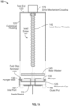
- FIG. 1A illustrates an example of a reservoir for a drug delivery system.
- the reservoir 100 for a drug delivery system may include an elastic sleeve 110, a housing 120, a plunger 130, and a lead screw 140.
- the housing 120 may be a rigid housing or structure with a first end and a second end.
- the housing 120 may be in the shape of a cylinder (i.e., a cylindrical housing) with a first end 123 and a reservoir cap 125, where the reservoir cap 125 is the second end.
- the cylindrical shape of the housing 120 is not limited to a circular cylinder, but may be oval, rectangular, hexagonal or any other tubular shape.
- the first end 123 of the housing 120 is opposite the reservoir cap 125 (or second end).
- the reservoir cap 125 may be coupled to the housing 120 or may be integral to the housing 120.
- the reservoir cap 125 may be coupled to an end of the housing 120 by bonding, welding, friction, snaps (e.g., snap fittings), threads or the like.
- the reservoir cap 125 is stationary with respect to the housing 120.
- the plunger 130 is configured to fit within the housing 120.
- the plunger 130 includes a fluid stop perimeter 133.
- the fluid stop perimeter 133 may have a plunger seal 136.
- the fluid stop perimeter 133 may be a detent or the like in the perimeter of the plunger 130.
- the shape of fluid stop perimeter 133 may be a semi-circular channel, an arched channel, a square channel or a channel of any shape.
- the fluid stop perimeter 133 may be filled or occupied by, in place about the plunger 130.
- the plunger seal 136 may be a leakproof sealing component that contacts the interior of the housing 120.
- the plunger seal 136 may be an O-ring or similar sealing device.
- the plunger seal 136 which is an example of the leakproof sealing component, is configured to engage an internal wall of the housing 120. In order to effectively function as a leakproof sealing component, the plunger seal 136 is configured to engage the entire internal wall of the housing 120.
- the elastic sleeve 110 may be configured as a tube with two open ends.
- the elastic sleeve 110 may be positioned within the housing 120 and have a first tube end coupled to the reservoir cap 136 and a second tube end, opposite the first tube end, coupled to a surface of the plunger 130.
- the elastic sleeve 110 is made from a leakproof material, such as, for example, a silicone rubber, flexible polyvinyl chloride (PVC) tubing, or a similar elastic or flexible material and may have an approximate wall thickness of the elastic sleeve 110 may be approximately 1/2 to 1/4 millimeters or the like.
- the material and the wall thickness of the elastic sleeve 110 may be selected so that the elastic sleeve 110 may fold over on itself as the drug is pushed out. As a result, there is very little hold-up volume of the liquid drug due to the thin walls of elastic sleeve 110. Hold-up volume may be considered an amount of liquid drug that remains after the plunger 130 is no longer able to expel the liquid drug from the reservoir 110.
- the lead screw 140 is configured to pass through a center of the elastic sleeve 110 and a center of the plunger 130.
- the lead screw 140 may have threads, such as lead screw threads 142.
- the number of threads 142 enables precision movement of the plunger 130 and precise control of an amount of liquid drug that is expelled from the reservoir 100.
- the lead screw 140 is operable to move the plunger within the housing 120 via engagement of the lead screw 140 with a drive mechanism coupling 175.
- the drive mechanism coupling 175 may be a link or connection that is operable to transfer forces generated by a drive mechanism to the lead screw 140 in response to which lead screw 140 rotates.
- the lead screw 140 may also be coupled to a base washer 145.
- the base washer 145 is configured with a hole so the lead screw 140 may pass through.
- the hole in the base washer 145 may be threaded to match the lead screw threads 142.
- the base washer 145 is operable to apply pressure to the plunger 130 or relieve pressure depending upon the direction of rotation of the lead screw 140.
- FIG. 1A also shows examples of ports that enable the liquid drug to be input to the reservoir 100, such as inlet port 161, and to be expelled from the reservoir 100, such as outlet port 163.
- inlet port 161 and outlet port 163 are not necessary for understanding the claimed subject matter.
- FIG. 1B illustrates an exemplary initial or prefill position and final position or expelled position of the reservoir shown in FIG. 1A .
- the reservoir 100 has an initial position when the plunger 130 is located at a location near to, or within, the reservoir cap 125 within the housing 120.
- the base washer 145 may be positioned farthest away from the first end 123 of the housing 120.
- the elastic sleeve 110 is shown in a contracted state. A "top portion" of the elastic sleeve 110 is shown coupled between the base washer 145 and the plunger 130, while a “bottom portion” of the elastic sleeve 110 is shown coupled to an exterior of the reservoir cap 125.
- the coupling of the elastic sleeve 110 between the base washer 145 and the plunger 130 may be accomplished by affixing an end portion of the elastic sleeve 110 to a surface of the plunger 130 or to a surface of the base washer 145.
- the lead screw 140 may pass through the elastic sleeve 110.
- a lubricant such as silicone grease, graphite or the like, may be applied to the lead screw 140 to eliminate the potential for the elastic sleeve 110 to catch or otherwise bind on a thread or other part of the lead screw 140.
- the lead screw 140 may extend through the reservoir cap 125 and beyond the length of the housing 120.
- the two elements may be formed as a single component.
- the elastic sleeve 110 may extend to a top portion of the base washer/plunger (closest to the first end 123).
- FIG. 1C illustrates a view of the exemplary reservoir of FIGs. 1A and 1B when it is starting to fill.
- the elastic sleeve 110 When the reservoir 100 is starting to be filled, the elastic sleeve 110 is operable to expand as the plunger 130 is moved away in the plunger direction 101 (as well as movement of the base washer 145 in the same direction as the plunger direction 101) from the reservoir cap 136. The movement of the plunger 130 in direction 101 is in response to rotation of the lead screw 140 in a direction away from the reservoir cap 125.
- the reservoir 100 may be filled with a liquid drug 188 via the inlet port 161.
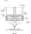
- FIG. 1D illustrates a detailed view of examples of fluid seal locations in the exemplary reservoir of FIGs. 1A-C .
- the detailed view 101 shows the elastic sleeve 110, a portion of the housing 120, the reservoir cap 125, the plunger 130, the liquid drug 188, and different fluid stop/seal locations A-E.
- the elastic sleeve 110 is positioned between the base washer 145 and the plunger 130, and extends radially through a center opening (shown in later examples) of the plunger 130.
- a first part of the elastic sleeve 110 may be sealed at a surface of the plunger 130 facing the base washer 145 and a second part of the elastic sleeve 110 may be sealed at a surface of the reservoir cap 125.
- the liquid drug 188 is shown in a space made by the expansion of the elastic sleeve 110.
- One or more areas for potential leakage in the reservoir 100 may be sealed by different methods at the respective fluid stop/seal locations A-E.
- the elastic sleeve 110, housing 120, plunger 130 and plunger seal 136, and the reservoir cap 125 are all cylindrical so the left and right sides of FIG. 1D may be a single point anywhere along a circumference of the respective component. For example, there may be an intersection between the reservoir cap 125 and the cylindrical housing at which the reservoir cap 125 may be welded, secured by threads, or adhered to the housing 120 at fluid stop/seal location A.
- any potential for leaks around the plunger 130 may be prevented by plunger seal 136 at fluid stop/seal location B which fills the gap between the entire perimeter of the plunger 130 and the internal circumference of the housing 120. Fluid stop/seal locations C and D also extend around the circumference of the respective first part and second part of the elastic sleeve 110. Any liquid drug 188 in the reservoir 100 is limited to the cross hatched areas where the liquid drug 188 is shown.
- the base washer 145 may be threaded and function as a "nut" on the lead screw 140.
- the base washer 145 may be configured to be secured to the plunger 130 via threads on part of the plunger, by adhesive, ultrasonic welding, laser welding, or the like.
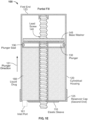
- FIG. 1F illustrates a partially filled view of the exemplary reservoir of FIGs. 1A-1C .
- the reservoir 100 is shown in partially-filled with the plunger 130 positioned within the housing 120 away from the reservoir cap 136.
- the plunger 130 and base washer 145 are located at a location away from the reservoir cap 136 within the housing 120.
- the plunger 130 may traverse along the lead screw 140 away from the reservoir cap 125 (or second end of the rigid housing) causing the elastic sleeve 110 to expand, which creates a void to be filled via the inlet port 161 by the liquid drug 188.
- the inlet port 161 may be configured to pass through the second end 125 of the rigid housing 120 and enable a liquid drug to fill a void between the plunger 130 and the second end 125 when the plunger 130 is moving toward the first end 123.
- the elastic sleeve 110 may have an exterior portion that contacts the liquid drug 188 and an interior portion through which the lead screw 140 may pass.
- the elastic sleeve 110 maintains a boundary between the liquid drug 188 and the leadscrew 140 in the reservoir 100 since the elastic sleeve 110 is leakproof so too is the boundary.
- the lead screw 140 may have a threaded zone along the length (i.e., from the first end 123 of the housing 120 to the reservoir cap 125) of the lead screw 140 and the threaded zone is outside of any fluid zone (i.e., the cross-hatched areas where the liquid drug 188 is located).
- the elastic sleeve 110 When the liquid drug is to be expelled from the reservoir 100, the elastic sleeve 110 is operable to contract as the base washer 145 and the plunger 130 are moved toward the reservoir cap 136. Since the lead screw 140 passes through the elastic sleeve 110, the lead screw 140 may contact the interior portion of the elastic sleeve 110.
- the interior portion (i.e., the portion of the elastic sleeve 110 closest to the lead screw 140) of the elastic sleeve 110 may have a lubricant, such as silicone grease or the like.
- the elastic sleeve 100 surrounds the leadscrew 140 and may be coupled to a surface (e.g., a top surface closest to the base washer 145) of the plunger 130 and to a surface of the second end (e.g., the reservoir cap 125) of the rigid housing 120.
- the elastic sleeve 110 may be configured in such a manner that a force is needed to cause the elastic sleeve 100 to expand.
- the force may be applied by the liquid drug 188 flowing into the reservoir 100, by the plunger 130 and base washer 145 pulling the elastic sleeve 100 away from the reservoir cap 125 in response to a rotation of the lead screw 140, or by a combination of both the liquid drug flowing into the reservoir 100 and the pulling by the plunger 130 and base washer 145.
- the elastic sleeve 110 was elastic, little or no force is required to be applied by an external source to contract the elastic sleeve 110 back.
- While threading the base washer and/or the plunger may provide a solution to prevent drainage after filling, other mechanisms and/or techniques are envisioned to lock the base washer 145 and/or plunger in place and prevent the elastic sleeve 100 from contracting, which prevents leakage from the reservoir.
- FIG. 2A illustrates a detailed view of an arrangement of a plunger and base washer usable in the examples of a reservoir shown in earlier embodiments.
- FIG. 2A shows a locking feature usable in the arrangement 221 of the plunger 230 and base washer 245.
- a locking feature is a base washer lock 247 that is configured to lock (in one direction in some examples) the base washer 245 against the lead screw 240.
- the base washer lock 247 may be a keying device, a square screw fitted into a squared inset of the base washer 245, or the like.
- a purpose of the locking feature is to prevent the base washer 245 from applying pressure to the plunger 230 without positive rotational movement by the lead screw 240 or in response to vibrations or movement of the user. As a result, inadvertent expulsion of the liquid drug from the reservoir may be avoided.
- the base washer 245 may be molded or 3-D printed with the base washer lock 247 in place so as to avoid having to assemble the base washer 245 and the base washer lock 247.
- FIG. 2B illustrates a general view of the example of a reservoir of FIG. 2A .
- the plunger seals 236 and the elastic sleeve 210 seal a portion of the reservoir 220 between the plunger 230 and the reservoir cap 225.
- the reservoir 220 is shown with an open top that allows the base washer lock 247, which may be a threaded nut, to be accessed (as shown by the pair of arrows).
- the open top of the reservoir 220 allows for several options to lock or otherwise engage the base washer lock 247 once filling of the reservoir 220 with the liquid drug 288 is completed.
- the base washer lock 247 performs two functions: 1) it permits the plunger 230 and base washer 245 to rise freely in the direction away from the reservoir cap 225 along the length of the lead screw 240 when the reservoir 220 is being filled with a liquid drug 288, and 2) enables more precise control of the amount of liquid drug 288 being dispensed by locking to the lead screw 240 due to the lead screw 240 having to drive the base washer 247 downward toward the reservoir cap 225.
- the threads may engage threads of the lead screw 240.
- the lead screw 240 may be operable to move the threaded nut enabling the elastic sleeve 210 to expand and be filled with a liquid drug via the inlet port or to contract and expel the liquid drug from the elastic sleeve 210.
- FIG. 3 illustrates a number of features related to an exemplary locking feature according to the disclosed subject matter.
- a reservoir 300 is shown and exemplary locking features are shown in more detail.
- arrow 333 points to a side view of the lead screw 340 which shows a keyway 343 extending down the length of the lead screw 340.
- a keyed cam 346 that has a key 347 that is configured to slide down the keyway 343 of the lead screw 340 and, optionally, a protrusion 349.
- the keyed cam 346 is described further with reference to a later example.
- base washer 345 is circular with a center hole 351 through which may pass the lead screw 340.
- the base washer 345 may also be elliptical with a hole that permits the lead screw 340 to pass.
- the base washer 345 may further include a first ratchet device 352 and a second ratchet device 354.
- the first ratchet device 352 and the second ratchet device 354 may be built into, molded into, 3D printed, or otherwise fabricated, while the base washer 345 is fabricated.
- the first ratchet device 352 and the second ratchet device 354 may be one-way ratchet features that may be engaged only when the reservoir 300 is filled with the liquid drug and may be configured to permit the base washer 345 to move toward the reservoir cap (shown in previous examples) when expelling the liquid drug from the filled reservoir 300.
- FIG. 4A illustrates an exemplary locking feature for a drug delivery device reservoir according to the disclosed subject matter.
- the base washer 445 is similar to the base washers of the examples of FIGs. 1A-3 .
- the base washer 445 has a center opening through which passes a keyed lead screw 440.
- a keyed cam 446 Positioned over the base washer 445 is a keyed cam 446.
- the keyed cam 446 is also circular and has a center opening into which extends a key 448 along the axis M. Extending from the perimeter of the keyed cam 446 is a protrusion 449.
- the protrusion 449 may be approximately at a 45 degree angle with the axis M.
- the base washer 445 may also have pivot points, pivot point 447A and pivot point 448A.
- the keyed cam 446 is operable to rotate with the keyed lead screw 440.
- the keyed cam 446 may be operable to rotate in the same direction.
- the keyed cam 446 may rotate as shown by Arrow R.
- FIG. 4B illustrates further details of the exemplary locking feature illustrated in FIG. 4A.
- FIG. 4B illustrates an unlocked state of the locking assembly 450.
- a locking assembly 450 is shown positioned over the keyed cam 446 and about the keyed lead screw 440.
- the locking assembly 450 includes threaded locking arms 455A, 455B, a spring 458, and a pawl 457.
- the threaded locking arms 455A and 455B include edges that, when in contact with the keyed lead screw 440, prevent the base washer 445 from moving upwards or downwards on the keyed lead screw 440.
- the threaded locking arms 455A and 455B may couple respectively to the pivot points 447A and 447B.
- the pawl 457 In the unlocked state of FIG. 4B , the pawl 457 is positioned between the respective threaded locking arms 455A and 455B which prevents the threaded locking arms 455A and 455B from contacting the keyed lead screw 440.
- the base washer 445 In the unlocked state, the base washer 445 is operable to be driven downward by the keyed lead screw 440.
- the spring 458 may be expanded due to the force applied by the pawl 457.
- the pawl 457 may be spring-loaded with a spring having sufficient force to position the pawl 457 between the threaded locking arms 455A and 455B by overcoming the force of the spring 458.
- other mechanisms besides a spring may be used to move the pawl 457.
- the locking assembly 450 as well as the base washer 445 and keyed cam 446 may travel up and down the keyed lead screw 440 as the reservoir is being filled or as liquid drug is being expelled. In an alternative example, the locking assembly 450 may travel up and down the keyed lead screw 440.
- the wearable drug delivery device While in the unlocked position of FIG. 4B , the wearable drug delivery device is operable to expel any liquid drug from the reservoir for delivery to a user.
- FIG. 4C illustrates further details of the exemplary locking feature illustrated in FIGs. 4A and 4B .
- the keyed cam 446 also rotates and the protrusion 449 circles around and engages the pawl 457.
- the keyed lead screw 440 has sufficient torque and the shape of the protrusion 449 that when the protrusion 449 engages the pawl 457, the pawl 457 pushed out from between the threaded locking arms 455A and 455B.
- the threaded locking arms 455A and 455B clamp against, or insert ratchets in threads of, the keyed lead screw 440 and prevents additional movement of the base washer 445 up and down the lead screw 440.
- the base washer 445 may be held in place by the locking assembly 450.
- FIG. 5 illustrates a block diagram of an exemplary wearable drug delivery device suitable for using the reservoir illustrated and described herein.
- the wearable drug delivery device 500 may include control circuitry 510, a power supply 520, a drive mechanism 540, a drive mechanism coupling 543, and a reservoir 550.
- the wearable drug delivery device 500 may be a wearable device that is worn on the body of the user.
- the wearable drug delivery device 500 may be directly coupled to a user (i.e., directly attached to a body part and/or skin of the user via an adhesive, or the like).
- a surface of the wearable drug delivery device 500 may include an adhesive to facilitate attachment to the skin of a user.
- the reservoir 550 may store a liquid drug.
- the device 500 is described with reference to delivery of insulin and the use of an AID algorithm, the device 500 may be operable to implement a drug delivery regimen via a medication delivery algorithm using a number of different liquid or therapeutic drugs.
- Examples of a liquid drug may be or include any drug in liquid form capable of being administered by a drug delivery device via a subcutaneous cannula, including, for example, insulin, glucagon-like peptide-1 (GLP-1), pramlintide, glucagon, co-formulations of two or more of GLP-1, pramlintide, and insulin; as well as pain relief drugs, such as opioids or narcotics (e.g., morphine, or the like), methadone, arthritis drugs, hormones, such as estrogen and testosterone, blood pressure medicines, chemotherapy drugs, fertility drugs, or the like.
- GLP-1 glucagon-like peptide-1
- pramlintide glucagon-like peptide-1
- glucagon co-formulations of two or more of GLP-1, pramlintide, and insulin
- pain relief drugs such as opioids or narcotics (e.g., morphine, or the like), methadone, arthritis drugs, hormones
- the elastic sleeve of this disclosure may be made of an elastomeric material having an elongation at break of at least 300% more preferably at least 500%.
- the drive mechanism 540 may be responsive to signals from the control circuitry and may include a number of mechanical elements such as gears, gear trains and the like.
- the drive mechanism 540 may be operable to drive a lead screw such as those described in earlier examples.
- a drive mechanism coupling 543 may couple the drive mechanism 540 to the lead screw and to the reservoir 550.
- the drive mechanism coupling 543 may translate linear motion into rotary motion, or the like.
- the drive mechanism coupling 543 may have the structural elements that enable a precise amount of a liquid drug stored in the reservoir 550 to be expelled from the reservoir 550 via a fluid pathway 560 from the wearable drug delivery device 500.
- the power supply 520 may be an electrical power source, such as a battery, a super capacitor, an energy harvesting circuit or the like.
- the power supply 520 may be configured to last several hours, several days or the like.
- the power supply 520 may be replaceable and/or rechargeable via wired connections or wireless connections.
- the wearable drug delivery device 500 may include control circuitry 510 that may be implemented in hardware, software, or any combination thereof.
- the control circuitry 510 may, for example, be a microprocessor, a logic circuit, a field programmable gate array (FPGA), an application specific integrated circuit (ASIC) or a microprocessor coupled to a memory.
- the control circuitry 510 may be operable to perform a number of functions, such as executing a control application stored in the memory (not shown) to enable the functions described herein, such as rotation of the lead screw within the reservoir 550.
- a type of medication delivery algorithm may include an "artificial pancreas" algorithm-based system, or more generally, an artificial pancreas (AP) application.
- AP artificial pancreas
- An AP application may be configured to provide automatic delivery of insulin based on an analyte sensor input, such as signals received from an analyte sensor, such as a continuous blood glucose monitor, ketone sensor, or the like.
- the signals from the analyte sensor may contain blood glucose measurement values, timestamps, or the like.
- the housing of the reservoir as well as the plunger mentioned in this disclosure may both have a cylindrical cross-sectional shape
- the housing and the plunger of the present disclosure may also have a non-cylindrical cross-sectional shape. This has the advantage that the plunger cannot rotate within the housing when the lead screw rotates to advance the plunger within the housing.
- a cylindrical shape is also possible since the threading of the lead screw mainly exerts axial forces on the plunger or the base washer, respectively, if the pitch of the threading is not too large, such that the plunger does not rotate when the lead screw rotates.
Landscapes
- Health & Medical Sciences (AREA)
- Vascular Medicine (AREA)
- Engineering & Computer Science (AREA)
- Anesthesiology (AREA)
- Biomedical Technology (AREA)
- Heart & Thoracic Surgery (AREA)
- Hematology (AREA)
- Life Sciences & Earth Sciences (AREA)
- Animal Behavior & Ethology (AREA)
- General Health & Medical Sciences (AREA)
- Public Health (AREA)
- Veterinary Medicine (AREA)
- Infusion, Injection, And Reservoir Apparatuses (AREA)
Abstract
Disclosed are techniques, devices and systems that provide a compact reservoir and plunger arrangement. In the disclosed examples, a reservoir may include a housing, a plunger, a lead screw and an elastic sleeve. The housing may have a first end and a second end. The plunger may be configured to fit within the housing. The leadscrew may be coupled to the plunger. The elastic sleeve may surround the leadscrew and be coupled to a surface of the plunger and to a surface of the second end of the housing. The elastic sleeve is leakproof.
Description
- For wearable medical devices, physical size is a major driver of the overall impact of therapy on the patients employing them. One of the largest elements in a complex and space-constrained medical device (such as an insulin pump) is the reservoir and plunger arrangement. To maintain a small device footprint, a design objective is to optimize the volume occupied by the reservoir and plunger of a drug delivery device.
- Using a screw to drive a plunger is advantageous for accurate dispensing from a reservoir. When the screw is in line with the plunger, it effectively doubles the length of the plunger making the packaging/overall size larger. Putting the screw inside of the reservoir is challenging because sealing on the threads of the plunger in addition to the O-ring on the plunger side wall is challenging both technically and for manufacturing. It would be helpful to have a small, low-cost, micro-actuator with reciprocal motion, maximum output force output for a given electrical input.
- The present invention is directed to a drug delivery system as defined in the enclosed claims. This Summary is provided to introduce a selection of concepts in a simplified form that are further described below in the Detailed Description. This Summary is not intended to identify key features or essential features of the claimed subject matter, nor is it intended as an aid in determining the scope of the claimed subject matter.
- According to an example of the disclosed subject matter, a reservoir for a drug delivery system is disclosed. The reservoir may include a cylindrical housing, a plunger, an elastic sleeve, a lead screw and a reservoir cap. The plunger may be configured to fit within the cylindrical housing. The elastic sleeve may be within the cylindrical housing and be coupled to a surface of the plunger. The elastic sleeve is leakproof. The lead screw may pass through a center of the elastic sleeve and a center of the plunger. The reservoir cap may be coupled to the cylindrical housing.
- According to an example of the disclosed subject matter, another reservoir for a drug delivery system is disclosed. The reservoir may include a rigid housing, a plunger, a lead screw and an elastic sleeve. The rigid housing may have a first end and a second end. The plunger may be configured to fit within the rigid housing. The leadscrew may be coupled to the plunger. The elastic sleeve may surround the leadscrew and be coupled to a surface of the plunger and to a surface of the second end of the rigid housing. The elastic sleeve is leakproof.
-
-
FIG. 1A illustrates an example of a reservoir for a drug delivery system according to the disclosed subject matter. -
FIG. 1B illustrates an exemplary initial or prefill position and final position or expelled position of the reservoir shown inFIG. 1A . -
FIG. 1C illustrates an exploded view of the example of the reservoir ofFIG. 1A . -
FIG. 1D illustrates an exploded view of the example of the reservoir ofFIG. 1A . - FIG. 1F illustrates an exploded view of the example of the reservoir of
FIG. 1A . -
FIG. 2A illustrates a detailed view of an arrangement of a plunger and base washer usable in the examples of a reservoir shown in earlier embodiments. -
FIG. 2B illustrates a general view of the example of a reservoir ofFIG. 2A . -
FIG. 3 illustrates a number of features related to an exemplary locking feature according to the disclosed subject matter. -
FIG. 4A illustrates an exemplary locking feature for a drug delivery device reservoir according to the disclosed subject matter. -
FIG. 4B illustrates further details of the exemplary locking feature illustrated inFIG. 4A . -
FIG. 4C illustrates further details of the exemplary locking feature illustrated inFIGs. 4A and 4B . -
FIG. 5 shows a block diagram of an exemplary wearable drug delivery device suitable for using the reservoir illustrated and described with reference toFIGs. 1A-4C . - The following discussion provides a detailed discussion of a drug delivery device reservoir. The reservoir examples described herein may include various features related to an elastic sleeve used to enable a lead screw to pass through an interior of the reservoir.
-
FIG. 1A illustrates an example of a reservoir for a drug delivery system. InFIG. 1A , thereservoir 100 for a drug delivery system may include anelastic sleeve 110, ahousing 120, aplunger 130, and alead screw 140. - The
housing 120 may be a rigid housing or structure with a first end and a second end. For example, thehousing 120 may be in the shape of a cylinder (i.e., a cylindrical housing) with afirst end 123 and areservoir cap 125, where thereservoir cap 125 is the second end. The cylindrical shape of thehousing 120 is not limited to a circular cylinder, but may be oval, rectangular, hexagonal or any other tubular shape. Thefirst end 123 of thehousing 120 is opposite the reservoir cap 125 (or second end). Thereservoir cap 125 may be coupled to thehousing 120 or may be integral to thehousing 120. For example, thereservoir cap 125 may be coupled to an end of thehousing 120 by bonding, welding, friction, snaps (e.g., snap fittings), threads or the like. Thereservoir cap 125 is stationary with respect to thehousing 120. - The
plunger 130 is configured to fit within thehousing 120. Theplunger 130 includes afluid stop perimeter 133. Thefluid stop perimeter 133 may have aplunger seal 136. For example, thefluid stop perimeter 133 may be a detent or the like in the perimeter of theplunger 130. The shape offluid stop perimeter 133 may be a semi-circular channel, an arched channel, a square channel or a channel of any shape. Thefluid stop perimeter 133 may be filled or occupied by, in place about theplunger 130. Theplunger seal 136 may be a leakproof sealing component that contacts the interior of thehousing 120. For example, theplunger seal 136 may be an O-ring or similar sealing device. In addition to occupying thefluid stop perimeter 133, theplunger seal 136, which is an example of the leakproof sealing component, is configured to engage an internal wall of thehousing 120. In order to effectively function as a leakproof sealing component, theplunger seal 136 is configured to engage the entire internal wall of thehousing 120. - The
elastic sleeve 110 may be configured as a tube with two open ends. For example, theelastic sleeve 110 may be positioned within thehousing 120 and have a first tube end coupled to thereservoir cap 136 and a second tube end, opposite the first tube end, coupled to a surface of theplunger 130. Theelastic sleeve 110 is made from a leakproof material, such as, for example, a silicone rubber, flexible polyvinyl chloride (PVC) tubing, or a similar elastic or flexible material and may have an approximate wall thickness of theelastic sleeve 110 may be approximately 1/2 to 1/4 millimeters or the like. The material and the wall thickness of theelastic sleeve 110 may be selected so that theelastic sleeve 110 may fold over on itself as the drug is pushed out. As a result, there is very little hold-up volume of the liquid drug due to the thin walls ofelastic sleeve 110. Hold-up volume may be considered an amount of liquid drug that remains after theplunger 130 is no longer able to expel the liquid drug from thereservoir 110. - The
lead screw 140 is configured to pass through a center of theelastic sleeve 110 and a center of theplunger 130. Thelead screw 140 may have threads, such aslead screw threads 142. The number ofthreads 142 enables precision movement of theplunger 130 and precise control of an amount of liquid drug that is expelled from thereservoir 100. Thelead screw 140 is operable to move the plunger within thehousing 120 via engagement of thelead screw 140 with adrive mechanism coupling 175. Thedrive mechanism coupling 175 may be a link or connection that is operable to transfer forces generated by a drive mechanism to thelead screw 140 in response to whichlead screw 140 rotates. - In the illustrated example, the
lead screw 140 may also be coupled to abase washer 145. In an example, thebase washer 145 is configured with a hole so thelead screw 140 may pass through. The hole in thebase washer 145 may be threaded to match thelead screw threads 142. When threaded, thebase washer 145 is operable to apply pressure to theplunger 130 or relieve pressure depending upon the direction of rotation of thelead screw 140. - The liquid drug may flow into and out of the
reservoir 100.FIG. 1A also shows examples of ports that enable the liquid drug to be input to thereservoir 100, such asinlet port 161, and to be expelled from thereservoir 100, such asoutlet port 163. Other than being able to enable the liquid drug to pass into thereservoir 100 and permit the liquid drug to pass from thereservoir 100, the details ofinlet port 161 andoutlet port 163 are not necessary for understanding the claimed subject matter. -
FIG. 1B illustrates an exemplary initial or prefill position and final position or expelled position of the reservoir shown inFIG. 1A . As shown inFIG. 1B , thereservoir 100 has an initial position when theplunger 130 is located at a location near to, or within, thereservoir cap 125 within thehousing 120. Thebase washer 145 may be positioned farthest away from thefirst end 123 of thehousing 120. Theelastic sleeve 110 is shown in a contracted state. A "top portion" of theelastic sleeve 110 is shown coupled between thebase washer 145 and theplunger 130, while a "bottom portion" of theelastic sleeve 110 is shown coupled to an exterior of thereservoir cap 125. The coupling of theelastic sleeve 110 between thebase washer 145 and theplunger 130 may be accomplished by affixing an end portion of theelastic sleeve 110 to a surface of theplunger 130 or to a surface of thebase washer 145. Thelead screw 140 may pass through theelastic sleeve 110. A lubricant, such as silicone grease, graphite or the like, may be applied to thelead screw 140 to eliminate the potential for theelastic sleeve 110 to catch or otherwise bind on a thread or other part of thelead screw 140. In some examples, thelead screw 140 may extend through thereservoir cap 125 and beyond the length of thehousing 120. - While the
base washer 145 and theplunger 130 are called out separately, the two elements may be formed as a single component. When thebase washer 145 and theplunger 130 are formed as a single component (i.e., base washer/plunger), theelastic sleeve 110 may extend to a top portion of the base washer/plunger (closest to the first end 123). -
FIG. 1C illustrates a view of the exemplary reservoir ofFIGs. 1A and1B when it is starting to fill. - When the
reservoir 100 is starting to be filled, theelastic sleeve 110 is operable to expand as theplunger 130 is moved away in the plunger direction 101 (as well as movement of thebase washer 145 in the same direction as the plunger direction 101) from thereservoir cap 136. The movement of theplunger 130 indirection 101 is in response to rotation of thelead screw 140 in a direction away from thereservoir cap 125. In one or more examples, thereservoir 100 may be filled with aliquid drug 188 via theinlet port 161. -
FIG. 1D illustrates a detailed view of examples of fluid seal locations in the exemplary reservoir ofFIGs. 1A-C . - The
detailed view 101 shows theelastic sleeve 110, a portion of thehousing 120, thereservoir cap 125, theplunger 130, theliquid drug 188, and different fluid stop/seal locations A-E. As shown in more detail inFIG. 1D , theelastic sleeve 110 is positioned between thebase washer 145 and theplunger 130, and extends radially through a center opening (shown in later examples) of theplunger 130. In this example, a first part of theelastic sleeve 110 may be sealed at a surface of theplunger 130 facing thebase washer 145 and a second part of theelastic sleeve 110 may be sealed at a surface of thereservoir cap 125. Theliquid drug 188 is shown in a space made by the expansion of theelastic sleeve 110. - One or more areas for potential leakage in the
reservoir 100 may be sealed by different methods at the respective fluid stop/seal locations A-E. Note that theelastic sleeve 110,housing 120,plunger 130 andplunger seal 136, and thereservoir cap 125 are all cylindrical so the left and right sides ofFIG. 1D may be a single point anywhere along a circumference of the respective component. For example, there may be an intersection between thereservoir cap 125 and the cylindrical housing at which thereservoir cap 125 may be welded, secured by threads, or adhered to thehousing 120 at fluid stop/seal location A. Any potential for leaks around theplunger 130 may be prevented byplunger seal 136 at fluid stop/seal location B which fills the gap between the entire perimeter of theplunger 130 and the internal circumference of thehousing 120. Fluid stop/seal locations C and D also extend around the circumference of the respective first part and second part of theelastic sleeve 110. Anyliquid drug 188 in thereservoir 100 is limited to the cross hatched areas where theliquid drug 188 is shown. Thebase washer 145 may be threaded and function as a "nut" on thelead screw 140. Thebase washer 145 may be configured to be secured to theplunger 130 via threads on part of the plunger, by adhesive, ultrasonic welding, laser welding, or the like. - FIG. 1F illustrates a partially filled view of the exemplary reservoir of
FIGs. 1A-1C . - In the example of
FIG. 1E , thereservoir 100 is shown in partially-filled with theplunger 130 positioned within thehousing 120 away from thereservoir cap 136. When thereservoir 100 is filled, theplunger 130 andbase washer 145 are located at a location away from thereservoir cap 136 within thehousing 120. To arrive at the state shown inFIG. 1E , theplunger 130 may traverse along thelead screw 140 away from the reservoir cap 125 (or second end of the rigid housing) causing theelastic sleeve 110 to expand, which creates a void to be filled via theinlet port 161 by theliquid drug 188. Conversely, when the liquid drug is expelled from thereservoir 100, theplunger 130 traverses in an opposite direction and theelastic sleeve 110 contracts all the while maintaining a leakproof boundary for thelead screw 140. Theinlet port 161 may be configured to pass through thesecond end 125 of therigid housing 120 and enable a liquid drug to fill a void between theplunger 130 and thesecond end 125 when theplunger 130 is moving toward thefirst end 123. - The
elastic sleeve 110 may have an exterior portion that contacts theliquid drug 188 and an interior portion through which thelead screw 140 may pass. Theelastic sleeve 110 maintains a boundary between theliquid drug 188 and theleadscrew 140 in thereservoir 100 since theelastic sleeve 110 is leakproof so too is the boundary. Thelead screw 140 may have a threaded zone along the length (i.e., from thefirst end 123 of thehousing 120 to the reservoir cap 125) of thelead screw 140 and the threaded zone is outside of any fluid zone (i.e., the cross-hatched areas where theliquid drug 188 is located). When the liquid drug is to be expelled from thereservoir 100, theelastic sleeve 110 is operable to contract as thebase washer 145 and theplunger 130 are moved toward thereservoir cap 136. Since thelead screw 140 passes through theelastic sleeve 110, thelead screw 140 may contact the interior portion of theelastic sleeve 110. The interior portion (i.e., the portion of theelastic sleeve 110 closest to the lead screw 140) of theelastic sleeve 110 may have a lubricant, such as silicone grease or the like. In an example, theelastic sleeve 100 surrounds theleadscrew 140 and may be coupled to a surface (e.g., a top surface closest to the base washer 145) of theplunger 130 and to a surface of the second end (e.g., the reservoir cap 125) of therigid housing 120. - In the examples 1A-1E, the
elastic sleeve 110 may be configured in such a manner that a force is needed to cause theelastic sleeve 100 to expand. The force may be applied by theliquid drug 188 flowing into thereservoir 100, by theplunger 130 andbase washer 145 pulling theelastic sleeve 100 away from thereservoir cap 125 in response to a rotation of thelead screw 140, or by a combination of both the liquid drug flowing into thereservoir 100 and the pulling by theplunger 130 andbase washer 145. Conversely, because theelastic sleeve 110 was elastic, little or no force is required to be applied by an external source to contract theelastic sleeve 110 back. Only the threads on the threadedbase washer 145 described above enable theelastic sleeve 110 to maintain its expanded state. Without the threadedbase washer 145 being there, theelastic sleeve 110 would apply pressure toliquid drug 188 and may cause theliquid drug 188 to leak from thereservoir 100. - While threading the base washer and/or the plunger may provide a solution to prevent drainage after filling, other mechanisms and/or techniques are envisioned to lock the
base washer 145 and/or plunger in place and prevent theelastic sleeve 100 from contracting, which prevents leakage from the reservoir. -
FIG. 2A illustrates a detailed view of an arrangement of a plunger and base washer usable in the examples of a reservoir shown in earlier embodiments. -
FIG. 2A shows a locking feature usable in thearrangement 221 of theplunger 230 andbase washer 245. In this example, instead of the base washer being threaded, a locking feature is abase washer lock 247 that is configured to lock (in one direction in some examples) thebase washer 245 against thelead screw 240. Thebase washer lock 247 may be a keying device, a square screw fitted into a squared inset of thebase washer 245, or the like. A purpose of the locking feature is to prevent thebase washer 245 from applying pressure to theplunger 230 without positive rotational movement by thelead screw 240 or in response to vibrations or movement of the user. As a result, inadvertent expulsion of the liquid drug from the reservoir may be avoided. Thebase washer 245 may be molded or 3-D printed with thebase washer lock 247 in place so as to avoid having to assemble thebase washer 245 and thebase washer lock 247. -
FIG. 2B illustrates a general view of the example of a reservoir ofFIG. 2A . - The plunger seals 236 and the
elastic sleeve 210 seal a portion of thereservoir 220 between theplunger 230 and thereservoir cap 225. Thereservoir 220 is shown with an open top that allows thebase washer lock 247, which may be a threaded nut, to be accessed (as shown by the pair of arrows). The open top of thereservoir 220 allows for several options to lock or otherwise engage thebase washer lock 247 once filling of thereservoir 220 with theliquid drug 288 is completed. Thebase washer lock 247 performs two functions: 1) it permits theplunger 230 andbase washer 245 to rise freely in the direction away from thereservoir cap 225 along the length of thelead screw 240 when thereservoir 220 is being filled with aliquid drug 288, and 2) enables more precise control of the amount ofliquid drug 288 being dispensed by locking to thelead screw 240 due to thelead screw 240 having to drive thebase washer 247 downward toward thereservoir cap 225. - In an example of when the
base washer 247 is a threaded nut, the threads may engage threads of thelead screw 240. Thelead screw 240 may be operable to move the threaded nut enabling theelastic sleeve 210 to expand and be filled with a liquid drug via the inlet port or to contract and expel the liquid drug from theelastic sleeve 210. -
FIG. 3 illustrates a number of features related to an exemplary locking feature according to the disclosed subject matter. - In
FIG. 3 , areservoir 300 is shown and exemplary locking features are shown in more detail. For example,arrow 333 points to a side view of thelead screw 340 which shows akeyway 343 extending down the length of thelead screw 340. To the upper right is a top view of akeyed cam 346 that has a key 347 that is configured to slide down thekeyway 343 of thelead screw 340 and, optionally, aprotrusion 349. Thekeyed cam 346 is described further with reference to a later example. -
Arrow 335 points to a top view ofbase washer 345. In this example,base washer 345 is circular with acenter hole 351 through which may pass thelead screw 340. However, thebase washer 345 may also be elliptical with a hole that permits thelead screw 340 to pass. Thebase washer 345 may further include afirst ratchet device 352 and asecond ratchet device 354. Thefirst ratchet device 352 and thesecond ratchet device 354 may be built into, molded into, 3D printed, or otherwise fabricated, while thebase washer 345 is fabricated. - The
first ratchet device 352 and thesecond ratchet device 354 may be one-way ratchet features that may be engaged only when thereservoir 300 is filled with the liquid drug and may be configured to permit thebase washer 345 to move toward the reservoir cap (shown in previous examples) when expelling the liquid drug from the filledreservoir 300. -
FIG. 4A illustrates an exemplary locking feature for a drug delivery device reservoir according to the disclosed subject matter. - The
base washer 445 is similar to the base washers of the examples ofFIGs. 1A-3 . In the example ofFIG. 4A , thebase washer 445 has a center opening through which passes akeyed lead screw 440. Positioned over thebase washer 445 is akeyed cam 446. Thekeyed cam 446 is also circular and has a center opening into which extends a key 448 along the axis M. Extending from the perimeter of the keyedcam 446 is aprotrusion 449. Theprotrusion 449 may be approximately at a 45 degree angle with the axis M. Thebase washer 445 may also have pivot points,pivot point 447A and pivot point 448A. Thekeyed cam 446 is operable to rotate with thekeyed lead screw 440. For example, as thekeyed lead screw 440 rotates in a direction, thekeyed cam 446 may be operable to rotate in the same direction. Thekeyed cam 446 may rotate as shown by Arrow R. -
FIG. 4B illustrates further details of the exemplary locking feature illustrated inFIG. 4A. FIG. 4B illustrates an unlocked state of the lockingassembly 450. InFIG. 4B , a lockingassembly 450 is shown positioned over thekeyed cam 446 and about the keyedlead screw 440. The lockingassembly 450 includes threaded lockingarms spring 458, and apawl 457. The threadedlocking arms keyed lead screw 440, prevent thebase washer 445 from moving upwards or downwards on thekeyed lead screw 440. The threadedlocking arms - In the unlocked state of
FIG. 4B , thepawl 457 is positioned between the respective threaded lockingarms arms keyed lead screw 440. In the unlocked state, thebase washer 445 is operable to be driven downward by the keyedlead screw 440. Thespring 458 may be expanded due to the force applied by thepawl 457. For example, thepawl 457 may be spring-loaded with a spring having sufficient force to position thepawl 457 between the threaded lockingarms spring 458. Of course, other mechanisms besides a spring may be used to move thepawl 457. In the unlocked state ofFIG. 4B , for example, the lockingassembly 450 as well as thebase washer 445 and keyedcam 446 may travel up and down the keyedlead screw 440 as the reservoir is being filled or as liquid drug is being expelled. In an alternative example, the lockingassembly 450 may travel up and down the keyedlead screw 440. - While in the unlocked position of
FIG. 4B , the wearable drug delivery device is operable to expel any liquid drug from the reservoir for delivery to a user. -
FIG. 4C illustrates further details of the exemplary locking feature illustrated inFIGs. 4A and 4B . As the keyedlead screw 440 rotates, thekeyed cam 446 also rotates and theprotrusion 449 circles around and engages thepawl 457. Thekeyed lead screw 440 has sufficient torque and the shape of theprotrusion 449 that when theprotrusion 449 engages thepawl 457, thepawl 457 pushed out from between the threaded lockingarms pawl 457 being out from between the threaded lockingarms arms keyed lead screw 440 and prevents additional movement of thebase washer 445 up and down thelead screw 440. In the locked state, thebase washer 445 may be held in place by the lockingassembly 450. - Mechanisms and techniques for maintaining position of the plunger and base washer other than a combination of the keyed
cam 446,pawl 457 or threaded lockingarms U.S. Provisional Application No.: 63/375,986, filed on September 16, 2022 -
FIG. 5 illustrates a block diagram of an exemplary wearable drug delivery device suitable for using the reservoir illustrated and described herein. - The wearable
drug delivery device 500 may includecontrol circuitry 510, apower supply 520, adrive mechanism 540, adrive mechanism coupling 543, and areservoir 550. The wearabledrug delivery device 500 may be a wearable device that is worn on the body of the user. The wearabledrug delivery device 500 may be directly coupled to a user (i.e., directly attached to a body part and/or skin of the user via an adhesive, or the like). In an example, a surface of the wearabledrug delivery device 500 may include an adhesive to facilitate attachment to the skin of a user. - The
reservoir 550, such as those described herein, may store a liquid drug. In addition, while thedevice 500 is described with reference to delivery of insulin and the use of an AID algorithm, thedevice 500 may be operable to implement a drug delivery regimen via a medication delivery algorithm using a number of different liquid or therapeutic drugs. Examples of a liquid drug may be or include any drug in liquid form capable of being administered by a drug delivery device via a subcutaneous cannula, including, for example, insulin, glucagon-like peptide-1 (GLP-1), pramlintide, glucagon, co-formulations of two or more of GLP-1, pramlintide, and insulin; as well as pain relief drugs, such as opioids or narcotics (e.g., morphine, or the like), methadone, arthritis drugs, hormones, such as estrogen and testosterone, blood pressure medicines, chemotherapy drugs, fertility drugs, or the like. - The elastic sleeve of this disclosure may be made of an elastomeric material having an elongation at break of at least 300% more preferably at least 500%.
- The
drive mechanism 540 may be responsive to signals from the control circuitry and may include a number of mechanical elements such as gears, gear trains and the like. Thedrive mechanism 540 may be operable to drive a lead screw such as those described in earlier examples. - A
drive mechanism coupling 543 may couple thedrive mechanism 540 to the lead screw and to thereservoir 550. Thedrive mechanism coupling 543 may translate linear motion into rotary motion, or the like. Thedrive mechanism coupling 543 may have the structural elements that enable a precise amount of a liquid drug stored in thereservoir 550 to be expelled from thereservoir 550 via afluid pathway 560 from the wearabledrug delivery device 500. - The
power supply 520 may be an electrical power source, such as a battery, a super capacitor, an energy harvesting circuit or the like. Thepower supply 520 may be configured to last several hours, several days or the like. Thepower supply 520 may be replaceable and/or rechargeable via wired connections or wireless connections. - The wearable
drug delivery device 500 may includecontrol circuitry 510 that may be implemented in hardware, software, or any combination thereof. Thecontrol circuitry 510 may, for example, be a microprocessor, a logic circuit, a field programmable gate array (FPGA), an application specific integrated circuit (ASIC) or a microprocessor coupled to a memory. Thecontrol circuitry 510 may be operable to perform a number of functions, such as executing a control application stored in the memory (not shown) to enable the functions described herein, such as rotation of the lead screw within thereservoir 550. - A type of medication delivery algorithm (MDA) may include an "artificial pancreas" algorithm-based system, or more generally, an artificial pancreas (AP) application. For ease of discussion, the computer programs and computer applications that implement the medication delivery algorithms or applications may be referred to herein as an "AP application." An AP application may be configured to provide automatic delivery of insulin based on an analyte sensor input, such as signals received from an analyte sensor, such as a continuous blood glucose monitor, ketone sensor, or the like. The signals from the analyte sensor may contain blood glucose measurement values, timestamps, or the like.
- Although the housing of the reservoir as well as the plunger mentioned in this disclosure may both have a cylindrical cross-sectional shape, it should be understood that the housing and the plunger of the present disclosure may also have a non-cylindrical cross-sectional shape. This has the advantage that the plunger cannot rotate within the housing when the lead screw rotates to advance the plunger within the housing. A cylindrical shape is also possible since the threading of the lead screw mainly exerts axial forces on the plunger or the base washer, respectively, if the pitch of the threading is not too large, such that the plunger does not rotate when the lead screw rotates.
- Certain examples of the present disclosure were described above. It is, however, expressly noted that the present disclosure is not limited to those examples, but rather the intention is that additions and modifications to what was expressly described herein are also included within the scope of the disclosed examples. Moreover, it is to be understood that the features of the various examples described herein were not mutually exclusive and may exist in various combinations and permutations, even if such combinations or permutations were not made express herein, without departing from the spirit and scope of the disclosed examples. In fact, variations, modifications, and other implementations of what was described herein will occur to those of ordinary skill in the art without departing from the spirit and the scope of the disclosed examples. As such, the disclosed examples are not to be defined only by the preceding illustrative description.
- It is emphasized that the Abstract of the Disclosure is provided to allow a reader to quickly ascertain the nature of the technical disclosure. It is submitted with the understanding that it will not be used to interpret or limit the scope or meaning of the claims. In addition, in the foregoing Detailed Description, various features are grouped together in a single example for streamlining the disclosure. This method of disclosure is not to be interpreted as reflecting an intention that the claimed examples require more features than are expressly recited in each claim. Rather, as the following claims reflect, novel subject matter lies in less than all features of a single disclosed example. Thus, the following claims are hereby incorporated into the Detailed Description, with each claim standing on its own as a separate example. In the appended claims, the terms "including" and "in which" are used as the plain-English equivalents of the respective terms "comprising" and "wherein," respectively. Moreover, the terms "first" and "second" are used merely as labels and are not intended to impose numerical requirements on their objects.
- The foregoing description of examples has been presented for the purposes of illustration and description. It is not intended to be exhaustive or to limit the present disclosure to the precise forms disclosed. Many modifications and variations are possible considering this disclosure. It is intended that the scope of the present disclosure be limited not by this detailed description, but rather by the claims appended hereto. Future filed applications claiming priority to this application may claim the disclosed subject matter in a different manner and may generally include any set of one or more features as variously disclosed or otherwise demonstrated herein.
- Although the present invention is defined in the enclosed claims, it should be understood that the present invention can alternatively be defined in accordance with the following embodiments:
- 1. A drug delivery system comprising a reservoir comprising a housing (120), wherein the housing (120) has a first end (123) and a second end (125); a plunger (130; 230) which is moveable within the housing (120); characterized in that the reservoir further comprises an elastic sleeve (110), wherein one end portion of the elastic sleeve (110) is coupled to the plunger, and wherein another end portion of the elastic sleeve (110) is coupled to a reservoir cap (125; 225).
- 2. A drug delivery system according to embodiment 1, wherein the reservoir has a volume for storing a liquid drug which is enclosed by the plunger (130; 230), an inner surface of the housing (120), the reservoir cap (125) and the elastic sleeve (110).
- 3. A drug delivery system according to embodiment 1 or 2, further comprising a lead screw (140; 240; 340) passing through the plunger (130; 230) and through the elastic sleeve (110), in particular through the center of the plunger (130; 230) and through the center of the elastic sleeve (110).
- 4. A drug delivery system according to one of the preceding embodiments, wherein the elastic sleeve (110) provides a leakproof connection between the plunger (130; 230) and the reservoir cap (125; 225).
- 5. A drug delivery system according to one of the preceding embodiments, wherein the sleeve (110) is connected to the plunger (130; 230) at a side of the plunger which is facing the first end (123) of the housing.
- 6. A drug delivery system according to one of the preceding embodiments, wherein an axially extending portion of the elastic sleeve (110) which is arranged between the plunger (130; 230) and the reservoir cap (125; 225) has an unextended length when the plunger (130; 230) contacts the reservoir cap (125) and an extended length when the plunger is moved away from the reservoir cap (125) towards the first end of the housing.
- 7. A drug delivery system according to embodiment 6, wherein the plunger has an axial extension such that the unextended length of the axially extending portion of the elastic sleeve (110) is arranged within the center of the plunger, preferably an axial extension in the range of 1.5 to 5 mm, most preferably an axial extension in the range of 2 to 4 mm.
- 8. A drug delivery system according to one of the preceding embodiments, wherein the elastic sleeve is operable to expand as the plunger is moved away from the reservoir cap; and the elastic sleeve is operable to contract when the plunger is moved toward the reservoir cap.
- 9. A drug delivery system according to one of the preceding embodiments, further comprising a drive mechanism (540) for rotating the lead screw, wherein rotation of the lead screw results in an axial movement of the plunger towards the second end of the housing, and optionally a control circuitry (510), a power supply (520), and/or a drive mechanism coupling (543).
- 10. A drug delivery system according to one of the preceding embodiments, wherein a rotation of the plunger is prevented, in particular by a non-circular cross-sectional shape of the plunger and a corresponding cross-sectional shape of the housing.
- 11. A drug delivery system according to one of the preceding embodiments, wherein a base washer (145; 245; 345) is connected to the plunger or integrally formed to the plunger.
- 12. A drug delivery system according to embodiment 11, wherein the base washer has an internal threading which engages the threading of the lead screw, or a base washer lock (247) which permits the plunger (230) and base washer (245) to rise freely in the direction away from the reservoir cap (225) along the length of the lead screw (240) when the reservoir (220) is being filled with a liquid drug (288), and which enables precise control of the amount of liquid drug (288) being dispensed by engaging the lead screw (240) when the lead screw (240) drives the base washer (247) downward toward the reservoir cap (225).
- 13. A drug delivery system according to one of the preceding embodiments, wherein the base washer has threaded locking arms (455A, 455B) or first and second ratchet devices (352, 354).
- 14. A drug delivery system according to embodiment 13, further comprising a keyed cam (346) which is coupled to the plunger and/or to the base washer, wherein the keyed cam has a key (347) engaging a keyway (343) in the lead screw such that the keyed cam rotates together with the lead screw and is axially movable along the lead screw, wherein a pawl (457) initially keeps the threaded locking arms (455A, 455B) disengaged from the lead screw, and wherein the keyed cam (346) comprises a protrusion (449) which acts to disengage the pawl (457) upon rotation of the keyed cam such that the threaded locking arms (455A, 455B) engage the lead screw, preferably by pulling the threaded locking arms together by the force of a spring (458).
- 15. A drug delivery system as defined in the preceding embodiments, wherein the reservoir cap (125) is fixedly connected to the second end (125) of the housing (120), in particular by bonding, welding, friction, snaps or threads, or is an integral part of the housing (120) at its second end (125).
- 16. A drug delivery system as defined in the preceding embodiments, wherein the reservoir cap (125) seals the second end (125) of the housing.
- 17. A drug delivery system as defined in the preceding embodiments, wherein the housing (120) or the reservoir cap (125) comprises at least one port, in particular an inlet port (161) and an outlet port (163).
- 18. A drug delivery system as defined in the preceding embodiments, wherein the plunger further comprises a fluid stop perimeter having a leakproof sealing component, wherein the leakproof sealing component engages an internal wall of the cylindrical housing.
- 19. A drug delivery system, comprising a reservoir having a rigid housing wherein the rigid housing has a first end and a second end; a plunger configured to fit within the rigid housing; a leadscrew coupled to the plunger; and an elastic sleeve surrounding the leadscrew and coupled to a surface of the plunger and to a surface of the second end of the rigid housing, wherein the elastic sleeve is leakproof.
- 20. The drug delivery system of embodiment 19, wherein the plunger is further configured traverse within the rigid housing along a length of the lead screw.
- 21. The drug delivery system of embodiment 19 or 20, wherein the elastic sleeve is further configured to traverse with the plunger, expand and contract based on the direction that the plunger traverses, and maintain a boundary between a liquid drug in the reservoir and the leadscrew.
- 22. The drug delivery system of one of embodiments 19 to 20, wherein the lead screw is coupled to a center of the plunger.
- 23. The drug delivery system of one of embodiments 19 to 22, further comprising: an inlet port through the second end of the rigid housing and through which a liquid drug fills a void between the plunger and the second end.
Claims (15)
- A drug delivery system comprising:a reservoir having a housing,a plunger configured to fit within the housing,an elastic sleeve within the housing and coupled to a surface of the plunger, wherein the elastic sleeve is leakproof,a lead screw passing through a center of the elastic sleeve and a center of the plunger, anda reservoir cap coupled to the housing.
- The drug delivery system of claim 1, wherein the plunger further comprises: a fluid stop perimeter having a leakproof sealing component, wherein the leakproof sealing component engages an internal wall of the cylindrical housing.
- The drug delivery system of claim 1 or 2, wherein rotation of the lead screw is operable to move the plunger within the cylindrical housing.
- The drug delivery system of one of the preceding claims, wherein the reservoir cap is stationary.
- The drug delivery system of one of the preceding claims, wherein the reservoir cap includes a sealed port coupled through the reservoir cap that enables a void between the plunger and the reservoir cap to be filled with a liquid drug.
- The drug delivery system of one of the preceding claims, wherein the lead screw has a length greater than the cylindrical housing.
- The drug delivery system of one of the preceding claims, wherein plunger and the cylindrical housing are of the same shape, and the plunger
- The drug delivery system of one of the preceding claims, wherein the cylindrical housing is a rigid structure.
- The drug delivery system of one of the preceding claims, further comprising: a threaded nut having threads that engage threads of the lead screw, wherein the lead screw is operable to advance the threaded nut enabling the elastic sleeve to expand to fill the elastic sleeve with a liquid drug via the port or enabling the elastic sleeve to contract to expel the liquid drug from the elastic sleeve.
- The drug delivery system of one of the preceding claims, wherein the reservoir cap further comprises: an exit port operable to enable the liquid drug to be expelled from the elastic sleeve in response movement of the plunger.
- The drug delivery system of one of the preceding claims, wherein movement of the plunger is in response to rotation of the lead screw.
- The drug delivery system of one of the preceding claims, wherein the elastic member is positioned between the base washer and the plunger, and extends radially through a center opening of the plunger and is sealed to a surface of the plunger facing the base washer.
- The drug delivery system of one of the preceding claims, wherein: the elastic sleeve is operable to expand as the plunger is moved away from the reservoir cap; and the elastic sleeve is operable to contract when the plunger is moved toward the reservoir cap.
- The drug delivery system of one of the preceding claims, wherein: the reservoir has an initial fill position when the plunger is located at a location nearest to the reservoir cap within the cylindrical housing; and the reservoir has a filled position when the plunger is located at a location farthest away from the reservoir cap within the cylindrical housing.
- The drug delivery system of one of the preceding claims, wherein: the reservoir cap is coupled to an end of the cylindrical housing by bonding, welding, friction, snaps or threads.
Applications Claiming Priority (1)
| Application Number | Priority Date | Filing Date | Title |
|---|---|---|---|
| US202263386249P | 2022-12-06 | 2022-12-06 |
Publications (1)
| Publication Number | Publication Date |
|---|---|
| EP4382148A1 true EP4382148A1 (en) | 2024-06-12 |
Family
ID=89029792
Family Applications (1)
| Application Number | Title | Priority Date | Filing Date |
|---|---|---|---|
| EP23213281.1A Pending EP4382148A1 (en) | 2022-12-06 | 2023-11-30 | Lead screw within reservoir |
Country Status (2)
| Country | Link |
|---|---|
| US (1) | US20240181152A1 (en) |
| EP (1) | EP4382148A1 (en) |
Citations (3)
| Publication number | Priority date | Publication date | Assignee | Title |
|---|---|---|---|---|
| US329403A (en) * | 1885-10-27 | Piston for syringes | ||
| CN105561446A (en) * | 2016-01-11 | 2016-05-11 | 东莞市立中新材料科技有限公司 | Liquid injector |
| WO2022251405A1 (en) * | 2021-05-26 | 2022-12-01 | Becton, Dickinson And Company | Delivery device with lead screw infusion pump |
-
2023
- 2023-11-29 US US18/523,044 patent/US20240181152A1/en active Pending
- 2023-11-30 EP EP23213281.1A patent/EP4382148A1/en active Pending
Patent Citations (3)
| Publication number | Priority date | Publication date | Assignee | Title |
|---|---|---|---|---|
| US329403A (en) * | 1885-10-27 | Piston for syringes | ||
| CN105561446A (en) * | 2016-01-11 | 2016-05-11 | 东莞市立中新材料科技有限公司 | Liquid injector |
| WO2022251405A1 (en) * | 2021-05-26 | 2022-12-01 | Becton, Dickinson And Company | Delivery device with lead screw infusion pump |
Also Published As
| Publication number | Publication date |
|---|---|
| US20240181152A1 (en) | 2024-06-06 |
Similar Documents
| Publication | Publication Date | Title |
|---|---|---|
| JP7536825B2 (en) | Drug Delivery Devices | |
| US20250303058A1 (en) | Fluid delivery device, transcutaneous access tool and fluid drive mechanism for use therewith | |
| CN104069563B (en) | Cylinder connects assembly | |
| RU2270698C2 (en) | Injection device with regulator | |
| US9089647B2 (en) | Apparatuses, systems, and methods for filling a container with a liquid drug | |
| US9138540B2 (en) | Ampoule with a seal in two compression states | |
| MX2015002662A (en) | Controlled delivery drive mechanisms for drug delivery pumps. | |
| US20210015996A1 (en) | Method and devices for delivering insulin | |
| CN116234592A (en) | Double-acting telescoping screw-driven pump mechanism positioned externally to a reservoir in a fluid delivery device | |
| US20170056579A1 (en) | Spindle device for a piston of a reservoir with medicament fluid | |
| JP2007528260A (en) | Lead screw driven syringe with integral separating plunger nut and system comprising the syringe | |
| JP6855456B2 (en) | Administration unit with valve clutch device and valve clutch device | |
| CN101495165A (en) | Device for administration of fluid product | |
| AU2026203221A1 (en) | Positive displacement pumping mechanism with double reservoir | |
| CN219595450U (en) | Drug delivery system, patch pump and drug delivery device | |
| US20240181152A1 (en) | Lead screw within reservoir | |
| CN118103090A (en) | Pump mechanism and drug delivery system for drug delivery | |
| US9833568B2 (en) | Compression element driven fluid delivery apparatus | |
| JP2002035125A (en) | Vacuum driven pump and liquid injection device using this pump | |
| US20250009965A1 (en) | Apparatus and method for scalable fluid delivery | |
| US20230077167A1 (en) | Clutch device for compact positive displacement pump of a wearable drug delivery device | |
| WO2024118984A1 (en) | Anti-rotation mechanism in fluid delivery devices | |
| JP2026500979A (en) | Non-circular reservoir injection pen with telescopic screw |
Legal Events
| Date | Code | Title | Description |
|---|---|---|---|
| PUAI | Public reference made under article 153(3) epc to a published international application that has entered the european phase |
Free format text: ORIGINAL CODE: 0009012 |
|
| STAA | Information on the status of an ep patent application or granted ep patent |
Free format text: STATUS: REQUEST FOR EXAMINATION WAS MADE |
|
| STAA | Information on the status of an ep patent application or granted ep patent |
Free format text: STATUS: EXAMINATION IS IN PROGRESS |
|
| 17P | Request for examination filed |
Effective date: 20231130 |
|
| AK | Designated contracting states |
Kind code of ref document: A1 Designated state(s): AL AT BE BG CH CY CZ DE DK EE ES FI FR GB GR HR HU IE IS IT LI LT LU LV MC ME MK MT NL NO PL PT RO RS SE SI SK SM TR |
|
| 17Q | First examination report despatched |
Effective date: 20240517 |