EP4382070A1 - Resonating system - the limp - Google Patents
Resonating system - the limp Download PDFInfo
- Publication number
- EP4382070A1 EP4382070A1 EP22306833.9A EP22306833A EP4382070A1 EP 4382070 A1 EP4382070 A1 EP 4382070A1 EP 22306833 A EP22306833 A EP 22306833A EP 4382070 A1 EP4382070 A1 EP 4382070A1
- Authority
- EP
- European Patent Office
- Prior art keywords
- micro
- robot
- activated
- steering
- resonating structure
- Prior art date
- Legal status (The legal status is an assumption and is not a legal conclusion. Google has not performed a legal analysis and makes no representation as to the accuracy of the status listed.)
- Granted
Links
Images


Classifications
-
- A—HUMAN NECESSITIES
- A61—MEDICAL OR VETERINARY SCIENCE; HYGIENE
- A61B—DIAGNOSIS; SURGERY; IDENTIFICATION
- A61B34/00—Computer-aided surgery; Manipulators or robots specially adapted for use in surgery
- A61B34/70—Manipulators specially adapted for use in surgery
- A61B34/72—Micromanipulators
-
- A—HUMAN NECESSITIES
- A61—MEDICAL OR VETERINARY SCIENCE; HYGIENE
- A61B—DIAGNOSIS; SURGERY; IDENTIFICATION
- A61B34/00—Computer-aided surgery; Manipulators or robots specially adapted for use in surgery
- A61B34/30—Surgical robots
-
- A—HUMAN NECESSITIES
- A61—MEDICAL OR VETERINARY SCIENCE; HYGIENE
- A61B—DIAGNOSIS; SURGERY; IDENTIFICATION
- A61B17/00—Surgical instruments, devices or methods
- A61B17/00234—Surgical instruments, devices or methods for minimally invasive surgery
- A61B2017/00345—Micromachines, nanomachines, microsystems
Definitions
- the present invention relates to a steering system of a micro-robot aimed at circulating through a viscous environment, in particular inside a human body.
- microrobot The ability to reach deep and functional structures without damage is a major challenge in mini-invasive surgery, especially in neurosurgery. Thanks to microtechnologies, it becomes possible to send a fully autonomous microrobot inside an organ of a subject, such as a brain.
- a microrobot in an environment at low Reynolds number, as in the brain, is a challenge because of absence of inertia and presence of relatively high drag forces due to the small size of the microrobot.
- Another important requirement is that the microrobot should be capable of moving in an organ while limiting as much as possible the physiological damage that its passage causes to the organ.
- This invention thus relates to a micro-robot configured to move along a propulsion direction by vibrations, said micro-robot comprising a body configured to vibrate, and an actuator configured to generate vibrations causing the micro-robot to move, said micro-robot further comprising a steering system which comprises a resonating structure configured to be secured to the micro-robot, the resonating structure comprising:
- this solution achieves the above objective.
- it allows the obtaining of a rotation of the micro-robot solely based on the movements (energy) generated by the micro-robot itself (more precisely by the micro-motor of the micro-robot), thus avoiding the addition of extra-energy which might lead to further elements or devices to be added inside the patient or additional energy to be conveyed to the micro-robot, all which might lead to increase risks of damaging the environment in which the micro-robot moves.
- the device according to the invention may include one or more of the following characteristics, taken in isolation from one another or in combination with one another:
- weight-resonator is given a wide definition: It is not necessarily just resonators based on their weight. They might also include foils and bi-stable or multi-stable elements which enable to play with the shape of the part and the internal tensions that generate several stable states. Those enable to go from one stable state to another by bringing energy. This is achieved, as will be explained further below in detail, by the change of a resonance frequency which maximizes the available/conducted energy.
- the steering system 10 is aimed at being part of a micro-robot 100 configured to move inside a fluidic environment, more precisely along a propulsion direction following a propulsion axis X. This movement along the propulsion direction happens by vibration inside the fluidic environment.
- the micro-robot 100 thus comprises a body 101 comprising an actuator 12 configured to generate vibrations.
- the actuator 12 is a vibrating motor 12 which comprises a coil 120 and a magnet 121.
- the coil 120 extends along the propulsion direction X and surrounds the magnet 121.
- the magnet 121 is activable by the coil 120 and is configured to move back and forth along the propulsion direction X.
- the movement of the magnet 121 induces a compression/decompression movement of a propulsion spring 14 also part of the vibrating motor 12 and also extending along the propulsion direction X.
- Said propulsion spring 14 allows the movement of a series of external pilis or cilia 15 which enable the micro-robot 100 to be put in motion inside the fluidic environment.
- bodily fluids are, for example, blood, cerebra spinal fluids, urine, bile liquid, lymph fluid, aqueous humor. Those fluids all present a viscosity close to that of water.
- the steering system 10 comprises an elongated resonating structure 16 aimed at being secured to the micro-robot 100.
- the respective proper activation resonance frequencies f A , f A1 , f A2 of each weight-resonator 20 is different from the proper activation resonance frequencies f A , f A1 , f A2 of the other weight-resonators 20.
- the actuator 12 is configured to generate vibrations in a range of frequencies including the proper activation resonance frequency f A , f A1 , f A2 of each weight-resonator 20.
- the elongated resonating structure 16 displays at least two states:
- the activation and deactivation frequencies f B , f A , f A1 , f A2 of the weight-resonator 20 are induced by the vibrations of the micro-robot body 101 (mor particularly the vibrations induced by the micro-motor comprised within the body 101 of the micro-robot) when the micro-robot 100 is moving along its propulsion direction.
- the elongated resonating structure 16 further comprises a distribution of multi-stable element 22 secured to the micro-robot 100.
- Each multi-stable element 22 displays at least two stable configurations and is deformable between those at least two stable configurations:
- the multi-stable element 22, the weight-resonator 20 and the steering structure 18 can be the same technical element or distinct elements.
- the multi-stable element 22, the weight resonator 20 and the steering structure 18 are all distinct technical elements.
- the multi-stable element 22, the weight-resonator 20 and the steering structure 18 are the same technical element.
- the different proper activation frequencies f A , f A1 , f A2 could be dedicated to, for example, the control the shape of the weight-resonator 20 (or multi-stable element 22).
- One could have a frequency for semi-closure, another for full closure, for example.
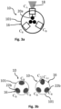
- the elongated resonating structure 16 comprises three multi-stable elements 22, equidistantly distributed around the body 101 of the micro-robot 100 (see figure 3a ).
- Each multi-stable elements 22 is associated to a weight-resonator 20 having a specific proper activation frequency f A .
- This specific proper activation frequency f A being different from the proper activation frequencies f A of the other weight-resonator 20 associated to the other multi-stable elements 22.
- each multi-stable element 22 is a bi-stable pre-compressed beam 22 between 100 ⁇ m and a few mm in length, made of polymers, glass or metal such as stainless steel or alliage.
- each beam 22 connects the steering structure 18 and the weight-resonator 20.
- Each beam 22 has two extremities, and each extremity is secured to the micro-robot 100. More precisely, each beam 22 is secured in a small open cavity of the body 101 of the micro-robot 100.
- each beam 22 presents a first stable configuration C A in which it bends inwards the cavity of the micro-robot 100 and a second stable configuration C B in which it bends outwards the cavity of the micro-robot 100.
- the first stable configuration C A corresponds to the activated steering state A
- the second stable configuration C B corresponds to the non-activated steering state B.
- the pre-compressed beam 22 In its non-activated steering state B, the pre-compressed beam 22 is bent in a first direction, away from the body 101 of the micro-robot 100. In its activated steering state A, the pre-compressed beam 22 is bent in a second direction, towards the body 101 of the micro-robot 100 and thus different from the first direction.
- the steering structure 18 comprises a retractable steering foil 18 displaying an open and a retracted configuration with regards to the body 101 of the micro-robot 100 (see figure 2a ).
- the configuration of the steering foil 18 is determined by the state of the elongated resonating structure 16 of the steering system 10.
- the foils could be made of many different flexible materials such as metals such as copper or alliage metals, glass or polymers among others. Size can vary from about 100 ⁇ m to a few mm. More precisely, the non-activated steering state B of the elongated resonating structure 16 induces a retracted configuration of the retractable steering foil 18. On the other hand, the activated steering state A of the elongated resonating structure 16 induces an open configuration of the retractable steering foil 18.
- each weight-resonator 20 comprises a resonating mass connected to the beam 22.
- This mass can be of any suitable shape, for example a bead or a cube.
- the resonating mass could also be embedded in the beam 22 by extra thickness or an extension of the shape of the beam 22.
- the activation of the resonating mass of the weight-resonator 20 thus induces a configuration change in the beam 22.
- the configuration change of the beam 22a further induces a configuration change of the corresponding steering foil 18.
- the multi-stable shell 22 displays a non-activated steering state B, in this state none of the shells oppose a resistance to the movement of the system by blocking the flow of the liquid, and several activated steering states A 1 , A 2 .
- Each activated steering state A 1 , A 2 is associated to a different proper activation resonance frequency f 1 , f 2 .
- a shell is positioned in a way that oppose the flow, this creates an asymmetry and induces a rotation in the direction to which the shell is exposed.
- the steering system 10, and more particularly the elongated resonating structure 16 comprises at least one mobile cilium 24.
- the elongated resonating structure 16 comprises at least one, preferably a group of mobile cilia 24.
- This at least one mobile cilium 24 can be part of the series of external pilis or cilia 15 which enable the micro-robot 100 to be put in motion inside the fluidic environment (see paragraph [009]).
- the at least one mobile cilium 24 may also be an independent technical element from said series of external pilis or cilia 15.
- the at least one cilium 24 is part of the steering structure 18.
- the steering structure further is configured to enable a preferential activation of one single cilium 24 over the other cilia 24.
- the steering structure may comprise a foil carried by said at least one cilium 24. The foil can present different orientations depending on the configuration and/or position of the at least one cilium 24. Those different configurations/positions enable the steering structure 18 to control the propulsion direction of the micro-robot 100.
- Each cilium 24 is secured to the body 101 of the micro-robot 100, preferably on the head portion of the micro-robot 100. More precisely, each 24 is secured to a mobile part 102 of the body 101 of the micro-robot 100. This mobile part 102 is connected to the propulsion spring 14 of the vibrating motor 12 and moves in accordance with said propulsion spring 14. Depending on the movements of the propulsion spring 14, said mobile part 102 can be centred or off-centred around the the propulsion direction X. Each cilium 24 is thus configured to be put in motion by the vibration of the micro-robot 100, more particularly by the movement of the propulsion spring 14 of the motor (actuator) 12.
- the propulsion string 14 comprises several strands 140 from which some are equipped weight-resonators 20 (see figure 5b ).
- the elongated resonating structure 16 comprises at least one strand 140 of the propulsion spring 14 of the vibrating motor/actuator 12.
- each strand 140 carrying a weight-resonator 20 is part of the multi-stable element 22 of the steering system 10.
- Each weight-resonator 20 is, similarly to the precedingly detailed embodiments, activable over a proper activation resonance frequency f A , f A1 , f A2 and deactivated under a given deactivation frequency f B .
- the propulsion spring 14 comprises three independent strands 140 and each strand 140 carries a weight-resonator 20 which is activable over a different proper activation frequency f A , f A1 , f A2 .
- the different weight-resonator 20 present different sizes and shapes, leading to different proper activation frequencies f A , f A1 , f A2 .
- the different proper activation frequencies f A , f A1 , f A2 could be dedicated to, for example, the control the shape of the weight-resonator 20.
- each strand 140 presents a first stable configuration C A in which it presents a first length L A corresponding to an activated steering state A 1 , A 2 and a second stable configuration C B in which it presents a second length L B , corresponding to the non-activated steering state B.
- the strand 140 is in its second stable configuration C B , its length L B is the same than the length of the other strands 140.
- the mobile part 102 of the body 101 of the micro-robot 100 is centred with regards to an elongation axis X of the micro-robot 100.
- Said elongation axis X is the same as the propulsion axis X already mentioned previously.
- the strand 140 When the strand 140 is in its activated configuration C A , its length changes and the mobile part 102 of the body 101 of the micro-robot 100 is off-centred.
- the activation of the elongated resonating structure 16 in one of its activated steering states A 1 , A 2 thus induces a break in the global symmetry of the body 101 of the micro-robot 100.
- each strand 140 depends on the activation/inactivation of each associated weight -resonator 20.
- the length of each strand 140 thus depends on the vibration amplitude of the vibrating motor 12 and of the propulsion spring 14, going from about 0 (it does not move) to an amplitude in hundreds of ⁇ m.
- the at least one cilium 24 is also part of the elongated resonating structure 16. However, it is also part of the steering structure 18 and of the multi-stable element 22. As in the previous embodiment, each cilium 24 carries a foil in order to enable some steering of the micro-robot 100.
- the weight-resonator 20 activable by the frequencies of the propulsion spring 14, are carried by the cilia 24. More particularly, each cilium 24 carries a weight-resonator 20 activable at a propre activation frequency f A , f A1 , f A2 .
- the at least one cilium 24 presents at least two stable states C A , C B , each stable state C A , C B being associated to a movement intensity.
- each cilium 24 presents a first stable state C B correspondent to a first movement intensity I B .
- This first stable state C B corresponds to the non-activated state of the weight-resonator 20 carried by the cilium 24 and thus corresponds to the non-activated steering state B.
- the second stable state C A corresponds to a second movement intensity I A and thus to the activated steering state A.
- the second movement intensity I A being higher than the first movement intensity I B .
- All cilium 24 in the first stable state C B are moving (back and forth movements) with the same first movement intensity I B .
- cilium (cilia) 24 Once one (or several) cilium (cilia) 24 is (are) activated, it (they) start(s) moving with a different intensity, the second movement intensity I A , thus inducing a break in the general symmetry of the micro-robot 100 which leads to a disequilibrium and eventually to a direction change.
- the activation of the weight-resonator 20 induces the elongated resonating structure 16 to enter its at least one activated steering state A, A 1 , A 2 .
- the deactivation of the weight-resonator 20 induces the elongated resonating structure 16 to enter its non-activated steering state B.
- the propulsion direction of the micro-robot 100 is maintained the same and the micro-robot 100 moves straight forward along the propulsion axis X.
- the micro-robot 100 rotates and changes its propulsion direction.
- the vibration of the propulsion spring 14 induces the micro-robot 100 to vibrate at given frequencies.
- the micro-robot 100 vibrates at the proper activation resonance frequency f A of one of the weight-resonators 20 of the elongated resonating structure 16, the considered weight-resonator 20 starts vibrating.
- This vibration induces a configuration change in its associated pre-compressed beam 22a from its inactivated configuration C B to its activated configuration C A .
- This configuration change leads the associated steering foil 18 to be expanded.
- the elongated resonating structure 16 finds itself in its steering activated state A.
- the expansion of the steering foil 18 induces a rotation of the micro-robot 100 and a redefinition of the propulsion direction X (see figure 6 ).
- the vibration of the micro-robot 100 falls below the given deactivation frequency f B of the weight-resonator 20, the weight-resonator 20 is deactivated and the pre-compressed beam 22 falls back into its inactivated configuration C B .
- the steering foil 18 is thus retracted and the elongated resonating structure 16 falls back in its inactivated steering state B.
- the frequency and/or amplitude of the motor 12 is changed to go from one resonant frequency related to a specific state to another related to another state.
- the functioning is similar to the precedent embodiment, with exception that the vibrating of the propulsion spring 14 activates directly the multi-stable shell 22b, which changes configuration and induces the micro-robot 100 to rotate.
- each cilium 24 vibrates at a given intensity, said vibration being induced by the vibrations of the vibrating motor (actuator) 12 of the micro-robot 100.
- the micro-robot 100 vibrates at the proper activation resonance frequency f A of one of the weight-resonators 20 of the elongated resonating structure 16, the considered weight-resonator 20 starts vibrating.
- This vibration induces a configuration change in its associated strand 140, more precisely a modification of its length from its second length L B defining its inactivated state C B , to its first length L A defining its activated state C A .
- This change in length induces a break in the global symmetry of the body 101 of the micro-robot 100 and the at least one cilium 24 undergoes a shift in its vibration axis, thus inducing a rotation of the micro-robot 100 (see figure 6 ).
- the activated cilium 24 thus vibrates at a different speed and a different amplitude from the other cilia 24 (or the series of external pilis or cilia 15) and this induces a rotation of the micro-robot 100 (see figure 7 ).
- This rotation of the micro-robot 100 most likely happen by a succession of jolts, creating a discrete cumulation of several small rotational movements leading to the desired final rotation. This enables an additional layer of precision and security.
Landscapes
- Health & Medical Sciences (AREA)
- Surgery (AREA)
- Engineering & Computer Science (AREA)
- Life Sciences & Earth Sciences (AREA)
- Medical Informatics (AREA)
- Robotics (AREA)
- Biomedical Technology (AREA)
- Heart & Thoracic Surgery (AREA)
- Nuclear Medicine, Radiotherapy & Molecular Imaging (AREA)
- Molecular Biology (AREA)
- Animal Behavior & Ethology (AREA)
- General Health & Medical Sciences (AREA)
- Public Health (AREA)
- Veterinary Medicine (AREA)
- Control Of Position, Course, Altitude, Or Attitude Of Moving Bodies (AREA)
- Toys (AREA)
- Micromachines (AREA)
Abstract
Description
- The present invention relates to a steering system of a micro-robot aimed at circulating through a viscous environment, in particular inside a human body.
- The ability to reach deep and functional structures without damage is a major challenge in mini-invasive surgery, especially in neurosurgery. Thanks to microtechnologies, it becomes possible to send a fully autonomous microrobot inside an organ of a subject, such as a brain. However, the propulsion of a microrobot in an environment at low Reynolds number, as in the brain, is a challenge because of absence of inertia and presence of relatively high drag forces due to the small size of the microrobot. Another important requirement is that the microrobot should be capable of moving in an organ while limiting as much as possible the physiological damage that its passage causes to the organ.
- In this context, the invention is intended to propose a microrobot having a highly efficient propulsion mechanism in a viscous environment at low Reynolds number, while preserving as much as possible the integrity of the environment in which it is displaced.
- This invention thus relates to a micro-robot configured to move along a propulsion direction by vibrations, said micro-robot comprising a body configured to vibrate, and an actuator configured to generate vibrations causing the micro-robot to move, said micro-robot further comprising a steering system which comprises a resonating structure configured to be secured to the micro-robot, the resonating structure comprising:
- a steering structure aimed at controlling the propulsion direction,
- a distribution of weight-resonators, each weight-resonator being configured to be activated by a proper activation resonance frequency, the respective proper activation resonance frequencies of the weight-resonators being different from each other,
- at least one activated steering state, in which at least one of the weight-resonators is activated at the proper activation resonance frequency to change the propulsion direction of the micro-robot,
- a non-activated steering state, in which none of the weight-resonators is activated at its proper activation resonance frequency so as to maintain the propulsion direction of the micro-robot.
- Thus, this solution achieves the above objective. In particular, it allows the obtaining of a rotation of the micro-robot solely based on the movements (energy) generated by the micro-robot itself (more precisely by the micro-motor of the micro-robot), thus avoiding the addition of extra-energy which might lead to further elements or devices to be added inside the patient or additional energy to be conveyed to the micro-robot, all which might lead to increase risks of damaging the environment in which the micro-robot moves.
- The device according to the invention may include one or more of the following characteristics, taken in isolation from one another or in combination with one another:
- the resonating structure may display several activated steering states, each activated steering state being associated to a different proper activation resonance frequency,
- o the at least one activated steering state, is a state in which the configuration and movement of the resonating structure aim at changing the propulsion direction of the micro-robot,
- o the non-activated steering state, is a state in which the configuration and movement of the resonating structure aim at maintaining the propulsion direction of the micro-robot,
- the resonating structure may further comprise a distribution of multi-stable elements, each multi-stable element being deformable between at least two stable configurations:
- at least a first stable configuration when the resonating structure is in its activated steering state,
- at least a second stable configuration when the resonating structure is in its non-activated steering state,
- the multi-stable element may be a bi-stable pre-compressed beam displaying the first and the second stable configurations, the pre-compressed beam being bent in a first direction towards the body of the micro-robot in the first stable configuration and being bent in a second direction away from the body of the micro-robot in the second stable configuration,
- the steering structure may be a retractable steering foil displaying an open and a retracted configuration with regards to the body of the micro-robot, the steering foil configuration being determined by the steering state of the resonating structure:
- the non-activated steering state of the resonating structure induces the retracted configuration of the retractable steering foil, and
- the activated steering state of the resonating structure induces the open configuration of the retractable steering foil,
- each multi-stable element may be a multi-stable shell comprising a stack of several sheets,
- the steering system may further comprise at least one mobile cilium, the at least one cilium being configured to be put in motion by the vibration of the body of the micro-robot,
- the resonating structure may comprise at least one strand of a propulsion spring comprised within the body,
- the activation of the resonating structure in its at least one activated steering state may induce the retractation of the at least one strand of the propulsion spring,
- the body of the micro-robot may present a global circular symmetry along a propulsion axis parallel to the propulsion direction, wherein the resonating structure is further part of said body, and wherein the activation of the resonating structure into one of its activated steering states induces a break in the global circular symmetry of the body,
- the at least one cilium may be part of the resonating structure, the at least one cilium presenting a first movement intensity in the non-activated steering state and a second movement intensity in the activated steering state, the second movement intensity being different than the first movement intensity,
- each cilium may comprise a weight-resonator.
- The invention will be better understood, and other aims, details, characteristics and advantages thereof will emerge more clearly on reading the detailed explanatory description which follows, of embodiments of the invention given by way of illustration. purely illustrative and non-limiting examples, with reference to the accompanying drawings.
-
figure 1a is a general schematic side view of the micro robot comprising a steering system according to a first embodiment of the present invention, -
figure 1b is a general schematic side view of the micro robot comprising a steering system according to a second embodiment of the present invention, -
figure 2a is a detailed schematic side view of the steering system according to the first embodiment of the present invention, -
figure 2b is a detailed schematic side view of the steering system according to the second embodiment of the present invention, -
figure 3a is a detailed schematic view from above of the steering system according to the first embodiment of the present invention, -
figure 3b is a detailed schematic view from above of the steering system according to the second embodiment of the present invention, -
figure 4 is a step-by-step schematic view of the activation of the steering system according to the first embodiment, -
figure 5a is a general schematic side view of the micro robot comprising a steering system according to a third embodiment of the present invention, -
figure 5b is a detailed schematic side view of the steering system according to the third embodiment of the present invention, -
figure 5c is a detailed schematic view from above of the steering system according to the third embodiment of the present invention, -
figure 6 is a step-by-step schematic view of the activation of the steering system according to the third embodiment of the present invention, -
figure 7a is a general schematic side view of the micro robot comprising a steering system according to a fourth embodiment of the present invention, -
figure 7b is a detailed schematic side view of the steering system according to the fourth embodiment of the present invention, -
figure 7c is a detailed schematic view from above of the steering system according to the fourth embodiment of the present invention, -
figure 8 is a step-by-step schematic view of the activation of the steering system according to the fourth embodiment of the present invention. - Please note that in the present application, the term "weight-resonator" is given a wide definition: It is not necessarily just resonators based on their weight. They might also include foils and bi-stable or multi-stable elements which enable to play with the shape of the part and the internal tensions that generate several stable states. Those enable to go from one stable state to another by bringing energy. This is achieved, as will be explained further below in detail, by the change of a resonance frequency which maximizes the available/conducted energy.
- As can be seen on
figures 1a and 1b , thesteering system 10 according to the present invention, is aimed at being part of a micro-robot 100 configured to move inside a fluidic environment, more precisely along a propulsion direction following a propulsion axis X. This movement along the propulsion direction happens by vibration inside the fluidic environment. - The micro-robot 100 thus comprises a
body 101 comprising anactuator 12 configured to generate vibrations. More precisely, in the represented embodiments, theactuator 12 is avibrating motor 12 which comprises acoil 120 and amagnet 121. Thecoil 120 extends along the propulsion direction X and surrounds themagnet 121. Themagnet 121 is activable by thecoil 120 and is configured to move back and forth along the propulsion direction X. The movement of themagnet 121 induces a compression/decompression movement of apropulsion spring 14 also part of the vibratingmotor 12 and also extending along the propulsion direction X.Said propulsion spring 14 allows the movement of a series of external pilis orcilia 15 which enable the micro-robot 100 to be put in motion inside the fluidic environment. - Many fluidic environments can be targeted, but specifically all bodily fluids are concerned. Those bodily fluid are, for example, blood, cerebra spinal fluids, urine, bile liquid, lymph fluid, aqueous humor. Those fluids all present a viscosity close to that of water.
- As can be further seen on
figures 1a and 1b , thesteering system 10 according to the present invention comprises anelongated resonating structure 16 aimed at being secured to themicro-robot 100. - This elongated resonating
structure 16 comprises: - a
steering structure 18 aimed at controlling the propulsion direction, - a distribution of weight-
resonators 20 configured to be activated over a proper (or given) activation resonance frequency fA, fA1, fA2 and deactivated under a proper (or given) deactivation frequency fB. - The respective proper activation resonance frequencies fA, fA1, fA2 of each weight-
resonator 20 is different from the proper activation resonance frequencies fA, fA1, fA2 of the other weight-resonators 20. Theactuator 12 is configured to generate vibrations in a range of frequencies including the proper activation resonance frequency fA, fA1, fA2 of each weight-resonator 20.Theelongated resonating structure 16 displays at least two states: - at least one activated steering state A, A1, A2, in which the configuration and movement of the
elongated resonating structure 16 are configured to change the propulsion direction of the micro-robot 100, - a non-activated steering state B, in which the configuration and movement of the
elongated resonating structure 16 are configured to maintain the propulsion direction of themicro-robot 100. - Regardless of the embodiment, the state B, A, A1, A2 of the
elongated resonating structure 16, is determined by the activation or deactivation of the weight-resonators 20 as will be explained further below. - As will be explained further below, the activation and deactivation frequencies fB, fA, fA1, fA2 of the weight-
resonator 20 are induced by the vibrations of the micro-robot body 101 (mor particularly the vibrations induced by the micro-motor comprised within thebody 101 of the micro-robot) when the micro-robot 100 is moving along its propulsion direction. - More particularly regarding
figures 1a and 1b , theelongated resonating structure 16 further comprises a distribution ofmulti-stable element 22 secured to themicro-robot 100. Eachmulti-stable element 22 displays at least two stable configurations and is deformable between those at least two stable configurations: - at least a first stable configuration CA, CA1, CA2 when the resonating
structure 16 is in its activated steering state A, A1, A2 (seefigures 2a, 2b ), - at least a second stable configuration CB when the resonating
structure 16 is in its non-activated steering state B (seefigures 2a, 2b ). - Depending on the embodiments, the
multi-stable element 22, the weight-resonator 20 and thesteering structure 18 can be the same technical element or distinct elements. For example, in the embodiment depicted onfigure 1a , themulti-stable element 22, theweight resonator 20 and thesteering structure 18 are all distinct technical elements. However, regarding the embodiment depicted onfigure 1b , themulti-stable element 22, the weight-resonator 20 and thesteering structure 18 are the same technical element. In this case, the different proper activation frequencies fA, fA1, fA2 could be dedicated to, for example, the control the shape of the weight-resonator 20 (or multi-stable element 22). One could have a frequency for semi-closure, another for full closure, for example. - More precisely regarding the embodiment depicted on
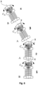
figures 1a ,2a and3a , theelongated resonating structure 16 comprises threemulti-stable elements 22, equidistantly distributed around thebody 101 of the micro-robot 100 (seefigure 3a ). Eachmulti-stable elements 22 is associated to a weight-resonator 20 having a specific proper activation frequency fA. This specific proper activation frequency fA being different from the proper activation frequencies fA of the other weight-resonator 20 associated to the othermulti-stable elements 22. In this example, eachmulti-stable element 22 is a bi-stablepre-compressed beam 22 between 100µm and a few mm in length, made of polymers, glass or metal such as stainless steel or alliage. In this particular embodiment, eachbeam 22 connects thesteering structure 18 and the weight-resonator 20. Eachbeam 22 has two extremities, and each extremity is secured to themicro-robot 100. More precisely, eachbeam 22 is secured in a small open cavity of thebody 101 of themicro-robot 100. As already mentioned, eachbeam 22 presents a first stable configuration CA in which it bends inwards the cavity of the micro-robot 100 and a second stable configuration CB in which it bends outwards the cavity of themicro-robot 100. The first stable configuration CA corresponds to the activated steering state A, the second stable configuration CB corresponds to the non-activated steering state B. In its non-activated steering state B, thepre-compressed beam 22 is bent in a first direction, away from thebody 101 of themicro-robot 100. In its activated steering state A, thepre-compressed beam 22 is bent in a second direction, towards thebody 101 of the micro-robot 100 and thus different from the first direction. - Still considering the embodiment on
figures 1a and2a , thesteering structure 18 comprises aretractable steering foil 18 displaying an open and a retracted configuration with regards to thebody 101 of the micro-robot 100 (seefigure 2a ). As will be explained later, the configuration of thesteering foil 18 is determined by the state of theelongated resonating structure 16 of thesteering system 10. The foils could be made of many different flexible materials such as metals such as copper or alliage metals, glass or polymers among others. Size can vary from about 100µm to a few mm. More precisely, the non-activated steering state B of theelongated resonating structure 16 induces a retracted configuration of theretractable steering foil 18. On the other hand, the activated steering state A of theelongated resonating structure 16 induces an open configuration of theretractable steering foil 18. - Still considering
figure 1a , each weight-resonator 20 comprises a resonating mass connected to thebeam 22. This mass can be of any suitable shape, for example a bead or a cube. Depending on the embodiment the resonating mass could also be embedded in thebeam 22 by extra thickness or an extension of the shape of thebeam 22. The activation of the resonating mass of the weight-resonator 20 thus induces a configuration change in thebeam 22. The configuration change of the beam 22a further induces a configuration change of thecorresponding steering foil 18. - In the embodiment presented in
figures 1b ,2b and3b , themulti-stable element 22 is amulti-stable shell 22 comprising a stack of several sheets. The multi-stable elements could be made of many different flexible materials who have this multi-stable state capacity when shaped appropriately such as copper. Size can vary from about 100µm to a few mm. - In this embodiment, the
multi-stable shell 22 displays a non-activated steering state B, in this state none of the shells oppose a resistance to the movement of the system by blocking the flow of the liquid, and several activated steering states A1, A2. Each activated steering state A1, A2 is associated to a different proper activation resonance frequency f1, f2. In those activated states, a shell is positioned in a way that oppose the flow, this creates an asymmetry and induces a rotation in the direction to which the shell is exposed. - According to further embodiments depicted, in particular, on
figures 5a and7a , thesteering system 10, and more particularly theelongated resonating structure 16, comprises at least onemobile cilium 24. In some embodiment, theelongated resonating structure 16 comprises at least one, preferably a group ofmobile cilia 24. This at least onemobile cilium 24 can be part of the series of external pilis orcilia 15 which enable the micro-robot 100 to be put in motion inside the fluidic environment (see paragraph [009]). The at least onemobile cilium 24 may also be an independent technical element from said series of external pilis orcilia 15. - In the embodiments of
figures 5a and7a , the at least onecilium 24 is part of thesteering structure 18. In this embodiment, the steering structure further is configured to enable a preferential activation of onesingle cilium 24 over theother cilia 24. In order to achieve this, the steering structure may comprise a foil carried by said at least onecilium 24. The foil can present different orientations depending on the configuration and/or position of the at least onecilium 24. Those different configurations/positions enable thesteering structure 18 to control the propulsion direction of themicro-robot 100. - Each
cilium 24 is secured to thebody 101 of the micro-robot 100, preferably on the head portion of themicro-robot 100. More precisely, each 24 is secured to amobile part 102 of thebody 101 of themicro-robot 100. Thismobile part 102 is connected to thepropulsion spring 14 of the vibratingmotor 12 and moves in accordance with saidpropulsion spring 14. Depending on the movements of thepropulsion spring 14, saidmobile part 102 can be centred or off-centred around the the propulsion direction X. Eachcilium 24 is thus configured to be put in motion by the vibration of the micro-robot 100, more particularly by the movement of thepropulsion spring 14 of the motor (actuator) 12. - In this embodiment, the
propulsion string 14 comprisesseveral strands 140 from which some are equipped weight-resonators 20 (seefigure 5b ). Thus, in this embodiment, theelongated resonating structure 16 comprises at least onestrand 140 of thepropulsion spring 14 of the vibrating motor/actuator 12. - More particularly, in the embodiment depicted on
figures 5a ,5b ,5c and6 , eachstrand 140 carrying a weight-resonator 20 is part of themulti-stable element 22 of thesteering system 10. Each weight-resonator 20 is, similarly to the precedingly detailed embodiments, activable over a proper activation resonance frequency fA, fA1, fA2 and deactivated under a given deactivation frequency fB. As can be seen onfigure 5b , thepropulsion spring 14 comprises threeindependent strands 140 and eachstrand 140 carries a weight-resonator 20 which is activable over a different proper activation frequency fA, fA1, fA2. As hinted at infigure 5b , the different weight-resonator 20 present different sizes and shapes, leading to different proper activation frequencies fA, fA1, fA2. In an alternative embodiment, the different proper activation frequencies fA, fA1, fA2 could be dedicated to, for example, the control the shape of the weight-resonator 20. One could have a frequency for semi-closure, another for full closure. - In this embodiment (
figures 5a ,5b ,5c and6 ), the activation of theelongated resonating structure 16 in its at least one activated steering state A, A1, A2 (seefigure 6 ), and more particularly the activation of each weight-resonator 20 induces a retractation of thecorresponding strand 140 of thepropulsion spring 14. - More particularly, in this embodiment (
figures 5a ,5b ,5c and6 ), eachstrand 140 presents a first stable configuration CA in which it presents a first length LA corresponding to an activated steering state A1, A2 and a second stable configuration CB in which it presents a second length LB, corresponding to the non-activated steering state B. When thestrand 140 is in its second stable configuration CB, its length LB is the same than the length of theother strands 140. In this second stable configuration, themobile part 102 of thebody 101 of the micro-robot 100, is centred with regards to an elongation axis X of themicro-robot 100. Said elongation axis X is the same as the propulsion axis X already mentioned previously. When thestrand 140 is in its activated configuration CA, its length changes and themobile part 102 of thebody 101 of the micro-robot 100 is off-centred. The activation of theelongated resonating structure 16 in one of its activated steering states A1, A2 thus induces a break in the global symmetry of thebody 101 of themicro-robot 100. - Regarding the embodiments depicted respectively on
figures 1a ,2a ,3a and1b ,2b and3b , it can also be said that the activation of theelongated resonating structure 16 in one of its activated steering states A1, A2 induces a break in the global symmetry of thebody 101 of the micro-robot 100: the spreading of the foils 18a, 18b break the global rotational symmetry of themicro-robot 100. - The length of each
strand 140 depends on the activation/inactivation of each associated weight -resonator 20. The length of eachstrand 140 thus depends on the vibration amplitude of the vibratingmotor 12 and of thepropulsion spring 14, going from about 0 (it does not move) to an amplitude in hundreds of µm. - In the last depicted embodiment of the present invention (
figures 7a ,7b ,7c and8 ), the at least onecilium 24 is also part of theelongated resonating structure 16. However, it is also part of thesteering structure 18 and of themulti-stable element 22. As in the previous embodiment, eachcilium 24 carries a foil in order to enable some steering of themicro-robot 100. - In this embodiment, the weight-
resonator 20 activable by the frequencies of thepropulsion spring 14, are carried by thecilia 24. More particularly, eachcilium 24 carries a weight-resonator 20 activable at a propre activation frequency fA, fA1, fA2. - In this embodiment, the at least one
cilium 24 presents at least two stable states CA, CB, each stable state CA, CB being associated to a movement intensity. This way, eachcilium 24 presents a first stable state CB correspondent to a first movement intensity IB. This first stable state CB corresponds to the non-activated state of the weight-resonator 20 carried by thecilium 24 and thus corresponds to the non-activated steering state B. The second stable state CA corresponds to a second movement intensity IA and thus to the activated steering state A. The second movement intensity IA being higher than the first movement intensity IB. Allcilium 24 in the first stable state CB are moving (back and forth movements) with the same first movement intensity IB. Once one (or several) cilium (cilia) 24 is (are) activated, it (they) start(s) moving with a different intensity, the second movement intensity IA, thus inducing a break in the general symmetry of the micro-robot 100 which leads to a disequilibrium and eventually to a direction change. - As mentioned above, for each embodiment, the activation of the weight-
resonator 20 induces theelongated resonating structure 16 to enter its at least one activated steering state A, A1, A2. On the other hand, the deactivation of the weight-resonator 20 induces theelongated resonating structure 16 to enter its non-activated steering state B. - When the
elongated resonating structure 16 is in its non-activated steering state B, the propulsion direction of the micro-robot 100 is maintained the same and the micro-robot 100 moves straight forward along the propulsion axis X. However, when theelongated resonating structure 16 enters its at least one activated steering state A, A1, A2, themicro-robot 100 rotates and changes its propulsion direction. - Considering the first embodiment (
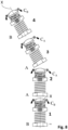
figures 1a ,2a ,3a ,4 ), the vibration of thepropulsion spring 14 induces the micro-robot 100 to vibrate at given frequencies. When the micro-robot 100 vibrates at the proper activation resonance frequency fA of one of the weight-resonators 20 of theelongated resonating structure 16, the considered weight-resonator 20 starts vibrating. This vibration induces a configuration change in its associated pre-compressed beam 22a from its inactivated configuration CB to its activated configuration CA. This configuration change leads the associatedsteering foil 18 to be expanded. Theelongated resonating structure 16 finds itself in its steering activated state A. The expansion of thesteering foil 18 induces a rotation of the micro-robot 100 and a redefinition of the propulsion direction X (seefigure 6 ). When the vibration of the micro-robot 100 falls below the given deactivation frequency fB of the weight-resonator 20, the weight-resonator 20 is deactivated and thepre-compressed beam 22 falls back into its inactivated configuration CB. Thesteering foil 18 is thus retracted and theelongated resonating structure 16 falls back in its inactivated steering state B. The frequency and/or amplitude of themotor 12 is changed to go from one resonant frequency related to a specific state to another related to another state. - Regarding the second embodiment (
figures 1b ,2b ,3b ), the functioning is similar to the precedent embodiment, with exception that the vibrating of thepropulsion spring 14 activates directly themulti-stable shell 22b, which changes configuration and induces the micro-robot 100 to rotate. - Considering the fourth embodiment (
figures 5a ,5b ,5c ,6 ), it has to be specified that eachcilium 24 vibrates at a given intensity, said vibration being induced by the vibrations of the vibrating motor (actuator) 12 of themicro-robot 100. When the micro-robot 100 vibrates at the proper activation resonance frequency fA of one of the weight-resonators 20 of theelongated resonating structure 16, the considered weight-resonator 20 starts vibrating. This vibration induces a configuration change in its associatedstrand 140, more precisely a modification of its length from its second length LB defining its inactivated state CB, to its first length LA defining its activated state CA. This change in length induces a break in the global symmetry of thebody 101 of the micro-robot 100 and the at least onecilium 24 undergoes a shift in its vibration axis, thus inducing a rotation of the micro-robot 100 (seefigure 6 ). - Regarding the last embodiment (
figures 7a ,7b ,7c and8 ), when the micro-robot 100 vibrates at the proper activation resonance frequency fA of one of the weight-resonators 20 of theelongated resonating structure 16, the considered weight-resonator 20 starts vibrating. This vibration induces a configuration change in the vibration intensity of the associatedcilium 24. Thecilium 24 then changes from its first movement intensity IB (corresponding to the steering non-activated state B of the elongated resonating structure 16) to its movement intensity IA (corresponding to the steering activated state A of the elongated resonating structure 16). The activatedcilium 24 thus vibrates at a different speed and a different amplitude from the other cilia 24 (or the series of external pilis or cilia 15) and this induces a rotation of the micro-robot 100 (seefigure 7 ). - This rotation of the micro-robot 100 most likely happen by a succession of jolts, creating a discrete cumulation of several small rotational movements leading to the desired final rotation. This enables an additional layer of precision and security.
- The fact of being able to manage the 3D orientation of a device with only one linear actuator on which a user can change the activation frequency from a distance, gives a 2D plane of solutions (one axis = frequency, one axis = intensity) and one need solely to navigate in this plane to have the desired configuration, which is both more easy and more reliable.
Claims (13)
- Micro-robot (100) configured to move along a propulsion direction by vibrations, said micro-robot (100) comprising a body (101) configured to vibrate, and an actuator (12) configured to generate vibrations causing the micro-robot (100) to move,
said micro-robot (100) further comprising a steering system (10) which comprises a resonating structure (16) configured to be secured to the micro-robot (100), the resonating structure (16) comprising:- a steering structure (18) aimed at controlling the propulsion direction,- a distribution of weight-resonators (20), each weight-resonator (20) being configured to be activated by a proper activation resonance frequency (fA, fA1, fA2), the respective proper activation resonance frequencies (fA, fA1, fA2) of the weight-resonators (20) being different from each other,wherein the actuator (12) is configured to generate vibrations in a range of frequencies including the proper activation resonance frequency of each weight-resonator,
wherein the resonating structure (16) displays at least two states:- at least one activated steering state (A, A1, A2), in which at least one of the weight-resonators is activated at the proper activation resonance frequency to change the propulsion direction of the micro-robot (100),- a non-activated steering state (B), in which none of the weight-resonators is activated at its proper activation resonance frequency so as to maintain the propulsion direction of the micro-robot (100). - Micro-robot (100) according to the preceding claim, wherein the resonating structure (16) displays several activated steering states (A1, A2), each activated steering state (A1, A2) being associated to a different proper activation resonance frequency (fA1, fA2).
- Micro-robot (100) according to any one of the preceding claims, wherein:- the at least one activated steering state (A, A1, A2), is a state in which the configuration and movement of the resonating structure (16) aim at changing the propulsion direction of the micro-robot (100),- the non-activated steering state (B), is a state in which the configuration and movement of the resonating structure (16) aim at maintaining the propulsion direction of the micro-robot (100),
- Micro-robot (100) according to any one of the preceding claims, wherein the resonating structure (16) further comprises a distribution of multi-stable elements (22), each multi-stable element (22) being deformable between at least two stable configurations:- at least a first stable configuration (CA) when the resonating structure (16) is in its activated steering state (A),- at least a second stable configuration (CB) when the resonating structure (16) is in its non-activated steering state (B).
- Micro-robot (100) according to the preceding claim, wherein each multi-stable element (22) is a bi-stable pre-compressed beam (22) displaying the first and the second stable configurations (CA, CB), the pre-compressed beam (22) being bent in a first direction towards the body (101) of the micro-robot (100) in the first stable configuration (CA) and being bent in a second direction away from the body (101) of the micro-robot (100) in the second stable configuration (CB).
- Micro-robot (100) according to any one of the preceding claims, wherein the steering structure (18) is a retractable steering foil (18) displaying an open and a retracted configuration with regards to the body (101) of the micro-robot (100), the steering foil (18) configuration being determined by the steering state (A, A1, A2, B) of the resonating structure (16):- the non-activated steering state (B) of the resonating structure (16) induces the retracted configuration of the retractable steering foil (18), and- the activated steering state (A, A1, A2) of the resonating structure (16) induces the open configuration of the retractable steering foil (18).
- Micro-robot (100) according to claim 4, wherein each multi-stable element (22) is a multi-stable shell (22) comprising a stack of several sheets.
- Micro-robot (100) according to anyone of the preceding claims, wherein the steering system (10) further comprises at least one mobile cilium (24), the at least one cilium (24) being configured to be put in motion by the vibration of the body (101) of the micro-robot (100).
- Micro-robot (100) according to the precedent claim, wherein the resonating structure (16) comprises at least one strand of a propulsion spring (14) comprised within the body (101).
- Micro-robot (100) according to the precedent claim, wherein the activation of the resonating structure (16) in its at least one activated steering state (A, A1, A2) induces the retractation of the at least one strand of the propulsion spring (14).
- Micro-robot (100) according to claims 9 or 10, wherein the body (101) of the micro-robot (10) presents a global circular symmetry along a propulsion axis parallel to the propulsion direction, wherein the resonating structure (16) is further part of said body (101), and wherein the activation of the resonating structure (16) into one of its activated steering states (A, A1, A2) induces a break in the global circular symmetry of the body (101).
- Micro-robot (100) according to claim 8, wherein the at least one cilium (24) is part of the resonating structure (16), the at least one cilium (24) presenting a first movement intensity (IB) in the non-activated steering state (B) and a second movement intensity (IA) in the activated steering state (A, A1, A2), the second movement intensity (IA) being different than the first movement intensity (IB).
- Micro-robot (100) according to the preceding claim, wherein each cilium (24) comprises a weight-resonator (20).
Priority Applications (5)
| Application Number | Priority Date | Filing Date | Title |
|---|---|---|---|
| EP22306833.9A EP4382070B1 (en) | 2022-12-09 | 2022-12-09 | Resonating system - limp |
| ES22306833T ES3045710T3 (en) | 2022-12-09 | 2022-12-09 | Resonating system - limp |
| PL22306833.9T PL4382070T3 (en) | 2022-12-09 | 2022-12-09 | Resonating system - limp |
| CN202380084642.1A CN120435262A (en) | 2022-12-09 | 2023-12-06 | Resonance System—LIMP |
| PCT/EP2023/084614 WO2024121268A1 (en) | 2022-12-09 | 2023-12-06 | Resonating system – the limp |
Applications Claiming Priority (1)
| Application Number | Priority Date | Filing Date | Title |
|---|---|---|---|
| EP22306833.9A EP4382070B1 (en) | 2022-12-09 | 2022-12-09 | Resonating system - limp |
Publications (2)
| Publication Number | Publication Date |
|---|---|
| EP4382070A1 true EP4382070A1 (en) | 2024-06-12 |
| EP4382070B1 EP4382070B1 (en) | 2025-07-16 |
Family
ID=84785283
Family Applications (1)
| Application Number | Title | Priority Date | Filing Date |
|---|---|---|---|
| EP22306833.9A Active EP4382070B1 (en) | 2022-12-09 | 2022-12-09 | Resonating system - limp |
Country Status (5)
| Country | Link |
|---|---|
| EP (1) | EP4382070B1 (en) |
| CN (1) | CN120435262A (en) |
| ES (1) | ES3045710T3 (en) |
| PL (1) | PL4382070T3 (en) |
| WO (1) | WO2024121268A1 (en) |
Citations (3)
| Publication number | Priority date | Publication date | Assignee | Title |
|---|---|---|---|---|
| US20100264776A1 (en) * | 2007-07-02 | 2010-10-21 | Eth Zurich | Wireless resonant magnetic acutation for untethered microrobots |
| US20200305796A1 (en) * | 2019-03-29 | 2020-10-01 | Robeaute | Microrobot configured to move in a viscous material |
| US20220273383A1 (en) * | 2019-09-20 | 2022-09-01 | Robeaute | Device for propelling and steering a microstructure |
-
2022
- 2022-12-09 EP EP22306833.9A patent/EP4382070B1/en active Active
- 2022-12-09 PL PL22306833.9T patent/PL4382070T3/en unknown
- 2022-12-09 ES ES22306833T patent/ES3045710T3/en active Active
-
2023
- 2023-12-06 CN CN202380084642.1A patent/CN120435262A/en active Pending
- 2023-12-06 WO PCT/EP2023/084614 patent/WO2024121268A1/en not_active Ceased
Patent Citations (3)
| Publication number | Priority date | Publication date | Assignee | Title |
|---|---|---|---|---|
| US20100264776A1 (en) * | 2007-07-02 | 2010-10-21 | Eth Zurich | Wireless resonant magnetic acutation for untethered microrobots |
| US20200305796A1 (en) * | 2019-03-29 | 2020-10-01 | Robeaute | Microrobot configured to move in a viscous material |
| US20220273383A1 (en) * | 2019-09-20 | 2022-09-01 | Robeaute | Device for propelling and steering a microstructure |
Non-Patent Citations (5)
| Title |
|---|
| DEASUNG JANG ET AL: "Targeted drug delivery technology using untethered microrobots: a review", JOURNAL OF MICROMECHANICS AND MICROENGINEERING, INSTITUTE OF PHYSICS PUBLISHING, BRISTOL, GB, vol. 29, no. 5, 20 March 2019 (2019-03-20), pages 53002, XP020336337, ISSN: 0960-1317, [retrieved on 20190320], DOI: 10.1088/1361-6439/AB087D * |
| MOHAND-OUSAID ABDENBI ET AL: "Compact Digital Microrobot Based on Multistable Modules", IEEE ROBOTICS AND AUTOMATION LETTERS, IEEE, vol. 6, no. 2, 22 February 2021 (2021-02-22), pages 1926 - 1933, XP011841082, DOI: 10.1109/LRA.2021.3061003 * |
| QIAO CHEN ET AL: "Microfabricated Bistable Module for Digital Microrobotics", vol. 6, no. 1-2, 21 January 2011 (2011-01-21), pages 1 - 12, XP002660690, ISSN: 1865-3928, Retrieved from the Internet <URL:http://hal.archives-ouvertes.fr/docs/00/55/84/15/PDF/JMNM2010_Yassine.pdf> [retrieved on 20111006], DOI: 10.1007/S12213-010-0025-2 * |
| QINXUE PAN ET AL: "Paddling type of microrobot in pipe", 2009 IEEE INTERNATIONAL CONFERENCE ON ROBOTICS AND AUTOMATION : (ICRA) ; KOBE, JAPAN, 12 - 17 MAY 2009, IEEE, PISCATAWAY, NJ, USA, 12 May 2009 (2009-05-12), pages 2995 - 3000, XP031483242, ISBN: 978-1-4244-2788-8 * |
| YANG LIDONG ET AL: "A Miniature Flexible-Link Magnetic Swimming Robot With Two Vibration Modes: Design, Modeling and Characterization", IEEE ROBOTICS AND AUTOMATION LETTERS, IEEE, vol. 2, no. 4, 1 October 2017 (2017-10-01), pages 2024 - 2031, XP011655623, DOI: 10.1109/LRA.2017.2718104 * |
Also Published As
| Publication number | Publication date |
|---|---|
| WO2024121268A1 (en) | 2024-06-13 |
| EP4382070B1 (en) | 2025-07-16 |
| PL4382070T3 (en) | 2025-11-12 |
| ES3045710T3 (en) | 2025-11-28 |
| CN120435262A (en) | 2025-08-05 |
Similar Documents
| Publication | Publication Date | Title |
|---|---|---|
| TWI700240B (en) | Micromechanical component and method for adjusting an adjustable part simultaneously about two axes of rotation inclined in relation to one another | |
| US8551041B2 (en) | Navigable system for catheter based endovascular neurosurgery | |
| EP4134991B1 (en) | Magnetic tube system | |
| CN108135659A (en) | For the touch feedback control device of robotic surgical system interface | |
| Suzuki et al. | Development of a new type piezoelectric micromotor | |
| EP4382070B1 (en) | Resonating system - limp | |
| US20110215888A1 (en) | Wireless control of microrobots | |
| WO2012131682A1 (en) | Compliant structures with time-varying moment of inertia | |
| US11191886B2 (en) | Motion-assisted systems, devices and methods for minimizing obstruction of medical devices | |
| EP4023175B1 (en) | Microrobot and microrobot system including same | |
| Kim et al. | A pushing force mechanism of magnetic spiral-type machine for wireless medical-robots in therapy and diagnosis | |
| WO2015123361A1 (en) | Complex mass trajectories for improved haptic effect | |
| KR101462588B1 (en) | Micro-robot for motion in tubular shape | |
| US12203467B2 (en) | Pump system and electronics device | |
| JP3860077B2 (en) | Alarm system and alarm clock | |
| CN114652452A (en) | From the operating end arm | |
| Ikuta et al. | Two-lead-wire drive for multi-micro actuators [medical micro robots] | |
| JP2003166554A (en) | Driving shaft of rotary device | |
| CN111657829A (en) | Device and method for magnetically controlling movement of capsule endoscope in human body | |
| Nelson | Towards nanorobots | |
| JP2025502071A (en) | Magnetic Microrobot | |
| KR102910376B1 (en) | Magnetic prefabricated ultra compact medical robot with multiple module structures | |
| JP2006212220A (en) | Micro machine | |
| Lai et al. | Design of drug-delivery micro-wheel and auto-rolling control by change of gravity center | |
| JP2011095490A (en) | Optical device |
Legal Events
| Date | Code | Title | Description |
|---|---|---|---|
| PUAI | Public reference made under article 153(3) epc to a published international application that has entered the european phase |
Free format text: ORIGINAL CODE: 0009012 |
|
| STAA | Information on the status of an ep patent application or granted ep patent |
Free format text: STATUS: THE APPLICATION HAS BEEN PUBLISHED |
|
| AK | Designated contracting states |
Kind code of ref document: A1 Designated state(s): AL AT BE BG CH CY CZ DE DK EE ES FI FR GB GR HR HU IE IS IT LI LT LU LV MC ME MK MT NL NO PL PT RO RS SE SI SK SM TR |
|
| STAA | Information on the status of an ep patent application or granted ep patent |
Free format text: STATUS: REQUEST FOR EXAMINATION WAS MADE |
|
| 17P | Request for examination filed |
Effective date: 20241212 |
|
| GRAP | Despatch of communication of intention to grant a patent |
Free format text: ORIGINAL CODE: EPIDOSNIGR1 |
|
| STAA | Information on the status of an ep patent application or granted ep patent |
Free format text: STATUS: GRANT OF PATENT IS INTENDED |
|
| INTG | Intention to grant announced |
Effective date: 20250203 |
|
| GRAS | Grant fee paid |
Free format text: ORIGINAL CODE: EPIDOSNIGR3 |
|
| GRAA | (expected) grant |
Free format text: ORIGINAL CODE: 0009210 |
|
| STAA | Information on the status of an ep patent application or granted ep patent |
Free format text: STATUS: THE PATENT HAS BEEN GRANTED |
|
| AK | Designated contracting states |
Kind code of ref document: B1 Designated state(s): AL AT BE BG CH CY CZ DE DK EE ES FI FR GB GR HR HU IE IS IT LI LT LU LV MC ME MK MT NL NO PL PT RO RS SE SI SK SM TR |
|
| RAP3 | Party data changed (applicant data changed or rights of an application transferred) |
Owner name: ROBEAUTE |
|
| REG | Reference to a national code |
Ref country code: GB Ref legal event code: FG4D |
|
| REG | Reference to a national code |
Ref country code: CH Ref legal event code: EP |
|
| REG | Reference to a national code |
Ref country code: DE Ref legal event code: R096 Ref document number: 602022017639 Country of ref document: DE |
|
| REG | Reference to a national code |
Ref country code: IE Ref legal event code: FG4D |
|
| P01 | Opt-out of the competence of the unified patent court (upc) registered |
Free format text: CASE NUMBER: UPC_APP_3063_4382070/2025 Effective date: 20250811 |
|
| REG | Reference to a national code |
Ref country code: CH Ref legal event code: R17 Free format text: ST27 STATUS EVENT CODE: U-0-0-R10-R17 (AS PROVIDED BY THE NATIONAL OFFICE) Effective date: 20251006 |
|
| REG | Reference to a national code |
Ref country code: SE Ref legal event code: TRGR |
|
| REG | Reference to a national code |
Ref country code: NL Ref legal event code: FP |
|
| REG | Reference to a national code |
Ref country code: ES Ref legal event code: FG2A Ref document number: 3045710 Country of ref document: ES Kind code of ref document: T3 Effective date: 20251128 |
|
| PG25 | Lapsed in a contracting state [announced via postgrant information from national office to epo] |
Ref country code: PT Free format text: LAPSE BECAUSE OF FAILURE TO SUBMIT A TRANSLATION OF THE DESCRIPTION OR TO PAY THE FEE WITHIN THE PRESCRIBED TIME-LIMIT Effective date: 20251117 |
|
| REG | Reference to a national code |
Ref country code: CH Ref legal event code: U11 Free format text: ST27 STATUS EVENT CODE: U-0-0-U10-U11 (AS PROVIDED BY THE NATIONAL OFFICE) Effective date: 20260101 |
|
| PG25 | Lapsed in a contracting state [announced via postgrant information from national office to epo] |
Ref country code: IS Free format text: LAPSE BECAUSE OF FAILURE TO SUBMIT A TRANSLATION OF THE DESCRIPTION OR TO PAY THE FEE WITHIN THE PRESCRIBED TIME-LIMIT Effective date: 20251116 |
|
| PGFP | Annual fee paid to national office [announced via postgrant information from national office to epo] |
Ref country code: DE Payment date: 20251211 Year of fee payment: 4 |
|
| PG25 | Lapsed in a contracting state [announced via postgrant information from national office to epo] |
Ref country code: NO Free format text: LAPSE BECAUSE OF FAILURE TO SUBMIT A TRANSLATION OF THE DESCRIPTION OR TO PAY THE FEE WITHIN THE PRESCRIBED TIME-LIMIT Effective date: 20251016 |
|
| REG | Reference to a national code |
Ref country code: LT Ref legal event code: MG9D |
|
| PGFP | Annual fee paid to national office [announced via postgrant information from national office to epo] |
Ref country code: AT Payment date: 20260113 Year of fee payment: 4 |
|
| PG25 | Lapsed in a contracting state [announced via postgrant information from national office to epo] |
Ref country code: FI Free format text: LAPSE BECAUSE OF FAILURE TO SUBMIT A TRANSLATION OF THE DESCRIPTION OR TO PAY THE FEE WITHIN THE PRESCRIBED TIME-LIMIT Effective date: 20250716 |
|
| PG25 | Lapsed in a contracting state [announced via postgrant information from national office to epo] |
Ref country code: HR Free format text: LAPSE BECAUSE OF FAILURE TO SUBMIT A TRANSLATION OF THE DESCRIPTION OR TO PAY THE FEE WITHIN THE PRESCRIBED TIME-LIMIT Effective date: 20250716 |
|
| PGFP | Annual fee paid to national office [announced via postgrant information from national office to epo] |
Ref country code: FR Payment date: 20251229 Year of fee payment: 4 Ref country code: NL Payment date: 20251219 Year of fee payment: 4 |
|
| PG25 | Lapsed in a contracting state [announced via postgrant information from national office to epo] |
Ref country code: GR Free format text: LAPSE BECAUSE OF FAILURE TO SUBMIT A TRANSLATION OF THE DESCRIPTION OR TO PAY THE FEE WITHIN THE PRESCRIBED TIME-LIMIT Effective date: 20251017 |
|
| PGFP | Annual fee paid to national office [announced via postgrant information from national office to epo] |
Ref country code: BE Payment date: 20251219 Year of fee payment: 4 |
|
| PGFP | Annual fee paid to national office [announced via postgrant information from national office to epo] |
Ref country code: SE Payment date: 20251219 Year of fee payment: 4 |
|
| PGFP | Annual fee paid to national office [announced via postgrant information from national office to epo] |
Ref country code: IE Payment date: 20251219 Year of fee payment: 4 |
|
| PG25 | Lapsed in a contracting state [announced via postgrant information from national office to epo] |
Ref country code: LV Free format text: LAPSE BECAUSE OF FAILURE TO SUBMIT A TRANSLATION OF THE DESCRIPTION OR TO PAY THE FEE WITHIN THE PRESCRIBED TIME-LIMIT Effective date: 20250716 |
|
| PG25 | Lapsed in a contracting state [announced via postgrant information from national office to epo] |
Ref country code: BG Free format text: LAPSE BECAUSE OF FAILURE TO SUBMIT A TRANSLATION OF THE DESCRIPTION OR TO PAY THE FEE WITHIN THE PRESCRIBED TIME-LIMIT Effective date: 20250716 |
|
| PGFP | Annual fee paid to national office [announced via postgrant information from national office to epo] |
Ref country code: PL Payment date: 20251128 Year of fee payment: 4 |
|
| PG25 | Lapsed in a contracting state [announced via postgrant information from national office to epo] |
Ref country code: RS Free format text: LAPSE BECAUSE OF FAILURE TO SUBMIT A TRANSLATION OF THE DESCRIPTION OR TO PAY THE FEE WITHIN THE PRESCRIBED TIME-LIMIT Effective date: 20251016 |