EP4382063A1 - Microwave device - Google Patents
Microwave device Download PDFInfo
- Publication number
- EP4382063A1 EP4382063A1 EP22851009.5A EP22851009A EP4382063A1 EP 4382063 A1 EP4382063 A1 EP 4382063A1 EP 22851009 A EP22851009 A EP 22851009A EP 4382063 A1 EP4382063 A1 EP 4382063A1
- Authority
- EP
- European Patent Office
- Prior art keywords
- microwave
- microwaves
- central conductor
- conductor
- surgical instrument
- Prior art date
- Legal status (The legal status is an assumption and is not a legal conclusion. Google has not performed a legal analysis and makes no representation as to the accuracy of the status listed.)
- Granted
Links
Images


Classifications
-
- H—ELECTRICITY
- H01—ELECTRIC ELEMENTS
- H01B—CABLES; CONDUCTORS; INSULATORS; SELECTION OF MATERIALS FOR THEIR CONDUCTIVE, INSULATING OR DIELECTRIC PROPERTIES
- H01B11/00—Communication cables or conductors
- H01B11/18—Coaxial cables; Analogous cables having more than one inner conductor within a common outer conductor
- H01B11/1834—Construction of the insulation between the conductors
-
- A—HUMAN NECESSITIES
- A61—MEDICAL OR VETERINARY SCIENCE; HYGIENE
- A61B—DIAGNOSIS; SURGERY; IDENTIFICATION
- A61B18/00—Surgical instruments, devices or methods for transferring non-mechanical forms of energy to or from the body
- A61B18/18—Surgical instruments, devices or methods for transferring non-mechanical forms of energy to or from the body by applying electromagnetic radiation, e.g. microwaves
- A61B18/1815—Surgical instruments, devices or methods for transferring non-mechanical forms of energy to or from the body by applying electromagnetic radiation, e.g. microwaves using microwaves
-
- H—ELECTRICITY
- H01—ELECTRIC ELEMENTS
- H01P—WAVEGUIDES; RESONATORS, LINES, OR OTHER DEVICES OF THE WAVEGUIDE TYPE
- H01P3/00—Waveguides; Transmission lines of the waveguide type
- H01P3/02—Waveguides; Transmission lines of the waveguide type with two longitudinal conductors
- H01P3/06—Coaxial lines
-
- A—HUMAN NECESSITIES
- A61—MEDICAL OR VETERINARY SCIENCE; HYGIENE
- A61B—DIAGNOSIS; SURGERY; IDENTIFICATION
- A61B18/00—Surgical instruments, devices or methods for transferring non-mechanical forms of energy to or from the body
- A61B2018/00571—Surgical instruments, devices or methods for transferring non-mechanical forms of energy to or from the body for achieving a particular surgical effect
- A61B2018/00589—Coagulation
-
- A—HUMAN NECESSITIES
- A61—MEDICAL OR VETERINARY SCIENCE; HYGIENE
- A61B—DIAGNOSIS; SURGERY; IDENTIFICATION
- A61B18/00—Surgical instruments, devices or methods for transferring non-mechanical forms of energy to or from the body
- A61B2018/00571—Surgical instruments, devices or methods for transferring non-mechanical forms of energy to or from the body for achieving a particular surgical effect
- A61B2018/0063—Sealing
-
- H—ELECTRICITY
- H01—ELECTRIC ELEMENTS
- H01B—CABLES; CONDUCTORS; INSULATORS; SELECTION OF MATERIALS FOR THEIR CONDUCTIVE, INSULATING OR DIELECTRIC PROPERTIES
- H01B11/00—Communication cables or conductors
- H01B11/002—Pair constructions
Definitions
- the present invention relates mainly to a microwave device used in a surgical instrument.
- Microwaves are known to be capable of coagulating (immobilizing) biological tissues such as digestive organs, liver, pancreas, kidneys, adrenal glands, bladder, prostate, uterus, ovaries, bones, blood vessels, and intestines at low temperatures (e.g., 100°C or less). Therefore, by utilizing this characteristic, for example, as described in Patent Document 1, it is known that a bloodless ablation for coagulation and hemostasis of biological tissues can be performed by providing a surgical instrument with a function capable of radiating microwaves. Furthermore, coagulation therapy for tumors has become widespread as a minimally invasive therapy using an omnidirectional monopole antenna for deeper coagulation.
- microwaves can be transmitted to a tapered tip of a coaxial body and the microwaves are radiated from the entire central conductor exposed in a longitudinal direction by decreasing a sectional area of a central conductor and a sectional area of an external conductor gradually or in a step-by-step manner with a ratio between the sectional area of the central conductor and the sectional area of the external conductor being kept constant.
- Patent Document 1 Japanese Published Unexamined Patent Application No. JP 2018-11994
- the above problem becomes more pronounced when the shape of the microwave surgical instrument is enlarged. That is, when the shape of the microwave surgical instrument is enlarged, the central conductor is also enlarged, accordingly the energy of the radiated microwaves is significantly attenuated, thereby the amount of heat generated at the tip end becomes smaller, and coagulation and hemostasis of the biological tissues may not be performed successfully. Therefore, there is a problem that the shape of the microwave surgical instrument has design limitations. This is also the same problem for a tumor coagulation treatment using an omnidirectional monopole antenna for deeper coagulation.
- an object of the present invention is to provide a microwave device capable of increasing the amount of heat generated at the tip end portion thereof.
- the microwave device according to claim 1 is a microwave device (1) capable of radiating microwaves, comprising:
- microwave device according to claim 2 is the microwave device (1) according to claim 1, characterized in that
- the microwave device according to claim 3 is the microwave device (1) according to claim 1 or 2, characterized in that the externally exposed part (21a) of the central conductor (21) is bent so as not to come into contact with the external conductor (23).
- the central conductor (21) is exposed to the outside from the tip end portion (the tip end 20a of the microwave irradiation part 20) for the first time, and the externally exposed part (21a) of the exposed central conductor (21) is bent toward the base end side (the base end 20b of the microwave irradiation part 20) of the microwave device (1) so as to be along the external conductor (23).
- the amount of heat generated by microwaves at the tip end portion (the tip end 20a of the microwave irradiation part 20) of the microwave device (1) can be increased compared to the conventional case.
- the external conductor (23) is formed with the slit (23a), and on the slit (23a) the externally exposed part (21a) of the central conductor (21) is arranged, thereby the directivity of microwaves can be controlled.
- microwaves are applied to a specific portion of the biological tissues, so that coagulation and hemostasis of a biological tissues can be performed acutely.
- the externally exposed part (21a) is bent so as not to come into contact with the external conductor (23), thereby preventing microwaves from becoming a loop antenna-like state, and preventing a situation in which biological tissues are not radiated with microwaves.
- the microwave device for example, an application to a surgical instrument consisting of a thumb forceps-type instrument as shown in FIG. 1 is exemplified. More specifically, as shown in FIG. 1 , the surgical instrument S consisting of a thumb forceps-type instrument, is composed of a pair of long and thin elliptical surgical instrument bodies Sa with tapered tip end portions. The base ends Sa1 of the pair of surgical instrument bodies Sa are fixed to each other, and the tip ends Sa2 are open. As a result, the pair of surgical instrument bodies Sa can approach and separate from each other, and the pair of surgical instrument bodies Sa can be used to hold and release biological tissues.
- the surgical instrument S configured in this way is provided with a microwave device 1 as shown in FIG. 1 .
- This microwave device 1 is composed of a microwave introduction part 10 and a microwave irradiation part 20, as shown in FIG. 1 .
- the microwave introduction parts 10 are respectively provided on the base ends Sa1 side of the pair of surgical instrument bodies Sa, and the microwave introduction parts 10 are composed of a coaxial cable having a conventionally known structure consisting of an inner conductor, an insulator, and an external conductor coaxially.
- the microwave introduction parts 10 are connected to a microwave generator (not shown) or a branching filter provided in a microwave generator. As a result, microwaves generated by the microwave generator are introduced into the microwave introduction parts 10.
- the microwave irradiation parts 20 are respectively provided on the pair of surgical instrument bodies Sa so as to protrude from the tip ends Sa2 side of the pair of surgical instrument bodies Sa.
- the microwave irradiation part 20 is composed of a coaxial cable consisting of the central conductor 21, the insulator 22, and the external conductor 23 arranged coaxially.
- the central conductor 21 is made of copper, bronze, aluminum, or the like, and has a circular shape in the cross-sectional view as shown in FIG. 2(c) and formed in a long rod-shape as shown in FIG. 2(b) .
- such central conductor 21 is connected to or integrally formed with the inner conductor of the microwave introduction part 10. Thereby, microwaves introduced into the microwave introduction part 10 are transmitted to the central conductor 21.
- the insulator 22 formed in a circular shape in the cross-sectional view is coated so as to be coaxial with the central conductor 21. Furthermore, as shown in FIG. 2(b) , the insulator 22 covers the outer peripheral surface of the central conductor 21 up to the tip end 20a of the microwave irradiation part 20 so that the central conductor 21 is not exposed to the outside.
- the insulator 22 is made of Teflon (registered trademark), ceramics, or the like.
- an external conductor 23 formed in a circular shape in the cross-sectional view is coated so as to be coaxial with the central conductor 21 and the insulator 22. Furthermore, as shown in FIG. 2(b) , the external conductor 23 covers the outer peripheral surface of the central insulator 22 up to the tip end 20a of the microwave irradiation part 20 so that the insulator 22 is not exposed to the outside.
- the external conductor 23 is formed of a conductive material such as a metal mesh.
- the central conductor 21 of the microwave irradiation part 20 configured as described above is exposed to the outside for the first time from the tip end 20a of the microwave irradiation part 20, as shown in FIG. 2(b) .
- the externally exposed part 21a of the central conductor 21 exposed to the outside is bent along the external conductor 23 so as to extend toward the base end portion 20b of the microwave irradiation part 20 side (see FIG. 1 ).
- microwaves transmitted from the externally exposed part 21a that is exposed to the outside for the first time from the tip end 20a of the microwave irradiation part 20 to the central conductor 21 are radiated to the outside.
- microwaves are radiated from the externally exposed part 21a that is bent along the external conductor 23 toward the base end 20b side of the microwave irradiation part 20 (see FIG. 1 ).
- microwaves are radiated from the microwave irradiation parts 20 respectively provided at positions facing the pair of surgical instrument bodies Sa, and by holding the biological tissues with the microwave irradiation part 20 of the pair of surgical instrument bodies Sa, not only can stopping bleeding and coagulating of the biological tissues be performed, but also coagulating can be performed while compressing separate biological tissues at the same time, thereby sealing of the biological tissues is achieved.
- the central conductor 21 is exposed to the outside for the first time from the tip end 20a of the microwave irradiation part 20, the amount of heat generated by microwaves at the tip end 20a can be increased compared to the conventional case. Therefore, since the amount of heat generated by microwaves at the tip end 20a which is frequently used is higher compared to the conventional case when the microwave irradiation part 20 holds the biological tissues, it is capable of reducing the possibility that coagulation and hemostasis of biological tissues will not be performed successfully.
- the central conductor 21 is exposed to the outside for the first time from the tip end 20a of the microwave irradiation part 20 and is bent along the external conductor 23 so as to extend toward the base end portion 20b side of the microwave irradiation part 20 (see FIG. 1 ), the amount of heat generated by microwaves at the tip end 20a can be increased compared to the conventional case. Therefore, the length and thickness of the central conductor 21 can be freely designed according to the desired microwaves wavelength. Of course, it is also possible to make the thickness of the central conductor 21 covered with the insulator 22 and the externally exposed part 21a different.
- the externally exposed part 21a is arranged on the slit 23a formed on the external conductor 23. This is for the following reasons.
- microwaves radiated from the externally exposed part 21a become diffused to the surroundings without controlling the directivity of microwaves. Therefore, even if an attempt is made to acutely coagulate and stop bleeding of the biological tissues by holding the biological tissues with the microwave irradiation part 20, since microwaves are diffused in the surroundings, it is possible that the coagulation and hemostasis of the biological tissues may not be acutely performed.
- the slit 23a is formed in a generally concave shape in cross-sectional view, in a state where a part of the external conductor 23 is cut away, and as shown in FIGS.
- the slit 23a is provided in an elongated shape on one side surface (in the drawing shown on upper surface ) of the external conductor 23 extending (from the tip end 20a side to the base end 20b side of the microwave irradiation part 20, see FIG. 1 ) in the axial direction of the external conductor 23. Further, as shown in FIG. 2 (d-2), the external peripheral surface of the slit 23a is covered with an insulator 24 made of Teflon (registered trademark), ceramics, or the like. Thus, the externally exposed part 21a is arranged on the slit 23a formed in this way.
- microwaves are cut off by the insulator 24 covering the bottom wall surface 23a3 side and an electric discharge due to microwaves is prevented. Ultimately, therefore, microwaves are radiated in the direction of arrow Y1 (upward direction in the drawing) shown in FIG. 2 (d-2) and thus the directivity of microwaves can be controlled.
- the microwave irradiation parts 20 hold the biological tissues, specific portions of the biological tissues are radiated with microwaves, so that the coagulation and hemostasis of biological tissues can be performed acutely.
- the reason why the outer peripheral surface of the slit 23a is covered with the insulator 24 as described above is to prevent the externally exposed part 21a and the external conductor 23 from coming into contact with each other. That is, when the externally exposed part 21a and the external conductor 23 are brought into contact with each other, microwaves radiated from the externally exposed part 21a will be in a state like a loop antenna in which microwaves only flow into the external conductor 23. Thereby it may cause a possibility that the biological tissues are not radiated with microwaves. Therefore, in this embodiment, when the externally exposed part 21a is bent along the external conductor 23, as shown in FIG.
- the outer peripheral surface of the slit 23a is covered with the insulator 24 so that the externally exposed part 21a and the external conductor 23 will not be brought into contact with each other.
- the loop antenna-like state is prevented, and a situation in which the biological tissues are not radiated with microwaves is prevented.
- the amount of heat generated at the tip end portion can be increased.
- the shapes and the like shown in this embodiment are merely examples, and various modifications and changes are possible within the scope of the gist of the invention described in the claims.
- the shape of the microwave device 1 shown in this embodiment is merely an example, and any shape may be used.
- the shape of the externally exposed part 21a can be changed to various shapes such as a fan shape, a rectangular shape, a triangular shape, or the like, other than the circular shape in the cross-sectional view.
- the slit 23a is formed on the external conductor 23, and the outer peripheral surface thereof is covered with the insulator 24, however, it is enough just to provide a gap between the externally exposed part 21a and the external conductor 23 without covering the outer peripheral surface of the slit 23a with the insulator 24.
- the externally exposed part 21a and the external conductor 23 should not be brought into contact with each other, any method may be used to prevent them from coming into contact with each other.
- a gap is provided between the externally exposed part 21a and the external conductor 23
- microwaves may be discharged through the air present in the gap between the slit 23 a and the externally exposed part 21a. Therefore, it is preferable to cover the outer peripheral surface of the slit 23a with the insulator 24.
- the shape of the slit 23a is not limited to the concave shape, and may be any shape.
- a thumb forceps-type instrument is exemplified as the surgical instrument S, but the present invention is not limited thereto, and can be applied to various surgical instruments such as forceps-type instruments and scissors-type instruments. Furthermore, if it is applied to a deep coagulation antenna, it can be applied to a directional tumor coagulation therapy. That is, it can be used with minimal thermal damage to nearby nerves, bile ducts, gallbladders, blood vessels, trachea, ureters, urethra, and the like.
- microwave irradiation parts 20 are respectively provided in a pair of surgical instrument bodies Sa
- the present invention is not limited to this, and a plurality of microwave irradiation parts 20 may be provided in one surgical instrument body Sa.
- FIG. 3 in which the same reference numerals are given to the same configurations as those described above, and the description thereof will be omitted.
- the surgical instrument SA shown in FIG. 3(a) a surgical instrument consisting of a forceps-type instrument is exemplified.
- the surgical instrument SA is composed of a pair of surgical instrument main bodies SAa each having an elongated elliptical shape.
- the base ends SAa1 of the pair of surgical instrument bodies SAa are fixed to each other, and the tip ends SAa2 are open.
- the pair of surgical instrument bodies SAa can approach and separate from each other, so that the pair of surgical instrument bodies SAa can be used to hold and release biological tissues.
- One of thus formed pair of surgical instrument bodies SAa (lower one in FIG. 3(a) ) is provided with two microwave irradiation parts 20 arranged in parallel.
- two microwave irradiation parts 20 arranged in parallel.
- FIG. 3 exemplifies a case where one of the pair of surgical instrument bodies SAa (lower one in FIG. 3(a) ) is provided with two microwave irradiation parts 20 arranged in parallel.
- the other surgical instrument main body Sa (upper one in FIG. 3A ) may also have two microwave irradiation parts 20 arranged in parallel.
- FIG. 3 shows an example in which two microwave irradiation parts 20 are arranged in parallel as the surgical instrument SA consisting of a forceps-type instrument, but of course, as shown in FIG. 4 , a single microwave irradiation parts 20 may be arranged.
- a microwave introduction part 10 is provided on the side of the pair of surgical instrument main bodies SAa.
Landscapes
- Health & Medical Sciences (AREA)
- Surgery (AREA)
- Life Sciences & Earth Sciences (AREA)
- Biomedical Technology (AREA)
- Medical Informatics (AREA)
- Nuclear Medicine, Radiotherapy & Molecular Imaging (AREA)
- Electromagnetism (AREA)
- Engineering & Computer Science (AREA)
- Physics & Mathematics (AREA)
- Heart & Thoracic Surgery (AREA)
- Otolaryngology (AREA)
- Molecular Biology (AREA)
- Animal Behavior & Ethology (AREA)
- General Health & Medical Sciences (AREA)
- Public Health (AREA)
- Veterinary Medicine (AREA)
- Surgical Instruments (AREA)
Abstract
Description
- The present invention relates mainly to a microwave device used in a surgical instrument.
- Microwaves are known to be capable of coagulating (immobilizing) biological tissues such as digestive organs, liver, pancreas, kidneys, adrenal glands, bladder, prostate, uterus, ovaries, bones, blood vessels, and intestines at low temperatures (e.g., 100°C or less). Therefore, by utilizing this characteristic, for example, as described in
Patent Document 1, it is known that a bloodless ablation for coagulation and hemostasis of biological tissues can be performed by providing a surgical instrument with a function capable of radiating microwaves. Furthermore, coagulation therapy for tumors has become widespread as a minimally invasive therapy using an omnidirectional monopole antenna for deeper coagulation. - In the microwave surgical instrument described in
Patent Document 1, microwaves can be transmitted to a tapered tip of a coaxial body and the microwaves are radiated from the entire central conductor exposed in a longitudinal direction by decreasing a sectional area of a central conductor and a sectional area of an external conductor gradually or in a step-by-step manner with a ratio between the sectional area of the central conductor and the sectional area of the external conductor being kept constant. - Patent Document 1: Japanese Published Unexamined Patent Application No.
JP 2018-11994 - However, in the microwave surgical instrument as described above, since the central conductor is exposed in the longitudinal direction, there are problems that a large amount of heat is generated at the base end of the central conductor and a small amount of heat is generated at the tip end. That is, microwaves are radiated from the part where the central conductor is exposed to the outside, the energy of the radiated microwaves becomes attenuated from the base end of the central conductor toward the tip end. Therefore, there is a problem that the amount of heat generated at the base end of the central conductor is large and the amount of heat generated at the tip end thereof is small. Therefore, when the above-described microwave surgical instruments are used to coagulate biological tissue and stop bleeding, the amount of heat generated at the frequently used tip end portion is small, so there is a possibility that the coagulation and hemostasis of the biological tissues may not be performed successfully.
- In this regard, the above problem becomes more pronounced when the shape of the microwave surgical instrument is enlarged. That is, when the shape of the microwave surgical instrument is enlarged, the central conductor is also enlarged, accordingly the energy of the radiated microwaves is significantly attenuated, thereby the amount of heat generated at the tip end becomes smaller, and coagulation and hemostasis of the biological tissues may not be performed successfully. Therefore, there is a problem that the shape of the microwave surgical instrument has design limitations. This is also the same problem for a tumor coagulation treatment using an omnidirectional monopole antenna for deeper coagulation.
- Therefore, in view of the above problems, an object of the present invention is to provide a microwave device capable of increasing the amount of heat generated at the tip end portion thereof.
- The foregoing object of the present invention is achieved by the following means. It is noted that reference signs in the embodiments to be described hereinafter are added in parentheses, but the present invention is not intended to be limited thereto.
- The microwave device according to
claim 1 is a microwave device (1) capable of radiating microwaves, comprising: - a central conductor (21) that transmits microwaves,
- an insulator (22) covering the central conductor (21), and
- an external conductor (23) covering the insulator (22), and is characterized in that
- the central conductor (21) is exposed to the outside from a tip end portion (the tip end 20a of the microwave irradiation part 20) of the microwave device (1) for the first time, and
- an externally exposed part (21a) of the exposed central conductor (21) is bent toward a base end side (
base end 20b of the microwave irradiation part 20) of the microwave device (1) so as to be along the external conductor (23). - Further, the microwave device according to
claim 2 is the microwave device (1) according toclaim 1, characterized in that - a slit (23a) toward the base end side (
base end 20b of the microwave irradiation part 20) of the microwave device (1) is formed on an external conductor (23), and - on the slit (23a) the externally exposed part (21a) of the central conductor (21) is arranged.
- Furthermore, the microwave device according to claim 3 is the microwave device (1) according to
claim
the externally exposed part (21a) of the central conductor (21) is bent so as not to come into contact with the external conductor (23). - Next will be described advantageous effects of the present invention with reference signs in the drawings. It is noted that reference signs in the embodiments to be described hereinafter are added in parentheses, but the present invention is not intended to be limited thereto.
- According to the first aspect of the present invention, the central conductor (21) is exposed to the outside from the tip end portion (the tip end 20a of the microwave irradiation part 20) for the first time, and the externally exposed part (21a) of the exposed central conductor (21) is bent toward the base end side (the
base end 20b of the microwave irradiation part 20) of the microwave device (1) so as to be along the external conductor (23). As a result, the amount of heat generated by microwaves at the tip end portion (the tip end 20a of the microwave irradiation part 20) of the microwave device (1) can be increased compared to the conventional case. - According to the second aspect of the invention, the external conductor (23) is formed with the slit (23a), and on the slit (23a) the externally exposed part (21a) of the central conductor (21) is arranged, thereby the directivity of microwaves can be controlled. As a result, when the tip end portions of the microwave device (1) hold biological tissues, microwaves are applied to a specific portion of the biological tissues, so that coagulation and hemostasis of a biological tissues can be performed acutely.
- Furthermore, according to the third aspect of the invention, the externally exposed part (21a) is bent so as not to come into contact with the external conductor (23), thereby preventing microwaves from becoming a loop antenna-like state, and preventing a situation in which biological tissues are not radiated with microwaves.
-
-
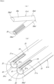
FIG. 1 is a perspective view of a microwave device according to an embodiment of the present invention when the microwave device is applied to a surgical instrument consisting of a thumb forceps-type instrument. -
FIG. 2(a) is a plan view of the tip end of the microwave radiating part according to the same embodiment,FIG. 2(b) is a vertical cross-sectional view of the tip end of the microwave irradiation part according to the same embodiment, andFIG. 2(c) is a cross-sectional view along a line A-A shown inFIG. 2(b), FIG. 2 (d-1) is a cross-sectional view along a line B-B shown inFIG. 2(b), and FIG. 2 (d-2) is an enlarged view of the broken line X portion shown inFIG. 2 (d-1). -
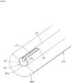
FIG. 3(a) is a perspective view of the microwave device according to the same embodiment when the microwave device is applied to a surgical instrument consisting of a forceps-type instrument, andFIG. 3(b) is a partially enlarged view of the surgical instrument body according to the same embodiment. -
FIG. 4 is a partially enlarged view of a surgical instrument body different from the one shown inFIG. 3 , showing a case according to the same embodiment when the microwave device is applied to a surgical instrument consisting of a forceps-type instrument - Hereinafter, one embodiment of a microwave device according to the present invention will be specifically described with reference to the drawings. It is noted that, in the following description, up/down and left/right directions shall be referred to as up/down and left/right directions when viewed from the front of the figure
- As an example of the application of the microwave device according to the present embodiment, for example, an application to a surgical instrument consisting of a thumb forceps-type instrument as shown in
FIG. 1 is exemplified. More specifically, as shown inFIG. 1 , the surgical instrument S consisting of a thumb forceps-type instrument, is composed of a pair of long and thin elliptical surgical instrument bodies Sa with tapered tip end portions. The base ends Sa1 of the pair of surgical instrument bodies Sa are fixed to each other, and the tip ends Sa2 are open. As a result, the pair of surgical instrument bodies Sa can approach and separate from each other, and the pair of surgical instrument bodies Sa can be used to hold and release biological tissues. - Further, the surgical instrument S configured in this way is provided with a
microwave device 1 as shown inFIG. 1 . Thismicrowave device 1 is composed of amicrowave introduction part 10 and amicrowave irradiation part 20, as shown inFIG. 1 . - As shown in
FIG. 1 , themicrowave introduction parts 10 are respectively provided on the base ends Sa1 side of the pair of surgical instrument bodies Sa, and themicrowave introduction parts 10 are composed of a coaxial cable having a conventionally known structure consisting of an inner conductor, an insulator, and an external conductor coaxially. Thus, suchmicrowave introduction parts 10 are connected to a microwave generator (not shown) or a branching filter provided in a microwave generator. As a result, microwaves generated by the microwave generator are introduced into themicrowave introduction parts 10. - As shown in
FIG. 1 , themicrowave irradiation parts 20 are respectively provided on the pair of surgical instrument bodies Sa so as to protrude from the tip ends Sa2 side of the pair of surgical instrument bodies Sa. As shown inFIG. 2(c) , themicrowave irradiation part 20 is composed of a coaxial cable consisting of thecentral conductor 21, theinsulator 22, and theexternal conductor 23 arranged coaxially. Thecentral conductor 21 is made of copper, bronze, aluminum, or the like, and has a circular shape in the cross-sectional view as shown inFIG. 2(c) and formed in a long rod-shape as shown inFIG. 2(b) . Thus, suchcentral conductor 21 is connected to or integrally formed with the inner conductor of themicrowave introduction part 10. Thereby, microwaves introduced into themicrowave introduction part 10 are transmitted to thecentral conductor 21. - As shown in
FIG. 2(c) , on the outer peripheral surface of thecentral conductor 21 as described above, theinsulator 22 formed in a circular shape in the cross-sectional view is coated so as to be coaxial with thecentral conductor 21. Furthermore, as shown inFIG. 2(b) , theinsulator 22 covers the outer peripheral surface of thecentral conductor 21 up to the tip end 20a of themicrowave irradiation part 20 so that thecentral conductor 21 is not exposed to the outside. In addition, theinsulator 22 is made of Teflon (registered trademark), ceramics, or the like. - As shown in
FIG. 2(c) , on the outer peripheral surface of theinsulator 22 as described above, anexternal conductor 23 formed in a circular shape in the cross-sectional view is coated so as to be coaxial with thecentral conductor 21 and theinsulator 22. Furthermore, as shown inFIG. 2(b) , theexternal conductor 23 covers the outer peripheral surface of thecentral insulator 22 up to the tip end 20a of themicrowave irradiation part 20 so that theinsulator 22 is not exposed to the outside. In addition, theexternal conductor 23 is formed of a conductive material such as a metal mesh. - The
central conductor 21 of themicrowave irradiation part 20 configured as described above is exposed to the outside for the first time from the tip end 20a of themicrowave irradiation part 20, as shown inFIG. 2(b) . Then, as shown inFIG. 2(b) , the externally exposed part 21a of thecentral conductor 21 exposed to the outside is bent along theexternal conductor 23 so as to extend toward thebase end portion 20b of themicrowave irradiation part 20 side (seeFIG. 1 ). As a result, microwaves transmitted from the externally exposed part 21a that is exposed to the outside for the first time from the tip end 20a of themicrowave irradiation part 20 to thecentral conductor 21 are radiated to the outside. Thereby, microwaves are radiated from the externally exposed part 21a that is bent along theexternal conductor 23 toward thebase end 20b side of the microwave irradiation part 20 (seeFIG. 1 ). Hence, microwaves are radiated from themicrowave irradiation parts 20 respectively provided at positions facing the pair of surgical instrument bodies Sa, and by holding the biological tissues with themicrowave irradiation part 20 of the pair of surgical instrument bodies Sa, not only can stopping bleeding and coagulating of the biological tissues be performed, but also coagulating can be performed while compressing separate biological tissues at the same time, thereby sealing of the biological tissues is achieved. - At this time, since the
central conductor 21 is exposed to the outside for the first time from the tip end 20a of themicrowave irradiation part 20, the amount of heat generated by microwaves at the tip end 20a can be increased compared to the conventional case. Therefore, since the amount of heat generated by microwaves at the tip end 20a which is frequently used is higher compared to the conventional case when themicrowave irradiation part 20 holds the biological tissues, it is capable of reducing the possibility that coagulation and hemostasis of biological tissues will not be performed successfully. - Thus, as in the present embodiment, by simply configuring where the
central conductor 21 is exposed to the outside for the first time from the tip end 20a of themicrowave irradiation part 20 and is bent along theexternal conductor 23 so as to extend toward thebase end portion 20b side of the microwave irradiation part 20 (seeFIG. 1 ), the amount of heat generated by microwaves at the tip end 20a can be increased compared to the conventional case. Therefore, the length and thickness of thecentral conductor 21 can be freely designed according to the desired microwaves wavelength. Of course, it is also possible to make the thickness of thecentral conductor 21 covered with theinsulator 22 and the externally exposed part 21a different. - Therefore, with a configuration like this embodiment, it is possible to solve the conventional problem of design limitations.
- By the way, in this embodiment, as shown in
FIGS. 2(a), (b), (d-1), and (d-2) , the externally exposed part 21a is arranged on the slit 23a formed on theexternal conductor 23. This is for the following reasons. - That is, when the externally exposed part 21a is bent along the
external conductor 23, microwaves radiated from the externally exposed part 21a become diffused to the surroundings without controlling the directivity of microwaves. Therefore, even if an attempt is made to acutely coagulate and stop bleeding of the biological tissues by holding the biological tissues with themicrowave irradiation part 20, since microwaves are diffused in the surroundings, it is possible that the coagulation and hemostasis of the biological tissues may not be acutely performed. - Therefore, in this embodiment, it is configured so that the directivity of microwaves is controlled by forming the slit 23a on the
external conductor 23 and arranging the externally exposed part 21a on the slit 23a. More specifically, as shown inFIGS. 2 (d-1) and 2(d-2), the slit 23a is formed in a generally concave shape in cross-sectional view, in a state where a part of theexternal conductor 23 is cut away, and as shown inFIGS. 2(a) and 2(b) , the slit 23a is provided in an elongated shape on one side surface (in the drawing shown on upper surface ) of theexternal conductor 23 extending (from the tip end 20a side to thebase end 20b side of themicrowave irradiation part 20, seeFIG. 1 ) in the axial direction of theexternal conductor 23. Further, as shown inFIG. 2 (d-2), the external peripheral surface of the slit 23a is covered with aninsulator 24 made of Teflon (registered trademark), ceramics, or the like. Thus, the externally exposed part 21a is arranged on the slit 23a formed in this way. As a result, when the externally exposed part 21a radiates the left wall surface 23al side of the slit 23a with microwaves as shown inFIG. 2 (d-2), microwaves are cut off by theinsulator 24 covering the left wall surface 23a1 side and an electric discharge due to microwaves is prevented. Furthermore, when the externally exposed part 21a radiates the right wall surface 23a2 side of the slit 23a with microwaves as shown inFIG. 2 (d-2), microwaves are cut off by theinsulator 24 covering the right wall surface 23a1 side and an electric discharge due to microwaves is prevented.
Furthermore, when the externally exposed part 21a radiates the bottom wall surface 23a3 side of the slit 23a with microwaves as shown inFIG. 2 (d-2), microwaves are cut off by theinsulator 24 covering the bottom wall surface 23a3 side and an electric discharge due to microwaves is prevented. Ultimately, therefore, microwaves are radiated in the direction of arrow Y1 (upward direction in the drawing) shown inFIG. 2 (d-2) and thus the directivity of microwaves can be controlled. As a result, when themicrowave irradiation parts 20 hold the biological tissues, specific portions of the biological tissues are radiated with microwaves, so that the coagulation and hemostasis of biological tissues can be performed acutely. - The reason why the outer peripheral surface of the slit 23a is covered with the
insulator 24 as described above is to prevent the externally exposed part 21a and theexternal conductor 23 from coming into contact with each other. That is, when the externally exposed part 21a and theexternal conductor 23 are brought into contact with each other, microwaves radiated from the externally exposed part 21a will be in a state like a loop antenna in which microwaves only flow into theexternal conductor 23. Thereby it may cause a possibility that the biological tissues are not radiated with microwaves. Therefore, in this embodiment, when the externally exposed part 21a is bent along theexternal conductor 23, as shown inFIG. 2 (d-2) the outer peripheral surface of the slit 23a is covered with theinsulator 24 so that the externally exposed part 21a and theexternal conductor 23 will not be brought into contact with each other. As a result, the loop antenna-like state is prevented, and a situation in which the biological tissues are not radiated with microwaves is prevented. - According to the present embodiment described above, the amount of heat generated at the tip end portion can be increased.
- It should be noted that the shapes and the like shown in this embodiment are merely examples, and various modifications and changes are possible within the scope of the gist of the invention described in the claims. For example, the shape of the
microwave device 1 shown in this embodiment is merely an example, and any shape may be used. For example, in themicrowave device 1 exemplified in this embodiment, the shape of the externally exposed part 21a can be changed to various shapes such as a fan shape, a rectangular shape, a triangular shape, or the like, other than the circular shape in the cross-sectional view. - In this embodiment, an example is shown in which when the slit 23a is formed on the
external conductor 23, and the outer peripheral surface thereof is covered with theinsulator 24, however, it is enough just to provide a gap between the externally exposed part 21a and theexternal conductor 23 without covering the outer peripheral surface of the slit 23a with theinsulator 24. The point is that the externally exposed part 21a and theexternal conductor 23 should not be brought into contact with each other, any method may be used to prevent them from coming into contact with each other. However, when a gap is provided between the externally exposed part 21a and theexternal conductor 23, there is a possibility that microwaves may be discharged through the air present in the gap between the slit 23 a and the externally exposed part 21a. Therefore, it is preferable to cover the outer peripheral surface of the slit 23a with theinsulator 24. In addition, the shape of the slit 23a is not limited to the concave shape, and may be any shape. - Further, in this embodiment, a thumb forceps-type instrument is exemplified as the surgical instrument S, but the present invention is not limited thereto, and can be applied to various surgical instruments such as forceps-type instruments and scissors-type instruments. Furthermore, if it is applied to a deep coagulation antenna, it can be applied to a directional tumor coagulation therapy. That is, it can be used with minimal thermal damage to nearby nerves, bile ducts, gallbladders, blood vessels, trachea, ureters, urethra, and the like.
- Further, in the present embodiment, an example in which the
microwave irradiation parts 20 are respectively provided in a pair of surgical instrument bodies Sa is shown, but the present invention is not limited to this, and a plurality ofmicrowave irradiation parts 20 may be provided in one surgical instrument body Sa. This point will be described with reference toFIG. 3 , in which the same reference numerals are given to the same configurations as those described above, and the description thereof will be omitted. - As the surgical instrument SA shown in
FIG. 3(a) , a surgical instrument consisting of a forceps-type instrument is exemplified. The surgical instrument SA is composed of a pair of surgical instrument main bodies SAa each having an elongated elliptical shape. The base ends SAa1 of the pair of surgical instrument bodies SAa are fixed to each other, and the tip ends SAa2 are open. As a result, the pair of surgical instrument bodies SAa can approach and separate from each other, so that the pair of surgical instrument bodies SAa can be used to hold and release biological tissues. - One of thus formed pair of surgical instrument bodies SAa (lower one in
FIG. 3(a) ) is provided with twomicrowave irradiation parts 20 arranged in parallel. Thus, in this way, when the pair of surgical instrument main body SAa hold biological tissues, and microwaves are radiated at the twomicrowave irradiation parts 20, better coagulation and hemostasis of biological tissues can be achieved. - Note that
FIG. 3 exemplifies a case where one of the pair of surgical instrument bodies SAa (lower one inFIG. 3(a) ) is provided with twomicrowave irradiation parts 20 arranged in parallel. However, not limited to this, the other surgical instrument main body Sa (upper one inFIG. 3A ) may also have twomicrowave irradiation parts 20 arranged in parallel. - Further,
FIG. 3 shows an example in which twomicrowave irradiation parts 20 are arranged in parallel as the surgical instrument SA consisting of a forceps-type instrument, but of course, as shown inFIG. 4 , a singlemicrowave irradiation parts 20 may be arranged. - Although not shown in the drawings, a
microwave introduction part 10 is provided on the side of the pair of surgical instrument main bodies SAa. -
- 1
- microwave device
- 20
- microwave irradiation part
- 20a
- tip end (tip end of the microwave device)
- 20b
- base end (base end of microwave device)
- 21
- central conductor
- 21a
- externally exposed part
- 22
- insulator
- 23
- external conductor
- 23a
- slit
- 24
- insulator
Claims (3)
- A microwave device capable of radiating microwaves, comprising:a central conductor that transmits microwaves,an insulator covering the central conductor, andan external conductor covering the insulator, whereinthe central conductor is exposed to the outside from a tip end of the microwave device for the first time, andan externally exposed part of the exposed central conductor is bent toward a base end side of the microwave device so as to be along the external conductor.
- The microwave device according to claim 1, whereina slit toward the base end side of the microwave device is formed on the external conductor, andthe externally exposed part of the central conductor is arranged on the slit.
- The microwave device according to claim 1 or 2, wherein
the externally exposed part of the central conductor is bent so as not to come into contact with the external conductor.
Applications Claiming Priority (2)
| Application Number | Priority Date | Filing Date | Title |
|---|---|---|---|
| JP2021128221 | 2021-08-04 | ||
| PCT/JP2022/023051 WO2023013239A1 (en) | 2021-08-04 | 2022-06-08 | Microwave device |
Publications (3)
| Publication Number | Publication Date |
|---|---|
| EP4382063A1 true EP4382063A1 (en) | 2024-06-12 |
| EP4382063A4 EP4382063A4 (en) | 2024-10-16 |
| EP4382063B1 EP4382063B1 (en) | 2025-08-06 |
Family
ID=85154097
Family Applications (1)
| Application Number | Title | Priority Date | Filing Date |
|---|---|---|---|
| EP22851009.5A Active EP4382063B1 (en) | 2021-08-04 | 2022-06-08 | Microwave device |
Country Status (5)
| Country | Link |
|---|---|
| US (1) | US12614651B2 (en) |
| EP (1) | EP4382063B1 (en) |
| JP (1) | JP7592174B2 (en) |
| CN (1) | CN117440784A (en) |
| WO (1) | WO2023013239A1 (en) |
Family Cites Families (7)
| Publication number | Priority date | Publication date | Assignee | Title |
|---|---|---|---|---|
| US4557272A (en) * | 1980-03-31 | 1985-12-10 | Microwave Associates, Inc. | Microwave endoscope detection and treatment system |
| WO1993020886A1 (en) * | 1992-04-13 | 1993-10-28 | Ep Technologies, Inc. | Articulated systems for cardiac ablation |
| US8080009B2 (en) * | 2005-07-01 | 2011-12-20 | Halt Medical Inc. | Radio frequency ablation device for the destruction of tissue masses |
| US7826904B2 (en) * | 2006-02-07 | 2010-11-02 | Angiodynamics, Inc. | Interstitial microwave system and method for thermal treatment of diseases |
| US10842564B2 (en) | 2011-08-10 | 2020-11-24 | National University Corporation Shiga University Of Medical Science | Microwave surgical instrument |
| JP6177049B2 (en) | 2013-08-21 | 2017-08-09 | 日機装株式会社 | Microwave tissue coagulation instrument |
| GB201814399D0 (en) * | 2018-09-05 | 2018-10-17 | Emblation Ltd | Directional antenna |
-
2022
- 2022-06-08 EP EP22851009.5A patent/EP4382063B1/en active Active
- 2022-06-08 JP JP2023539677A patent/JP7592174B2/en active Active
- 2022-06-08 CN CN202280030500.2A patent/CN117440784A/en active Pending
- 2022-06-08 WO PCT/JP2022/023051 patent/WO2023013239A1/en not_active Ceased
-
2023
- 2023-10-30 US US18/497,647 patent/US12614651B2/en active Active
Also Published As
| Publication number | Publication date |
|---|---|
| EP4382063A4 (en) | 2024-10-16 |
| US20240105361A1 (en) | 2024-03-28 |
| WO2023013239A1 (en) | 2023-02-09 |
| JP7592174B2 (en) | 2024-11-29 |
| JPWO2023013239A1 (en) | 2023-02-09 |
| CN117440784A (en) | 2024-01-23 |
| US12614651B2 (en) | 2026-04-28 |
| EP4382063B1 (en) | 2025-08-06 |
Similar Documents
| Publication | Publication Date | Title |
|---|---|---|
| US9949794B2 (en) | Microwave ablation devices including expandable antennas and methods of use | |
| CN103190950B (en) | Systems and methods for treating tissue using expandable antennas | |
| JP5688814B2 (en) | Surgical antenna and electrosurgical system using the same | |
| JP2008142467A (en) | Coaxial probe | |
| JP2010194317A (en) | Leaky-wave antenna for medical application | |
| JP2004267644A (en) | Electrodes for biological tissue processing | |
| Luyen et al. | Reduced-diameter designs of coax-fed microwave ablation antennas equipped with baluns | |
| US10993767B2 (en) | Microwave ablation antenna assemblies | |
| US20180256251A1 (en) | Microwave ablation antenna system with slot balun | |
| EP2742893A1 (en) | Microwave surgical instrument | |
| US11172985B2 (en) | Electrosurgical snare | |
| EP4382063B1 (en) | Microwave device | |
| CN110461264B (en) | Electrosurgical instruments for ablation and resection | |
| Luyen et al. | A minimally invasive, coax-fed microwave ablation antenna with a tapered-slot balun | |
| JP2003079635A (en) | Living body tissue treatment apparatus | |
| HK40019816B (en) | Electrosurgical apparatus for delivering rf and/or microwave energy into biological tissue | |
| HK40015147A (en) | Electrosurgical instrument for ablation and resection |
Legal Events
| Date | Code | Title | Description |
|---|---|---|---|
| STAA | Information on the status of an ep patent application or granted ep patent |
Free format text: STATUS: THE INTERNATIONAL PUBLICATION HAS BEEN MADE |
|
| PUAI | Public reference made under article 153(3) epc to a published international application that has entered the european phase |
Free format text: ORIGINAL CODE: 0009012 |
|
| STAA | Information on the status of an ep patent application or granted ep patent |
Free format text: STATUS: REQUEST FOR EXAMINATION WAS MADE |
|
| 17P | Request for examination filed |
Effective date: 20231030 |
|
| AK | Designated contracting states |
Kind code of ref document: A1 Designated state(s): AL AT BE BG CH CY CZ DE DK EE ES FI FR GB GR HR HU IE IS IT LI LT LU LV MC MK MT NL NO PL PT RO RS SE SI SK SM TR |
|
| A4 | Supplementary search report drawn up and despatched |
Effective date: 20240912 |
|
| RIC1 | Information provided on ipc code assigned before grant |
Ipc: A61B 18/18 20060101AFI20240906BHEP |
|
| DAV | Request for validation of the european patent (deleted) | ||
| DAX | Request for extension of the european patent (deleted) | ||
| GRAP | Despatch of communication of intention to grant a patent |
Free format text: ORIGINAL CODE: EPIDOSNIGR1 |
|
| STAA | Information on the status of an ep patent application or granted ep patent |
Free format text: STATUS: GRANT OF PATENT IS INTENDED |
|
| INTG | Intention to grant announced |
Effective date: 20250327 |
|
| GRAS | Grant fee paid |
Free format text: ORIGINAL CODE: EPIDOSNIGR3 |
|
| GRAA | (expected) grant |
Free format text: ORIGINAL CODE: 0009210 |
|
| STAA | Information on the status of an ep patent application or granted ep patent |
Free format text: STATUS: THE PATENT HAS BEEN GRANTED |
|
| P01 | Opt-out of the competence of the unified patent court (upc) registered |
Free format text: CASE NUMBER: APP_26994/2025 Effective date: 20250606 |
|
| AK | Designated contracting states |
Kind code of ref document: B1 Designated state(s): AL AT BE BG CH CY CZ DE DK EE ES FI FR GB GR HR HU IE IS IT LI LT LU LV MC MK MT NL NO PL PT RO RS SE SI SK SM TR |
|
| REG | Reference to a national code |
Ref country code: GB Ref legal event code: FG4D |
|
| REG | Reference to a national code |
Ref country code: CH Ref legal event code: EP |
|
| REG | Reference to a national code |
Ref country code: IE Ref legal event code: FG4D |
|
| REG | Reference to a national code |
Ref country code: DE Ref legal event code: R096 Ref document number: 602022019148 Country of ref document: DE |
|
| REG | Reference to a national code |
Ref country code: NL Ref legal event code: MP Effective date: 20250806 |
|
| PG25 | Lapsed in a contracting state [announced via postgrant information from national office to epo] |
Ref country code: IS Free format text: LAPSE BECAUSE OF FAILURE TO SUBMIT A TRANSLATION OF THE DESCRIPTION OR TO PAY THE FEE WITHIN THE PRESCRIBED TIME-LIMIT Effective date: 20251206 |
|
| PG25 | Lapsed in a contracting state [announced via postgrant information from national office to epo] |
Ref country code: NO Free format text: LAPSE BECAUSE OF FAILURE TO SUBMIT A TRANSLATION OF THE DESCRIPTION OR TO PAY THE FEE WITHIN THE PRESCRIBED TIME-LIMIT Effective date: 20251106 |
|
| REG | Reference to a national code |
Ref country code: LT Ref legal event code: MG9D |
|
| PG25 | Lapsed in a contracting state [announced via postgrant information from national office to epo] |
Ref country code: PT Free format text: LAPSE BECAUSE OF FAILURE TO SUBMIT A TRANSLATION OF THE DESCRIPTION OR TO PAY THE FEE WITHIN THE PRESCRIBED TIME-LIMIT Effective date: 20251209 |
|
| PG25 | Lapsed in a contracting state [announced via postgrant information from national office to epo] |
Ref country code: FI Free format text: LAPSE BECAUSE OF FAILURE TO SUBMIT A TRANSLATION OF THE DESCRIPTION OR TO PAY THE FEE WITHIN THE PRESCRIBED TIME-LIMIT Effective date: 20250806 |
|
| PG25 | Lapsed in a contracting state [announced via postgrant information from national office to epo] |
Ref country code: HR Free format text: LAPSE BECAUSE OF FAILURE TO SUBMIT A TRANSLATION OF THE DESCRIPTION OR TO PAY THE FEE WITHIN THE PRESCRIBED TIME-LIMIT Effective date: 20250806 Ref country code: NL Free format text: LAPSE BECAUSE OF FAILURE TO SUBMIT A TRANSLATION OF THE DESCRIPTION OR TO PAY THE FEE WITHIN THE PRESCRIBED TIME-LIMIT Effective date: 20250806 |
|
| PG25 | Lapsed in a contracting state [announced via postgrant information from national office to epo] |
Ref country code: GR Free format text: LAPSE BECAUSE OF FAILURE TO SUBMIT A TRANSLATION OF THE DESCRIPTION OR TO PAY THE FEE WITHIN THE PRESCRIBED TIME-LIMIT Effective date: 20251107 |
|
| PG25 | Lapsed in a contracting state [announced via postgrant information from national office to epo] |
Ref country code: SE Free format text: LAPSE BECAUSE OF FAILURE TO SUBMIT A TRANSLATION OF THE DESCRIPTION OR TO PAY THE FEE WITHIN THE PRESCRIBED TIME-LIMIT Effective date: 20250806 |
|
| PG25 | Lapsed in a contracting state [announced via postgrant information from national office to epo] |
Ref country code: LV Free format text: LAPSE BECAUSE OF FAILURE TO SUBMIT A TRANSLATION OF THE DESCRIPTION OR TO PAY THE FEE WITHIN THE PRESCRIBED TIME-LIMIT Effective date: 20250806 |
|
| PG25 | Lapsed in a contracting state [announced via postgrant information from national office to epo] |
Ref country code: PL Free format text: LAPSE BECAUSE OF FAILURE TO SUBMIT A TRANSLATION OF THE DESCRIPTION OR TO PAY THE FEE WITHIN THE PRESCRIBED TIME-LIMIT Effective date: 20250806 Ref country code: BG Free format text: LAPSE BECAUSE OF FAILURE TO SUBMIT A TRANSLATION OF THE DESCRIPTION OR TO PAY THE FEE WITHIN THE PRESCRIBED TIME-LIMIT Effective date: 20250806 |
|
| PG25 | Lapsed in a contracting state [announced via postgrant information from national office to epo] |
Ref country code: RS Free format text: LAPSE BECAUSE OF FAILURE TO SUBMIT A TRANSLATION OF THE DESCRIPTION OR TO PAY THE FEE WITHIN THE PRESCRIBED TIME-LIMIT Effective date: 20251106 |
|
| PG25 | Lapsed in a contracting state [announced via postgrant information from national office to epo] |
Ref country code: ES Free format text: LAPSE BECAUSE OF FAILURE TO SUBMIT A TRANSLATION OF THE DESCRIPTION OR TO PAY THE FEE WITHIN THE PRESCRIBED TIME-LIMIT Effective date: 20250806 |
|
| REG | Reference to a national code |
Ref country code: AT Ref legal event code: MK05 Ref document number: 1820862 Country of ref document: AT Kind code of ref document: T Effective date: 20250806 |
|
| PG25 | Lapsed in a contracting state [announced via postgrant information from national office to epo] |
Ref country code: SM Free format text: LAPSE BECAUSE OF FAILURE TO SUBMIT A TRANSLATION OF THE DESCRIPTION OR TO PAY THE FEE WITHIN THE PRESCRIBED TIME-LIMIT Effective date: 20250806 |
|
| PG25 | Lapsed in a contracting state [announced via postgrant information from national office to epo] |
Ref country code: DK Free format text: LAPSE BECAUSE OF FAILURE TO SUBMIT A TRANSLATION OF THE DESCRIPTION OR TO PAY THE FEE WITHIN THE PRESCRIBED TIME-LIMIT Effective date: 20250806 |
|
| PG25 | Lapsed in a contracting state [announced via postgrant information from national office to epo] |
Ref country code: AT Free format text: LAPSE BECAUSE OF FAILURE TO SUBMIT A TRANSLATION OF THE DESCRIPTION OR TO PAY THE FEE WITHIN THE PRESCRIBED TIME-LIMIT Effective date: 20250806 |
|
| PG25 | Lapsed in a contracting state [announced via postgrant information from national office to epo] |
Ref country code: IT Free format text: LAPSE BECAUSE OF FAILURE TO SUBMIT A TRANSLATION OF THE DESCRIPTION OR TO PAY THE FEE WITHIN THE PRESCRIBED TIME-LIMIT Effective date: 20250806 |
|
| PG25 | Lapsed in a contracting state [announced via postgrant information from national office to epo] |
Ref country code: CZ Free format text: LAPSE BECAUSE OF FAILURE TO SUBMIT A TRANSLATION OF THE DESCRIPTION OR TO PAY THE FEE WITHIN THE PRESCRIBED TIME-LIMIT Effective date: 20250806 |
|
| PG25 | Lapsed in a contracting state [announced via postgrant information from national office to epo] |
Ref country code: EE Free format text: LAPSE BECAUSE OF FAILURE TO SUBMIT A TRANSLATION OF THE DESCRIPTION OR TO PAY THE FEE WITHIN THE PRESCRIBED TIME-LIMIT Effective date: 20250806 Ref country code: SK Free format text: LAPSE BECAUSE OF FAILURE TO SUBMIT A TRANSLATION OF THE DESCRIPTION OR TO PAY THE FEE WITHIN THE PRESCRIBED TIME-LIMIT Effective date: 20250806 |