EP4382015A1 - Steam cleaning apparatus - Google Patents
Steam cleaning apparatus Download PDFInfo
- Publication number
- EP4382015A1 EP4382015A1 EP23214446.9A EP23214446A EP4382015A1 EP 4382015 A1 EP4382015 A1 EP 4382015A1 EP 23214446 A EP23214446 A EP 23214446A EP 4382015 A1 EP4382015 A1 EP 4382015A1
- Authority
- EP
- European Patent Office
- Prior art keywords
- cleaning apparatus
- steam
- steam cleaning
- box body
- box cover
- Prior art date
- Legal status (The legal status is an assumption and is not a legal conclusion. Google has not performed a legal analysis and makes no representation as to the accuracy of the status listed.)
- Granted
Links
Images


Classifications
-
- A—HUMAN NECESSITIES
- A47—FURNITURE; DOMESTIC ARTICLES OR APPLIANCES; COFFEE MILLS; SPICE MILLS; SUCTION CLEANERS IN GENERAL
- A47L—DOMESTIC WASHING OR CLEANING; SUCTION CLEANERS IN GENERAL
- A47L11/00—Machines for cleaning floors, carpets, furniture, walls, or wall coverings
- A47L11/40—Parts or details of machines not provided for in groups A47L11/02 - A47L11/38, or not restricted to one of these groups, e.g. handles, arrangements of switches, skirts, buffers, levers
- A47L11/408—Means for supplying cleaning or surface treating agents
- A47L11/4083—Liquid supply reservoirs; Preparation of the agents, e.g. mixing devices
-
- A—HUMAN NECESSITIES
- A47—FURNITURE; DOMESTIC ARTICLES OR APPLIANCES; COFFEE MILLS; SPICE MILLS; SUCTION CLEANERS IN GENERAL
- A47L—DOMESTIC WASHING OR CLEANING; SUCTION CLEANERS IN GENERAL
- A47L11/00—Machines for cleaning floors, carpets, furniture, walls, or wall coverings
- A47L11/34—Machines for treating carpets in position by liquid, foam, or vapour, e.g. by steam
-
- A—HUMAN NECESSITIES
- A47—FURNITURE; DOMESTIC ARTICLES OR APPLIANCES; COFFEE MILLS; SPICE MILLS; SUCTION CLEANERS IN GENERAL
- A47L—DOMESTIC WASHING OR CLEANING; SUCTION CLEANERS IN GENERAL
- A47L11/00—Machines for cleaning floors, carpets, furniture, walls, or wall coverings
- A47L11/40—Parts or details of machines not provided for in groups A47L11/02 - A47L11/38, or not restricted to one of these groups, e.g. handles, arrangements of switches, skirts, buffers, levers
- A47L11/408—Means for supplying cleaning or surface treating agents
- A47L11/4086—Arrangements for steam generation
-
- A—HUMAN NECESSITIES
- A47—FURNITURE; DOMESTIC ARTICLES OR APPLIANCES; COFFEE MILLS; SPICE MILLS; SUCTION CLEANERS IN GENERAL
- A47L—DOMESTIC WASHING OR CLEANING; SUCTION CLEANERS IN GENERAL
- A47L11/00—Machines for cleaning floors, carpets, furniture, walls, or wall coverings
- A47L11/40—Parts or details of machines not provided for in groups A47L11/02 - A47L11/38, or not restricted to one of these groups, e.g. handles, arrangements of switches, skirts, buffers, levers
- A47L11/408—Means for supplying cleaning or surface treating agents
- A47L11/4088—Supply pumps; Spraying devices; Supply conduits
-
- A—HUMAN NECESSITIES
- A47—FURNITURE; DOMESTIC ARTICLES OR APPLIANCES; COFFEE MILLS; SPICE MILLS; SUCTION CLEANERS IN GENERAL
- A47L—DOMESTIC WASHING OR CLEANING; SUCTION CLEANERS IN GENERAL
- A47L11/00—Machines for cleaning floors, carpets, furniture, walls, or wall coverings
- A47L11/40—Parts or details of machines not provided for in groups A47L11/02 - A47L11/38, or not restricted to one of these groups, e.g. handles, arrangements of switches, skirts, buffers, levers
- A47L11/4091—Storing or parking devices, arrangements therefor; Means allowing transport of the machine when it is not being used
Definitions
- the present disclosure relates to the technical field of cleaning appliances, and more particularly to a steam cleaning apparatus.
- a steam cleaning apparatus is a tool for dissolving stubborn dirt attached to objects and performing sterilization and disinfection by high-temperature steam.
- the steam cleaning apparatus can be used for sterilization, fine dust removal, decontamination, oil stain removal, and is widely used in personal household deep cleaning and housekeeping fields.
- existing steam cleaning apparatus typically include a plurality of accessories.
- Steam cleaning apparatus are usually equipped with a receiving box for accommodating all accessories.
- An object of the present invention is to prolong a continuous operating time of a steam cleaning apparatus.
- a steam cleaning apparatus includes: a box body having a receiving space; a box cover connected with the box body in an opening and closing manner, wherein the box cover is configured as a water tank for the steam cleaning apparatus; a steam control device arranged in the box body and outside the receiving space; and an accessory in fluid communication or connection with the steam control device and adapted to be accommodated in the receiving space.
- the box cover is removably connected with the box body.
- the box cover is provided with a buckle fitting part
- the box body is provided with a buckle for connecting with the buckle fitting part to lock the box cover and the box body.
- two sides of the box cover opposite each other are respectively provided with a buckle.
- the buckle is arranged on a side of the box cover away from a water outlet.
- the box cover is further provided with a lifting part for lifting the box cover.
- the box cover includes: a water tank body; a water inlet arranged on one side of the water tank body; and a water outlet arranged on the opposite side of the water tank body; wherein the water tank body is in fluid communication with the steam control device via the water outlet.
- the box cover further includes a water tank cover connected with the water inlet in an opening and closing manner.
- the water tank body is provided with a groove on one side of the water tank body facing the box body.
- the steam control device includes: a controller; a water pump connected with the controller; and a boiler having a first port connected with the water pump and having a second port connected with a steam pipe.
- the steam control device further includes a safety valve connected with the water pump for controlling a pressure of the water pump.
- the steam control device further includes a status indicator light arranged on the box body and connected with the controller for indicating a status of the steam cleaning apparatus.
- the steam control device further includes an inlet component for providing an inlet of the steam control device and a water level detector suitable for the inlet of the steam control device.
- the steam control device further includes a descaling bucket comprising a first port connected with the inlet component and a second port connected with the water pump.
- the steam cleaning apparatus further includes a handle arranged outside of the box cover and connected with the box body.
- the box body has a handle connecting part
- the handle has an installing part for mating with the handle connecting part
- the handle connecting part is rotatably connected with the installing part and remains fixed relative to the installing part when rotated to a position above the box cover.
- the steam cleaning apparatus further includes a power cord, wherein a side wall of the box body is provided with a cord outlet, and the power cord extends to outside of the box body via the cord outlet.
- the box body is provided with a mesh part for accommodating the power cord on the side wall of the box body provided with the cord outlet.
- the box body has a steam pipe outlet.
- the box cover is connected with the box body in an opening and closing manner, and serves as a cover of the box body, and on the other hand, the box cover also serves as a water tank of the steam cleaning apparatus for providing a water source for the steam cleaning apparatus. Since the box cover is arranged on the box body, the size of the water tank can be larger compared to being arranged in the receiving space provided by the box body, which can increase the volume of the water tank and increase the continuous operating time of the steam cleaning apparatus. In addition, the receiving space provided by the box body can meet accommodating needs, and prolong the continuous operating time of the steam cleaning apparatus while meeting the accommodating needs.
- Existing steam cleaning apparatus are usually equipped with a receiving box for accommodating accessories of the steam cleaning apparatus, including a water tank, a steam pipe, a steam handle, a steam nozzle, a steam brush, a circular brush and a detail nozzle, etc.
- the present invention provides a steam cleaning apparatus.
- a box cover is connected with a box body in an opening and closing manner, and serves as a cover of the box body, and on the other hand, the box cover also serves as a water tank of the steam cleaning apparatus for providing a water source for the steam cleaning apparatus. Since the box cover is arranged on the box body, the size of the water tank can be larger compared to being arranged in the receiving space provided by the box body, which can increase a volume of the water tank and increase a continuous operating time of the steam cleaning apparatus.
- a steam cleaning apparatus includes: a box body having a receiving space; a box cover connected with the box body in an opening and closing manner, wherein the box cover is configured as a water tank for the steam cleaning apparatus; a steam control device arranged in the box body and outside the receiving space; and an accessory in fluid communication or connection with the steam control device and adapted to be accommodated in the receiving space.
- the box body provides the receiving space, which allows the accessories to be accommodated in the receiving space, thus the storage of various accessories of the steam cleaning apparatus can be more tidy.
- the box cover can convert the receiving space into a closed space, which can facilitate the movement of the steam cleaning apparatus.
- the box cover also serves as the water tank for providing a water source and is not limited by the receiving space, which prolongs the continuous operating time of the steam cleaning apparatus without an additional water tank and water tank cover, thereby reducing the overall weight of the steam cleaning apparatus.
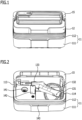
- FIG. 1 is a schematic view of a steam cleaning apparatus in a closed state according to an embodiment of the present invention
- FIG. 2 is a schematic view of the steam cleaning apparatus in an opened state according to an embodiment of the present invention
- the steam cleaning apparatus includes a box body 11, a box cover 12 and a steam control device.
- the box body 11 provides a receiving space
- the box cover 12 serves as an upper cover and a water tank of the box body 11.
- the box body 11 includes a lower cover 111 and a middle frame 112, and the receiving space is located in the middle frame 112.
- the steam control device is arranged in the lower cover 111 and outside the middle frame 112, and the receiving space can partially surround the steam control device.
- the box cover 12 is connected with the box body 11 in an opening and closing manner, that is, the box cover 12 can be in a closed position or in an open position relative to the box body 11. When the box cover 12 is in the closed position relative to the box body 11, the receiving space is closed and an overall storage is more tidy.
- the shape of the receiving space is not limited as long as it can accommodate various accessories.
- the box cover 12 has a hollow structure suitable for receiving water.
- the material of the box cover 12 may be polypropylene (PP) or high density polyethylene (HDPE).
- a thickness of a side wall of the box cover 12 ranges from 1 mm to 3mm. If the side wall of the box cover 12 is too thick, a volume of the water tank can be reduced. If the side wall of the box cover 12 is too thin, the box cover 12 cannot withstand enough pressure and is easy to crack.
- a shape of the box body 11 matches with a shape of the box cover 12.
- both the box body 11 and the box cover 12 may have a rectangular shape.
- the box body 11 and the box cover 12 may also have other shapes, which are not limited herein.
- the box cover 12 may be fixedly connected with the box body 11 (such as a hinge connection), that is, the box cover 12 may be non-removably connected with the box body 11. At this time, the box body 11 remains fixed and the box cover 12 can rotate around a connection axis between the box body 11 and the box cover 12.
- the box cover 12 since the box cover 12 serves as the water tank, the box cover 12 may be removably connected with the box body 11, which can facilitate the removal of the box cover 12 from the box body 11 so that box cover 12 can be filled with water.
- FIG. 3 is a schematic top view of a box cover according to an embodiment of the present disclosure
- FIG. 4 is a schematic bottom view of the box cover according to an embodiment of the present disclosure.
- the box cover 12 may be provided with a buckle fitting part 121
- the box body 11 may be provided with a buckle 113 (referring to FIG. 2 ).
- the buckle 113 is adapted to be connected with the buckle fitting part 121 to lock the box cover 12 and the box body 11.
- the buckle 113 and the buckle fitting part 121 can match with each other in shape and size.
- two buckle fitting parts 121 may be symmetrically arranged on two opposite sides of the box body 11 in the form of a triangular protrusion.
- the buckle 113 can clamp a top of the buckle fitting port 121 to lock the box cover 12 and the box body 11, which can prevent the box cover 12 from falling off the box body 11 during the movement of the steam cleaning apparatus, thus the closure of the box cover 12 and the box body 11 is more stable, which is beneficial to the movement of the steam cleaning apparatus.
- the buckle may also be arranged on a side of the box cover away from a water outlet.
- only one buckle is arranged on the box cover, and correspondingly, only one buckle fitting part is arranged on the box body.
- the buckle on the box cover can be mated with the buckle fitting part on the box body to lock one side of the box cover and the box body.
- the steam control device has an inlet component that can provide an inlet for the steam control device.
- the inlet of the steam control device can match with a water outlet of the box cover, so that the water in the box cover can flow into the steam control device without leakage.
- the inlet of the steam control device and the water outlet of the box cover are usually made of a soft rubber material.
- an interference fit is formed between the inlet of the steam control device and the water outlet of the box cover, making the inlet of the steam control device and the water outlet of the box cover tightly connected with each other, thereby locking the other side of the box cover and the box body. Therefore, an additional buckle and buckle fitting part are not needed to be installed on the other side of the box cover and the box body, which can simplify manufacturing complexity and save costs.
- the box cover 12 is further provided with a lifting part 122 suitable for lifting the box cover 12. Specifically, after the box cover 12 is unlocked, the box cover 12 can be lifted from the box body 11 by holding the lifting part 122 and pulling the lifting part 122 upwards. During installation, by holding the lifting part 122, the box cover 12 can be installed on the box body 11, and then the buckle fitting part is tightly locked by the buckle.
- the box cover 12 can have various shapes. In general, for better appearance, the box cover 12 and the box body 11 can be arranged symmetrically. After removing the box cover 12 from the box body 11, the box cover 12 can be used as a handheld part to fill the box cover 12 with water, or both sides of the box cover 12 can be used as handheld parts to fill the box cover 12 with water.
- the box cover 12 may include a water tank body 123, a water inlet 124 arranged on one side of the water tank body 123 and a water outlet 125 arranged on the other side of the water tank body 123.
- the water tank body 123 is in fluid communication with the steam control device through the water outlet 125.
- the water can be filled into the water tank body 123 through the water inlet 124.
- the water in the water tank body 123 flows into the steam control device through the water outlet 125.
- a plurality of reinforcing ribs 127 may be arranged on an upper surface of the water tank body 123, which can increase a strength of the water tank body 123 and improve a pressure resistance of the box cover 12.
- the box cover 12 may also include a water tank cover 128 having a sealing function.
- the water tank cover 128 can tightly cover the water inlet 124 to prevent the water tank from leaking.
- the water tank cover 128 can be made of any suitable elastomer, such as silicone.
- a groove may be arranged on a side of the water tank body 123 facing the box body 11.
- the groove may be recessed towards the upper surface of the water tank body 123, which can increase the receiving space to accommodate more accessories.
- the accessories may include a steam handle 131 and a steam pipe 132.
- the accessories may also include a steam nozzle, a steam brush, a circular brush, a detail nozzle, and a shovel, etc.
- not all accessories are shown for the sake of simplification.
- a handle fixing portion 133 is arranged in the receiving space.
- the handle fixing portion 133 can fix the steam handle 131 in the receiving space to avoid shaking due to displacement.
- Other accessories can be arranged in a gap between the steam handle 131, the steam pipe 132 and the receiving space.
- the steam control device includes a controller (not shown in the figure), a water pump 144 connected with the controller and a boiler 145 with one end connected with the water pump 144 and the other end connected with a steam pipe.
- the steam control device further includes an inlet component 141 for providing an inlet of the steam control device and a water level detector suitable for the inlet of the steam control device.
- the inlet component 141 may be connected with the controller to send water level detection results to the controller, which controls the operation of the steam cleaning apparatus based on the water level detection results.
- the steam control device may further include a safety valve 146.
- the safety valve 146 is connected with the water pump 144 for adjusting a pressure of the water pump 144 under the control of the controller.
- the pressure of the water pump 144 varies, and the amount of water pumped by the water pump 144 from the water tank per unit time also varies.
- the steam control device may further include a descaling bucket 142.
- One end of the descaling bucket 142 is connected with the inlet component 141, and the other end is connected with the water pump 144.
- the water in the water tank body is filtered by the descaling bucket 142 and then output to the boiler 145.
- the descaling bucket 142 can filter calcified substances in the water, avoiding a formation of scale due to an accumulation of the calcified substances in a pipe and blocking the pipe of the steam cleaning apparatus.
- the controller can control the operation of the water pump.
- the water outlet 125 of the box cover 12 is connected with the inlet component 141.
- the water in the box cover 12 is filtered by the descaling bucket 142 and then flows into the boiler 145 by way of the water pump.
- the boiler 145 can heat the pumped water to form steam, and then the steam is output to the steam handle 131 through the steam pipe.
- one side of the box body 11 is equipped with a steam pipe outlet 114.
- One end of the steam pipe 132 is connected with the boiler, and the other end extends to an outer side of the box body 11 through the steam pipe outlet 114 and is connected with the steam handle 131.
- the steam handle 131 is in communication with the fluid, so that the steam in the steam pipe 132 can be output through the steam handle 131 to other accessories that can match with the steam handle 131 to complete cleaning.
- the steam control device may further include a status indicator light 143 arranged on the box body 11.
- the status indicator light 143 is connected to the controller for indicating a status of the steam cleaning apparatus.
- the status indicator light 143 may be an LED light, which can be arranged on the middle frame 112.
- the LED light may be displayed in different colors and flashing frequencies. Based on the differences in color and flashing frequency, the LED light provides status indication, making the status indication more intuitive.
- the LED light when the LED light is green and constantly on, it is indicated that the steam cleaning apparatus is ready to use. When the LED light is red and constantly on, it is indicated that the steam cleaning apparatus is heating up. When the LED light is red and flashes quickly, it is indicated that the descaling bucket 142 of the steam cleaning apparatus cannot work normally.
- the middle frame 112 may also be provided with components such as a control panel, and the control panel may be provided with a plurality of touch buttons.
- the plurality of touch buttons may be connected with the controller. By using touch buttons for receiving user control instructions, the operation of the steam cleaning apparatus can be controlled.
- the steam control device may also be equipped with a wireless communication module.
- the wireless communication module may be connected to user terminals such as mobile phones, and control instructions are sent to the controller through the user terminals such as mobile phones, thereby enabling remote wireless control of the operation of the steam cleaning apparatus.
- the steam cleaning apparatus may further include a handle 15 arranged outside of the box cover 12 and connected with the box body 11, which is convenient for carrying the steam cleaning apparatus.
- the handle 15 is roughly C-shaped and is arranged on one side of the box cover 12.
- the box body 11 has a handle connecting part 115
- the handle 15 has an installation part (not shown) for matching with the handle connecting part 115.
- the handle connecting part 115 may be fixed on the installation part, thereby connecting the handle 15 to the box body 11. Therefore, by pulling the handle 15, the steam cleaning apparatus can be moved.
- the handle connecting part 115 may be rotatably connected with the installation part and remains fixed relative to the installing part when rotated to a position above the box cover 12. That is to say, the handle connecting part 115 can rotate around the installation part and rotate from one side of the box cover 12 to a top of the box cover 12, and then the connection between the handle connecting part 115 and the installation part is fixed, so that the handle 15 is fixed above the box cover, and the steam cleaning apparatus can be moved stably.
- the steam cleaning apparatus may further include a power cord 16.
- a side wall of the box body 11 is provided with a cord outlet, and the power cord 16 extends to outside of the box body through the cord outlet.
- the box body 11 is provided with a mesh part 17 for accommodating the power line 16 on the side wall of the box body 11 provided with the line outlet.
- the power line is removed firstly, and then the water tank is removed and is filled with water. Then, the steam handle is removed, and the steam pipe is fixed, the steam handle is connected to the steam pipe, and finally the plug of the power cord is inserted. Then, the steam control device starts working, and the steam is sprayed out through an outlet of the steam handle.
- a bottom plate of the steam cleaning apparatus may be provided with universal wheels 18, which can facilitate the movement of the steam cleaning apparatus.
Landscapes
- Cleaning By Liquid Or Steam (AREA)
Abstract
Description
- This application claims the benefit of priority to
Chinese patent application No. 202223276819.X, filed on December 7, 2022 - The present disclosure relates to the technical field of cleaning appliances, and more particularly to a steam cleaning apparatus.
- A steam cleaning apparatus is a tool for dissolving stubborn dirt attached to objects and performing sterilization and disinfection by high-temperature steam. For example, the steam cleaning apparatus can be used for sterilization, fine dust removal, decontamination, oil stain removal, and is widely used in personal household deep cleaning and housekeeping fields.
- In order to enable the steam cleaning apparatus to perform cleaning work on different surfaces to be cleaned, existing steam cleaning apparatus typically include a plurality of accessories. Steam cleaning apparatus are usually equipped with a receiving box for accommodating all accessories.
- However, existing steam cleaning apparatus have a short continuous operating time and are not convenient to use.
- An object of the present invention is to prolong a continuous operating time of a steam cleaning apparatus.
- According to some embodiments, a steam cleaning apparatus includes: a box body having a receiving space; a box cover connected with the box body in an opening and closing manner, wherein the box cover is configured as a water tank for the steam cleaning apparatus; a steam control device arranged in the box body and outside the receiving space; and an accessory in fluid communication or connection with the steam control device and adapted to be accommodated in the receiving space.
- According to some embodiments, the box cover is removably connected with the box body.
- According to some embodiments, the box cover is provided with a buckle fitting part, and the box body is provided with a buckle for connecting with the buckle fitting part to lock the box cover and the box body.
- According to some embodiments, two sides of the box cover opposite each other are respectively provided with a buckle.
- According to some embodiments, the buckle is arranged on a side of the box cover away from a water outlet.
- According to some embodiments, the box cover is further provided with a lifting part for lifting the box cover.
- According to some embodiments, the box cover includes: a water tank body; a water inlet arranged on one side of the water tank body; and a water outlet arranged on the opposite side of the water tank body; wherein the water tank body is in fluid communication with the steam control device via the water outlet.
- According to some embodiments, the box cover further includes a water tank cover connected with the water inlet in an opening and closing manner.
- According to some embodiments, the water tank body is provided with a groove on one side of the water tank body facing the box body.
- According to some embodiments, the steam control device includes: a controller; a water pump connected with the controller; and a boiler having a first port connected with the water pump and having a second port connected with a steam pipe.
- According to some embodiments, the steam control device further includes a safety valve connected with the water pump for controlling a pressure of the water pump.
- According to some embodiments, the steam control device further includes a status indicator light arranged on the box body and connected with the controller for indicating a status of the steam cleaning apparatus.
- According to some embodiments, the steam control device further includes an inlet component for providing an inlet of the steam control device and a water level detector suitable for the inlet of the steam control device.
- According to some embodiments, the steam control device further includes a descaling bucket comprising a first port connected with the inlet component and a second port connected with the water pump.
- According to some embodiments, the steam cleaning apparatus further includes a handle arranged outside of the box cover and connected with the box body.
- According to some embodiments, the box body has a handle connecting part, and the handle has an installing part for mating with the handle connecting part.
- According to some embodiments, the handle connecting part is rotatably connected with the installing part and remains fixed relative to the installing part when rotated to a position above the box cover.
- According to some embodiments, the steam cleaning apparatus further includes a power cord, wherein a side wall of the box body is provided with a cord outlet, and the power cord extends to outside of the box body via the cord outlet.
- According to some embodiments, the box body is provided with a mesh part for accommodating the power cord on the side wall of the box body provided with the cord outlet.
- According to some embodiments, the box body has a steam pipe outlet.
- Compared with conventional technology, the technical solution of the embodiment of the present invention has following advantages:
- According to the embodiment of the present invention, on the one hand, the box cover is connected with the box body in an opening and closing manner, and serves as a cover of the box body, and on the other hand, the box cover also serves as a water tank of the steam cleaning apparatus for providing a water source for the steam cleaning apparatus. Since the box cover is arranged on the box body, the size of the water tank can be larger compared to being arranged in the receiving space provided by the box body, which can increase the volume of the water tank and increase the continuous operating time of the steam cleaning apparatus. In addition, the receiving space provided by the box body can meet accommodating needs, and prolong the continuous operating time of the steam cleaning apparatus while meeting the accommodating needs.
-
-
FIG. 1 is a schematic view of a steam cleaning apparatus in a closed state according to an embodiment of the present invention; -
FIG. 2 is a schematic view of the steam cleaning apparatus in an opened state according to an embodiment of the present invention; -
FIG. 3 is a schematic top view of a box cover according to an embodiment of the present invention; -
FIG. 4 is a schematic bottom view of the box cover according to an embodiment of the present invention; -
FIG. 5 is a schematic perspective view of the steam cleaning apparatus with a steam pipe extending out according to an embodiment of the present invention; -
FIG. 6 is a schematic side view of the steam cleaning apparatus in a closed state according to an embodiment of the present invention; -
FIG. 7 is a schematic rear view of a steam cleaning apparatus in a closed state according to an embodiment of the present invention; and -
FIG. 8 is a structural schematic view of a steam control device according to an embodiment of the present invention. - Existing steam cleaning apparatus are usually equipped with a receiving box for accommodating accessories of the steam cleaning apparatus, including a water tank, a steam pipe, a steam handle, a steam nozzle, a steam brush, a circular brush and a detail nozzle, etc.
- Since the water tank is also accommodated in the receiving box, the size of the water tank is limited. During use of the steam cleaning apparatus it is often necessary to stop working and to flush water into the water tank, and then to restart work again, thus a continuous operating time of the steam cleaning apparatus is relatively short.
- Therefore, the present invention provides a steam cleaning apparatus. In the steam cleaning apparatus, on the one hand, a box cover is connected with a box body in an opening and closing manner, and serves as a cover of the box body, and on the other hand, the box cover also serves as a water tank of the steam cleaning apparatus for providing a water source for the steam cleaning apparatus. Since the box cover is arranged on the box body, the size of the water tank can be larger compared to being arranged in the receiving space provided by the box body, which can increase a volume of the water tank and increase a continuous operating time of the steam cleaning apparatus.
- In order to make above purposes, features and advantages of the present invention more obvious and understandable, specific embodiments of the present invention will be explained in detail below in conjunction with the accompanying drawings
- According to some embodiments, a steam cleaning apparatus includes: a box body having a receiving space; a box cover connected with the box body in an opening and closing manner, wherein the box cover is configured as a water tank for the steam cleaning apparatus; a steam control device arranged in the box body and outside the receiving space; and an accessory in fluid communication or connection with the steam control device and adapted to be accommodated in the receiving space.
- The box body provides the receiving space, which allows the accessories to be accommodated in the receiving space, thus the storage of various accessories of the steam cleaning apparatus can be more tidy. In addition, as a cover of the box body, the box cover can convert the receiving space into a closed space, which can facilitate the movement of the steam cleaning apparatus. The box cover also serves as the water tank for providing a water source and is not limited by the receiving space, which prolongs the continuous operating time of the steam cleaning apparatus without an additional water tank and water tank cover, thereby reducing the overall weight of the steam cleaning apparatus.
-
FIG. 1 is a schematic view of a steam cleaning apparatus in a closed state according to an embodiment of the present invention, andFIG. 2 is a schematic view of the steam cleaning apparatus in an opened state according to an embodiment of the present invention; - Referring to
FIGS. 1 and 2 , the steam cleaning apparatus includes abox body 11, abox cover 12 and a steam control device. Thebox body 11 provides a receiving space, and thebox cover 12 serves as an upper cover and a water tank of thebox body 11. Thebox body 11 includes alower cover 111 and amiddle frame 112, and the receiving space is located in themiddle frame 112. The steam control device is arranged in thelower cover 111 and outside themiddle frame 112, and the receiving space can partially surround the steam control device. Thebox cover 12 is connected with thebox body 11 in an opening and closing manner, that is, thebox cover 12 can be in a closed position or in an open position relative to thebox body 11. When thebox cover 12 is in the closed position relative to thebox body 11, the receiving space is closed and an overall storage is more tidy. - In some embodiments, the shape of the receiving space is not limited as long as it can accommodate various accessories.
- In some embodiments, the
box cover 12 has a hollow structure suitable for receiving water. The material of thebox cover 12 may be polypropylene (PP) or high density polyethylene (HDPE). A thickness of a side wall of thebox cover 12 ranges from 1 mm to 3mm. If the side wall of thebox cover 12 is too thick, a volume of the water tank can be reduced. If the side wall of thebox cover 12 is too thin, thebox cover 12 cannot withstand enough pressure and is easy to crack. - In some embodiments, a shape of the
box body 11 matches with a shape of thebox cover 12. For example, both thebox body 11 and thebox cover 12 may have a rectangular shape. Certainly, thebox body 11 and thebox cover 12 may also have other shapes, which are not limited herein. - In some embodiments, there may be multiple ways of connecting the box cover to the box body in an opening and closing manner, which are not limited herein.
- In some embodiments, the
box cover 12 may be fixedly connected with the box body 11 (such as a hinge connection), that is, thebox cover 12 may be non-removably connected with thebox body 11. At this time, thebox body 11 remains fixed and thebox cover 12 can rotate around a connection axis between thebox body 11 and thebox cover 12. - In some embodiments, since the
box cover 12 serves as the water tank, thebox cover 12 may be removably connected with thebox body 11, which can facilitate the removal of the box cover 12 from thebox body 11 so that box cover 12 can be filled with water. -
FIG. 3 is a schematic top view of a box cover according to an embodiment of the present disclosure, andFIG. 4 is a schematic bottom view of the box cover according to an embodiment of the present disclosure. - Referring to
FIGS. 3 and 4 , in some embodiments, thebox cover 12 may be provided with a bucklefitting part 121, and thebox body 11 may be provided with a buckle 113 (referring toFIG. 2 ). Thebuckle 113 is adapted to be connected with the bucklefitting part 121 to lock thebox cover 12 and thebox body 11. Thebuckle 113 and the bucklefitting part 121 can match with each other in shape and size. - In some embodiments, two buckle
fitting parts 121 may be symmetrically arranged on two opposite sides of thebox body 11 in the form of a triangular protrusion. Thebuckle 113 can clamp a top of thebuckle fitting port 121 to lock thebox cover 12 and thebox body 11, which can prevent the box cover 12 from falling off thebox body 11 during the movement of the steam cleaning apparatus, thus the closure of thebox cover 12 and thebox body 11 is more stable, which is beneficial to the movement of the steam cleaning apparatus. - In other embodiments, the buckle may also be arranged on a side of the box cover away from a water outlet. In this case, only one buckle is arranged on the box cover, and correspondingly, only one buckle fitting part is arranged on the box body. The buckle on the box cover can be mated with the buckle fitting part on the box body to lock one side of the box cover and the box body.
- In addition, on the other side of the box cover and the box body, the steam control device has an inlet component that can provide an inlet for the steam control device. The inlet of the steam control device can match with a water outlet of the box cover, so that the water in the box cover can flow into the steam control device without leakage. The inlet of the steam control device and the water outlet of the box cover are usually made of a soft rubber material. Thus, an interference fit is formed between the inlet of the steam control device and the water outlet of the box cover, making the inlet of the steam control device and the water outlet of the box cover tightly connected with each other, thereby locking the other side of the box cover and the box body. Therefore, an additional buckle and buckle fitting part are not needed to be installed on the other side of the box cover and the box body, which can simplify manufacturing complexity and save costs.
- In some embodiments, referring to
FIGS. 3 and 4 , thebox cover 12 is further provided with a liftingpart 122 suitable for lifting thebox cover 12. Specifically, after thebox cover 12 is unlocked, thebox cover 12 can be lifted from thebox body 11 by holding the liftingpart 122 and pulling the liftingpart 122 upwards. During installation, by holding the liftingpart 122, thebox cover 12 can be installed on thebox body 11, and then the buckle fitting part is tightly locked by the buckle. - In some embodiments, the
box cover 12 can have various shapes. In general, for better appearance, thebox cover 12 and thebox body 11 can be arranged symmetrically. After removing the box cover 12 from thebox body 11, thebox cover 12 can be used as a handheld part to fill thebox cover 12 with water, or both sides of thebox cover 12 can be used as handheld parts to fill thebox cover 12 with water. - In some embodiments, referring to
FIGS. 3 and 4 , thebox cover 12 may include awater tank body 123, awater inlet 124 arranged on one side of thewater tank body 123 and awater outlet 125 arranged on the other side of thewater tank body 123. Thewater tank body 123 is in fluid communication with the steam control device through thewater outlet 125. - In some embodiments, the water can be filled into the
water tank body 123 through thewater inlet 124. The water in thewater tank body 123 flows into the steam control device through thewater outlet 125. - In some embodiments, a plurality of reinforcing
ribs 127 may be arranged on an upper surface of thewater tank body 123, which can increase a strength of thewater tank body 123 and improve a pressure resistance of thebox cover 12. - In some embodiments, the
box cover 12 may also include awater tank cover 128 having a sealing function. Thewater tank cover 128 can tightly cover thewater inlet 124 to prevent the water tank from leaking. Thewater tank cover 128 can be made of any suitable elastomer, such as silicone. - In some embodiments, in order to increase the receiving space, a groove may be arranged on a side of the
water tank body 123 facing thebox body 11. The groove may be recessed towards the upper surface of thewater tank body 123, which can increase the receiving space to accommodate more accessories. - Referring to
FIG. 2 , the accessories may include asteam handle 131 and asteam pipe 132. In other embodiments, the accessories may also include a steam nozzle, a steam brush, a circular brush, a detail nozzle, and a shovel, etc. In some embodiments, not all accessories are shown for the sake of simplification. - In some embodiments, referring to
FIG. 2 , ahandle fixing portion 133 is arranged in the receiving space. Thehandle fixing portion 133 can fix the steam handle 131 in the receiving space to avoid shaking due to displacement. Other accessories can be arranged in a gap between thesteam handle 131, thesteam pipe 132 and the receiving space. - In some embodiments, referring to
FIG. 8 , the steam control device includes a controller (not shown in the figure), awater pump 144 connected with the controller and aboiler 145 with one end connected with thewater pump 144 and the other end connected with a steam pipe. - In some embodiments, referring to
FIG. 8 , the steam control device further includes aninlet component 141 for providing an inlet of the steam control device and a water level detector suitable for the inlet of the steam control device. Theinlet component 141 may be connected with the controller to send water level detection results to the controller, which controls the operation of the steam cleaning apparatus based on the water level detection results. - In some embodiments, the steam control device may further include a
safety valve 146. Thesafety valve 146 is connected with thewater pump 144 for adjusting a pressure of thewater pump 144 under the control of the controller. The pressure of thewater pump 144 varies, and the amount of water pumped by thewater pump 144 from the water tank per unit time also varies. - In some embodiments, the steam control device may further include a
descaling bucket 142. One end of thedescaling bucket 142 is connected with theinlet component 141, and the other end is connected with thewater pump 144. The water in the water tank body is filtered by thedescaling bucket 142 and then output to theboiler 145. Thedescaling bucket 142 can filter calcified substances in the water, avoiding a formation of scale due to an accumulation of the calcified substances in a pipe and blocking the pipe of the steam cleaning apparatus. - In some embodiments, the controller can control the operation of the water pump. Referring to
FIG. 8 , thewater outlet 125 of thebox cover 12 is connected with theinlet component 141. Under the control of the controller, the water in thebox cover 12 is filtered by thedescaling bucket 142 and then flows into theboiler 145 by way of the water pump. Theboiler 145 can heat the pumped water to form steam, and then the steam is output to the steam handle 131 through the steam pipe. Referring toFIGS. 2 ,5 and 6 , one side of thebox body 11 is equipped with asteam pipe outlet 114. One end of thesteam pipe 132 is connected with the boiler, and the other end extends to an outer side of thebox body 11 through thesteam pipe outlet 114 and is connected with thesteam handle 131. The steam handle 131 is in communication with the fluid, so that the steam in thesteam pipe 132 can be output through the steam handle 131 to other accessories that can match with the steam handle 131 to complete cleaning. - In some embodiments, referring to
FIG. 2 , the steam control device may further include a status indicator light 143 arranged on thebox body 11. Thestatus indicator light 143 is connected to the controller for indicating a status of the steam cleaning apparatus. Specifically, thestatus indicator light 143 may be an LED light, which can be arranged on themiddle frame 112. The LED light may be displayed in different colors and flashing frequencies. Based on the differences in color and flashing frequency, the LED light provides status indication, making the status indication more intuitive. - For example, when the LED light is green and constantly on, it is indicated that the steam cleaning apparatus is ready to use. When the LED light is red and constantly on, it is indicated that the steam cleaning apparatus is heating up. When the LED light is red and flashes quickly, it is indicated that the
descaling bucket 142 of the steam cleaning apparatus cannot work normally. - In some embodiments, the
middle frame 112 may also be provided with components such as a control panel, and the control panel may be provided with a plurality of touch buttons. The plurality of touch buttons may be connected with the controller. By using touch buttons for receiving user control instructions, the operation of the steam cleaning apparatus can be controlled. - In other embodiments, the steam control device may also be equipped with a wireless communication module. The wireless communication module may be connected to user terminals such as mobile phones, and control instructions are sent to the controller through the user terminals such as mobile phones, thereby enabling remote wireless control of the operation of the steam cleaning apparatus.
- Referring to
FIGS. 1, 2 ,5 to7 , in some embodiments, the steam cleaning apparatus may further include ahandle 15 arranged outside of thebox cover 12 and connected with thebox body 11, which is convenient for carrying the steam cleaning apparatus. - In some embodiments, the
handle 15 is roughly C-shaped and is arranged on one side of thebox cover 12. - In some embodiments, the
box body 11 has ahandle connecting part 115, and thehandle 15 has an installation part (not shown) for matching with thehandle connecting part 115. Thehandle connecting part 115 may be fixed on the installation part, thereby connecting thehandle 15 to thebox body 11. Therefore, by pulling thehandle 15, the steam cleaning apparatus can be moved. - In some embodiments, the
handle connecting part 115 may be rotatably connected with the installation part and remains fixed relative to the installing part when rotated to a position above thebox cover 12. That is to say, thehandle connecting part 115 can rotate around the installation part and rotate from one side of thebox cover 12 to a top of thebox cover 12, and then the connection between thehandle connecting part 115 and the installation part is fixed, so that thehandle 15 is fixed above the box cover, and the steam cleaning apparatus can be moved stably. - In some embodiments, referring to
FIG. 7 , the steam cleaning apparatus may further include apower cord 16. A side wall of thebox body 11 is provided with a cord outlet, and thepower cord 16 extends to outside of the box body through the cord outlet. - In some embodiments, referring to
FIG. 7 , in order to make the steam cleaning apparatus more tidy, thebox body 11 is provided with amesh part 17 for accommodating thepower line 16 on the side wall of thebox body 11 provided with the line outlet. - In actual use, the power line is removed firstly, and then the water tank is removed and is filled with water. Then, the steam handle is removed, and the steam pipe is fixed, the steam handle is connected to the steam pipe, and finally the plug of the power cord is inserted. Then, the steam control device starts working, and the steam is sprayed out through an outlet of the steam handle.
- In some embodiments, referring to
FIG. 7 , a bottom plate of the steam cleaning apparatus may be provided withuniversal wheels 18, which can facilitate the movement of the steam cleaning apparatus. - Although preferred embodiments of the invention have been disclosed above, the present invention is not limited thereto. Changes and modifications may be made by those skilled in the art without departing from the spirit and scope of the present invention, and the scope of the invention should be determined by the appended claims.
Claims (20)
- A steam cleaning apparatus, comprising:a box body (11) having a receiving space;a box cover (12) connected with the box body (11) in an opening and closing manner, wherein the box cover (12) is configured as a water tank for the steam cleaning apparatus;a steam control device arranged in the box body (11) and outside the receiving space; andan accessory in fluid communication or connection with the steam control device and adapted to be accommodated in the receiving space.
- The steam cleaning apparatus according to claim 1, wherein the box cover (12) is removably connected with the box body (11).
- The steam cleaning apparatus according to claim 1, wherein the box cover (12) is provided with a buckle fitting part (121), and the box body (11) is provided with a buckle (113) for connecting with the buckle fitting part (121) to lock the box cover (12) and the box body (11).
- The steam cleaning apparatus according to claim 3, wherein two sides of the box cover (12) opposite each other are respectively provided with a buckle (113).
- The steam cleaning apparatus according to claim 3, wherein the buckle (113) is arranged on a side of the box cover (12) away from a water outlet (125).
- The steam cleaning apparatus according to claim 1, wherein the box cover (12) is further provided with a lifting part (122) for lifting the box cover (12).
- The steam cleaning apparatus according to claim 1, wherein the box cover (12) comprises:a water tank body (123);a water inlet (124) arranged on one side of the water tank body (123); anda water outlet (125) arranged on the opposite side of the water tank body (123);wherein the water tank body (123) is in fluid communication with the steam control device via the water outlet (125).
- The steam cleaning apparatus according to claim 7, wherein the box cover (12) further comprises a water tank cover (128) connected with the water inlet (124) in an opening and closing manner.
- The steam cleaning apparatus according to claim 7, wherein the water tank body (123) is provided with a groove on one side of the water tank body (123) facing the box body (11).
- The steam cleaning apparatus according to claim 7, wherein the steam control device comprises:a controller;a water pump (144) connected with the controller; anda boiler (145) having a first port connected with the water pump (144) and having a second port connected with a steam pipe (132).
- The steam cleaning apparatus according to claim 10, wherein the steam control device further comprises a safety valve (146) connected with the water pump (144) for controlling a pressure of the water pump (144).
- The steam cleaning apparatus according to claim 10, wherein the steam control device further comprises a status indicator light (143) arranged on the box body (11) and connected with the controller for indicating a status of the steam cleaning apparatus.
- The steam cleaning apparatus according to claim 10, wherein the steam control device further comprises an inlet component (141) for providing an inlet of the steam control device and a water level detector suitable for the inlet of the steam control device.
- The steam cleaning apparatus according to claim 13, wherein the steam control device further comprises a descaling bucket (142) comprising a first port connected with the inlet component (141) and a second port connected with the water pump (144).
- The steam cleaning apparatus according to claim 10, further comprising a handle (15) arranged outside of the box cover (12) and connected with the box body (11).
- The steam cleaning apparatus according to claim 10, wherein the box body (11) has a handle connecting part (115), and the handle (15) has an installing part for mating with the handle connecting part (115).
- The steam cleaning apparatus according to claim 16, wherein the handle connecting part (115) is rotatably connected with the installing part and remains fixed relative to the installing part when rotated to a position above the box cover (12).
- The steam cleaning apparatus according to claim 1, further comprising a power cord (16), wherein a side wall of the box body (11) is provided with a cord outlet, and the power cord (16) extends to the outside of the box body (11) via the cord outlet.
- The steam cleaning apparatus according to claim 18, wherein the box body (11) is provided with a mesh part (17) for accommodating the power cord (16) on the side wall of the box body (11) provided with the cord outlet.
- The steam cleaning apparatus according to claim 1, wherein the box body (11) has a steam pipe outlet (114).
Applications Claiming Priority (1)
| Application Number | Priority Date | Filing Date | Title |
|---|---|---|---|
| CN202223276819.XU CN218655795U (en) | 2022-12-07 | 2022-12-07 | steam cleaning device |
Publications (3)
| Publication Number | Publication Date |
|---|---|
| EP4382015A1 true EP4382015A1 (en) | 2024-06-12 |
| EP4382015B1 EP4382015B1 (en) | 2025-10-08 |
| EP4382015C0 EP4382015C0 (en) | 2025-10-08 |
Family
ID=85548351
Family Applications (1)
| Application Number | Title | Priority Date | Filing Date |
|---|---|---|---|
| EP23214446.9A Active EP4382015B1 (en) | 2022-12-07 | 2023-12-05 | Steam cleaning apparatus |
Country Status (2)
| Country | Link |
|---|---|
| EP (1) | EP4382015B1 (en) |
| CN (1) | CN218655795U (en) |
Citations (3)
| Publication number | Priority date | Publication date | Assignee | Title |
|---|---|---|---|---|
| US20060272120A1 (en) * | 2005-06-01 | 2006-12-07 | Kenneth Barrick | Extraction cleaner |
| US8549697B1 (en) * | 2008-05-29 | 2013-10-08 | Bissell Homecare, Inc. | Unattended spot cleaning with surface sanitization |
| US20140373306A1 (en) * | 2008-12-08 | 2014-12-25 | Emerson Electric Co. | Slide out drum with filter for a wet/dry vacuum appliance |
-
2022
- 2022-12-07 CN CN202223276819.XU patent/CN218655795U/en active Active
-
2023
- 2023-12-05 EP EP23214446.9A patent/EP4382015B1/en active Active
Patent Citations (3)
| Publication number | Priority date | Publication date | Assignee | Title |
|---|---|---|---|---|
| US20060272120A1 (en) * | 2005-06-01 | 2006-12-07 | Kenneth Barrick | Extraction cleaner |
| US8549697B1 (en) * | 2008-05-29 | 2013-10-08 | Bissell Homecare, Inc. | Unattended spot cleaning with surface sanitization |
| US20140373306A1 (en) * | 2008-12-08 | 2014-12-25 | Emerson Electric Co. | Slide out drum with filter for a wet/dry vacuum appliance |
Also Published As
| Publication number | Publication date |
|---|---|
| EP4382015B1 (en) | 2025-10-08 |
| EP4382015C0 (en) | 2025-10-08 |
| CN218655795U (en) | 2023-03-21 |
Similar Documents
| Publication | Publication Date | Title |
|---|---|---|
| EP4066781B1 (en) | Oral cavity washing device | |
| CN213696753U (en) | Ground cleaning equipment | |
| US9616444B2 (en) | High pressure water cleaner with detachable water tank | |
| US4747169A (en) | Portable sink with pressurized water supply | |
| US20200238316A1 (en) | Spray gun and a cleaning device having the same | |
| CN210095642U (en) | Accessory brush of cleaning equipment, accessory assembly and cleaning equipment | |
| EP4382015B1 (en) | Steam cleaning apparatus | |
| WO2025227917A1 (en) | Cleaning apparatus | |
| CN208590996U (en) | A kind of water tank and the cleaning device with it | |
| CA2742634C (en) | High pressure water cleaner with detachable water tank | |
| CN222787660U (en) | Cleaning equipment, base stations and cleaning systems | |
| US9950329B2 (en) | High pressure water cleaner with detachable water tank | |
| CN211395005U (en) | Ultrasonic devices and laundry treatment equipment | |
| CN218552255U (en) | Slop pail subassembly and cleaning device | |
| CN211242927U (en) | Liquid supply device, wok device and vegetable cooking machine | |
| KR101552799B1 (en) | portable type oil injection equipment | |
| CN116407033A (en) | Base station and cleaning system | |
| US20240237871A1 (en) | Water container used for floor cleaning apparatus, and floor cleaning apparatus | |
| CN211242769U (en) | Liquid container, liquid supply device, frying pan device and vegetable cooking machine | |
| CN211242766U (en) | Auxiliary material bottle cap joint, auxiliary material bottle frame, auxiliary material device, frying pan device and cooking machine | |
| CN211511480U (en) | Liquid pump outlet channel integrated module, supply device, frying pan device and vegetable frying machine | |
| CN214712452U (en) | Dish washing machine | |
| CN220237078U (en) | Portable visual tooth-flushing device | |
| CN222787659U (en) | Multifunctional portable cleaning device | |
| CN114687194A (en) | laundry treatment device |
Legal Events
| Date | Code | Title | Description |
|---|---|---|---|
| PUAI | Public reference made under article 153(3) epc to a published international application that has entered the european phase |
Free format text: ORIGINAL CODE: 0009012 |
|
| STAA | Information on the status of an ep patent application or granted ep patent |
Free format text: STATUS: THE APPLICATION HAS BEEN PUBLISHED |
|
| AK | Designated contracting states |
Kind code of ref document: A1 Designated state(s): AL AT BE BG CH CY CZ DE DK EE ES FI FR GB GR HR HU IE IS IT LI LT LU LV MC ME MK MT NL NO PL PT RO RS SE SI SK SM TR |
|
| STAA | Information on the status of an ep patent application or granted ep patent |
Free format text: STATUS: REQUEST FOR EXAMINATION WAS MADE |
|
| 17P | Request for examination filed |
Effective date: 20241210 |
|
| GRAP | Despatch of communication of intention to grant a patent |
Free format text: ORIGINAL CODE: EPIDOSNIGR1 |
|
| STAA | Information on the status of an ep patent application or granted ep patent |
Free format text: STATUS: GRANT OF PATENT IS INTENDED |
|
| RIC1 | Information provided on ipc code assigned before grant |
Ipc: A47L 11/40 20060101ALI20250416BHEP Ipc: A47L 11/34 20060101AFI20250416BHEP |
|
| INTG | Intention to grant announced |
Effective date: 20250509 |
|
| GRAS | Grant fee paid |
Free format text: ORIGINAL CODE: EPIDOSNIGR3 |
|
| GRAA | (expected) grant |
Free format text: ORIGINAL CODE: 0009210 |
|
| STAA | Information on the status of an ep patent application or granted ep patent |
Free format text: STATUS: THE PATENT HAS BEEN GRANTED |
|
| AK | Designated contracting states |
Kind code of ref document: B1 Designated state(s): AL AT BE BG CH CY CZ DE DK EE ES FI FR GB GR HR HU IE IS IT LI LT LU LV MC ME MK MT NL NO PL PT RO RS SE SI SK SM TR |
|
| REG | Reference to a national code |
Ref country code: GB Ref legal event code: FG4D Ref country code: CH Ref legal event code: F10 Free format text: ST27 STATUS EVENT CODE: U-0-0-F10-F00 (AS PROVIDED BY THE NATIONAL OFFICE) Effective date: 20251008 |
|
| REG | Reference to a national code |
Ref country code: DE Ref legal event code: R096 Ref document number: 602023007311 Country of ref document: DE |
|
| REG | Reference to a national code |
Ref country code: IE Ref legal event code: FG4D |
|
| U01 | Request for unitary effect filed |
Effective date: 20251105 |
|
| U07 | Unitary effect registered |
Designated state(s): AT BE BG DE DK EE FI FR IT LT LU LV MT NL PT RO SE SI Effective date: 20251111 |
|
| U20 | Renewal fee for the european patent with unitary effect paid |
Year of fee payment: 3 Effective date: 20251120 |
|
| PG25 | Lapsed in a contracting state [announced via postgrant information from national office to epo] |
Ref country code: ES Free format text: LAPSE BECAUSE OF FAILURE TO SUBMIT A TRANSLATION OF THE DESCRIPTION OR TO PAY THE FEE WITHIN THE PRESCRIBED TIME-LIMIT Effective date: 20251008 |
|
| PG25 | Lapsed in a contracting state [announced via postgrant information from national office to epo] |
Ref country code: NO Free format text: LAPSE BECAUSE OF FAILURE TO SUBMIT A TRANSLATION OF THE DESCRIPTION OR TO PAY THE FEE WITHIN THE PRESCRIBED TIME-LIMIT Effective date: 20260108 |
|
| PG25 | Lapsed in a contracting state [announced via postgrant information from national office to epo] |
Ref country code: HR Free format text: LAPSE BECAUSE OF FAILURE TO SUBMIT A TRANSLATION OF THE DESCRIPTION OR TO PAY THE FEE WITHIN THE PRESCRIBED TIME-LIMIT Effective date: 20251008 |
|
| PG25 | Lapsed in a contracting state [announced via postgrant information from national office to epo] |
Ref country code: RS Free format text: LAPSE BECAUSE OF FAILURE TO SUBMIT A TRANSLATION OF THE DESCRIPTION OR TO PAY THE FEE WITHIN THE PRESCRIBED TIME-LIMIT Effective date: 20260108 |
|
| PG25 | Lapsed in a contracting state [announced via postgrant information from national office to epo] |
Ref country code: IS Free format text: LAPSE BECAUSE OF FAILURE TO SUBMIT A TRANSLATION OF THE DESCRIPTION OR TO PAY THE FEE WITHIN THE PRESCRIBED TIME-LIMIT Effective date: 20260208 |
|
| PG25 | Lapsed in a contracting state [announced via postgrant information from national office to epo] |
Ref country code: PL Free format text: LAPSE BECAUSE OF FAILURE TO SUBMIT A TRANSLATION OF THE DESCRIPTION OR TO PAY THE FEE WITHIN THE PRESCRIBED TIME-LIMIT Effective date: 20251008 |