EP4381999A1 - Slide rail mechanism and slide rail assembly thereof - Google Patents
Slide rail mechanism and slide rail assembly thereof Download PDFInfo
- Publication number
- EP4381999A1 EP4381999A1 EP23176032.3A EP23176032A EP4381999A1 EP 4381999 A1 EP4381999 A1 EP 4381999A1 EP 23176032 A EP23176032 A EP 23176032A EP 4381999 A1 EP4381999 A1 EP 4381999A1
- Authority
- EP
- European Patent Office
- Prior art keywords
- rail
- slide rail
- unlocking handle
- assembly
- rail assembly
- Prior art date
- Legal status (The legal status is an assumption and is not a legal conclusion. Google has not performed a legal analysis and makes no representation as to the accuracy of the status listed.)
- Granted
Links
Images



Classifications
-
- A—HUMAN NECESSITIES
- A47—FURNITURE; DOMESTIC ARTICLES OR APPLIANCES; COFFEE MILLS; SPICE MILLS; SUCTION CLEANERS IN GENERAL
- A47B—TABLES; DESKS; OFFICE FURNITURE; CABINETS; DRAWERS; GENERAL DETAILS OF FURNITURE
- A47B88/00—Drawers for tables, cabinets or like furniture; Guides for drawers
- A47B88/50—Safety devices or the like for drawers
-
- A—HUMAN NECESSITIES
- A47—FURNITURE; DOMESTIC ARTICLES OR APPLIANCES; COFFEE MILLS; SPICE MILLS; SUCTION CLEANERS IN GENERAL
- A47B—TABLES; DESKS; OFFICE FURNITURE; CABINETS; DRAWERS; GENERAL DETAILS OF FURNITURE
- A47B88/00—Drawers for tables, cabinets or like furniture; Guides for drawers
- A47B88/40—Sliding drawers; Slides or guides therefor
- A47B88/49—Sliding drawers; Slides or guides therefor with double extensible guides or parts
-
- A—HUMAN NECESSITIES
- A47—FURNITURE; DOMESTIC ARTICLES OR APPLIANCES; COFFEE MILLS; SPICE MILLS; SUCTION CLEANERS IN GENERAL
- A47B—TABLES; DESKS; OFFICE FURNITURE; CABINETS; DRAWERS; GENERAL DETAILS OF FURNITURE
- A47B88/00—Drawers for tables, cabinets or like furniture; Guides for drawers
- A47B88/40—Sliding drawers; Slides or guides therefor
- A47B88/423—Fastening devices for slides or guides
-
- A—HUMAN NECESSITIES
- A47—FURNITURE; DOMESTIC ARTICLES OR APPLIANCES; COFFEE MILLS; SPICE MILLS; SUCTION CLEANERS IN GENERAL
- A47B—TABLES; DESKS; OFFICE FURNITURE; CABINETS; DRAWERS; GENERAL DETAILS OF FURNITURE
- A47B88/00—Drawers for tables, cabinets or like furniture; Guides for drawers
- A47B88/40—Sliding drawers; Slides or guides therefor
- A47B88/44—Sequencing or synchronisation of drawer slides or functional units
- A47B88/45—Synchronisation of cooperating drawer slides, i.e. with a coordination of the rail movement of different drawer slides
-
- A—HUMAN NECESSITIES
- A47—FURNITURE; DOMESTIC ARTICLES OR APPLIANCES; COFFEE MILLS; SPICE MILLS; SUCTION CLEANERS IN GENERAL
- A47B—TABLES; DESKS; OFFICE FURNITURE; CABINETS; DRAWERS; GENERAL DETAILS OF FURNITURE
- A47B95/00—Fittings for furniture
- A47B95/02—Handles
-
- E—FIXED CONSTRUCTIONS
- E05—LOCKS; KEYS; WINDOW OR DOOR FITTINGS; SAFES
- E05B—LOCKS; ACCESSORIES THEREFOR; HANDCUFFS
- E05B65/00—Locks or fastenings for special use
- E05B65/46—Locks or fastenings for special use for drawers
-
- E—FIXED CONSTRUCTIONS
- E05—LOCKS; KEYS; WINDOW OR DOOR FITTINGS; SAFES
- E05C—BOLTS OR FASTENING DEVICES FOR WINGS, SPECIALLY FOR DOORS OR WINDOWS
- E05C3/00—Fastening devices with bolts moving pivotally or rotatively
- E05C3/12—Fastening devices with bolts moving pivotally or rotatively with latching action
- E05C3/16—Fastening devices with bolts moving pivotally or rotatively with latching action with operating handle or equivalent member moving otherwise than rigidly with the latch
-
- H—ELECTRICITY
- H05—ELECTRIC TECHNIQUES NOT OTHERWISE PROVIDED FOR
- H05K—PRINTED CIRCUITS; CASINGS OR CONSTRUCTIONAL DETAILS OF ELECTRIC APPARATUS; MANUFACTURE OF ASSEMBLAGES OF ELECTRICAL COMPONENTS
- H05K7/00—Constructional details common to different types of electric apparatus
- H05K7/14—Mounting supporting structure in casing or on frame or rack
- H05K7/1485—Servers; Data center rooms, e.g. 19-inch computer racks
- H05K7/1488—Cabinets therefor, e.g. chassis or racks or mechanical interfaces between blades and support structures
- H05K7/1489—Cabinets therefor, e.g. chassis or racks or mechanical interfaces between blades and support structures characterized by the mounting of blades therein, e.g. brackets, rails, trays
-
- A—HUMAN NECESSITIES
- A47—FURNITURE; DOMESTIC ARTICLES OR APPLIANCES; COFFEE MILLS; SPICE MILLS; SUCTION CLEANERS IN GENERAL
- A47B—TABLES; DESKS; OFFICE FURNITURE; CABINETS; DRAWERS; GENERAL DETAILS OF FURNITURE
- A47B88/00—Drawers for tables, cabinets or like furniture; Guides for drawers
- A47B88/40—Sliding drawers; Slides or guides therefor
- A47B88/423—Fastening devices for slides or guides
- A47B2088/4235—Fastening devices for slides or guides having a latch mechanism coupling or disconnecting a drawer with drawer side slide from the rest of the slide members
-
- A—HUMAN NECESSITIES
- A47—FURNITURE; DOMESTIC ARTICLES OR APPLIANCES; COFFEE MILLS; SPICE MILLS; SUCTION CLEANERS IN GENERAL
- A47B—TABLES; DESKS; OFFICE FURNITURE; CABINETS; DRAWERS; GENERAL DETAILS OF FURNITURE
- A47B95/00—Fittings for furniture
- A47B95/02—Handles
- A47B2095/024—Drawer handles
-
- A—HUMAN NECESSITIES
- A47—FURNITURE; DOMESTIC ARTICLES OR APPLIANCES; COFFEE MILLS; SPICE MILLS; SUCTION CLEANERS IN GENERAL
- A47B—TABLES; DESKS; OFFICE FURNITURE; CABINETS; DRAWERS; GENERAL DETAILS OF FURNITURE
- A47B2210/00—General construction of drawers, guides and guide devices
- A47B2210/0002—Guide construction for drawers
- A47B2210/0016—Telescopic drawer slide latch device
-
- A—HUMAN NECESSITIES
- A47—FURNITURE; DOMESTIC ARTICLES OR APPLIANCES; COFFEE MILLS; SPICE MILLS; SUCTION CLEANERS IN GENERAL
- A47B—TABLES; DESKS; OFFICE FURNITURE; CABINETS; DRAWERS; GENERAL DETAILS OF FURNITURE
- A47B2210/00—General construction of drawers, guides and guide devices
- A47B2210/0002—Guide construction for drawers
- A47B2210/0064—Guide sequencing or synchronisation
- A47B2210/0081—Telescopic drawer rails with stop blocks, e.g. synchronization buffers
Definitions
- the present invention is related to a slide rail mechanism having an unlocking handle.
- US patent number US 10,004,331 B2 discloses a drawer release mechanism, which comprises a handle extrusion.
- a side of the handle extrusion is provided with a first pin (or a second pin) which is engaged with a lever.
- the lever is pivotally mounted to an inner rail.
- the handle extrusion is configured to drive the first pin to move the lever, so as to unlock the inner rail from the outer rail.
- the rotating bar and the handle extrusion respectively disclosed in the aforementioned two patents are configured to rotate when the user applies the force. However, there is no change in height when the rotating bar and the handle extrusion are rotated relative to the slide rail (or the drawer).
- the rotating bar is engaged with the release lever; similarly, the handle extrusion is also engaged with the lever through the first pin.
- the present invention aims at providing a slide rail mechanism having an unlocking handle, and a slide rail assembly thereof.
- the claimed slide rail mechanism comprises a first slide rail assembly, a second slide rail assembly and an unlocking handle.
- Each of the first and second slide rail assemblies comprises a first rail, a second rail and a locking member.
- the first rail and the second rail are movable relative to each other.
- the locking member is configured to lock the second rail relative to the first rail at a predetermined position.
- the unlocking handle is movably mounted between the first slide rail assembly and the second slide rail assembly. When the unlocking handle is moved from a first position to a second position, the unlocking handle is configured to drive the locking member to move in order to unlock the second rail relative to the first rail at the predetermined position.
- the claimed slide rail assembly comprises a first rail, a second rail, a locking member and an unlocking handle.
- the second rail is movable relative to the first rail.
- the locking member is configured to lock the second rail relative to the first rail at a retracted position.
- the unlocking handle is movable relative to the second rail. When the unlocking handle is moved from a first position to a second position, the unlocking handle is configured to drive the locking member to move in order to unlock the second rail relative to the first rail at the retracted position, such that the second rail is able to move away from the retracted position.
- a slide rail mechanism 20 comprises a first slide rail assembly 22, a second slide rail assembly 24 and an unlocking handle 26 according to a first embodiment of the present invention.
- the first slide rail assembly 22 and the second slide rail assembly 24 have substantially identical structural configuration.
- Each of the slide rail assemblies 22, 24 comprises a first rail 28 and a second rail 30.
- the first rail 28 and the second rail 30 are longitudinally movable relative to each other, and the second rail 30 can be located relative to the first rail 28 at a predetermined position R (such as a retracted position, but the present invention is not limited thereto).
- the X-axis is a longitudinal direction (or a length direction of the slide rail)
- the Y-axis is a transverse direction (or a lateral direction of the slide rail)
- the Z-axis is a vertical direction (or a height direction of the slide rail).
- the first rail 28 is configured to be fixed to a rack or a cabinet (not shown in figures), and the second rail 30 is configured to carry a carried object (not shown in figures).
- each of the slide rail assemblies 22, 24 further comprises a third rail 32 movably mounted between the first rail 28 and the second rail 30 and configured to extend an opening traveling distance of the second rail 30 relative to the first rail 28.
- the unlocking handle 26 is movably mounted between the first slide rail assembly 22 and the second slide rail assembly 24.
- the unlocking handle 26 is movable from a first position P1 (as shown in FIG. 1 ) to a second position P2 (as shown in FIG. 3 ).
- the unlocking handle 26 is movably mounted between the second rail 30 of the first slide rail assembly 22 and the second rail 30 of the second slide rail assembly 24, such that the unlocking handle 26 is movable relative to the second rail 30 of the first slide rail assembly 22 and the second rail 30 of the second slide rail assembly 24.
- each of the second rails 30 has a front part 30a and a rear part 30b, and the unlocking handle 26 is arranged adjacent to the front parts 30a of the two second rails 30.
- the linkage rod 38 of the unlocking handle 26 is at a first height H1 relative to each of the slide rail assemblies 22, 24 (as shown in FIG 1 ).
- the linkage rod 38 of the unlocking handle 26 is at a second height H2 relative to each of the slide rail assemblies 22, 24 (as shown in FIG 3 ).
- the second height H2 is different from the first height H1.
- the second height H2 is higher than the first height H1.
- the linkage rod 38 of the unlocking handle 26 is moved to be at different heights relative to each of the slide rail assemblies 22, 24.
- each of the working members 34, 36 (such as the first working member 34) comprises a first part 40 and a second part 42 (as shown in FIG. 2 ).
- a predetermined distance M is defined between the first part 40 and the second part 42 (as shown in FIG. 1 ).
- the first part 40 is pivotally connected to the second rail 30 through a connecting member 44.
- the linkage rod 38 is connected to the second part 42.
- the unlocking handle 26 is detachably connected between the second rail 30 of the first slide rail assembly 22 and the second rail 30 of the second slide rail assembly 24.
- the connecting member 44 can be a screw, a bolt or the like, but the present invention is not limited thereto.
- the unlocking handle 26 can be detachably connected between the second rail 30 of the first slide rail assembly 22 and the second rail 30 of the second slide rail assembly 24 through the connecting member 44.
- each of the working members 34, 36 (such as the first working member 34) is arranged with a first limiting feature 46
- each of the second rails 30 (such as the second rail 30 of first slide rail assembly 22) is arranged with a second limiting feature 48.
- the two working members 34, 36 are configured to rotate within a limited range through interaction between the first limiting feature 46 and the second limiting feature 48.
- one of the first limiting feature 46 and the second limiting feature 48 is an arc hole (or an arc slot)
- the other one of the first limiting feature 46 and the second limiting feature 48 is a protrusion part extended into a portion of the arc hole (or the arc slot), but the present invention is not limited thereto.
- each of the slide rail assemblies (the first slide rail assembly 22 and the second slide rail assembly 24) further comprises a locking member 31 configured to lock the second rail 30 relative to the first rail 28 at the predetermined position R.
- the locking member 31 is configured to block one edge S of a blocking structure 50 of the first rail 28.
- the blocking structure 50 is a protruded structure.
- the blocking structure 50 can be a recessed (or hole) structure, but the present invention is not limited thereto.
- the locking member 31 is movably mounted to the second rail 30.
- the locking member 31 is pivotally connected to the second rail 30 through a shaft member 52.
- each of the slide rail assemblies (the first slide rail assembly 22 and the second slide rail assembly 24) further comprises an elastic member 54 attached to the second rail 30.
- the elastic member 54 comprises an elastic part 56 configured to provide an elastic force to the locking member 31, such that the locking member 31 can be held in a state of blocking the blocking structure 50 of the first rail 28.
- each of the slide rail assemblies 22, 24 further comprises an operating member 58 movably mounted to the second rail 30.
- the operating member 58 is linearly movable relative to the second rail 30.
- a linearly moving direction of the operating member 58 is identical to a moving direction (such as a longitudinal direction) of the second rail 30.
- the unlocking handle 26 when the unlocking handle 26 is moved from the first position P1 (as shown in FIG. 4 ) to the second position P2 (as shown in FIG. 6 ), the unlocking handle 26 is configured to drive the locking member 31 to move in order to unlock the second rail 30 relative to the first rail 28 at the predetermined location R (as shown in FIG. 6 ), such that the second rail 30 can be moved away from the predetermined location R.
- each of the working members 34, 36 (such as the second working member 36) of the unlocking handle 26 is rotated and moved from the first position P1 (as shown in FIG. 4 ) to the second position P2 (as shown in FIG. 6 ) by the force K, such that each of the working members 34, 36 (such as the second working member 36) is configured to drive the locking member 31 to move through the operating member 58 in order to unlock the second rail 30 relative to the first rail 28 at the predetermined location R.
- the operating member 58 can easily drive the locking member 31 to deflect an angle, in order to disengage the locking member 31 from the edge S of the blocking structure 50 of the first rail 28 (as shown in FIG. 6 ), so as to allow the second rail 30 to move relative to the first rail 28 along a direction D (such as an opening direction).
- the elastic part 56 of the elastic member 54 is elastically bent to be in a state of accumulating an elastic force (as shown in FIG. 6 ), and the second feature 62 of the locking member 31 is moved toward a hole 64 of the second rail 30.
- a shoulder part 66 of the locking member 31 is configured to abut against a limiting part 68 of the second rail 24 (as shown in FIG. 6 ).
- each of the working members 34, 36 can directly drive the locking member 31 to move in order to unlock the second rail 30 relative to the first rail 28 at the predetermined position R.
- the user only needs to apply the force K to the linkage rod 38 of the unlocking handle 26 with one hand, such that the unlocking handle 26 can be moved from the first position P1 to the second position P2 in order to unlock the second rails 30 relative to the first rails 28 of the two opposite slide rail assemblies 22, 24 at the predetermined position R. It is convenient to the user since there is no need to operate with both hands.
- the predetermined distance M of each of the working members 34, 36 (such as the first working member 34) can be regarded as a length of a moment arm, such that a labor-saving effect can be achieved when the user applies the force K to the linkage rod 38 of the unlocking handle 26 to drive the locking member 31 to move.
- the second rail 30 can be moved away from the predetermined position R relative to the first rail 28, such that both the second rail 30 and the third rail 32 are movable relative to the first rail 28 along the direction D to make each of the slide rail assemblies 22, 24 in an extended state.
- the two working members 34, 36 of the unlocking handle 26 return to the first position P1 (as shown in Figure 7 ) from the second position P2 (please refer to FIG. 3 ).
- FIG. 8 and FIG. 9 are diagrams showing a slide rail mechanism 200 according to a second embodiment of the present invention.
- the unlocking handle 26 of the slide rail mechanism 20 is moved through rotation of the working member 34.
- a main difference between the second embodiment and the first embodiment is that an unlocking handle 202 of the slide rail mechanism 200 of the second embodiment can be linearly (or longitudinally) moved from a first position P1' (as shown in FIG. 8 ) to a second position P2' (as shown in FIG. 9 ).
- one of a second rail 204 and the unlocking handle 202 of each of the slide rail assemblies comprises a first predetermined feature 206 (such as a longitudinal groove or a longitudinal hole), and the other one of the second rail 204 and the unlocking handle 202 comprises a second predetermined feature 208 (such as a protrusion or an object similar to the connecting member 44, which can be inserted into a portion of the longitudinal slot or longitudinal hole).
- first predetermined feature 206 such as a longitudinal groove or a longitudinal hole
- the second predetermined feature 208 such as a protrusion or an object similar to the connecting member 44, which can be inserted into a portion of the longitudinal slot or longitudinal hole.
- the linear direction L is identical to a moving direction of the second rail 204.
- both of the linear direction L and the moving direction of the second rail 204 are longitudinal directions.
- the linear direction L is substantially parallel to the moving direction of the second rail 204.
- configuration of the locking member 212 locking the second rail 204 relative to the first rail 214 of the second embodiment is identical to that of the first embodiment. For simplification, no further illustration is provided.
- FIG. 10 is a diagram showing a slide rail mechanism 300 according to a third embodiment of the present invention.
- the unlocking handle 26 of the slide rail mechanism 20 is movably mounted between the second rail 30 of the first slide rail assembly 22 and the second rail 30 of the second slide rail assembly 24.
- a main difference between the third second embodiment and the first embodiment is that an unlocking handle 302 of the slide rail mechanism 300 of the third embodiment is movably mounted to a carried object 310 mounted between a second rail 306 of the first slide rail assembly 304 and a second rail 306 of the second slide rail assembly 308.
- first rail 312 of each of the slide rail assemblies 304, 308 can be fixed to a rack or a cabinet (not shown in figures), and the second rail 306 of each of the slide rail assemblies 304, 308 is configured to carry the carried object 310.
- Each of working members 314 comprises a first part and a second part. The first part is pivotally connected to the carried object 310 through a connecting member 320.
- the connecting member 320 can be a screw, a bolt or the like, but the present invention is not limited thereto.
- a linkage rod 322 is connected to the second parts of the working members 314.
- the user can also apply a force to drive the unlocking handle 302 to move (for example, rotate or pivot) from a first position P1" to a second position P2" in order to unlock the second rails 306 relative to the first rails 312 of the two opposite slide rail assemblies 304, 308 at a predetermined position R".
- a force to drive the unlocking handle 302 to move (for example, rotate or pivot) from a first position P1" to a second position P2" in order to unlock the second rails 306 relative to the first rails 312 of the two opposite slide rail assemblies 304, 308 at a predetermined position R".
- the unlocking handle 202 of the slide rail mechanism 200 of the second embodiment being mounted to a slide rail in a linearly movable manner
- mount the unlocking handle to a carried object mounted between the second rail of the first slide rail assembly and the second rail of the second slide rail assembly in a linearly movable manner. According to such configuration, when the unlocking handle is linearly moved from the first position to the second position relative to the second rail (or the carried object), the locking member can be driven to move in order to unlock the second rail relative to the first rail at the predetermined position.
- the slide rail mechanism and the slide rail assemblies thereof according to the embodiments of the present invention have the following technical features:
Landscapes
- Engineering & Computer Science (AREA)
- Mechanical Engineering (AREA)
- Computer Hardware Design (AREA)
- General Engineering & Computer Science (AREA)
- Microelectronics & Electronic Packaging (AREA)
- Drawers Of Furniture (AREA)
- Seats For Vehicles (AREA)
Abstract
Description
- The present invention is related to a slide rail mechanism having an unlocking handle.
- Patent number
WO 2021/146355A1 discloses a rotational bar for drawer slide latch operation. A drawer slide comprises an outer member (such as an outer rail) and an inner member (such as an inner rail) movable relative to each other. A release leaver is pivotally mounted to the inner member, and the release lever has a tab for being engaged with a predetermined catch of the outer member, such that the inner member is held in a position relative to the outer member. An arm is connected to an end of a rotating bar, and the arm is positioned to engage the release lever. According to such arrangement, when a user applies a force to the rotating bar, the rotating bar is configured to drive the arm to unlock the tab of the release lever from the catch of the outer member. - US patent number
US 10,004,331 B2 - The rotating bar and the handle extrusion respectively disclosed in the aforementioned two patents are configured to rotate when the user applies the force. However, there is no change in height when the rotating bar and the handle extrusion are rotated relative to the slide rail (or the drawer). In addition, the rotating bar is engaged with the release lever; similarly, the handle extrusion is also engaged with the lever through the first pin.
- However, in order to meet diverse requirements of the market, sometimes it is not desirable to unlock the rail through the arrangement disclosed in the aforementioned patents. Therefore, it is important to develop various products.
- This in mind, the present invention aims at providing a slide rail mechanism having an unlocking handle, and a slide rail assembly thereof.
- This is achieved by a slide rail mechanism according to claim 1, and a slide rail assembly according to claim 10. The dependent claims pertain to corresponding further developments and improvements.
- As will be seen more clearly from the detailed description following below, the claimed slide rail mechanism comprises a first slide rail assembly, a second slide rail assembly and an unlocking handle. Each of the first and second slide rail assemblies comprises a first rail, a second rail and a locking member. The first rail and the second rail are movable relative to each other. The locking member is configured to lock the second rail relative to the first rail at a predetermined position. The unlocking handle is movably mounted between the first slide rail assembly and the second slide rail assembly. When the unlocking handle is moved from a first position to a second position, the unlocking handle is configured to drive the locking member to move in order to unlock the second rail relative to the first rail at the predetermined position.
- As will be seen more clearly from the detailed description following below, the claimed slide rail assembly comprises a first rail, a second rail, a locking member and an unlocking handle. The second rail is movable relative to the first rail. The locking member is configured to lock the second rail relative to the first rail at a retracted position. The unlocking handle is movable relative to the second rail. When the unlocking handle is moved from a first position to a second position, the unlocking handle is configured to drive the locking member to move in order to unlock the second rail relative to the first rail at the retracted position, such that the second rail is able to move away from the retracted position.
- In the following, the invention is further illustrated by way of example, taking reference to the accompanying drawings thereof:
-
FIG. 1 is a diagram showing slide rail assemblies of a slide rail mechanism being in a retracted state with an unlocking handle being located at a first position according to a first embodiment of the present invention; -
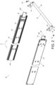
FIG. 2 is an exploded view of the slide rail mechanism according to the first embodiment of the present invention; -
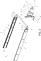
FIG. 3 is a diagram showing the slide rail mechanism with the unlocking handle being located at a second position according to the first embodiment of the present invention. -
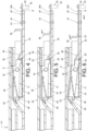
FIG. 4 is a diagram showing a second rail of the slide rail assembly being locked relative to a first rail at a predetermined position with the unlocking handle being located at the first position according to the first embodiment of the present invention; -
FIG. 5 is a diagram showing the second rail of the slide rail assembly being locked relative to the first rail at the predetermined position with the unlocking handle being operated according to the first embodiment of the present invention; -
FIG. 6 is a diagram showing the unlocking handle being located at the second position to unlock the second rail relative to the first rail of the slide rail assembly according to the first embodiment of the present invention; -
FIG. 7 is a diagram showing the slide rail assemblies of the slide rail mechanism being in an extended state according to the first embodiment of the present invention; -
FIG. 8 is a diagram showing a slide rail mechanism with an unlocking handle being located at a first position according to a second embodiment of the present invention; -
FIG. 9 is a diagram showing the slide rail mechanism with the unlocking handle being located at a second position according to the second embodiment of the present invention; and -
FIG. 10 is a diagram showing slide rail assemblies of a slide rail mechanism being in a retracted state according to a third embodiment of the present invention. - As shown in
FIG. 1 ,FIG. 2 andFIG. 3 , aslide rail mechanism 20 comprises a firstslide rail assembly 22, a secondslide rail assembly 24 and anunlocking handle 26 according to a first embodiment of the present invention. The firstslide rail assembly 22 and the secondslide rail assembly 24 have substantially identical structural configuration. Each of theslide rail assemblies first rail 28 and asecond rail 30. Thefirst rail 28 and thesecond rail 30 are longitudinally movable relative to each other, and thesecond rail 30 can be located relative to thefirst rail 28 at a predetermined position R (such as a retracted position, but the present invention is not limited thereto). In the present embodiment, the X-axis is a longitudinal direction (or a length direction of the slide rail), the Y-axis is a transverse direction (or a lateral direction of the slide rail), and the Z-axis is a vertical direction (or a height direction of the slide rail). - Preferably, the
first rail 28 is configured to be fixed to a rack or a cabinet (not shown in figures), and thesecond rail 30 is configured to carry a carried object (not shown in figures). - Preferably, each of the
slide rail assemblies third rail 32 movably mounted between thefirst rail 28 and thesecond rail 30 and configured to extend an opening traveling distance of thesecond rail 30 relative to thefirst rail 28. - The
unlocking handle 26 is movably mounted between the firstslide rail assembly 22 and the secondslide rail assembly 24. For example, theunlocking handle 26 is movable from a first position P1 (as shown inFIG. 1 ) to a second position P2 (as shown inFIG. 3 ). In the present embodiment, theunlocking handle 26 is movably mounted between thesecond rail 30 of the firstslide rail assembly 22 and thesecond rail 30 of the secondslide rail assembly 24, such that theunlocking handle 26 is movable relative to thesecond rail 30 of the firstslide rail assembly 22 and thesecond rail 30 of the secondslide rail assembly 24. - Preferably, each of the
second rails 30 has afront part 30a and arear part 30b, and theunlocking handle 26 is arranged adjacent to thefront parts 30a of the twosecond rails 30. - Preferably, the
unlocking handle 26 comprises two working members (such as a first workingmember 34 and a second working member 36) and alinkage rod 38. The two workingmembers linkage rod 38 is arranged between the two workingmembers members second rail 30 of the firstslide rail assembly 22 and thesecond rail 30 of the secondslide rail assembly 24 respectively. For example, a user can apply a force K along a predetermined direction (such as an upward direction) to thelinkage rod 38 of theunlocking handle 26, such that the two workingmembers unlocking handle 26 are rotated to move from the first position P1 (as shown inFIG. 1 ) to the second position P2 (as shown inFIG 3 ). - Preferably, when the
unlocking handle 26 is located at the first position P1, thelinkage rod 38 of theunlocking handle 26 is at a first height H1 relative to each of theslide rail assemblies 22, 24 (as shown inFIG 1 ). When theunlocking handle 26 is located at the second position P2, thelinkage rod 38 of theunlocking handle 26 is at a second height H2 relative to each of theslide rail assemblies 22, 24 (as shown inFIG 3 ). The second height H2 is different from the first height H1. For example, the second height H2 is higher than the first height H1. In other words, when the unlockinghandle 26 is operated, thelinkage rod 38 of the unlockinghandle 26 is moved to be at different heights relative to each of theslide rail assemblies - Preferably, each of the working
members 34, 36 (such as the first working member 34) comprises afirst part 40 and a second part 42 (as shown inFIG. 2 ). A predetermined distance M is defined between thefirst part 40 and the second part 42 (as shown inFIG. 1 ). Thefirst part 40 is pivotally connected to thesecond rail 30 through a connectingmember 44. Thelinkage rod 38 is connected to thesecond part 42. - Preferably, the unlocking
handle 26 is detachably connected between thesecond rail 30 of the firstslide rail assembly 22 and thesecond rail 30 of the secondslide rail assembly 24. For example, the connectingmember 44 can be a screw, a bolt or the like, but the present invention is not limited thereto. In other words, the unlockinghandle 26 can be detachably connected between thesecond rail 30 of the firstslide rail assembly 22 and thesecond rail 30 of the secondslide rail assembly 24 through the connectingmember 44. - Preferably, each of the working
members 34, 36 (such as the first working member 34) is arranged with a first limitingfeature 46, and each of the second rails 30 (such as thesecond rail 30 of first slide rail assembly 22) is arranged with a second limitingfeature 48. The two workingmembers feature 46 and the second limitingfeature 48. For example, one of the first limitingfeature 46 and the second limitingfeature 48 is an arc hole (or an arc slot), and the other one of the first limitingfeature 46 and the second limitingfeature 48 is a protrusion part extended into a portion of the arc hole (or the arc slot), but the present invention is not limited thereto. - As shown in
FIG. 4 , each of the slide rail assemblies (the firstslide rail assembly 22 and the second slide rail assembly 24) further comprises a lockingmember 31 configured to lock thesecond rail 30 relative to thefirst rail 28 at the predetermined position R. - Preferably, the locking
member 31 is configured to block one edge S of a blockingstructure 50 of thefirst rail 28. In the present embodiment, the blockingstructure 50 is a protruded structure. However, in other alternative embodiments, the blockingstructure 50 can be a recessed (or hole) structure, but the present invention is not limited thereto. Furthermore, the lockingmember 31 is movably mounted to thesecond rail 30. For example, the lockingmember 31 is pivotally connected to thesecond rail 30 through ashaft member 52. - Preferably, each of the slide rail assemblies (the first
slide rail assembly 22 and the second slide rail assembly 24) further comprises anelastic member 54 attached to thesecond rail 30. Theelastic member 54 comprises anelastic part 56 configured to provide an elastic force to the lockingmember 31, such that the lockingmember 31 can be held in a state of blocking the blockingstructure 50 of thefirst rail 28. - Preferably, each of the
slide rail assemblies member 58 movably mounted to thesecond rail 30. For example, the operatingmember 58 is linearly movable relative to thesecond rail 30. A linearly moving direction of the operatingmember 58 is identical to a moving direction (such as a longitudinal direction) of thesecond rail 30. - As shown in
FIG 4, FIG. 5 and FIG. 6 , when the unlockinghandle 26 is moved from the first position P1 (as shown inFIG. 4 ) to the second position P2 (as shown inFIG. 6 ), the unlockinghandle 26 is configured to drive the lockingmember 31 to move in order to unlock thesecond rail 30 relative to thefirst rail 28 at the predetermined location R (as shown inFIG. 6 ), such that thesecond rail 30 can be moved away from the predetermined location R. - Furthermore, when the user applies the force K to the unlocking
handle 26, each of the workingmembers 34, 36 (such as the second working member 36) of the unlockinghandle 26 is rotated and moved from the first position P1 (as shown inFIG. 4 ) to the second position P2 (as shown inFIG. 6 ) by the force K, such that each of the workingmembers 34, 36 (such as the second working member 36) is configured to drive the lockingmember 31 to move through the operatingmember 58 in order to unlock thesecond rail 30 relative to thefirst rail 28 at the predetermined location R. For example, when the user applies the force K to thelinkage rod 38 of the unlockinghandle 26, the two workingmembers handle 26 are rotated around the connectingmember 44 as a rotational axis to be moved from the first position P1 (as shown inFIG. 4 andFIG. 1 ) to the second position P2 (as shown inFIG. 6 andFIG. 3 ), such that each of the two workingmembers member 58 to move linearly. Afirst feature 60 of the operatingmember 58 is configured to be in contact with asecond feature 62 of the locking member 31 (such as a contact between two inclined portions as shown inFIG. 5 , or a contact between an inclined portion and an arc portion, or a contact between two arc portions), such that the operatingmember 58 can easily drive the lockingmember 31 to deflect an angle, in order to disengage the lockingmember 31 from the edge S of the blockingstructure 50 of the first rail 28 (as shown inFIG. 6 ), so as to allow thesecond rail 30 to move relative to thefirst rail 28 along a direction D (such as an opening direction). When the lockingmember 31 is operated to deflect the angle, theelastic part 56 of theelastic member 54 is elastically bent to be in a state of accumulating an elastic force (as shown inFIG. 6 ), and thesecond feature 62 of the lockingmember 31 is moved toward ahole 64 of thesecond rail 30. Moreover, when the lockingmember 31 is driven to deflect the angle, ashoulder part 66 of the lockingmember 31 is configured to abut against a limitingpart 68 of the second rail 24 (as shown inFIG. 6 ). - Moreover, in other alternative embodiments, the operating
member 58 can be omitted. Furthermore, when the unlockinghandle 26 is operated to move from the first position P1 to the second position P2, each of the workingmembers 34, 36 (such as the second working member 36) can directly drive the lockingmember 31 to move in order to unlock thesecond rail 30 relative to thefirst rail 28 at the predetermined position R. - Therefore, the user only needs to apply the force K to the
linkage rod 38 of the unlockinghandle 26 with one hand, such that the unlockinghandle 26 can be moved from the first position P1 to the second position P2 in order to unlock thesecond rails 30 relative to thefirst rails 28 of the two oppositeslide rail assemblies members 34, 36 (such as the first working member 34) can be regarded as a length of a moment arm, such that a labor-saving effect can be achieved when the user applies the force K to thelinkage rod 38 of the unlockinghandle 26 to drive the lockingmember 31 to move. - As shown in
FIG. 7 , when the lockingmember 31 is disengaged from the blockingstructure 50 of thefirst rail 28, thesecond rail 30 can be moved away from the predetermined position R relative to thefirst rail 28, such that both thesecond rail 30 and thethird rail 32 are movable relative to thefirst rail 28 along the direction D to make each of theslide rail assemblies linkage rod 38 of the unlockinghandle 26, the two workingmembers handle 26 return to the first position P1 (as shown inFigure 7 ) from the second position P2 (please refer toFIG. 3 ). -
FIG. 8 andFIG. 9 are diagrams showing aslide rail mechanism 200 according to a second embodiment of the present invention. In the first embodiment, the unlockinghandle 26 of theslide rail mechanism 20 is moved through rotation of the workingmember 34. A main difference between the second embodiment and the first embodiment is that an unlockinghandle 202 of theslide rail mechanism 200 of the second embodiment can be linearly (or longitudinally) moved from a first position P1' (as shown inFIG. 8 ) to a second position P2' (as shown inFIG. 9 ). - Furthermore, one of a
second rail 204 and the unlockinghandle 202 of each of the slide rail assemblies (a firstslide rail assembly 203 and a second slide rail assembly 205) comprises a first predetermined feature 206 (such as a longitudinal groove or a longitudinal hole), and the other one of thesecond rail 204 and the unlockinghandle 202 comprises a second predetermined feature 208 (such as a protrusion or an object similar to the connectingmember 44, which can be inserted into a portion of the longitudinal slot or longitudinal hole). Through interaction between the firstpredetermined feature 206 and the secondpredetermined feature 208, the unlockinghandle 202 can be linearly moved from the first position P1' (as shown inFIG. 8 ) to the second position P2' (as shown inFIG. 9 ) along a linear direction L, so as to provide a driving force F' to drive the operatingmember 210 to move the lockingmember 212, in order to disengage the lockingmember 212 from a blockingstructure 216 of the first rail 214 (as shown inFIG. 9 ), thus thesecond rail 204 can be moved away from the predetermined position R' relative to thefirst rail 214. The linear direction L is identical to a moving direction of thesecond rail 204. For example, both of the linear direction L and the moving direction of thesecond rail 204 are longitudinal directions. In other words, the linear direction L is substantially parallel to the moving direction of thesecond rail 204. Moreover, configuration of the lockingmember 212 locking thesecond rail 204 relative to thefirst rail 214 of the second embodiment is identical to that of the first embodiment. For simplification, no further illustration is provided. -
FIG. 10 is a diagram showing aslide rail mechanism 300 according to a third embodiment of the present invention. In the first embodiment, the unlockinghandle 26 of theslide rail mechanism 20 is movably mounted between thesecond rail 30 of the firstslide rail assembly 22 and thesecond rail 30 of the secondslide rail assembly 24. A main difference between the third second embodiment and the first embodiment is that an unlockinghandle 302 of theslide rail mechanism 300 of the third embodiment is movably mounted to a carriedobject 310 mounted between asecond rail 306 of the firstslide rail assembly 304 and asecond rail 306 of the secondslide rail assembly 308. - Furthermore, the
first rail 312 of each of theslide rail assemblies second rail 306 of each of theslide rail assemblies object 310. Each of workingmembers 314 comprises a first part and a second part. The first part is pivotally connected to the carriedobject 310 through a connectingmember 320. The connectingmember 320 can be a screw, a bolt or the like, but the present invention is not limited thereto. Alinkage rod 322 is connected to the second parts of the workingmembers 314. - According to such configuration, the user can also apply a force to drive the unlocking
handle 302 to move (for example, rotate or pivot) from a first position P1" to a second position P2" in order to unlock thesecond rails 306 relative to thefirst rails 312 of the two oppositeslide rail assemblies - In addition to the unlocking
handle 202 of theslide rail mechanism 200 of the second embodiment being mounted to a slide rail in a linearly movable manner, it is also feasible to mount the unlocking handle to a carried object mounted between the second rail of the first slide rail assembly and the second rail of the second slide rail assembly in a linearly movable manner. According to such configuration, when the unlocking handle is linearly moved from the first position to the second position relative to the second rail (or the carried object), the locking member can be driven to move in order to unlock the second rail relative to the first rail at the predetermined position. - Therefore, the slide rail mechanism and the slide rail assemblies thereof according to the embodiments of the present invention have the following technical features:
- 1. The unlocking handle 26 (202) can be mounted to the slide rail; or the unlocking
handle 302 can be mounted to the carriedobject 310. - 2. The user only needs to apply the force to the unlocking
handle handle - 3. The predetermined distance M of each of the working members (such as the first working member 34) can be regarded as a length of a moment arm, such that a labor-saving effect can be achieved when the user applies the force K to the
linkage rod 38 of the unlockinghandle 26 to drive the lockingmember 31 to move. - 4. The unlocking
handle second rail slide rail assembly second rail slide rail assembly 24, 205 (or the unlockinghandle 302 is detachably mounted to the carriedobject 310 mounted between thesecond rail 306 of the firstslide rail assembly 304 and thesecond rail 306 of the second slide rail assembly 308). In other words, the user can install the unlockinghandle - 5. When the
second rail first rail second rail handle
Claims (15)
- A slide rail mechanism (20, 200, 300), comprising:a first slide rail assembly (22, 203, 304) and a second slide rail assembly (24, 205, 308), each of the first and second slide rail assemblies (22, 203, 304) (24, 205, 308) comprising a first rail (28, 214, 312) and a second rail (30, 204, 306) movable relative to each other, and a locking member (31, 212) configured to lock the second rail (30, 204, 306) relative to the first rail (28, 214, 312) at a predetermined position; andcharacterized by:an unlocking handle (26, 202, 302) movably mounted between the first slide rail assembly (22, 203, 304) and the second slide rail assembly (24, 205, 308);wherein when the unlocking handle (26, 202, 302) is moved from a first position to a second position, the unlocking handle (26, 202, 302) is configured to drive the locking member (31, 212) to move in order to unlock the second rail (30, 204, 306) relative to the first rail (28, 214, 312) at the predetermined position.
- The slide rail mechanism of claim 1, characterized in that the unlocking handle (26, 202, 302) is movably mounted between the second rail (30, 204, 306) of the first slide rail assembly (22, 203, 304) and the second rail (30, 204, 306) of the second slide rail assembly (24, 205, 308).
- The slide rail mechanism of claim 2, characterized in that the unlocking handle (302) is movably mounted on a carried object (310) mounted between the second rail (306) of the first slide rail assembly (304) and the second rail (306) of the second slide rail assembly (308).
- The slide rail mechanism of claim 2, characterized in that the unlocking handle (26, 202, 302) is detachably connected between the second rail (30, 204, 306) of the first slide rail assembly (22, 203, 304) and the second rail (30, 204, 306) of the second slide rail assembly (24, 205, 308).
- The slide rail mechanism of any of claims 2-4, characterized in that the unlocking handle (26, 302) comprises two working members (34, 36, 314) and a linkage rod (38, 322), the linkage rod (38, 322) is arranged between the two working members (34, 36, 314), and the two working members (34, 36, 314) are rotatably connected to the second rail (30, 306) of the first slide rail assembly (22, 304) and the second rail (30, 306) of the second slide rail assembly (24, 308) respectively.
- The slide rail mechanism of claim 5, characterized in that each of the working members (34, 36, 314) comprises a first part (40) and a second part (42), a predetermined distance is defined between the first part (40) and the second part (42), the first part (40) is pivotally connected to the second rail (30, 306) through a connecting member (44, 320), and the linkage rod (38, 322) is connected to the second part (42); wherein each of the working members (34, 36, 314) is arranged with a first limiting feature (46), and each of the second rails (30, 306) is arranged with a second limiting feature (48); wherein the two working members (34, 36, 314) are configured to rotate within a limited range through interaction between the first limiting feature (46) and the second limiting feature (48).
- The slide rail mechanism of claim 6, characterized in that each of the first and second slide rail assemblies (22, 24, 304, 308) further comprises an operating member (58); wherein when a force is applied to the linkage rod (38, 322) of the unlocking handle (26, 302), each of the working members (34, 36, 314) of the unlocking handle (26, 302) is rotated from the first position to the second position in order to drive the locking member (31) to move through the operating member (58); wherein the operating member (58) is linearly movable relative to the second rail (30, 306).
- The slide rail mechanism of any of claims 5-7 characterized in that when the unlocking handle (26, 302) is located at the first position, the linkage rod (38, 322) of the unlocking handle (26, 302) is located at a first height relative to each of the first and second slide rail assemblies (22, 24, 304, 308); wherein when the unlocking handle (26, 302) is located at the second position, the linkage rod (38, 322) of the unlocking handle (26, 302) is located at a second height different from the first height relative to each of the first and second slide rail assemblies (22, 24, 304, 308).
- The slide rail mechanism of claim 1, characterized in that the unlocking handle (202) is configured to be linearly moved from the first position to the second position.
- A slide rail assembly (22, 24, 203, 205, 304, 308), comprising:a first rail (28, 214, 312);a second rail (30, 204, 306) movable relative to the first rail (28, 214, 312);a locking member (31, 212) configured to lock the second rail (30, 204, 306) relative to the first rail (28, 214, 312) at a retracted position; andcharacterized by:an unlocking handle (26, 202, 302) movable relative to the second rail (30, 204, 306);wherein when the unlocking handle (26, 202, 302) is moved from a first position to a second position, the unlocking handle (26, 202, 302) is configured to drive the locking member (31, 212) to move in order to unlock the second rail (30, 204, 306) relative to the first rail (28, 214, 312) at the retracted position, such that the second rail (30, 204, 306) is able to move away from the retracted position.
- The slide rail assembly of claim 10, characterized in that the unlocking handle (26, 202) is detachably connected to the second rail (30, 204).
- The slide rail assembly of claim 10 or 11, characterized in that the unlocking handle (26) comprises a working member (34, 36) and a linkage rod (38), the linkage rod (38) is arranged on the working member (34, 36), and the working member (34, 36) is rotatably connected to the second rail (30); wherein the working member (34, 36) comprises a first part (40) and a second part (42), a predetermined distance is defined between the first part (40) and the second part (42), the first part (40) is pivotally connected to the second rail (30) through a connecting member (44), and the linkage rod (38) is connected to the second part (42); wherein the working member (34, 36) is arranged with a first limiting feature (46), and the second rail (30) is arranged with a second limiting feature (48); wherein the working member (34, 36) is configured to rotate within a limited range through interaction between the first limiting feature (46) and the second limiting feature (48) .
- The slide rail assembly of claim 12, further characterized by an operating member (58); wherein when a force is applied to the linkage rod (38) of the unlocking handle (26), the working member (34, 36) of the unlocking handle (26) is rotated from the first position to the second position in order to drive the locking member (31) to move through the operating member (58); wherein the operating member (58) is linearly movable relative to the second rail (30).
- The slide rail assembly of claim 12 or 13, characterized in that when the unlocking handle (26) is located at the first position, the linkage rod (38) of the unlocking handle (26) is located at a first height relative to the slide rail assembly (22, 24); wherein when the unlocking handle (26) is located at the second position, the linkage rod (38) of the unlocking handle (26) is located at a second height different from the first height relative to the slide rail assembly (22, 24).
- The slide rail assembly of claim 10, characterized in that the unlocking handle (202) is configured to be linearly moved from the first position to the second position.
Applications Claiming Priority (1)
| Application Number | Priority Date | Filing Date | Title |
|---|---|---|---|
| TW111147682A TWI856449B (en) | 2022-12-09 | 2022-12-09 | Slide rail mechanism and slide rail assembly thereof |
Publications (2)
| Publication Number | Publication Date |
|---|---|
| EP4381999A1 true EP4381999A1 (en) | 2024-06-12 |
| EP4381999B1 EP4381999B1 (en) | 2025-08-13 |
Family
ID=86609683
Family Applications (1)
| Application Number | Title | Priority Date | Filing Date |
|---|---|---|---|
| EP23176032.3A Active EP4381999B1 (en) | 2022-12-09 | 2023-05-30 | Slide rail mechanism and slide rail assembly thereof |
Country Status (4)
| Country | Link |
|---|---|
| US (1) | US12440025B2 (en) |
| EP (1) | EP4381999B1 (en) |
| JP (1) | JP7718640B2 (en) |
| TW (1) | TWI856449B (en) |
Families Citing this family (5)
| Publication number | Priority date | Publication date | Assignee | Title |
|---|---|---|---|---|
| US12585313B2 (en) * | 2022-01-10 | 2026-03-24 | Wistron Corporation | Holding seat thereof |
| TR2022013302A2 (en) * | 2022-08-24 | 2024-03-21 | Tusas Tuerk Havacilik Ve Uzay Sanayii Anonim Sirketi | A door lock mechanism. |
| TWI847910B (en) * | 2023-11-09 | 2024-07-01 | 川湖科技股份有限公司 | Slide rail assembly |
| USD1058357S1 (en) * | 2024-06-18 | 2025-01-21 | Changzhou Joshua Home Furnishing Co., Ltd. | Plastic guide rail |
| TWI907254B (en) * | 2025-01-20 | 2025-12-01 | 南俊國際股份有限公司 | Locking device and its slide rail assembly and the operation method of the slide rail assembly |
Citations (6)
| Publication number | Priority date | Publication date | Assignee | Title |
|---|---|---|---|---|
| US10004331B2 (en) | 2010-03-19 | 2018-06-26 | Austin Hardware & Supply Inc. | Drawer release |
| US20190231071A1 (en) * | 2018-01-30 | 2019-08-01 | Austin Hardware And Supply, Inc. | Universal drawer slide |
| US10443271B1 (en) * | 2018-10-29 | 2019-10-15 | The Cornwell Quality Tools Company | Drawer latch system |
| US20190352938A1 (en) * | 2018-05-21 | 2019-11-21 | Allegis Corporation | Hybrid drawer handle and release mechanism |
| WO2021146355A1 (en) | 2020-01-13 | 2021-07-22 | Accuride International Inc. | Rotational bar for drawer slide latch operation |
| US20220312959A1 (en) * | 2016-07-14 | 2022-10-06 | Dejana Truck And Utility Equipment Co., Inc. | Shelving systems |
Family Cites Families (17)
| Publication number | Priority date | Publication date | Assignee | Title |
|---|---|---|---|---|
| US5033805A (en) * | 1990-05-08 | 1991-07-23 | General Devices Co., Inc. | Drawer slide assembly with releasable lock mechanism |
| US5292191A (en) * | 1991-11-25 | 1994-03-08 | Snap-On Tools Corporation | Latch mechanism for a cabinet drawer |
| US5417490A (en) * | 1993-03-29 | 1995-05-23 | General Devices Co., Inc. | Telescoping slide assembly |
| TW489618U (en) * | 2001-01-05 | 2002-06-01 | King Slide Works Co Ltd | Front-pulling type latch mechanism for rail |
| WO2005044046A1 (en) * | 2003-01-10 | 2005-05-19 | Alfit Ag | Automatic retraction mechanism for drawer pull-out guides |
| CH703948B1 (en) * | 2003-02-19 | 2012-04-30 | Lista Europ Holding Ag | Grip bar for a drawer, in particular for a drawer of storage and resource means. |
| TWM341454U (en) * | 2007-10-18 | 2008-10-01 | Kuo-Chan Weng | Stopping structure for preventing drawer sliding |
| TWM379377U (en) * | 2009-11-25 | 2010-05-01 | ting-yu Zhang | Latching structure of cabinet drawer |
| US8528998B2 (en) * | 2010-05-25 | 2013-09-10 | Accuride International, Inc. | Adjustable detent retention system and method |
| US9010830B2 (en) * | 2013-06-04 | 2015-04-21 | Charles L. Hanley | Shelving systems |
| US9181731B2 (en) * | 2013-10-17 | 2015-11-10 | Larry Mitchell Grela | Drawer latch assembly and a toolbox assembly |
| CN108030294B (en) * | 2018-01-19 | 2024-03-15 | 广东东泰五金精密制造有限公司 | Sliding rail locking and dismounting structure |
| TWI659712B (en) * | 2018-04-02 | 2019-05-21 | 川湖科技股份有限公司 | Slide rail assembly |
| CN212837220U (en) * | 2020-07-17 | 2021-03-30 | 四川爱创科技有限公司 | Intelligent terminal equipment lock and intelligent terminal cabinet |
| CN215169084U (en) * | 2020-11-30 | 2021-12-14 | 雅固拉国际精密工业(苏州)有限公司 | Pivoting mechanism and cabinet |
| TWI793684B (en) * | 2021-07-20 | 2023-02-21 | 緯創資通股份有限公司 | Server apparatus and tray mechanism thereof |
| US12610483B2 (en) * | 2021-10-22 | 2026-04-21 | EMC IP Holding Company, LLC | Chassis node coupling system |
-
2022
- 2022-12-09 TW TW111147682A patent/TWI856449B/en active
-
2023
- 2023-04-27 US US18/307,955 patent/US12440025B2/en active Active
- 2023-05-30 EP EP23176032.3A patent/EP4381999B1/en active Active
- 2023-07-10 JP JP2023112768A patent/JP7718640B2/en active Active
Patent Citations (6)
| Publication number | Priority date | Publication date | Assignee | Title |
|---|---|---|---|---|
| US10004331B2 (en) | 2010-03-19 | 2018-06-26 | Austin Hardware & Supply Inc. | Drawer release |
| US20220312959A1 (en) * | 2016-07-14 | 2022-10-06 | Dejana Truck And Utility Equipment Co., Inc. | Shelving systems |
| US20190231071A1 (en) * | 2018-01-30 | 2019-08-01 | Austin Hardware And Supply, Inc. | Universal drawer slide |
| US20190352938A1 (en) * | 2018-05-21 | 2019-11-21 | Allegis Corporation | Hybrid drawer handle and release mechanism |
| US10443271B1 (en) * | 2018-10-29 | 2019-10-15 | The Cornwell Quality Tools Company | Drawer latch system |
| WO2021146355A1 (en) | 2020-01-13 | 2021-07-22 | Accuride International Inc. | Rotational bar for drawer slide latch operation |
Also Published As
| Publication number | Publication date |
|---|---|
| JP7718640B2 (en) | 2025-08-05 |
| US12440025B2 (en) | 2025-10-14 |
| US20240188715A1 (en) | 2024-06-13 |
| TW202423344A (en) | 2024-06-16 |
| EP4381999B1 (en) | 2025-08-13 |
| TWI856449B (en) | 2024-09-21 |
| JP2024083224A (en) | 2024-06-20 |
Similar Documents
| Publication | Publication Date | Title |
|---|---|---|
| EP4381999B1 (en) | Slide rail mechanism and slide rail assembly thereof | |
| CN101929271B (en) | The handle of sliding door and door bolt | |
| US20240076907A1 (en) | Multi-point exit device | |
| EP3275338B1 (en) | Slide rail assembly | |
| US8398126B2 (en) | Multipoint lock mechanism | |
| EP1842995A1 (en) | Side lock assembly for storage bin | |
| EP1854943A1 (en) | Opening/closing lock device for glove box | |
| EP3886546B1 (en) | Slide rail assembly | |
| EP3112217A1 (en) | A load carrier comprising a lock arrangement | |
| CN110847703B (en) | Unlocking method of lock | |
| EP4548808A1 (en) | Slide rail assembly | |
| CN210714156U (en) | Lock and equipment with lock | |
| EP4563040B1 (en) | Slide rail assembly | |
| US12604981B2 (en) | Slide rail assembly | |
| CN118203207A (en) | Slide rail mechanism and slide rail assembly | |
| EP4563039B1 (en) | Slide rail assembly | |
| CN115604966B (en) | Top cover components and servers | |
| US20260117569A1 (en) | Handle and sliding rail assembly with the handle | |
| CN222576384U (en) | Handle lock suitable for padlock | |
| CN114554772B (en) | Slide rail assembly | |
| CN120018435A (en) | Slide rail assembly | |
| CN121751540A (en) | Lock assembly and LED display device having the same | |
| JP2021042531A (en) | Locking device rod stroke extension device | |
| HK1028078B (en) | Cremone lock assembly of pull and rotation type |
Legal Events
| Date | Code | Title | Description |
|---|---|---|---|
| PUAI | Public reference made under article 153(3) epc to a published international application that has entered the european phase |
Free format text: ORIGINAL CODE: 0009012 |
|
| STAA | Information on the status of an ep patent application or granted ep patent |
Free format text: STATUS: REQUEST FOR EXAMINATION WAS MADE |
|
| 17P | Request for examination filed |
Effective date: 20240131 |
|
| AK | Designated contracting states |
Kind code of ref document: A1 Designated state(s): AL AT BE BG CH CY CZ DE DK EE ES FI FR GB GR HR HU IE IS IT LI LT LU LV MC ME MK MT NL NO PL PT RO RS SE SI SK SM TR |
|
| STAA | Information on the status of an ep patent application or granted ep patent |
Free format text: STATUS: EXAMINATION IS IN PROGRESS |
|
| 17Q | First examination report despatched |
Effective date: 20241209 |
|
| GRAP | Despatch of communication of intention to grant a patent |
Free format text: ORIGINAL CODE: EPIDOSNIGR1 |
|
| STAA | Information on the status of an ep patent application or granted ep patent |
Free format text: STATUS: GRANT OF PATENT IS INTENDED |
|
| INTG | Intention to grant announced |
Effective date: 20250516 |
|
| GRAS | Grant fee paid |
Free format text: ORIGINAL CODE: EPIDOSNIGR3 |
|
| GRAA | (expected) grant |
Free format text: ORIGINAL CODE: 0009210 |
|
| STAA | Information on the status of an ep patent application or granted ep patent |
Free format text: STATUS: THE PATENT HAS BEEN GRANTED |
|
| AK | Designated contracting states |
Kind code of ref document: B1 Designated state(s): AL AT BE BG CH CY CZ DE DK EE ES FI FR GB GR HR HU IE IS IT LI LT LU LV MC ME MK MT NL NO PL PT RO RS SE SI SK SM TR |
|
| REG | Reference to a national code |
Ref country code: GB Ref legal event code: FG4D |
|
| REG | Reference to a national code |
Ref country code: CH Ref legal event code: EP |
|
| REG | Reference to a national code |
Ref country code: DE Ref legal event code: R096 Ref document number: 602023005620 Country of ref document: DE |
|
| REG | Reference to a national code |
Ref country code: IE Ref legal event code: FG4D |
|
| REG | Reference to a national code |
Ref country code: NL Ref legal event code: MP Effective date: 20250813 |
|
| PG25 | Lapsed in a contracting state [announced via postgrant information from national office to epo] |
Ref country code: IS Free format text: LAPSE BECAUSE OF FAILURE TO SUBMIT A TRANSLATION OF THE DESCRIPTION OR TO PAY THE FEE WITHIN THE PRESCRIBED TIME-LIMIT Effective date: 20251213 |
|
| PG25 | Lapsed in a contracting state [announced via postgrant information from national office to epo] |
Ref country code: NO Free format text: LAPSE BECAUSE OF FAILURE TO SUBMIT A TRANSLATION OF THE DESCRIPTION OR TO PAY THE FEE WITHIN THE PRESCRIBED TIME-LIMIT Effective date: 20251113 |
|
| REG | Reference to a national code |
Ref country code: LT Ref legal event code: MG9D |
|
| PG25 | Lapsed in a contracting state [announced via postgrant information from national office to epo] |
Ref country code: PT Free format text: LAPSE BECAUSE OF FAILURE TO SUBMIT A TRANSLATION OF THE DESCRIPTION OR TO PAY THE FEE WITHIN THE PRESCRIBED TIME-LIMIT Effective date: 20251215 |
|
| PG25 | Lapsed in a contracting state [announced via postgrant information from national office to epo] |
Ref country code: FI Free format text: LAPSE BECAUSE OF FAILURE TO SUBMIT A TRANSLATION OF THE DESCRIPTION OR TO PAY THE FEE WITHIN THE PRESCRIBED TIME-LIMIT Effective date: 20250813 |
|
| PG25 | Lapsed in a contracting state [announced via postgrant information from national office to epo] |
Ref country code: HR Free format text: LAPSE BECAUSE OF FAILURE TO SUBMIT A TRANSLATION OF THE DESCRIPTION OR TO PAY THE FEE WITHIN THE PRESCRIBED TIME-LIMIT Effective date: 20250813 Ref country code: NL Free format text: LAPSE BECAUSE OF FAILURE TO SUBMIT A TRANSLATION OF THE DESCRIPTION OR TO PAY THE FEE WITHIN THE PRESCRIBED TIME-LIMIT Effective date: 20250813 |
|
| PG25 | Lapsed in a contracting state [announced via postgrant information from national office to epo] |
Ref country code: GR Free format text: LAPSE BECAUSE OF FAILURE TO SUBMIT A TRANSLATION OF THE DESCRIPTION OR TO PAY THE FEE WITHIN THE PRESCRIBED TIME-LIMIT Effective date: 20251114 |
|
| PG25 | Lapsed in a contracting state [announced via postgrant information from national office to epo] |
Ref country code: SE Free format text: LAPSE BECAUSE OF FAILURE TO SUBMIT A TRANSLATION OF THE DESCRIPTION OR TO PAY THE FEE WITHIN THE PRESCRIBED TIME-LIMIT Effective date: 20250813 |
|
| PG25 | Lapsed in a contracting state [announced via postgrant information from national office to epo] |
Ref country code: LV Free format text: LAPSE BECAUSE OF FAILURE TO SUBMIT A TRANSLATION OF THE DESCRIPTION OR TO PAY THE FEE WITHIN THE PRESCRIBED TIME-LIMIT Effective date: 20250813 |
|
| PG25 | Lapsed in a contracting state [announced via postgrant information from national office to epo] |
Ref country code: PL Free format text: LAPSE BECAUSE OF FAILURE TO SUBMIT A TRANSLATION OF THE DESCRIPTION OR TO PAY THE FEE WITHIN THE PRESCRIBED TIME-LIMIT Effective date: 20250813 Ref country code: BG Free format text: LAPSE BECAUSE OF FAILURE TO SUBMIT A TRANSLATION OF THE DESCRIPTION OR TO PAY THE FEE WITHIN THE PRESCRIBED TIME-LIMIT Effective date: 20250813 |
|
| PG25 | Lapsed in a contracting state [announced via postgrant information from national office to epo] |
Ref country code: RS Free format text: LAPSE BECAUSE OF FAILURE TO SUBMIT A TRANSLATION OF THE DESCRIPTION OR TO PAY THE FEE WITHIN THE PRESCRIBED TIME-LIMIT Effective date: 20251113 |
|
| PG25 | Lapsed in a contracting state [announced via postgrant information from national office to epo] |
Ref country code: ES Free format text: LAPSE BECAUSE OF FAILURE TO SUBMIT A TRANSLATION OF THE DESCRIPTION OR TO PAY THE FEE WITHIN THE PRESCRIBED TIME-LIMIT Effective date: 20250813 |
|
| REG | Reference to a national code |
Ref country code: AT Ref legal event code: MK05 Ref document number: 1823736 Country of ref document: AT Kind code of ref document: T Effective date: 20250813 |
|
| PG25 | Lapsed in a contracting state [announced via postgrant information from national office to epo] |
Ref country code: SM Free format text: LAPSE BECAUSE OF FAILURE TO SUBMIT A TRANSLATION OF THE DESCRIPTION OR TO PAY THE FEE WITHIN THE PRESCRIBED TIME-LIMIT Effective date: 20250813 |
|
| PG25 | Lapsed in a contracting state [announced via postgrant information from national office to epo] |
Ref country code: DK Free format text: LAPSE BECAUSE OF FAILURE TO SUBMIT A TRANSLATION OF THE DESCRIPTION OR TO PAY THE FEE WITHIN THE PRESCRIBED TIME-LIMIT Effective date: 20250813 |
|
| PGFP | Annual fee paid to national office [announced via postgrant information from national office to epo] |
Ref country code: IE Payment date: 20260330 Year of fee payment: 4 |
|
| PG25 | Lapsed in a contracting state [announced via postgrant information from national office to epo] |
Ref country code: AT Free format text: LAPSE BECAUSE OF FAILURE TO SUBMIT A TRANSLATION OF THE DESCRIPTION OR TO PAY THE FEE WITHIN THE PRESCRIBED TIME-LIMIT Effective date: 20250813 |
|
| PG25 | Lapsed in a contracting state [announced via postgrant information from national office to epo] |
Ref country code: IT Free format text: LAPSE BECAUSE OF FAILURE TO SUBMIT A TRANSLATION OF THE DESCRIPTION OR TO PAY THE FEE WITHIN THE PRESCRIBED TIME-LIMIT Effective date: 20250813 |
|
| PG25 | Lapsed in a contracting state [announced via postgrant information from national office to epo] |
Ref country code: CZ Free format text: LAPSE BECAUSE OF FAILURE TO SUBMIT A TRANSLATION OF THE DESCRIPTION OR TO PAY THE FEE WITHIN THE PRESCRIBED TIME-LIMIT Effective date: 20250813 |
|
| PG25 | Lapsed in a contracting state [announced via postgrant information from national office to epo] |
Ref country code: EE Free format text: LAPSE BECAUSE OF FAILURE TO SUBMIT A TRANSLATION OF THE DESCRIPTION OR TO PAY THE FEE WITHIN THE PRESCRIBED TIME-LIMIT Effective date: 20250813 Ref country code: SK Free format text: LAPSE BECAUSE OF FAILURE TO SUBMIT A TRANSLATION OF THE DESCRIPTION OR TO PAY THE FEE WITHIN THE PRESCRIBED TIME-LIMIT Effective date: 20250813 |