EP4381991A1 - A cosmetic packaging bottle restricting backflow - Google Patents
A cosmetic packaging bottle restricting backflow Download PDFInfo
- Publication number
- EP4381991A1 EP4381991A1 EP23150003.4A EP23150003A EP4381991A1 EP 4381991 A1 EP4381991 A1 EP 4381991A1 EP 23150003 A EP23150003 A EP 23150003A EP 4381991 A1 EP4381991 A1 EP 4381991A1
- Authority
- EP
- European Patent Office
- Prior art keywords
- liquid discharge
- packaging bottle
- flow restriction
- return valve
- discharge head
- Prior art date
- Legal status (The legal status is an assumption and is not a legal conclusion. Google has not performed a legal analysis and makes no representation as to the accuracy of the status listed.)
- Granted
Links
Images


Classifications
-
- A—HUMAN NECESSITIES
- A45—HAND OR TRAVELLING ARTICLES
- A45D—HAIRDRESSING OR SHAVING EQUIPMENT; EQUIPMENT FOR COSMETICS OR COSMETIC TREATMENTS, e.g. FOR MANICURING OR PEDICURING
- A45D34/00—Containers or accessories specially adapted for handling liquid toiletry or cosmetic substances, e.g. perfumes
- A45D34/04—Appliances specially adapted for applying liquid, e.g. using roller or ball
-
- A—HUMAN NECESSITIES
- A45—HAND OR TRAVELLING ARTICLES
- A45D—HAIRDRESSING OR SHAVING EQUIPMENT; EQUIPMENT FOR COSMETICS OR COSMETIC TREATMENTS, e.g. FOR MANICURING OR PEDICURING
- A45D34/00—Containers or accessories specially adapted for handling liquid toiletry or cosmetic substances, e.g. perfumes
-
- B—PERFORMING OPERATIONS; TRANSPORTING
- B65—CONVEYING; PACKING; STORING; HANDLING THIN OR FILAMENTARY MATERIAL
- B65D—CONTAINERS FOR STORAGE OR TRANSPORT OF ARTICLES OR MATERIALS, e.g. BAGS, BARRELS, BOTTLES, BOXES, CANS, CARTONS, CRATES, DRUMS, JARS, TANKS, HOPPERS, FORWARDING CONTAINERS; ACCESSORIES, CLOSURES, OR FITTINGS THEREFOR; PACKAGING ELEMENTS; PACKAGES
- B65D35/00—Pliable tubular containers adapted to be permanently or temporarily deformed to expel contents, e.g. collapsible tubes for toothpaste or other plastic or semi-liquid material; Holders therefor
- B65D35/44—Closures
- B65D35/46—Closures with valves
-
- B—PERFORMING OPERATIONS; TRANSPORTING
- B65—CONVEYING; PACKING; STORING; HANDLING THIN OR FILAMENTARY MATERIAL
- B65D—CONTAINERS FOR STORAGE OR TRANSPORT OF ARTICLES OR MATERIALS, e.g. BAGS, BARRELS, BOTTLES, BOXES, CANS, CARTONS, CRATES, DRUMS, JARS, TANKS, HOPPERS, FORWARDING CONTAINERS; ACCESSORIES, CLOSURES, OR FITTINGS THEREFOR; PACKAGING ELEMENTS; PACKAGES
- B65D47/00—Closures with filling and discharging, or with discharging, devices
- B65D47/04—Closures with discharging devices other than pumps
- B65D47/20—Closures with discharging devices other than pumps comprising hand-operated members for controlling discharge
- B65D47/2018—Closures with discharging devices other than pumps comprising hand-operated members for controlling discharge comprising a valve or like element which is opened or closed by deformation of the container or closure
- B65D47/2031—Closures with discharging devices other than pumps comprising hand-operated members for controlling discharge comprising a valve or like element which is opened or closed by deformation of the container or closure the element being formed by a slit, narrow opening or constrictable spout, the size of the outlet passage being able to be varied by increasing or decreasing the pressure
Definitions
- the invention relates to the field of cosmetic packaging bottles, and in particular, to a cosmetic packaging bottle restricting backflow.
- the bottle seat outlet of the soft tube packaging bottle is usually equipped with a massage head, and accessories such as heating and vibration are placed in the bottle seat to assist in massage absorption. Therefore, the bottle seat outlet has a long passage, and lotion from the massage head tends to flow back into the passage when used, and lotions may be sucked back into the bottle by the soft tube packaging bottle, resulting in contamination of the cosmetic lotion inside the bottle by microorganisms or bacteria.
- the invention provides a cosmetic packaging bottle restricting backflow, with a one-way flow restriction function, so that the contents of the soft tube packaging bottle are squeezed in one direction and cannot flow back, preventing the contents from flowing back and causing contamination of the contents of the soft tube packaging bottle.
- a cosmetic packaging bottle restricting backflow including a soft tube packaging bottle and a liquid discharge head, and also including a non-return valve sheet, which is placed within the liquid discharge head.
- the non-return valve sheet has a one-way flow restriction function, so that contents of the soft tube packaging bottle are squeezed out in one direction and cannot flow back.
- a middle part of the non-return valve sheet is provided with a cross-shaped cutout, the non-return valve sheet is normally closed, the non-return valve sheet is squeezed by the contents to open upward and discharge the contents.
- the flow restriction seat is placed on the mouth of the soft tube packaging bottle, and the non-return valve sheet is attached to the upper part of the flow restriction seat, and the flow restriction channel is placed in the flow restriction seat; the bottom of the liquid discharge head has a concave cavity, and the liquid discharge head is placed on the flow restriction seat and pressed against the circumference of the non-return valve sheet, and a liquid discharge cavity is placed in a middle part of the liquid discharge head, and the cross-shaped cutout of the non-return valve sheet can be opened in the direction of the liquid discharge cavity.
- At least one section of the flow restriction channel of the flow restriction seat is a non-linear channel.
- the bottom of the flow restriction seat is a concave cavity structure
- the flow restriction channel includes a through-port placed in the side wall of the flow restriction seat, a side groove channel placed between the outer side wall of the flow restriction seat and the liquid discharge head, and an upper groove channel placed in the upper end of the flow restriction seat; the through-port, side groove channel, and upper groove channel are connected to each other in turn.
- the side groove channel is a spiral structure.
- the spiral flow restriction channel makes contents enter from the side and exit from the upper part, which can limit the outflow rate of contents, to accurately use the squeeze volume, to prevent contents from splashing and spilling due to excessive force when squeezing, to avoid waste.
- the upper groove channel extends from the middle to the edge and is connected to the side groove channel.
- the upper part of the liquid discharge head is a liquid discharge column, and the inner cavity of the liquid discharge column forms the aforementioned liquid discharge cavity, and the liquid discharge cavity is connected to the outside of the liquid discharge column.
- the mouth of the soft tube packaging bottle is provided with a threaded holder
- the bottom surface of the threaded holder is provided with a limit platform
- a middle part of the limit platform is provided with an opening corresponding to the open concave cavity structure of the bottom surface of the flow restriction seat
- the flow restriction seat and the liquid discharge head are placed inside the threaded holder
- the outer wall of the liquid discharge head is close to the inner wall of the threaded holder.
- it also includes an outer cover, which is screwed to the threaded holder, and a raised plunger is placed in a middle part of the outer cover, and the plunger closes the upper end of the liquid discharge cavity after the outer cover is installed.
- the beneficial effect of the invention is: a cosmetic packaging bottle restricting backflow, with a one-way flow restriction function, so that the contents of the soft tube packaging bottle can be squeezed in one direction and cannot flow back, to prevent the contents of the backflow of the soft tube packaging bottle from causing contamination of the contents.
- the non-return valve sheet has a one-way valve role, the middle is provided with a cross-shaped cutout. The non-return valve sheet is normally closed. When the contents are squeezed out, the non-return valve sheet squeezed by the contents will open upward, the contents are discharged. After the stopping of squeezing, the soft tube packaging bottle has a tendency to reset and will suck back the contents, the contents tend to flow back. At this time, the non-return valve sheet is sucked downward against the upper surface of the flow restriction seat to keep it closed and prevent contents from flowing back.
- the cosmetic packaging bottle restricting backflow consists of a soft tube packaging bottle 1 and a liquid discharge head 2, and a non-return valve sheet 6 is installed in the liquid discharge head 2.
- the non-return valve sheet 6 has a one-way flow restriction function, so that the contents of the soft tube packaging bottle 1 are squeezed out in one direction and cannot flow back, preventing the contents from flowing back and causing contamination of the contents of the soft tube packaging bottle 1.
- a middle part of the non-return valve sheet 6 is provided with a cross-shaped cutout 61, the non-return valve sheet 6 is closed in the normal state, the non-return valve sheet 6 is squeezed by the contents to open upward and discharge the contents.
- the flow restriction seat 4 is placed on the mouth of the soft tube packaging bottle 1, and the non-return valve sheet 6 is attached to the upper part of the flow restriction seat 4, the flow restriction seat 4 is provided with a flow restriction channel, and the non-return valve sheet 6 covers the outlet of the flow restriction channel; the bottom of the liquid discharge head 2 has a concave cavity, and the concave cavity part of the liquid discharge head 2 is placed on the flow restriction seat 4, and the inner wall surface of the concave cavity of the liquid discharge head 2 is close to the outer side wall of the flow restriction seat 4.
- the top surface of the concave cavity of the liquid discharge head 2 is pressed against the circumference of the non-return valve sheet 6, and a liquid discharge cavity 21 is provided in a middle part of the liquid discharge head 2, and the cross-shaped cutout 61 of the non-return valve sheet 6 can be opened in the direction of the liquid discharge cavity 21.
- the outer diameter of the liquid discharge cavity 21 is larger than the flow restriction channel, and the cross-shaped cutout 61 of the non-return valve sheet 6 cannot be opened in the direction of the flow restriction channel, which has a one-way flow restriction effect.
- At least one section of the flow restriction channel of the flow restriction seat 4 is a non-linear channel.
- the process of the contents passing through the flow restriction channel needs to pass through a number of bends, which can slow down the speed of its outflow.
- the bottom of the flow restriction seat 4 is a concave cavity structure
- the flow restriction channel includes a through-port 41 placed in the side wall of the flow restriction seat 4, a side groove channel 42 placed between the outer side wall of the flow restriction seat 4 and the liquid discharge head, and an upper groove channel 43 placed in the upper surface of the flow restriction seat 4; the through-port 41, the side groove channel 42, and the upper groove channel 43 are connected to each other in turn.
- the side groove channel 42 is a spiral structure.
- the side groove channel 42 is a groove structure placed on the side wall of the flow restriction seat 4, which is combined with the inner wall surface of the concave cavity of the liquid discharge head 2 to form a complete threaded pipe type channel.
- the upper groove channel 43 extends from the middle to the edge and is connected to the side groove channel 42.
- the width of the upper groove channel 43 in a groove structure, is much smaller than the outer diameter of the liquid discharge cavity 21.
- the width of the upper groove channel 43 is not wide enough to allow the cross-shaped cutout 61 of the non-return valve sheet 6 to open downward, and when the non-return valve sheet 6 is under suction, the cross-shaped cutout 61 presses downward against the upper surface of the flow restriction seat 4 in a closed state.
- the non-return valve sheet 6 is made of silicone with a hardness of 70 degrees and good flexibility, and the cross-shaped cutout 61 opens and closes reliably.
- the upper part of the liquid discharge head 2 is the liquid discharge column 5, and the inner cavity of the liquid discharge column 5 forms the aforementioned liquid discharge cavity 21, and the liquid discharge cavity 21 is connected to the outside of the liquid discharge column 5.
- the mouth of the soft tube packaging bottle 1 is provided with a threaded holder 11, the bottom surface of the threaded holder 11 is provided with a limit platform 12, and a middle part of the limit platform 12 is provided with an opening 121 corresponding to the open concave cavity structure of the bottom surface of the flow restriction seat 4, and the opening 121 is connected to the flow restriction seat 4 and the soft tube packaging bottle.
- the flow restriction seat 4 and the liquid discharge head 2 are placed inside the threaded holder 11, and the liquid discharge head 2 is placed on the flow restriction seat 4 and then fitted into the threaded holder 11, and the outer wall of the liquid discharge head 2 is tightly pressed against the inner wall of the threaded holder 11.
- a convex ring 22 and a slot 12 are provided between the outer wall of the liquid discharge head 2 and the inner wall of the threaded holder 11.
- the slot 12 and the convex ring 22 are correspondingly clamped to each other for a more stable installation, and the slot 12 and the convex ring 22 have an arc-shaped structure for easy installation.
- FIG. 1 There is an outer cover 3 attached to the outside of the liquid discharge head 2, and the outer cover 3 is screwed to the threaded holder 11.
- a middle part of the outer cover 3 is provided with a raised plunger 31, and after the outer cover 3 is installed, the plunger 31 closes the outlet port at the upper end of the liquid discharge column 51.
- the cross-shaped cutout 61 is in the bonding state, gas on both sides is sealed.
- the pressure in the content squeezing process flushes out the cross-shaped cutout 61, ending its bonding state.
- the contents When the contents are filled, the contents are filled from the bottom of the soft tube packaging bottle 1.
- the time required for the contents to enter the through-hole 41, the side groove channel 42, and then the upper groove channel 43 is greater than the time required for the entire cosmetic can to be completed, so the non-return valve sheet not 6 is opened, and its closed state can maximize the effective isolation of the air on the other side of the non-return valve sheet 6 to avoid direct contact between the cosmetic contents and the air and prevent microbial or bacterial contamination. It prevents microbial or bacterial contamination and effectively protects the quality of cosmetics.
- the groove channel 42 is a semi-circular groove, and the diameter of the groove channel 42 and the through-hole 41 is between 1.3 and 1.34 mm, forming a flow channel with a narrow diameter and a certain resistance.
- the threaded pipe-type channel formed between the groove channel 42 and the liquid discharge head 2 has more than two coils, with a total length of 50.4 mm.
- the length of the upper groove channel 43 is 5.09 mm
- the length of the through-hole 41 is 2.07 mm, i.e., the total length of the flow restriction channel is 57.56 mm
- the length of the threaded pipe channel is similar to the length of the soft tube packaging bottle 1, the contents are filled from the bottom of the soft tube packaging bottle 1, filling the whole soft tube packaging bottle 1 first, and then flowing into the threaded pipe channel.
- the time for the contents to enter the flow restriction channel and reach the non-return valve sheet 6 is much longer than the time to fill the whole soft tube packaging bottle 1, with enough time to adjust or stop filling, so the non-return valve sheet 6 is not open in the filling process, isolating the air on the other side, avoiding direct contact between the cosmetic contents and air, preventing microbial or bacterial contamination and effectively protecting the quality of cosmetics.
- the side groove channel 42 is placed between the outer side wall of the flow restriction seat 4 and the liquid discharge head, and the upper groove channel 43 is placed on the upper surface of the flow restriction seat 4; the through-port 41, the side groove channel 42, and the upper groove channel 43 are connected to each other in turn.
- a cosmetic packaging bottle restricting backflow described in the invention has a one-way flow restriction function, so that the contents of the soft tube packaging bottle 1 are extruded in one direction and cannot flow back, preventing the contents from flowing back and causing contamination of the contents of the soft tube packaging bottle 1.
- the non-return valve sheet 6 has a one-way valve role, the middle is provided with a cross-shaped cutout 61. The non-return valve sheet 6 is normally closed. When the contents are squeezed out, the non-return valve sheet 6 squeezed by the contents will open upward, the contents are discharged. After the stopping of squeezing, the soft tube packaging bottle 1 has a tendency to reset and will suck back the contents, the contents tend to flow back.
- the non-return valve sheet 6 is sucked downward against the upper surface of the flow restriction seat 4 to keep it closed and prevent the contents from flowing back.
- the contents enter from the side and exit from the top, which can limit the outflow rate of the contents, to squeeze accurately and prevent the contents from splashing and spilling due to excessive force during squeezing, to avoid waste.
Landscapes
- Engineering & Computer Science (AREA)
- Mechanical Engineering (AREA)
- Closures For Containers (AREA)
- Containers And Packaging Bodies Having A Special Means To Remove Contents (AREA)
Abstract
Description
- This application claims priority to
Chinese Patent Application 202223284958.7, filed on December 06, 2022 - The invention relates to the field of cosmetic packaging bottles, and in particular, to a cosmetic packaging bottle restricting backflow.
- With the improvement of living standards, more and more people attach importance to skin care and are in need of more volume of cosmetics. There are usually lotion-like and viscous products. Many lotion-like and viscous contents using soft tube packaging bottles. In the usage, contents of cosmetics in the bottle are squeezed out. With the increase in demand for comfort in use, the bottle seat outlet of the soft tube packaging bottle is usually equipped with a massage head, and accessories such as heating and vibration are placed in the bottle seat to assist in massage absorption. Therefore, the bottle seat outlet has a long passage, and lotion from the massage head tends to flow back into the passage when used, and lotions may be sucked back into the bottle by the soft tube packaging bottle, resulting in contamination of the cosmetic lotion inside the bottle by microorganisms or bacteria.
- In order to overcome the aforementioned problems, the invention provides a cosmetic packaging bottle restricting backflow, with a one-way flow restriction function, so that the contents of the soft tube packaging bottle are squeezed in one direction and cannot flow back, preventing the contents from flowing back and causing contamination of the contents of the soft tube packaging bottle.
- The technical solution adopted by the invention to solve the technical problems is: a cosmetic packaging bottle restricting backflow, including a soft tube packaging bottle and a liquid discharge head, and also including a non-return valve sheet, which is placed within the liquid discharge head. The non-return valve sheet has a one-way flow restriction function, so that contents of the soft tube packaging bottle are squeezed out in one direction and cannot flow back.
- Preferably, a middle part of the non-return valve sheet is provided with a cross-shaped cutout, the non-return valve sheet is normally closed, the non-return valve sheet is squeezed by the contents to open upward and discharge the contents. The flow restriction seat is placed on the mouth of the soft tube packaging bottle, and the non-return valve sheet is attached to the upper part of the flow restriction seat, and the flow restriction channel is placed in the flow restriction seat; the bottom of the liquid discharge head has a concave cavity, and the liquid discharge head is placed on the flow restriction seat and pressed against the circumference of the non-return valve sheet, and a liquid discharge cavity is placed in a middle part of the liquid discharge head, and the cross-shaped cutout of the non-return valve sheet can be opened in the direction of the liquid discharge cavity.
- Preferably, at least one section of the flow restriction channel of the flow restriction seat is a non-linear channel.
- Preferably, the bottom of the flow restriction seat is a concave cavity structure, and the flow restriction channel includes a through-port placed in the side wall of the flow restriction seat, a side groove channel placed between the outer side wall of the flow restriction seat and the liquid discharge head, and an upper groove channel placed in the upper end of the flow restriction seat; the through-port, side groove channel, and upper groove channel are connected to each other in turn.
- Preferably, the side groove channel is a spiral structure. The spiral flow restriction channel makes contents enter from the side and exit from the upper part, which can limit the outflow rate of contents, to accurately use the squeeze volume, to prevent contents from splashing and spilling due to excessive force when squeezing, to avoid waste.
- Preferably, the upper groove channel extends from the middle to the edge and is connected to the side groove channel.
- Preferably, the upper part of the liquid discharge head is a liquid discharge column, and the inner cavity of the liquid discharge column forms the aforementioned liquid discharge cavity, and the liquid discharge cavity is connected to the outside of the liquid discharge column.
- Preferably, the mouth of the soft tube packaging bottle is provided with a threaded holder, the bottom surface of the threaded holder is provided with a limit platform, a middle part of the limit platform is provided with an opening corresponding to the open concave cavity structure of the bottom surface of the flow restriction seat, the flow restriction seat and the liquid discharge head are placed inside the threaded holder, and the outer wall of the liquid discharge head is close to the inner wall of the threaded holder.
- Preferably, there is a slot and a convex ring between the outer wall of the liquid discharge head and the inner wall of the threaded holder, and the slot and the convex ring are correspondingly clamped to each other.
- Preferably, it also includes an outer cover, which is screwed to the threaded holder, and a raised plunger is placed in a middle part of the outer cover, and the plunger closes the upper end of the liquid discharge cavity after the outer cover is installed.
- The beneficial effect of the invention is: a cosmetic packaging bottle restricting backflow, with a one-way flow restriction function, so that the contents of the soft tube packaging bottle can be squeezed in one direction and cannot flow back, to prevent the contents of the backflow of the soft tube packaging bottle from causing contamination of the contents. The non-return valve sheet has a one-way valve role, the middle is provided with a cross-shaped cutout. The non-return valve sheet is normally closed. When the contents are squeezed out, the non-return valve sheet squeezed by the contents will open upward, the contents are discharged. After the stopping of squeezing, the soft tube packaging bottle has a tendency to reset and will suck back the contents, the contents tend to flow back. At this time, the non-return valve sheet is sucked downward against the upper surface of the flow restriction seat to keep it closed and prevent contents from flowing back.
- The invention is further described hereinafter in conjunction with the accompanying drawings and embodiments.
-
FIG. 1 is a schematic diagram of a cross-sectional structure of a cosmetic packaging bottle restricting backflow in the invention; -
FIG. 2 is an exploded view of a cosmetic packaging bottle restricting backflow in the invention; -
FIG. 3 is a schematic diagram of a partially enlarged structure inFIG. 1 of a cosmetic packaging bottle restricting backflow in the invention; -
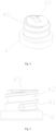
FIG. 4 is a schematic diagram of the structure of a flow restriction seat of a cosmetic packaging bottle restricting backflow in the invention; and -
FIG. 5 is a schematic diagram of the side view structure of the flow restriction seat of a cosmetic packaging bottle restricting backflow in the invention. - The invention is now described in further details in conjunction with the accompanying drawings. These drawings are simplified schematic diagrams that illustrate the basic structure of the invention in a schematic manner only, and therefore show only the components related to the invention.
- As shown in
FIGS. 1 and2 , the cosmetic packaging bottle restricting backflow consists of a soft tube packaging bottle 1 and aliquid discharge head 2, and a non-return valve sheet 6 is installed in theliquid discharge head 2. The non-return valve sheet 6 has a one-way flow restriction function, so that the contents of the soft tube packaging bottle 1 are squeezed out in one direction and cannot flow back, preventing the contents from flowing back and causing contamination of the contents of the soft tube packaging bottle 1. - Refer to
FIG. 2 . A middle part of the non-return valve sheet 6 is provided with across-shaped cutout 61, the non-return valve sheet 6 is closed in the normal state, the non-return valve sheet 6 is squeezed by the contents to open upward and discharge the contents. The flow restriction seat 4 is placed on the mouth of the soft tube packaging bottle 1, and the non-return valve sheet 6 is attached to the upper part of the flow restriction seat 4, the flow restriction seat 4 is provided with a flow restriction channel, and the non-return valve sheet 6 covers the outlet of the flow restriction channel; the bottom of theliquid discharge head 2 has a concave cavity, and the concave cavity part of theliquid discharge head 2 is placed on the flow restriction seat 4, and the inner wall surface of the concave cavity of theliquid discharge head 2 is close to the outer side wall of the flow restriction seat 4. The top surface of the concave cavity of theliquid discharge head 2 is pressed against the circumference of the non-return valve sheet 6, and aliquid discharge cavity 21 is provided in a middle part of theliquid discharge head 2, and thecross-shaped cutout 61 of the non-return valve sheet 6 can be opened in the direction of theliquid discharge cavity 21. Among them, the outer diameter of theliquid discharge cavity 21 is larger than the flow restriction channel, and thecross-shaped cutout 61 of the non-return valve sheet 6 cannot be opened in the direction of the flow restriction channel, which has a one-way flow restriction effect. - In this embodiment, at least one section of the flow restriction channel of the flow restriction seat 4 is a non-linear channel. The process of the contents passing through the flow restriction channel needs to pass through a number of bends, which can slow down the speed of its outflow.
- Specifically, by referring to
FIGS. 4 and 5 , the bottom of the flow restriction seat 4 is a concave cavity structure, and the flow restriction channel includes a through-port 41 placed in the side wall of the flow restriction seat 4, aside groove channel 42 placed between the outer side wall of the flow restriction seat 4 and the liquid discharge head, and anupper groove channel 43 placed in the upper surface of the flow restriction seat 4; the through-port 41, theside groove channel 42, and theupper groove channel 43 are connected to each other in turn. - In this embodiment, the
side groove channel 42 is a spiral structure. Theside groove channel 42 is a groove structure placed on the side wall of the flow restriction seat 4, which is combined with the inner wall surface of the concave cavity of theliquid discharge head 2 to form a complete threaded pipe type channel. - The
upper groove channel 43 extends from the middle to the edge and is connected to theside groove channel 42. The width of theupper groove channel 43, in a groove structure, is much smaller than the outer diameter of theliquid discharge cavity 21. The width of theupper groove channel 43 is not wide enough to allow thecross-shaped cutout 61 of the non-return valve sheet 6 to open downward, and when the non-return valve sheet 6 is under suction, thecross-shaped cutout 61 presses downward against the upper surface of the flow restriction seat 4 in a closed state. - The non-return valve sheet 6 is made of silicone with a hardness of 70 degrees and good flexibility, and the
cross-shaped cutout 61 opens and closes reliably. - The upper part of the
liquid discharge head 2 is theliquid discharge column 5, and the inner cavity of theliquid discharge column 5 forms the aforementionedliquid discharge cavity 21, and theliquid discharge cavity 21 is connected to the outside of theliquid discharge column 5. - The mouth of the soft tube packaging bottle 1 is provided with a threaded holder 11, the bottom surface of the threaded holder 11 is provided with a
limit platform 12, and a middle part of thelimit platform 12 is provided with an opening 121 corresponding to the open concave cavity structure of the bottom surface of the flow restriction seat 4, and the opening 121 is connected to the flow restriction seat 4 and the soft tube packaging bottle. - Refer to
FIG.3 . The flow restriction seat 4 and theliquid discharge head 2 are placed inside the threaded holder 11, and theliquid discharge head 2 is placed on the flow restriction seat 4 and then fitted into the threaded holder 11, and the outer wall of theliquid discharge head 2 is tightly pressed against the inner wall of the threaded holder 11. In order to further stabilize the combination between the outer wall of theliquid discharge head 2 and the threaded holder 11, aconvex ring 22 and aslot 12 are provided between the outer wall of theliquid discharge head 2 and the inner wall of the threaded holder 11. After theliquid discharge head 2 is installed in the threaded holder 11, theslot 12 and theconvex ring 22 are correspondingly clamped to each other for a more stable installation, and theslot 12 and theconvex ring 22 have an arc-shaped structure for easy installation. - Refer to
FIG. 1 . There is anouter cover 3 attached to the outside of theliquid discharge head 2, and theouter cover 3 is screwed to the threaded holder 11. A middle part of theouter cover 3 is provided with a raised plunger 31, and after theouter cover 3 is installed, the plunger 31 closes the outlet port at the upper end of the liquid discharge column 51. - In the detailed description of embodiments, before the non-return valve sheet 6 is used, the
cross-shaped cutout 61 is in the bonding state, gas on both sides is sealed. In the first usage, the pressure in the content squeezing process flushes out thecross-shaped cutout 61, ending its bonding state. - When the contents are filled, the contents are filled from the bottom of the soft tube packaging bottle 1. The time required for the contents to enter the through-
hole 41, theside groove channel 42, and then theupper groove channel 43 is greater than the time required for the entire cosmetic can to be completed, so the non-return valve sheet not 6 is opened, and its closed state can maximize the effective isolation of the air on the other side of the non-return valve sheet 6 to avoid direct contact between the cosmetic contents and the air and prevent microbial or bacterial contamination. It prevents microbial or bacterial contamination and effectively protects the quality of cosmetics. - Specifically, the
groove channel 42 is a semi-circular groove, and the diameter of thegroove channel 42 and the through-hole 41 is between 1.3 and 1.34 mm, forming a flow channel with a narrow diameter and a certain resistance. The threaded pipe-type channel formed between thegroove channel 42 and theliquid discharge head 2 has more than two coils, with a total length of 50.4 mm. The length of theupper groove channel 43 is 5.09 mm, the length of the through-hole 41 is 2.07 mm, i.e., the total length of the flow restriction channel is 57.56 mm, the length of the threaded pipe channel is similar to the length of the soft tube packaging bottle 1, the contents are filled from the bottom of the soft tube packaging bottle 1, filling the whole soft tube packaging bottle 1 first, and then flowing into the threaded pipe channel. In the filling process, the time for the contents to enter the flow restriction channel and reach the non-return valve sheet 6 is much longer than the time to fill the whole soft tube packaging bottle 1, with enough time to adjust or stop filling, so the non-return valve sheet 6 is not open in the filling process, isolating the air on the other side, avoiding direct contact between the cosmetic contents and air, preventing microbial or bacterial contamination and effectively protecting the quality of cosmetics. - The
side groove channel 42 is placed between the outer side wall of the flow restriction seat 4 and the liquid discharge head, and theupper groove channel 43 is placed on the upper surface of the flow restriction seat 4; the through-port 41, theside groove channel 42, and theupper groove channel 43 are connected to each other in turn. - A cosmetic packaging bottle restricting backflow described in the invention has a one-way flow restriction function, so that the contents of the soft tube packaging bottle 1 are extruded in one direction and cannot flow back, preventing the contents from flowing back and causing contamination of the contents of the soft tube packaging bottle 1. The non-return valve sheet 6 has a one-way valve role, the middle is provided with a
cross-shaped cutout 61. The non-return valve sheet 6 is normally closed. When the contents are squeezed out, the non-return valve sheet 6 squeezed by the contents will open upward, the contents are discharged. After the stopping of squeezing, the soft tube packaging bottle 1 has a tendency to reset and will suck back the contents, the contents tend to flow back. At this time, the non-return valve sheet 6 is sucked downward against the upper surface of the flow restriction seat 4 to keep it closed and prevent the contents from flowing back. With a spiral flow restriction channel, the contents enter from the side and exit from the top, which can limit the outflow rate of the contents, to squeeze accurately and prevent the contents from splashing and spilling due to excessive force during squeezing, to avoid waste. - With the aforementioned ideal embodiment of the invention as the inspiration, the relevant staff can make various changes and modifications without deviating from the scope of the technical idea of the invention. The technical scope of the invention is not limited to the contents of the specification, but must be determined according to the scope of the claims.
Claims (10)
- A cosmetic packaging bottle restricting backflow, including a soft tube packaging bottle and a liquid discharge head, wherein: and also including a non-return valve sheet, which is placed within the liquid discharge head, the non-return valve sheet has a one-way flow restriction function, so that contents of the soft tube packaging bottle are squeezed out in one direction and cannot flow back.
- The cosmetic packaging bottle restricting backflow according to claim 1, wherein: a middle part of the non-return valve sheet is provided with a cross-shaped cutout, the non-return valve sheet is closed in the normal state, the non-return valve sheet is squeezed by the contents to open upward to discharge contents.
- The cosmetic packaging bottle restricting backflow according to claim 2, wherein: the mouth of the soft tube packaging bottle is provided with a flow restriction seat, the non-return valve sheet is attached to an upper part of the flow restriction seat, and the flow restriction seat is provided with a flow restriction channel; the liquid discharge head has a concave cavity at the bottom, the liquid discharge head is capped on the flow restriction seat, pressed against the circumference of the non-return valve sheet, a middle part of the liquid discharge head is provided with a liquid discharge cavity, and the cross-shaped cutout of the non-return valve sheet can be opened in the direction of the liquid discharge cavity.
- The cosmetic packaging bottle restricting backflow according to claim 3, wherein: the bottom of the flow restriction seat is a concave cavity structure, the flow restriction channel includes a through-port placed at the side wall of the flow restriction seat, a side groove channel placed between an outer side wall of the flow restriction seat and the liquid discharge head, and an upper groove channel placed in an upper surface of the flow restriction seat; the through-port, side groove channel, and upper groove channel are connected to each other in turn.
- The cosmetic packaging bottle restricting backflow according to claim 4, wherein: the side groove channel is a spiral structure.
- The cosmetic packaging bottle restricting backflow according to claim 5, wherein: the upper groove channel extends from the middle to the edge and is connected to the side groove channel.
- The cosmetic packaging bottle restricting backflow according to claim 6, wherein: the upper part of the liquid discharge head is a liquid discharge column, the inner cavity of the liquid discharge column forms the liquid discharge cavity, and the liquid discharge cavity is connected to the outside of the liquid discharge column.
- The cosmetic packaging bottle restricting backflow according to claim 7, wherein: the mouth of the soft tube packaging bottle is provided with a threaded holder, the bottom surface of the threaded holder is provided with a limit platform, a middle part of the limit platform is provided with an opening corresponding to the open concave cavity structure of the bottom surface of the flow restriction seat, the flow restriction seat and the liquid discharge head are placed inside the threaded holder, and the outer wall of the liquid discharge head is close to the inner wall of the threaded holder.
- The cosmetic packaging bottle restricting backflow according to claim 8, wherein: an outer wall of the liquid discharge head and the inner wall of the threaded holder are provided with a slot and a convex ring, respectively, and the slot and the convex ring correspond to each other.
- The cosmetic packaging bottle restricting backflow according to claim 9, wherein: and also includes an outer cover, the outer cover is screwed onto the threaded holder, and a raised plunger is placed in a middle part of the outer cover, and the plunger closes the upper end of the liquid discharge cavity after the outer cover is installed.
Applications Claiming Priority (1)
| Application Number | Priority Date | Filing Date | Title |
|---|---|---|---|
| CN202223284958 | 2022-12-06 |
Publications (3)
| Publication Number | Publication Date |
|---|---|
| EP4381991A1 true EP4381991A1 (en) | 2024-06-12 |
| EP4381991B1 EP4381991B1 (en) | 2025-01-29 |
| EP4381991C0 EP4381991C0 (en) | 2025-01-29 |
Family
ID=84785151
Family Applications (1)
| Application Number | Title | Priority Date | Filing Date |
|---|---|---|---|
| EP23150003.4A Active EP4381991B1 (en) | 2022-12-06 | 2023-01-02 | A cosmetic packaging bottle restricting backflow |
Country Status (4)
| Country | Link |
|---|---|
| US (1) | US20240180315A1 (en) |
| EP (1) | EP4381991B1 (en) |
| ES (1) | ES3023853T3 (en) |
| HU (1) | HUE070587T2 (en) |
Citations (2)
| Publication number | Priority date | Publication date | Assignee | Title |
|---|---|---|---|---|
| WO2016186748A1 (en) * | 2015-05-18 | 2016-11-24 | Aptargroup, Inc. | Dispensing closure |
| CN212830185U (en) * | 2019-09-26 | 2021-03-30 | 石家庄香悦文化传播有限公司 | Bottle is tried to emulsion for cosmetics |
Family Cites Families (6)
| Publication number | Priority date | Publication date | Assignee | Title |
|---|---|---|---|---|
| US5305786A (en) * | 1993-01-14 | 1994-04-26 | Reseal International Limited Partnership | One-way valve assembly |
| US5950878A (en) * | 1997-08-04 | 1999-09-14 | Steris Corporation | Dispensing tube valve assembly |
| US6095382A (en) * | 1998-09-21 | 2000-08-01 | Aptargroup, Inc. | Container and closure with dispensing valve and separate releasable internal shipping seal |
| US8281810B2 (en) * | 2008-04-30 | 2012-10-09 | The Viking Corporation | Dry valve for sprinkler system |
| US11219298B2 (en) * | 2017-11-10 | 2022-01-11 | Aqua Fix USA, Inc. | Squeezable hybrid water bottle with integrated filter |
| TW202005623A (en) * | 2018-04-06 | 2020-02-01 | 美商蒂克利爾公司 | Systems and methods for delivery of a therapeutic agent |
-
2023
- 2023-01-02 EP EP23150003.4A patent/EP4381991B1/en active Active
- 2023-01-02 HU HUE23150003A patent/HUE070587T2/en unknown
- 2023-01-02 ES ES23150003T patent/ES3023853T3/en active Active
- 2023-01-11 US US18/095,928 patent/US20240180315A1/en active Pending
Patent Citations (2)
| Publication number | Priority date | Publication date | Assignee | Title |
|---|---|---|---|---|
| WO2016186748A1 (en) * | 2015-05-18 | 2016-11-24 | Aptargroup, Inc. | Dispensing closure |
| CN212830185U (en) * | 2019-09-26 | 2021-03-30 | 石家庄香悦文化传播有限公司 | Bottle is tried to emulsion for cosmetics |
Also Published As
| Publication number | Publication date |
|---|---|
| US20240180315A1 (en) | 2024-06-06 |
| EP4381991B1 (en) | 2025-01-29 |
| ES3023853T3 (en) | 2025-06-03 |
| HUE070587T2 (en) | 2025-06-28 |
| EP4381991C0 (en) | 2025-01-29 |
Similar Documents
| Publication | Publication Date | Title |
|---|---|---|
| US5836484A (en) | Contamination-safe multiple-dose dispensing cartridge for flowable materials | |
| US4828150A (en) | Device for discharging cream or paste-like material from a container | |
| US20020014499A1 (en) | Apparatus and method for dispensing a product | |
| EP0923898A1 (en) | Non-spilling beverage lid | |
| CN110269368B (en) | Drain container | |
| DE10109064A1 (en) | Opening system with back ventilation mechanism | |
| US9386870B2 (en) | Check valve drinking device | |
| CN100386247C (en) | Container and valve assembly for storing and dispensing substances, and related methods | |
| EP4381991A1 (en) | A cosmetic packaging bottle restricting backflow | |
| CN113002974B (en) | Emulsion double material discharge container | |
| JPH10120054A (en) | Ejection container | |
| KR20200105804A (en) | Cosmetic container | |
| US4279363A (en) | Non-inverting fluid dispenser | |
| US20100096407A1 (en) | Container and valve assembly for storing and dispensing substances, and related method | |
| CN112607214A (en) | Dripper structure capable of controlling dripping amount and dripping speed and dripping bottle | |
| CN215460210U (en) | Leakage-proof liquid weight bottle | |
| CN218869646U (en) | A flow-limiting cosmetic bottle | |
| CN210000855U (en) | Sanitary bottle cap structure with more liquid discharging and no liquid leakage when pouring | |
| CN114873071A (en) | A foam pump with suction effect | |
| CN216402399U (en) | Bacteria filter and fresh-keeping bottle cap | |
| JP2004210351A (en) | Liquid spout container | |
| JP2003221052A (en) | Liquid container | |
| CN217779458U (en) | Container with one-way valve | |
| CN111907911A (en) | Portable bottle | |
| CN213058276U (en) | Stepless control device for pressing stroke of container |
Legal Events
| Date | Code | Title | Description |
|---|---|---|---|
| PUAI | Public reference made under article 153(3) epc to a published international application that has entered the european phase |
Free format text: ORIGINAL CODE: 0009012 |
|
| STAA | Information on the status of an ep patent application or granted ep patent |
Free format text: STATUS: REQUEST FOR EXAMINATION WAS MADE |
|
| 17P | Request for examination filed |
Effective date: 20240326 |
|
| AK | Designated contracting states |
Kind code of ref document: A1 Designated state(s): AL AT BE BG CH CY CZ DE DK EE ES FI FR GB GR HR HU IE IS IT LI LT LU LV MC ME MK MT NL NO PL PT RO RS SE SI SK SM TR |
|
| P01 | Opt-out of the competence of the unified patent court (upc) registered |
Free format text: CASE NUMBER: APP_38013/2024 Effective date: 20240626 |
|
| GRAP | Despatch of communication of intention to grant a patent |
Free format text: ORIGINAL CODE: EPIDOSNIGR1 |
|
| STAA | Information on the status of an ep patent application or granted ep patent |
Free format text: STATUS: GRANT OF PATENT IS INTENDED |
|
| INTG | Intention to grant announced |
Effective date: 20240924 |
|
| GRAS | Grant fee paid |
Free format text: ORIGINAL CODE: EPIDOSNIGR3 |
|
| GRAA | (expected) grant |
Free format text: ORIGINAL CODE: 0009210 |
|
| STAA | Information on the status of an ep patent application or granted ep patent |
Free format text: STATUS: THE PATENT HAS BEEN GRANTED |
|
| AK | Designated contracting states |
Kind code of ref document: B1 Designated state(s): AL AT BE BG CH CY CZ DE DK EE ES FI FR GB GR HR HU IE IS IT LI LT LU LV MC ME MK MT NL NO PL PT RO RS SE SI SK SM TR |
|
| REG | Reference to a national code |
Ref country code: GB Ref legal event code: FG4D |
|
| REG | Reference to a national code |
Ref country code: CH Ref legal event code: EP |
|
| REG | Reference to a national code |
Ref country code: DE Ref legal event code: R096 Ref document number: 602023001796 Country of ref document: DE |
|
| REG | Reference to a national code |
Ref country code: IE Ref legal event code: FG4D |
|
| P04 | Withdrawal of opt-out of the competence of the unified patent court (upc) registered |
Free format text: CASE NUMBER: APP_9354/2025 Effective date: 20250225 |
|
| U01 | Request for unitary effect filed |
Effective date: 20250129 |
|
| U02 | Date of filing of request for unitary effect changed |
Effective date: 20250226 |
|
| U07 | Unitary effect registered |
Designated state(s): AT BE BG DE DK EE FI FR IT LT LU LV MT NL PT RO SE SI Effective date: 20250307 |
|
| REG | Reference to a national code |
Ref country code: ES Ref legal event code: FG2A Ref document number: 3023853 Country of ref document: ES Kind code of ref document: T3 Effective date: 20250603 |
|
| REG | Reference to a national code |
Ref country code: HU Ref legal event code: AG4A Ref document number: E070587 Country of ref document: HU |
|
| PG25 | Lapsed in a contracting state [announced via postgrant information from national office to epo] |
Ref country code: RS Free format text: LAPSE BECAUSE OF FAILURE TO SUBMIT A TRANSLATION OF THE DESCRIPTION OR TO PAY THE FEE WITHIN THE PRESCRIBED TIME-LIMIT Effective date: 20250429 |
|
| PG25 | Lapsed in a contracting state [announced via postgrant information from national office to epo] |
Ref country code: PL Free format text: LAPSE BECAUSE OF FAILURE TO SUBMIT A TRANSLATION OF THE DESCRIPTION OR TO PAY THE FEE WITHIN THE PRESCRIBED TIME-LIMIT Effective date: 20250129 |
|
| PG25 | Lapsed in a contracting state [announced via postgrant information from national office to epo] |
Ref country code: NO Free format text: LAPSE BECAUSE OF FAILURE TO SUBMIT A TRANSLATION OF THE DESCRIPTION OR TO PAY THE FEE WITHIN THE PRESCRIBED TIME-LIMIT Effective date: 20250429 Ref country code: IS Free format text: LAPSE BECAUSE OF FAILURE TO SUBMIT A TRANSLATION OF THE DESCRIPTION OR TO PAY THE FEE WITHIN THE PRESCRIBED TIME-LIMIT Effective date: 20250529 |
|
| PG25 | Lapsed in a contracting state [announced via postgrant information from national office to epo] |
Ref country code: HR Free format text: LAPSE BECAUSE OF FAILURE TO SUBMIT A TRANSLATION OF THE DESCRIPTION OR TO PAY THE FEE WITHIN THE PRESCRIBED TIME-LIMIT Effective date: 20250129 |
|
| PG25 | Lapsed in a contracting state [announced via postgrant information from national office to epo] |
Ref country code: GR Free format text: LAPSE BECAUSE OF FAILURE TO SUBMIT A TRANSLATION OF THE DESCRIPTION OR TO PAY THE FEE WITHIN THE PRESCRIBED TIME-LIMIT Effective date: 20250430 |
|
| PG25 | Lapsed in a contracting state [announced via postgrant information from national office to epo] |
Ref country code: SM Free format text: LAPSE BECAUSE OF FAILURE TO SUBMIT A TRANSLATION OF THE DESCRIPTION OR TO PAY THE FEE WITHIN THE PRESCRIBED TIME-LIMIT Effective date: 20250129 |
|
| PG25 | Lapsed in a contracting state [announced via postgrant information from national office to epo] |
Ref country code: CZ Free format text: LAPSE BECAUSE OF FAILURE TO SUBMIT A TRANSLATION OF THE DESCRIPTION OR TO PAY THE FEE WITHIN THE PRESCRIBED TIME-LIMIT Effective date: 20250129 |
|
| PG25 | Lapsed in a contracting state [announced via postgrant information from national office to epo] |
Ref country code: SK Free format text: LAPSE BECAUSE OF FAILURE TO SUBMIT A TRANSLATION OF THE DESCRIPTION OR TO PAY THE FEE WITHIN THE PRESCRIBED TIME-LIMIT Effective date: 20250129 |
|
| PLBE | No opposition filed within time limit |
Free format text: ORIGINAL CODE: 0009261 |
|
| STAA | Information on the status of an ep patent application or granted ep patent |
Free format text: STATUS: NO OPPOSITION FILED WITHIN TIME LIMIT |
|
| REG | Reference to a national code |
Ref country code: CH Ref legal event code: L10 Free format text: ST27 STATUS EVENT CODE: U-0-0-L10-L00 (AS PROVIDED BY THE NATIONAL OFFICE) Effective date: 20251210 |
|
| U20 | Renewal fee for the european patent with unitary effect paid |
Year of fee payment: 4 Effective date: 20251105 |
|
| 26N | No opposition filed |
Effective date: 20251030 |
|
| REG | Reference to a national code |
Ref country code: CH Ref legal event code: U11 Free format text: ST27 STATUS EVENT CODE: U-0-0-U10-U11 (AS PROVIDED BY THE NATIONAL OFFICE) Effective date: 20260201 |
|
| PGFP | Annual fee paid to national office [announced via postgrant information from national office to epo] |
Ref country code: TR Payment date: 20260101 Year of fee payment: 4 |
|
| PGFP | Annual fee paid to national office [announced via postgrant information from national office to epo] |
Ref country code: CH Payment date: 20260201 Year of fee payment: 4 |