EP4381931A1 - Agricultural disc mower with fully reversible knife - Google Patents
Agricultural disc mower with fully reversible knife Download PDFInfo
- Publication number
- EP4381931A1 EP4381931A1 EP23214372.7A EP23214372A EP4381931A1 EP 4381931 A1 EP4381931 A1 EP 4381931A1 EP 23214372 A EP23214372 A EP 23214372A EP 4381931 A1 EP4381931 A1 EP 4381931A1
- Authority
- EP
- European Patent Office
- Prior art keywords
- knife
- edges
- mounting feature
- cutting
- disc
- Prior art date
- Legal status (The legal status is an assumption and is not a legal conclusion. Google has not performed a legal analysis and makes no representation as to the accuracy of the status listed.)
- Granted
Links
Images





Classifications
-
- A—HUMAN NECESSITIES
- A01—AGRICULTURE; FORESTRY; ANIMAL HUSBANDRY; HUNTING; TRAPPING; FISHING
- A01D—HARVESTING; MOWING
- A01D34/00—Mowers; Mowing apparatus of harvesters
- A01D34/01—Mowers; Mowing apparatus of harvesters characterised by features relating to the type of cutting apparatus
- A01D34/412—Mowers; Mowing apparatus of harvesters characterised by features relating to the type of cutting apparatus having rotating cutters
- A01D34/63—Mowers; Mowing apparatus of harvesters characterised by features relating to the type of cutting apparatus having rotating cutters having cutters rotating about a vertical axis
- A01D34/73—Cutting apparatus
- A01D34/733—Cutting-blade mounting means
-
- A—HUMAN NECESSITIES
- A01—AGRICULTURE; FORESTRY; ANIMAL HUSBANDRY; HUNTING; TRAPPING; FISHING
- A01D—HARVESTING; MOWING
- A01D34/00—Mowers; Mowing apparatus of harvesters
- A01D34/01—Mowers; Mowing apparatus of harvesters characterised by features relating to the type of cutting apparatus
- A01D34/412—Mowers; Mowing apparatus of harvesters characterised by features relating to the type of cutting apparatus having rotating cutters
- A01D34/63—Mowers; Mowing apparatus of harvesters characterised by features relating to the type of cutting apparatus having rotating cutters having cutters rotating about a vertical axis
-
- A—HUMAN NECESSITIES
- A01—AGRICULTURE; FORESTRY; ANIMAL HUSBANDRY; HUNTING; TRAPPING; FISHING
- A01D—HARVESTING; MOWING
- A01D34/00—Mowers; Mowing apparatus of harvesters
- A01D34/01—Mowers; Mowing apparatus of harvesters characterised by features relating to the type of cutting apparatus
- A01D34/412—Mowers; Mowing apparatus of harvesters characterised by features relating to the type of cutting apparatus having rotating cutters
- A01D34/63—Mowers; Mowing apparatus of harvesters characterised by features relating to the type of cutting apparatus having rotating cutters having cutters rotating about a vertical axis
- A01D34/64—Mowers; Mowing apparatus of harvesters characterised by features relating to the type of cutting apparatus having rotating cutters having cutters rotating about a vertical axis mounted on a vehicle, e.g. a tractor, or drawn by an animal or a vehicle
- A01D34/66—Mowers; Mowing apparatus of harvesters characterised by features relating to the type of cutting apparatus having rotating cutters having cutters rotating about a vertical axis mounted on a vehicle, e.g. a tractor, or drawn by an animal or a vehicle with two or more cutters
-
- A—HUMAN NECESSITIES
- A01—AGRICULTURE; FORESTRY; ANIMAL HUSBANDRY; HUNTING; TRAPPING; FISHING
- A01D—HARVESTING; MOWING
- A01D34/00—Mowers; Mowing apparatus of harvesters
- A01D34/01—Mowers; Mowing apparatus of harvesters characterised by features relating to the type of cutting apparatus
- A01D34/412—Mowers; Mowing apparatus of harvesters characterised by features relating to the type of cutting apparatus having rotating cutters
- A01D34/63—Mowers; Mowing apparatus of harvesters characterised by features relating to the type of cutting apparatus having rotating cutters having cutters rotating about a vertical axis
- A01D34/64—Mowers; Mowing apparatus of harvesters characterised by features relating to the type of cutting apparatus having rotating cutters having cutters rotating about a vertical axis mounted on a vehicle, e.g. a tractor, or drawn by an animal or a vehicle
- A01D34/66—Mowers; Mowing apparatus of harvesters characterised by features relating to the type of cutting apparatus having rotating cutters having cutters rotating about a vertical axis mounted on a vehicle, e.g. a tractor, or drawn by an animal or a vehicle with two or more cutters
- A01D34/664—Disc cutter bars
-
- A—HUMAN NECESSITIES
- A01—AGRICULTURE; FORESTRY; ANIMAL HUSBANDRY; HUNTING; TRAPPING; FISHING
- A01D—HARVESTING; MOWING
- A01D34/00—Mowers; Mowing apparatus of harvesters
- A01D34/01—Mowers; Mowing apparatus of harvesters characterised by features relating to the type of cutting apparatus
- A01D34/412—Mowers; Mowing apparatus of harvesters characterised by features relating to the type of cutting apparatus having rotating cutters
- A01D34/63—Mowers; Mowing apparatus of harvesters characterised by features relating to the type of cutting apparatus having rotating cutters having cutters rotating about a vertical axis
- A01D34/73—Cutting apparatus
- A01D34/736—Flail type
Definitions
- a typical mower generally includes a frame, a hitch coupled to the vehicle, and a cutter bar such as a sickle bar or rotary disc cutter bar for severing the crop from the field.
- the mower may further include other elements such as a reel to assist crop feeding, an auger or belts to convey crop to a central discharge point, and a flail or set of rollers for conditioning crop as it is ejected rearwardly out of the mower.
- a disc cutter bar generally includes multiple juxtaposed cutterheads for cutting the standing crop. Each cutterhead may consist of a rotating disc with cutting blades or knives affixed to the body of the disc.
- the knives of a cutter bar are known wear items that are intended to be replaced or repaired with some frequency. While it is known that knives need to be replaced or repaired, it is inconvenient to replace or repair the knives. Many users do not want to carry replacement knives or repair tools with the mower, which requires the mower to be brought to a service area for knife replacement or repair and increases downtime of the mower. The alternative is to operate the machine with a dull or broken knife edge, which can result in poor cut quality.
- a cutter bar for an agricultural implement includes a frame and a plurality of disc cutters carried by the frame. At least one of the disc cutters includes: a disc body configured to rotate in a rotation direction; a knife mount carried by the disc body and including a body mounting feature; and a knife coupled to the knife mount.
- an agricultural mowing assembly includes an agricultural vehicle and an agricultural implement coupled to the agricultural vehicle.
- the agricultural implement has a cutter bar that includes a frame and a plurality of disc cutters carried by the frame. At least one of the disc cutters includes: a disc body configured to rotate in a rotation direction; a knife mount carried by the disc body and including a body mounting feature; and a knife coupled to the knife mount.
- the agricultural vehicle 110 generally includes a chassis 111, a prime mover, wheels and/or tracks 112, and a cab 113 for housing the operator.
- the chassis 111 may at least partially carry the front and rear mowing devices 120, 130.
- the vehicle 110 can be in the form of a tractor, self-propelled windrower, or any other desired agricultural vehicle.
- the front and rear mowing devices 120, 130 are connected to the chassis 111 of the agricultural vehicle 110.
- the front mowing device 120 for example, may be centrally mounted onto the driving vehicle 110 such that the agricultural vehicle 110 carries the front mowing device 120.
- the rear mowing device 130 may be coupled to a tongue coupler on the chassis 111 by a pivotable tongue that can change the angular position of the rear mowing device 130 relative to the forward direction of travel.
- the mowing devices 120, 130 are in the form of mower conditioners; however, the mowing devices 120, 130 can be in the form of any desired mowing devices such as mowers, windrowers, cutter bars, or windrow inverters.
- Each mowing device 120, 130 may include a frame 121, 131, a reel 122, 132 with tines rotatably connected to the frame 121, 131, a cutter bar 133, a conditioner 134, e.g. at least one flail conditioner or at least two conditioning rollers 134, and/or a crop gate 135, e.g. swath gate and/or windrow forming shields, for directing the crop material out of the mowing device 120, 130 and onto the field in a windrow or swath (as shown in FIG. 2 with respect to the rear mowing device 130).
- the illustrated cutter bar 133 is in the form of a rotary disc cutter bar 133 with multiple disc cutters 136 carried by a frame of the cutter bar 133.
- the knife 330 may, for example, be formed of a metal or other high-strength material that can be ground or otherwise sharpened to produce the cutting edges 413, 414, 423, 424.
- An exemplary material includes, but is not limited to, hardened steel.
- one or more of the edges 413, 414, 423, 424 is coated with a high toughness material to further toughen the edges 413, 414, 423, 424 for cutting.
- Exemplary high toughness materials include, but are not limited to, carbides such as tungsten carbide. It should therefore be appreciated that the knife 330 can be formed from a variety of different materials.
- the knife 330 is illustrated in a first orientation in FIG. 4 and a second orientation in FIG. 5 .
- the first edge 413 and the second edge 423 are on a leading side 331 of the knife 330 and the other first edge 414 and the other second edge 424 are on a trailing side 332 of the knife 330.
- the leading side 331 and the trailing side 332 are described with respect to the rotation direction R that the knife 330 will rotate during operation.
- the first edge 413 on the leading side 331 of the knife 330 will be the cutting edge that tends to cut crop material while the other edges 414, 423, 424 will generally not cut crop material during rotation in the rotation direction R.
- first edges 413, 414 extend in parallel so the first cutting angle ⁇ 1 of the first edges 413, 414 is the same and the second edges 423, 424 extend in parallel so the second cutting angle ⁇ 2 of the second edges 423, 424 is the same.
- first cutting angle ⁇ 1 and the second cutting angle ⁇ 2 are the same with respect to their respective knife surface 412, 422.
- the first cutting angle ⁇ 1 and/or the second cutting angle ⁇ 2 may be, for example, between 20° and 40°, such as 30°, relative to the respective knife surface 412, 422. It should be appreciated that the previously described cutting angles ⁇ 1 and ⁇ 2 are exemplary only.
Landscapes
- Life Sciences & Earth Sciences (AREA)
- Environmental Sciences (AREA)
- Harvester Elements (AREA)
Abstract
Description
- The present invention pertains to agricultural implements and, more specifically, to disc cutters for agricultural mowing devices.
- Mowers and mower conditioners are often employed to cut crop material, such as hay or grass, and deposit the cut crop into windrows in a field. For cutting smaller fields, a single pull-type mower or mower conditioner may be attached to the rear of an agricultural driving vehicle. For cutting large fields, the driving vehicle may push a front mounted mower or mower conditioner and optionally tow an additional rear mounted mower or mower conditioner.
- A typical mower generally includes a frame, a hitch coupled to the vehicle, and a cutter bar such as a sickle bar or rotary disc cutter bar for severing the crop from the field. The mower may further include other elements such as a reel to assist crop feeding, an auger or belts to convey crop to a central discharge point, and a flail or set of rollers for conditioning crop as it is ejected rearwardly out of the mower. A disc cutter bar generally includes multiple juxtaposed cutterheads for cutting the standing crop. Each cutterhead may consist of a rotating disc with cutting blades or knives affixed to the body of the disc.
- The knives of a cutter bar are known wear items that are intended to be replaced or repaired with some frequency. While it is known that knives need to be replaced or repaired, it is inconvenient to replace or repair the knives. Many users do not want to carry replacement knives or repair tools with the mower, which requires the mower to be brought to a service area for knife replacement or repair and increases downtime of the mower. The alternative is to operate the machine with a dull or broken knife edge, which can result in poor cut quality.
- What is needed in the art is a way to reduce down time associated with replacing knives on an agricultural machine.
- Exemplary embodiments disclosed herein provide disc cutters with a knife that is structured so four edges of the knife can be used as cutting edges, allowing the knife to be flipped and rotated before replacing the knife.
- In some exemplary embodiments provided according to the present disclosure a disc cutter for an agricultural implement includes: a disc body configured to rotate in a rotation direction; a knife mount carried by the disc body and including a body mounting feature; and a knife coupled to the knife mount. The knife includes: a first cutting section having a first knife mounting feature disposed on or in a first knife surface between a pair of first edges of the first cutting section and configured to couple with the body mounting feature, each of the first edges defining a first cutting angle with respect to the first knife surface such that the first edges extend in parallel; and a second cutting section having a second knife mounting feature disposed on or in a second knife surface between a pair of second edges of the second cutting section and configured to couple with the body mounting feature, each of the second edges defining a second cutting angle with respect to the second knife surface such that the second edges extend in parallel.
- In some exemplary embodiments provided according to the present disclosure, a cutter bar for an agricultural implement includes a frame and a plurality of disc cutters carried by the frame. At least one of the disc cutters includes: a disc body configured to rotate in a rotation direction; a knife mount carried by the disc body and including a body mounting feature; and a knife coupled to the knife mount. The knife includes: a first cutting section having a first knife mounting feature disposed on or in a first knife surface between a pair of first edges of the first cutting section and configured to couple with the body mounting feature, each of the first edges defining a first cutting angle with respect to the first knife surface such that the first edges extend in parallel; and a second cutting section having a second knife mounting feature disposed on or in a second knife surface between a pair of second edges of the second cutting section and configured to couple with the body mounting feature, each of the second edges defining a second cutting angle with respect to the second knife surface such that the second edges extend in parallel.
- In some exemplary embodiments provided according to the present disclosure, an agricultural mowing assembly includes an agricultural vehicle and an agricultural implement coupled to the agricultural vehicle. The agricultural implement has a cutter bar that includes a frame and a plurality of disc cutters carried by the frame. At least one of the disc cutters includes: a disc body configured to rotate in a rotation direction; a knife mount carried by the disc body and including a body mounting feature; and a knife coupled to the knife mount. The knife includes: a first cutting section having a first knife mounting feature disposed on or in a first knife surface between a pair of first edges of the first cutting section and configured to couple with the body mounting feature, each of the first edges defining a first cutting angle with respect to the first knife surface such that the first edges extend in parallel; and a second cutting section having a second knife mounting feature disposed on or in a second knife surface between a pair of second edges of the second cutting section and configured to couple with the body mounting feature, each of the second edges defining a second cutting angle with respect to the second knife surface such that the second edges extend in parallel.
- An advantage that may be realized by exemplary embodiments provided according to the present disclosure is that the knife having four cutting edges allows the knife to be flipped or rotated, rather than replaced, to provide a sharp cutting edge.
- For the purpose of illustration, there are shown in the drawings certain embodiments of the present invention. It should be understood, however, that the invention is not limited to the precise arrangements, dimensions, and instruments shown. Like numerals indicate like elements throughout the drawings. In the drawings:
-
FIG. 1 illustrates a perspective view of an exemplary embodiment of an agricultural mowing assembly including an agricultural vehicle and an agricultural implement provided according to the present disclosure; -
FIG. 2 illustrates a side sectional view of the agricultural implement ofFIG. 1 ; -
FIG. 3 illustrates a perspective view of an exemplary embodiment of disc cutters provided according to the invention including a knife; -
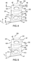
FIG. 4 illustrates a perspective view of one of the knives ofFIG. 3 in a first orientation; -
FIG. 4A illustrates a cross-section of the knife ofFIG. 4 taken alongline 4A-4A; -
FIG. 4B illustrates a cross-section of the knife ofFIG. 4 taken alongline 4B-4B; -
FIG. 5 illustrates a perspective view of the knife ofFIG. 4 after flipping the knife to a second orientation from the first orientation illustrated inFIG. 4 ; -
FIG. 6 illustrates a perspective view of the knife ofFIGS. 4-5 after rotating the knife to a third orientation from the second orientation illustrated inFIG. 5 ; -
FIG. 7 illustrates a perspective view of the knife ofFIGS. 4-6 after flipping the knife to a fourth orientation from the third orientation illustrated inFIG. 6 ; and -
FIG. 8 is a flow chart illustrating an embodiment of a method of mounting and adjusting a knife of a cutting disc provided according to the present disclosure. - Referring now to the drawings, and more particularly to
FIGS. 1-2 , there is shown anagricultural mowing assembly 100 which includes anagricultural vehicle 110 and at least one agricultural implement illustrated in the form of twomowing devices agricultural vehicle 110. Theagricultural mowing assembly 100 may include tandem front andrear mowing devices mowers - The
agricultural vehicle 110 generally includes achassis 111, a prime mover, wheels and/ortracks 112, and acab 113 for housing the operator. Thechassis 111 may at least partially carry the front andrear mowing devices vehicle 110 can be in the form of a tractor, self-propelled windrower, or any other desired agricultural vehicle. - The front and
rear mowing devices chassis 111 of theagricultural vehicle 110. Thefront mowing device 120, for example, may be centrally mounted onto thedriving vehicle 110 such that theagricultural vehicle 110 carries thefront mowing device 120. Therear mowing device 130 may be coupled to a tongue coupler on thechassis 111 by a pivotable tongue that can change the angular position of therear mowing device 130 relative to the forward direction of travel. As shown, themowing devices mowing devices mowing device frame reel frame cutter bar 133, aconditioner 134, e.g. at least one flail conditioner or at least twoconditioning rollers 134, and/or acrop gate 135, e.g. swath gate and/or windrow forming shields, for directing the crop material out of themowing device FIG. 2 with respect to the rear mowing device 130). The illustratedcutter bar 133 is in the form of a rotarydisc cutter bar 133 withmultiple disc cutters 136 carried by a frame of thecutter bar 133. - Referring now to
FIG. 3 , two of thedisc cutters 136 are illustrated. Each of thedisc cutters 136 includes adisc body 310 configured to rotate in a rotation direction R, aknife mount 320 carried by thedisc body 310 that includes abody mounting feature 321, and aknife 330 coupled to theknife mount 320. It should be appreciated that while twodisc cutters 136 are illustrated inFIG. 3 , one disc cutter or more than two disc cutters may be included in thecutter bar 133 provided according to the present disclosure. Further, whileFIG. 3 only illustrates oneknife 330 for eachdisc cutter 136, thedisc cutters 136 may carry more than one knife, e.g., two knives, three knives, four knives, etc. - Many known knives have two cutting edges. The knife having two cutting edges allows the knife to be flipped or rotated when one of the cutting edges is dull and/or broken so the sharp cutting edge can be used to cut crop material. While such knives are effective and convenient for a farmer, the knives can only be rotated or flipped once before replacement is required.
- To address some of the issues with known knives, and referring now to
FIGS. 4-7 , theknife 330 provided according to the present disclosure includes afirst cutting section 410 and asecond cutting section 420. It should be appreciated that while only one of theknives 330 is illustrated inFIGS. 4-7 , all of the knives of thecutter bar 133 may be similar. Thefirst cutting section 410 includes a firstknife mounting feature 411 disposed on or in afirst knife surface 412 between a pair offirst edges first cutting section 410. The firstknife mounting feature 411 is configured to couple with thebody mounting feature 321, which mounts theknife 330 to theknife mount 320. Each of thefirst edges first knife surface 412 such that thefirst edges FIG. 4A . Similarly, thesecond cutting section 420 includes a secondknife mounting feature 421 disposed on or in asecond knife surface 422 between a pair ofsecond edges second cutting section 420. The secondknife mounting feature 421 is configured to couple with thebody mounting feature 321, which can also mount theknife 330 to theknife mount 320. In this respect, either of the knife mounting features 411, 421 may be used to mount theknife 330 to theknife mount 320, the significance of which will be described further herein. Each of thesecond edges second knife surface 422 such that thesecond edges FIG. 4B . Theknife 330 may, for example, be formed of a metal or other high-strength material that can be ground or otherwise sharpened to produce the cutting edges 413, 414, 423, 424. An exemplary material includes, but is not limited to, hardened steel. In some embodiments, one or more of theedges edges knife 330 can be formed from a variety of different materials. - Referring specifically now to
FIGS. 4-5 , theknife 330 is illustrated in a first orientation inFIG. 4 and a second orientation inFIG. 5 . In the first orientation, thefirst edge 413 and thesecond edge 423 are on aleading side 331 of theknife 330 and the otherfirst edge 414 and the othersecond edge 424 are on a trailingside 332 of theknife 330. The leadingside 331 and the trailingside 332 are described with respect to the rotation direction R that theknife 330 will rotate during operation. In the first orientation illustrated inFIG. 4 , thefirst edge 413 on the leadingside 331 of theknife 330 will be the cutting edge that tends to cut crop material while theother edges knife 330 is flipped to the second orientation illustrated inFIG. 5 , thefirst edge 414 and thesecond edge 424 are now on the leadingside 331 of the knife and the otherfirst edge 413 and the othersecond edge 423 are on the trailingside 332 of theknife 330 so thefirst edge 414 will be the cutting edge that tends to cut crop material while theother edges - The
knife 330 may be mounted to theknife mount 320 in both the first orientation and the second orientation by coupling the secondknife mounting feature 421 to thebody mounting feature 321. Theknife 330 can be re-oriented by uncoupling the secondknife mounting feature 421 from thebody mounting feature 321 and then flipping theknife 330 before re-coupling the secondknife mounting feature 421 to thebody mounting feature 321. Re-orienting theknife 330 from the first orientation to the second orientation in this manner allows the cutting edge to be changed from thefirst edge 413 in the first orientation to thesecond edge 414 in the second orientation when, for example, thefirst edge 413 has become dull or otherwise damaged and a fresh cutting edge is desired. The first edges 413, 414 extending in parallel to each other ensures that the cutting edge is generally the same regardless of whether theknife 330 is in the first orientation or the second orientation. - Referring now to
FIGS. 6 and 7 as well, theknife 330 is illustrated in a third orientation inFIG. 6 after rotating theknife 330 from the second orientation illustrated inFIG. 5 and in a fourth orientation inFIG. 7 after flipping theknife 330 from the third orientation illustrated inFIG. 6 . As used herein, "rotating" differs from "flipping" in that rotating theknife 330 refers to rotation of theknife 330 about a point within a rotation plane while flipping refers to rotation of theknife 330 about the same point in a manner that moves theknife 330 out of the rotation plane. When theknife 330 is in the third orientation, thesecond edge 423 and thefirst edge 413 may be on the leadingside 331 of theknife 330, similar to the first orientation, and thesecond edge 424 and thefirst edge 414 may be on the trailingside 332 of theknife 330, similar to the first orientation. However, unlike the first orientation, thesecond edge 423 will be the cutting edge that tends to cut crop material while theother edges knife mounting feature 411 being in a position to couple to thebody mounting feature 321 so thefirst edges FIG. 3 ) while thesecond edges disc body 320. Theknife 330 can be flipped from the third orientation to the fourth orientation so thesecond edge 424 and thefirst edge 414 are on the leadingside 331 of theknife 330, similar to the second orientation, and thesecond edge 423 and thefirst edge 413 are on the trailingside 332 of theknife 330, similar to the second orientation, with thesecond edge 424 as the cutting edge that tends to cut crop material while theother edges edges knife 330 can be used as a cutting edge by flipping and/or rotating theknife 330. - As previously described, the
first edges first edges second edges second edges respective knife surface respective knife surface knife 330 in any orientation will generally be the same so theknife 330 has similar cutting properties regardless of whether theknife 330 is in the first, second, third, or fourth orientation and coupled to theknife mount 320. However, it should be appreciated that, in some embodiments, the cutting angles α1, α2 may differ so the cutting properties of thefirst edges second edges same knife 330 allows a user to adjust the cut quality of thecutter discs 136 by rotating, rather than replacing, theknife 330. - In some embodiments, and as illustrated in
FIGS. 3-7 , the firstknife mounting feature 411 and/or the secondknife mounting feature 421 is an opening formed in therespective knife surface body mounting feature 321 may be a correspondingly sized and shaped protrusion that fits within the knife mounting features 411, 421 to mount theknife 330 to theknife mount 320. Many such mounting features are known and any suitable mounting feature may be utilized according to the present disclosure. It should be appreciated that while the knife mounting features 411, 421 are illustrated as openings formed in the respective knife surfaces 412, 422, in some embodiments the knife mounting features 411, 421 are formed as a protrusion that extends away from the respective knife surfaces 412, 422. When the knife mounting features are formed as protrusions, each cuttingsection cutting section body mounting feature 321 regardless of the orientation of theknife 330. Alternatively, or in addition, thedisc body 320 may have two or more body mounting features when the knife mounting features are protrusions, e.g., a body mounting feature disposed on opposite sides of theknife 330 when theknife 330 is coupled to theknife mount 320, to couple with the knife mounting features regardless of the orientation of theknife 330. Regardless of whether the knife mounting features 411, 421 are provided as openings and/or protrusions, the knife mounting features 411, 421 may each define a same size and a same shape, as illustrated, so the knife mounting features 411, 421 couple with the respectivebody mounting feature 321 in the same manner. It should thus be appreciated that the mounting features 321, 411, 421 provided according to the present disclosure may be configured in a variety of ways to mount theknife 330 to theknife mount 320 regardless of orientation. - In some embodiments, the
knife 330 includes an offset 340 between thefirst knife surface 412 and thesecond knife surface 422. The offset 340 may be provided such that thefirst knife surface 412 and thesecond knife surface 422 are not co-planar with one another. Providing theknife 330 with the offset 340 allows theknife 330 to be mounted to theknife mount 320 in a manner that shields thecutting section knife mount 320 while also providing stability of the exposedcutting section disc body 310, as best illustrated inFIG. 3 . The offset 340 can also allow theknife mount 320 to be flat, as opposed to angle, if theknife 330 has an upward sweep to encourage crop flow away from the ground. - Referring now to
FIG. 8 , an exemplary embodiment of amethod 800 of mounting and adjusting theknife 330 provided according to the present disclosure is illustrated. Themethod 800 includes mounting 801 theknife 330 to theknife mount 320 in a first mounting orientation, which may be any of the orientations illustrated inFIGS. 4-7 and previously described. Mounting 801 theknife 330 to theknife mount 320 may include coupling one of the knife mounting features 411, 421 to thebody coupling feature 321. Themethod 800 further includes dismounting 802 theknife 330 from theknife mount 320 and flipping and/or rotating 803 theknife 330 to a second mounting orientation that differs from the first mounting orientation. The second mounting orientation may be any of the previously described orientations of theknife 330 illustrated inFIGS. 4-7 , other than the orientation that is chosen as the first mounting orientation. Theknife 330 may then be mounted 804 to theknife mount 320 in the second mounting orientation.Dismounting 802 theknife 330 from theknife mount 320 and flipping and/or rotating 803 theknife 330 may be repeated to then mount 805, 806 theknife 330 in a third mounting orientation and a fourth mounting orientation, respectively. In some embodiments, the first mounting orientation corresponds to the first orientation illustrated inFIG. 4 , the second mounting orientation corresponds to the second orientation illustrated inFIG. 5 , the third mounting orientation corresponds to the third orientation illustrated inFIG. 6 , and the fourth mounting orientation corresponds to the fourth orientation illustrated inFIG. 7 . Each mounting orientation of theknife 330 to theknife mount 320 provides anew edge knife 330 as the cutting edge. After theknife 330 has been mounted 801, 804, 805, 806 and used, theknife 330 may be re-sharpened and/or discarded 807. It should thus be appreciated that themethod 800 provided according to the present disclosure provides a way to mount theknife 330 in a manner that provides four independent cutting edges, which can reduce the need to replace or repair theknife 330. - From the foregoing, it should be appreciated that the
knife 330 provided according to the present disclosure may be used in a manner that provides four sharpened cutting edges that can be used before theknife 330 needs to be repaired or replaced. Theknife 330 merely needs to be flipped and/or rotated to change the cutting edge, which is both simple and convenient for a farmer to do in the field. In this respect, theknife 330 provided according to the present disclosure can reduce the downtime of thevehicle 100 because the cutting edges can be changed in the field multiple times before theknife 330 must be replaced. - These and other advantages of the present invention will be apparent to those skilled in the art from the foregoing specification. Accordingly, it is to be recognized by those skilled in the art that changes or modifications may be made to the above-described embodiments without departing from the broad inventive concepts of the invention.
Claims (7)
- A disc cutter (136) for an agricultural implement, comprising:a disc body (310) configured to rotate in a rotation direction (R);a knife mount (320) carried by the disc body (310) and comprising a body mounting feature (321); anda knife (330) coupled to the knife mount (320), the knife (330) comprising:a first cutting section (410) comprising a first knife mounting feature (411) disposed on or in a first knife surface (412) between a pair of first edges (413,414) of the first cutting section (410) and configured to couple with the body mounting feature (321), each of the first edges (413,414) defining a first cutting angle (α1) with respect to the first knife surface (412) such that the first edges (413,414) extend in parallel; anda second cutting section (420) comprising a second knife mounting feature (421) disposed on or in a second knife surface (422) between a pair of second edges (423,424) of the second cutting section (420) and configured to couple with the body mounting feature (321), each of the second edges (423,424) defining a second cutting angle (α2) with respect to the second knife surface (422) such that the second edges (423,424) extend in parallel.
- The disc cutter (136) of claim 1, wherein the first cutting angle (α1) and the second cutting angle (α2) are the same.
- The disc cutter (136) of any preceding claim, wherein the first knife mounting feature (411) and/or the second knife mounting feature (421) is an opening formed in the respective knife surface (412,422).
- The disc cutter (136) of any preceding claim, wherein the first knife mounting feature (411) and the second knife mounting feature (421) each define a same size and a same shape.
- The disc cutter (136) of any preceding claim, wherein the knife (330) comprises an offset between the first knife surface (412) and the second knife surface (422) so the first knife surface (412) and the second knife surface (422) are not co-planar.
- A cutter bar (133) for an agricultural implement, comprising:a frame (121,131); anda plurality of disc cutters (136) carried by the frame (121,131), at least one of the disc cutters (136) being a disc cutter (136) as claimed in any preceding claim.
- An agricultural mowing assembly (100), comprising:an agricultural vehicle (110); andan agricultural implement coupled to the agricultural vehicle (110), the agricultural implement comprising a cutter bar (133) as claimed in claim 6.
Applications Claiming Priority (1)
| Application Number | Priority Date | Filing Date | Title |
|---|---|---|---|
| US18/075,104 US20240180074A1 (en) | 2022-12-05 | 2022-12-05 | Agricultural disc mower with fully reversible knife |
Publications (2)
| Publication Number | Publication Date |
|---|---|
| EP4381931A1 true EP4381931A1 (en) | 2024-06-12 |
| EP4381931B1 EP4381931B1 (en) | 2025-08-06 |
Family
ID=89119375
Family Applications (1)
| Application Number | Title | Priority Date | Filing Date |
|---|---|---|---|
| EP23214372.7A Active EP4381931B1 (en) | 2022-12-05 | 2023-12-05 | Agricultural disc mower with fully reversible knife |
Country Status (2)
| Country | Link |
|---|---|
| US (1) | US20240180074A1 (en) |
| EP (1) | EP4381931B1 (en) |
Citations (5)
| Publication number | Priority date | Publication date | Assignee | Title |
|---|---|---|---|---|
| US3103093A (en) * | 1961-12-15 | 1963-09-10 | Jr William H House | Rotary cutting blade |
| US3243944A (en) * | 1963-11-22 | 1966-04-05 | Michaud Ernest Dennis | Rotary lawn mower cutting apparatus |
| DE29916598U1 (en) * | 1999-09-21 | 2000-07-13 | Fendt, Franz, 85354 Freising | Cutter blade |
| US6829878B1 (en) * | 2004-03-29 | 2004-12-14 | Cnh America Llc | Quick change disc knife mounting mechanism |
| EP2497353B1 (en) * | 2011-03-08 | 2017-11-15 | Deere & Company | Mowing device with a mowing blade and a retainer |
Family Cites Families (14)
| Publication number | Priority date | Publication date | Assignee | Title |
|---|---|---|---|---|
| US3391522A (en) * | 1964-07-11 | 1968-07-09 | Zweegers Petrus Wilhelmus | Mowing machines |
| US3507104A (en) * | 1967-05-25 | 1970-04-21 | Sperry Rand Corp | Knife mounting |
| FR2228414B1 (en) * | 1973-05-11 | 1975-11-21 | Int Harvester France | |
| GB2001836B (en) * | 1977-07-13 | 1982-03-24 | Kidd A | Agricultural mower and a cutting blade therefor |
| AU658675B2 (en) * | 1991-10-15 | 1995-04-27 | George Michael Stickney | Cutting blade assembly |
| EP0951815B1 (en) * | 1994-04-28 | 2003-11-12 | Jimmie Jay Dallman | Flail cutter for brush cutting maching |
| US5438819A (en) * | 1994-04-28 | 1995-08-08 | Dallman; Jimmie J. | Blade assembly for a brush cutting machine |
| AUPR126800A0 (en) * | 2000-11-07 | 2000-11-30 | Sunbeam Corporation Limited | Blade assembly |
| US20070277492A1 (en) * | 2006-05-31 | 2007-12-06 | Imants Ekis | Self-sharpening disc mower blade |
| NZ547751A (en) * | 2006-06-06 | 2007-10-26 | Barry Herbert Funnell | Improvements in mower blades |
| US10757858B2 (en) * | 2017-09-01 | 2020-09-01 | Drew Robb | Bush hog cutting and threshing blade |
| SI3581013T1 (en) * | 2018-06-13 | 2021-03-31 | Kverneland Group Kerteminde As | Arrangement for mowing device of mowing or cutting machine, replacement cutting tool and mowing device |
| SE544260C2 (en) * | 2018-07-12 | 2022-03-15 | Husqvarna Ab | Robotic lawnmower cutting arrangement with cutting blade comprising a cutting portion axially below a blade carrier interface, cutting blade, robotic lawnmower, method of operating a robotic lawnmower, and use of these |
| JP2020162506A (en) * | 2019-03-29 | 2020-10-08 | 本田技研工業株式会社 | Working part structure of lawnmower |
-
2022
- 2022-12-05 US US18/075,104 patent/US20240180074A1/en active Pending
-
2023
- 2023-12-05 EP EP23214372.7A patent/EP4381931B1/en active Active
Patent Citations (5)
| Publication number | Priority date | Publication date | Assignee | Title |
|---|---|---|---|---|
| US3103093A (en) * | 1961-12-15 | 1963-09-10 | Jr William H House | Rotary cutting blade |
| US3243944A (en) * | 1963-11-22 | 1966-04-05 | Michaud Ernest Dennis | Rotary lawn mower cutting apparatus |
| DE29916598U1 (en) * | 1999-09-21 | 2000-07-13 | Fendt, Franz, 85354 Freising | Cutter blade |
| US6829878B1 (en) * | 2004-03-29 | 2004-12-14 | Cnh America Llc | Quick change disc knife mounting mechanism |
| EP2497353B1 (en) * | 2011-03-08 | 2017-11-15 | Deere & Company | Mowing device with a mowing blade and a retainer |
Also Published As
| Publication number | Publication date |
|---|---|
| US20240180074A1 (en) | 2024-06-06 |
| EP4381931B1 (en) | 2025-08-06 |
Similar Documents
| Publication | Publication Date | Title |
|---|---|---|
| EP0028045B1 (en) | Mowing device | |
| EP1961288B1 (en) | Device for setting the position of the post-acceleration organ in an agricultural harvesting machine | |
| US11963479B2 (en) | Blades and knives for agricultural machines having a toothing being varied along a length | |
| US4601162A (en) | Rotary mowing attachment for a tractor and the like | |
| US6421994B1 (en) | Mowing implement | |
| CA2935230C (en) | Method and apparatus for harvesting crop material | |
| US4304088A (en) | Rotary mower with end-to-end connected blade-carrier supports | |
| EP0558437B1 (en) | Mower for grass crops | |
| US10820499B2 (en) | Hybrid disc cutting system having a knife mount for an agricultural vehicle | |
| EP4381931B1 (en) | Agricultural disc mower with fully reversible knife | |
| US10820498B2 (en) | Rotary sickle cutting system for an agricultural vehicle having a plurality of cutting units with a rotatable disc and guard assembly | |
| US3338036A (en) | Hay harvesting machine | |
| EP3881665B1 (en) | Mulching apparatus for processing plant stubble | |
| US12538866B2 (en) | Agricultural disc mower with knives, a spring plate, and a knife nut that acts as a stop | |
| US20120210691A1 (en) | Bell Knife for Rotary Mower | |
| US12593750B2 (en) | Agricultural disc mower with knife-retaining spring plate | |
| EP3811759B1 (en) | Mulching device for processing plant stumps on a field with turning angle limitation | |
| WO1984003604A1 (en) | Slope harvester-thresher | |
| US12575490B2 (en) | Agricultural rotary disc mower | |
| US20260076306A1 (en) | Wide-cut Mower with Folding Cutterbar | |
| WO1999055138A1 (en) | Mowing machine | |
| US20130255215A1 (en) | Disc mower cutterbar shroud |
Legal Events
| Date | Code | Title | Description |
|---|---|---|---|
| PUAI | Public reference made under article 153(3) epc to a published international application that has entered the european phase |
Free format text: ORIGINAL CODE: 0009012 |
|
| STAA | Information on the status of an ep patent application or granted ep patent |
Free format text: STATUS: THE APPLICATION HAS BEEN PUBLISHED |
|
| AK | Designated contracting states |
Kind code of ref document: A1 Designated state(s): AL AT BE BG CH CY CZ DE DK EE ES FI FR GB GR HR HU IE IS IT LI LT LU LV MC ME MK MT NL NO PL PT RO RS SE SI SK SM TR |
|
| STAA | Information on the status of an ep patent application or granted ep patent |
Free format text: STATUS: REQUEST FOR EXAMINATION WAS MADE |
|
| 17P | Request for examination filed |
Effective date: 20241212 |
|
| STAA | Information on the status of an ep patent application or granted ep patent |
Free format text: STATUS: EXAMINATION IS IN PROGRESS |
|
| 17Q | First examination report despatched |
Effective date: 20250206 |
|
| GRAP | Despatch of communication of intention to grant a patent |
Free format text: ORIGINAL CODE: EPIDOSNIGR1 |
|
| STAA | Information on the status of an ep patent application or granted ep patent |
Free format text: STATUS: GRANT OF PATENT IS INTENDED |
|
| RIC1 | Information provided on ipc code assigned before grant |
Ipc: A01D 34/66 20060101ALI20250307BHEP Ipc: A01D 34/73 20060101AFI20250307BHEP |
|
| INTG | Intention to grant announced |
Effective date: 20250320 |
|
| GRAS | Grant fee paid |
Free format text: ORIGINAL CODE: EPIDOSNIGR3 |
|
| GRAA | (expected) grant |
Free format text: ORIGINAL CODE: 0009210 |
|
| STAA | Information on the status of an ep patent application or granted ep patent |
Free format text: STATUS: THE PATENT HAS BEEN GRANTED |
|
| AK | Designated contracting states |
Kind code of ref document: B1 Designated state(s): AL AT BE BG CH CY CZ DE DK EE ES FI FR GB GR HR HU IE IS IT LI LT LU LV MC ME MK MT NL NO PL PT RO RS SE SI SK SM TR |
|
| REG | Reference to a national code |
Ref country code: GB Ref legal event code: FG4D |
|
| REG | Reference to a national code |
Ref country code: CH Ref legal event code: EP |
|
| REG | Reference to a national code |
Ref country code: DE Ref legal event code: R096 Ref document number: 602023005469 Country of ref document: DE |
|
| REG | Reference to a national code |
Ref country code: IE Ref legal event code: FG4D |
|
| REG | Reference to a national code |
Ref country code: NL Ref legal event code: MP Effective date: 20250806 |
|
| PG25 | Lapsed in a contracting state [announced via postgrant information from national office to epo] |
Ref country code: IS Free format text: LAPSE BECAUSE OF FAILURE TO SUBMIT A TRANSLATION OF THE DESCRIPTION OR TO PAY THE FEE WITHIN THE PRESCRIBED TIME-LIMIT Effective date: 20251206 |
|
| PG25 | Lapsed in a contracting state [announced via postgrant information from national office to epo] |
Ref country code: NO Free format text: LAPSE BECAUSE OF FAILURE TO SUBMIT A TRANSLATION OF THE DESCRIPTION OR TO PAY THE FEE WITHIN THE PRESCRIBED TIME-LIMIT Effective date: 20251106 |
|
| REG | Reference to a national code |
Ref country code: LT Ref legal event code: MG9D |
|
| PG25 | Lapsed in a contracting state [announced via postgrant information from national office to epo] |
Ref country code: PT Free format text: LAPSE BECAUSE OF FAILURE TO SUBMIT A TRANSLATION OF THE DESCRIPTION OR TO PAY THE FEE WITHIN THE PRESCRIBED TIME-LIMIT Effective date: 20251209 |
|
| PG25 | Lapsed in a contracting state [announced via postgrant information from national office to epo] |
Ref country code: FI Free format text: LAPSE BECAUSE OF FAILURE TO SUBMIT A TRANSLATION OF THE DESCRIPTION OR TO PAY THE FEE WITHIN THE PRESCRIBED TIME-LIMIT Effective date: 20250806 |
|
| PG25 | Lapsed in a contracting state [announced via postgrant information from national office to epo] |
Ref country code: NL Free format text: LAPSE BECAUSE OF FAILURE TO SUBMIT A TRANSLATION OF THE DESCRIPTION OR TO PAY THE FEE WITHIN THE PRESCRIBED TIME-LIMIT Effective date: 20250806 Ref country code: HR Free format text: LAPSE BECAUSE OF FAILURE TO SUBMIT A TRANSLATION OF THE DESCRIPTION OR TO PAY THE FEE WITHIN THE PRESCRIBED TIME-LIMIT Effective date: 20250806 |
|
| PGFP | Annual fee paid to national office [announced via postgrant information from national office to epo] |
Ref country code: FR Payment date: 20251223 Year of fee payment: 3 |
|
| PG25 | Lapsed in a contracting state [announced via postgrant information from national office to epo] |
Ref country code: GR Free format text: LAPSE BECAUSE OF FAILURE TO SUBMIT A TRANSLATION OF THE DESCRIPTION OR TO PAY THE FEE WITHIN THE PRESCRIBED TIME-LIMIT Effective date: 20251107 |
|
| PG25 | Lapsed in a contracting state [announced via postgrant information from national office to epo] |
Ref country code: SE Free format text: LAPSE BECAUSE OF FAILURE TO SUBMIT A TRANSLATION OF THE DESCRIPTION OR TO PAY THE FEE WITHIN THE PRESCRIBED TIME-LIMIT Effective date: 20250806 |
|
| PGFP | Annual fee paid to national office [announced via postgrant information from national office to epo] |
Ref country code: IE Payment date: 20251218 Year of fee payment: 3 |
|
| PG25 | Lapsed in a contracting state [announced via postgrant information from national office to epo] |
Ref country code: LV Free format text: LAPSE BECAUSE OF FAILURE TO SUBMIT A TRANSLATION OF THE DESCRIPTION OR TO PAY THE FEE WITHIN THE PRESCRIBED TIME-LIMIT Effective date: 20250806 |
|
| PG25 | Lapsed in a contracting state [announced via postgrant information from national office to epo] |
Ref country code: PL Free format text: LAPSE BECAUSE OF FAILURE TO SUBMIT A TRANSLATION OF THE DESCRIPTION OR TO PAY THE FEE WITHIN THE PRESCRIBED TIME-LIMIT Effective date: 20250806 Ref country code: BG Free format text: LAPSE BECAUSE OF FAILURE TO SUBMIT A TRANSLATION OF THE DESCRIPTION OR TO PAY THE FEE WITHIN THE PRESCRIBED TIME-LIMIT Effective date: 20250806 |
|
| PG25 | Lapsed in a contracting state [announced via postgrant information from national office to epo] |
Ref country code: RS Free format text: LAPSE BECAUSE OF FAILURE TO SUBMIT A TRANSLATION OF THE DESCRIPTION OR TO PAY THE FEE WITHIN THE PRESCRIBED TIME-LIMIT Effective date: 20251106 |
|
| PG25 | Lapsed in a contracting state [announced via postgrant information from national office to epo] |
Ref country code: ES Free format text: LAPSE BECAUSE OF FAILURE TO SUBMIT A TRANSLATION OF THE DESCRIPTION OR TO PAY THE FEE WITHIN THE PRESCRIBED TIME-LIMIT Effective date: 20250806 |
|
| REG | Reference to a national code |
Ref country code: AT Ref legal event code: MK05 Ref document number: 1820626 Country of ref document: AT Kind code of ref document: T Effective date: 20250806 |
|
| PG25 | Lapsed in a contracting state [announced via postgrant information from national office to epo] |
Ref country code: RO Free format text: LAPSE BECAUSE OF FAILURE TO SUBMIT A TRANSLATION OF THE DESCRIPTION OR TO PAY THE FEE WITHIN THE PRESCRIBED TIME-LIMIT Effective date: 20250806 |
|
| PG25 | Lapsed in a contracting state [announced via postgrant information from national office to epo] |
Ref country code: SM Free format text: LAPSE BECAUSE OF FAILURE TO SUBMIT A TRANSLATION OF THE DESCRIPTION OR TO PAY THE FEE WITHIN THE PRESCRIBED TIME-LIMIT Effective date: 20250806 |
|
| PG25 | Lapsed in a contracting state [announced via postgrant information from national office to epo] |
Ref country code: DK Free format text: LAPSE BECAUSE OF FAILURE TO SUBMIT A TRANSLATION OF THE DESCRIPTION OR TO PAY THE FEE WITHIN THE PRESCRIBED TIME-LIMIT Effective date: 20250806 |
|
| PGFP | Annual fee paid to national office [announced via postgrant information from national office to epo] |
Ref country code: DE Payment date: 20251229 Year of fee payment: 3 |
|
| PG25 | Lapsed in a contracting state [announced via postgrant information from national office to epo] |
Ref country code: AT Free format text: LAPSE BECAUSE OF FAILURE TO SUBMIT A TRANSLATION OF THE DESCRIPTION OR TO PAY THE FEE WITHIN THE PRESCRIBED TIME-LIMIT Effective date: 20250806 |
|
| PGFP | Annual fee paid to national office [announced via postgrant information from national office to epo] |
Ref country code: IT Payment date: 20251231 Year of fee payment: 3 |
|
| PG25 | Lapsed in a contracting state [announced via postgrant information from national office to epo] |
Ref country code: CZ Free format text: LAPSE BECAUSE OF FAILURE TO SUBMIT A TRANSLATION OF THE DESCRIPTION OR TO PAY THE FEE WITHIN THE PRESCRIBED TIME-LIMIT Effective date: 20250806 |
|
| PG25 | Lapsed in a contracting state [announced via postgrant information from national office to epo] |
Ref country code: SK Free format text: LAPSE BECAUSE OF FAILURE TO SUBMIT A TRANSLATION OF THE DESCRIPTION OR TO PAY THE FEE WITHIN THE PRESCRIBED TIME-LIMIT Effective date: 20250806 Ref country code: EE Free format text: LAPSE BECAUSE OF FAILURE TO SUBMIT A TRANSLATION OF THE DESCRIPTION OR TO PAY THE FEE WITHIN THE PRESCRIBED TIME-LIMIT Effective date: 20250806 |