EP4381930A1 - Agricultural disc mower with knife-retaining spring plate - Google Patents
Agricultural disc mower with knife-retaining spring plate Download PDFInfo
- Publication number
- EP4381930A1 EP4381930A1 EP23214367.7A EP23214367A EP4381930A1 EP 4381930 A1 EP4381930 A1 EP 4381930A1 EP 23214367 A EP23214367 A EP 23214367A EP 4381930 A1 EP4381930 A1 EP 4381930A1
- Authority
- EP
- European Patent Office
- Prior art keywords
- knife
- protrusions
- spring plate
- disc
- cutter
- Prior art date
- Legal status (The legal status is an assumption and is not a legal conclusion. Google has not performed a legal analysis and makes no representation as to the accuracy of the status listed.)
- Granted
Links
Images




Classifications
-
- A—HUMAN NECESSITIES
- A01—AGRICULTURE; FORESTRY; ANIMAL HUSBANDRY; HUNTING; TRAPPING; FISHING
- A01D—HARVESTING; MOWING
- A01D34/00—Mowers; Mowing apparatus of harvesters
- A01D34/01—Mowers; Mowing apparatus of harvesters characterised by features relating to the type of cutting apparatus
- A01D34/412—Mowers; Mowing apparatus of harvesters characterised by features relating to the type of cutting apparatus having rotating cutters
- A01D34/63—Mowers; Mowing apparatus of harvesters characterised by features relating to the type of cutting apparatus having rotating cutters having cutters rotating about a vertical axis
- A01D34/64—Mowers; Mowing apparatus of harvesters characterised by features relating to the type of cutting apparatus having rotating cutters having cutters rotating about a vertical axis mounted on a vehicle, e.g. a tractor, or drawn by an animal or a vehicle
- A01D34/66—Mowers; Mowing apparatus of harvesters characterised by features relating to the type of cutting apparatus having rotating cutters having cutters rotating about a vertical axis mounted on a vehicle, e.g. a tractor, or drawn by an animal or a vehicle with two or more cutters
- A01D34/664—Disc cutter bars
-
- A—HUMAN NECESSITIES
- A01—AGRICULTURE; FORESTRY; ANIMAL HUSBANDRY; HUNTING; TRAPPING; FISHING
- A01D—HARVESTING; MOWING
- A01D34/00—Mowers; Mowing apparatus of harvesters
- A01D34/01—Mowers; Mowing apparatus of harvesters characterised by features relating to the type of cutting apparatus
- A01D34/412—Mowers; Mowing apparatus of harvesters characterised by features relating to the type of cutting apparatus having rotating cutters
- A01D34/63—Mowers; Mowing apparatus of harvesters characterised by features relating to the type of cutting apparatus having rotating cutters having cutters rotating about a vertical axis
- A01D34/73—Cutting apparatus
- A01D34/733—Cutting-blade mounting means
-
- A—HUMAN NECESSITIES
- A01—AGRICULTURE; FORESTRY; ANIMAL HUSBANDRY; HUNTING; TRAPPING; FISHING
- A01D—HARVESTING; MOWING
- A01D34/00—Mowers; Mowing apparatus of harvesters
- A01D34/01—Mowers; Mowing apparatus of harvesters characterised by features relating to the type of cutting apparatus
- A01D34/412—Mowers; Mowing apparatus of harvesters characterised by features relating to the type of cutting apparatus having rotating cutters
- A01D34/63—Mowers; Mowing apparatus of harvesters characterised by features relating to the type of cutting apparatus having rotating cutters having cutters rotating about a vertical axis
- A01D34/73—Cutting apparatus
- A01D34/736—Flail type
-
- A—HUMAN NECESSITIES
- A01—AGRICULTURE; FORESTRY; ANIMAL HUSBANDRY; HUNTING; TRAPPING; FISHING
- A01D—HARVESTING; MOWING
- A01D34/00—Mowers; Mowing apparatus of harvesters
- A01D34/01—Mowers; Mowing apparatus of harvesters characterised by features relating to the type of cutting apparatus
- A01D34/412—Mowers; Mowing apparatus of harvesters characterised by features relating to the type of cutting apparatus having rotating cutters
- A01D34/63—Mowers; Mowing apparatus of harvesters characterised by features relating to the type of cutting apparatus having rotating cutters having cutters rotating about a vertical axis
- A01D34/82—Other details
- A01D34/828—Safety devices
-
- A—HUMAN NECESSITIES
- A01—AGRICULTURE; FORESTRY; ANIMAL HUSBANDRY; HUNTING; TRAPPING; FISHING
- A01D—HARVESTING; MOWING
- A01D43/00—Mowers combined with apparatus performing additional operations while mowing
- A01D43/10—Mowers combined with apparatus performing additional operations while mowing with means for crushing or bruising the mown crop
Definitions
- the present invention pertains to agricultural implements and, more specifically, to disc cutters for agricultural mowing devices.
- Mowers and mower conditioners are often employed to cut crop material, such as hay or grass, and deposit the cut crop into windrows in a field.
- a single pull-type mower or mower conditioner may be attached to the rear of an agricultural driving vehicle.
- the driving vehicle may push a front mounted mower or mower conditioner and optionally tow an additional rear mounted mower or mower conditioner.
- a typical mower generally includes a frame, a hitch coupled to the vehicle, and a cutter bar such as a sickle bar or rotary disc cutter bar for severing the crop from the field.
- the mower may further include other elements such as a reel to assist crop feeding, an auger or belts to convey crop to a central discharge point, and a flail or set of rollers for conditioning crop as it is ejected rearwardly out of the mower.
- a disc cutter bar generally includes multiple juxtaposed cutterheads for cutting the standing crop. Each cutterhead may consist of a rotating disc with diametrically opposed cutting blades or knives affixed to the body of the disc.
- the knives of a cutter bar are known wear items that are intended to be replaced or repaired with some frequency.
- many mowers have cutter bars that are structured in order to reduce the frequency of knives needing to be repaired or replaced.
- One known cause of irreparable knife damage is when the rotating knife contacts a large object or obstacle in a field, such as a rock.
- the knives typically rotate at high speeds and can be dulled, shattered, or otherwise broken when contacting the object or obstacle.
- Exemplary embodiments disclosed herein provide disc cutters with a knife and a spring plate carrying at least two protrusions such that in a first position the spring plate bears on the knife so a plane defined through a portion of the knife extends through the protrusions until an overload force applied to the knife forces the knife over at least one of the protrusions and moves the spring plate to a second position.
- a disc cutter for an agricultural implement includes: a disc body; a knife nut coupled to the disc body; a knife including a knife opening in which the knife nut is disposed, the knife being configured to rotate about a rotation axis defined by the knife nut; and a spring plate carrying at least two protrusions, the spring plate being biased towards the disc body such that in a first position the spring plate bears on the knife so a plane defined through a portion of the knife extends through the protrusions until an overload force applied to the knife forces the knife over at least one of the protrusions and moves the spring plate to a second position.
- a cutter bar for an agricultural implement includes a frame and a plurality of disc cutters carried by the frame. At least one of the disc cutters includes: a disc body including a disc opening; a bolt disposed in the disc opening; a knife nut including a nut opening in which the bolt is disposed; a knife including a knife opening in which the knife nut is disposed, the knife being configured to rotate about a rotation axis defined by the knife nut; and a spring plate carrying at least two protrusions, the spring plate being biased towards the disc body such that in a first position the spring plate bears on the knife so a plane defined through a portion of the knife extends through the protrusions until an overload force applied to the knife forces the knife over at least one of the protrusions and moves the spring plate to a second position.
- an agricultural mowing assembly includes an agricultural vehicle and an agricultural implement coupled to the agricultural vehicle.
- the agricultural implement has a cutter bar that includes a frame and a plurality of disc cutters carried by the frame.
- At least one of the disc cutters includes: a disc body including a disc opening; a bolt disposed in the disc opening; a knife nut including a nut opening in which the bolt is disposed; a knife including a knife opening in which the knife nut is disposed, the knife being configured to rotate about a rotation axis defined by the knife nut; and a spring plate carrying at least two protrusions, the spring plate being biased towards the disc body such that in a first position the spring plate bears on the knife so a plane defined through a portion of the knife extends through the protrusions until an overload force applied to the knife forces the knife over at least one of the protrusions and moves the spring plate to a second position.
- protrusions can hold the knife in a fixed cutting position until the knife contacts an object, causing the knife to swing to a swung-in position and reduce the risk of the knife breaking.
- Another advantage that may be realized by exemplary embodiments provided according to the present disclosure is that the knife can automatically move back into the cutting position between the protrusions due to the centrifugal force that arises as the knife rotates.
- an agricultural mowing assembly 100 which includes an agricultural vehicle 110 and at least one agricultural implement illustrated in the form of two mowing devices 120, 130 coupled to the agricultural vehicle 110.
- the agricultural mowing assembly 100 may include tandem front and rear mowing devices 120, 130, which operate in tandem to cut crop from the field. It should be appreciated that while only two mowers 120, 130 are illustrated and described herein, the present disclosure is equally applicable to mowing assemblies that incorporate only one mowing device or more than two mowing devices.
- the agricultural vehicle 110 generally includes a chassis 111, a prime mover, wheels and/or tracks 112, and a cab 113 for housing the operator.
- the chassis 111 may at least partially carry the front and rear mowing devices 120, 130.
- the vehicle 110 can be in the form of a tractor, self-propelled windrower, or any other desired agricultural vehicle.
- the front and rear mowing devices 120, 130 are connected to the chassis 111 of the agricultural vehicle 110.
- the front mowing device 120 for example, may be centrally mounted onto the driving vehicle 110 such that the agricultural vehicle 110 carries the front mowing device 120.
- the rear mowing device 130 may be coupled to a tongue coupler on the chassis 111 by a pivotable tongue that can change the angular position of the rear mowing device 130 relative to the forward direction of travel.
- the mowing devices 120, 130 are in the form of mower conditioners; however, the mowing devices 120, 130 can be in the form of any desired mowing devices such as mowers, windrowers, cutter bars, or windrow inverters.
- Each mowing device 120, 130 may include a frame 121, 131, a reel 122, 132 with tines rotatably connected to the frame 121, 131, a cutter bar 133, a conditioner 134, e.g. at least one flail conditioner or at least two conditioning rollers 134, and/or a crop gate 135, e.g. swath gate and/or windrow forming shields, for directing the crop material out of the mowing device 120, 130 and onto the field in a windrow or swath (as shown in FIG. 2 with respect to the rear mowing device 130).
- the illustrated cutter bar 133 is in the form of a rotary disc cutter bar 133 with multiple disc cutters 136 carried by a frame of the cutter bar 133.
- the disc cutter 136 includes a disc body 320, a knife nut 340 coupled to the disc body 320, a knife 350 having a knife opening 351 in which the knife nut 340 is disposed, and a spring plate 360.
- the disc body 320 may have a disc opening 321 formed therein and a bolt 330 disposed in the disc opening 321 of the disc body 320 and a nut opening 341 of the knife nut 340, but it should be appreciated that this is exemplary only and the knife nut 340 may be coupled to the disc body 320 in other ways.
- a bolt shield 370 may also be included to protect the bolt 330 from damage during operation.
- the knife 350 is configured to rotate about a rotation axis RA defined by the knife nut 340, allowing the knife 350 to rotate between a cutting position (illustrated in FIGS. 3-6 and 9 ) and a swung-in position (illustrated in FIGS. 7-8 ), as will be described further herein.
- the spring plate 360 is biased in a biasing direction BD upwards towards the disc body 320 and bears on the knife 350.
- the spring plate 360 may be biased in the biasing direction BD by virtue of, for example, being formed of a deformable material such as spring steel and loaded in a manner that biases the spring plate 360 in the biasing direction BD.
- the spring plate 360 carries at least two protrusions, illustrated as a pair of protrusions 361A, 361B.
- the spring plate 360 is movable between a first position (illustrated in FIGS. 3-6 and 9 ) and a second position (illustrated in FIGS. 7-8 ).
- the spring plate 360 bears on the knife 350 such that a plane P defined through a portion of the knife 350 extends through the protrusions 361A, 361B.
- the plane P may extend, for example, through two opposite edges of each of the protrusions 361A, 361B.
- the knife 350 can be held between the protrusions 361A, 361B when the spring plate 360 is in the first position to keep the knife 350 in the cutting position.
- FIGS. 6-8 illustrate what happens when the knife 350 is rotated in a rotation direction R towards an object 600.
- an overload force O is applied to the knife 350.
- the overload force O applied to the knife 350 forces the knife 350 over one or more of the protrusions 361A, 361B, which is best illustrated in FIGS. 7-8 .
- the knife 350 being forced over the protrusion(s) 361A, 361B causes the spring plate 360 to move to the second position, i.e., in a direction D opposite to the biasing direction BD in the illustrated embodiment.
- the knife 350 When the spring plate 360 is in the second position, the knife 350 may be in the swung-in position so the plane P extending through the knife 350 no longer extends through the protrusions 361A, 361B.
- the protrusions 361A, 361B do not impede lateral or side-to-side movement of the knife 350 when the spring plate 360 is in the second position but do act against the knife 350 in the biasing direction BD to keep the knife 350 from translating vertically out of its operation plane.
- the overload force O e.g., when contacting the object 600, causing movement of the knife 350 from the cutting position to the swung-in position reduces the risk of the knife 350 being substantially damage because the overload force O causes movement of the knife 350 rather than the material of the knife 350 entirely absorbing the overload force O and deforming. Therefore, the knife 350 being forced over at least one of the protrusions 361A, 361B reduces the risk that the knife 350 dulls, shatters, or breaks when contacting the object 600.
- the spring plate 360 with the protrusions 361A, 361B also reduces the risk of the knife 350 moving outside of the operational plane or zone and striking and damaging other components of the disc cutter 136.
- the protrusions 361A, 361B may be carried by the spring plate 360 in a variety of ways.
- the knife 350 includes a pair of opposite edges 352A, 352B and at least one of the protrusions 361A, 361B bears on a respective one of the edges 352A, 352B when the spring plate 360 is in the first position.
- the spring plate 360 is in the second position, one or both of the protrusions 361A, 361B may come out of contact with the edge 352A, 352B of the knife 350 that the protrusion(s) 361A, 361B contacts when the spring plate 360 is in the first position.
- both of the protrusions 361A, 361B contacts a respective edge 352A, 352B of the knife 350 when the spring plate 360 is in the first position. Having the protrusion(s) 361A, 361B contact a corresponding edge 352A, 352B of the knife 350 helps the protrusion(s) 361A, 361B stabilize the knife 350 so the knife 350 does not spontaneously rotate about the rotation axis RA during normal operation of the disc cutter 136.
- the spring plate 360 includes a bearing surface 362 that bears on a surface 353 of the knife 350 in the first position and is out of contact with the knife 350 when the spring plate 360 is in the second position, as can be appreciated from comparing FIGS. 4 and 8 .
- the spring plate 360 is in the second position, one or both of the protrusions 361A, 361B may bear on the surface 353 of the knife 350 rather than the bearing surface 362 so the knife 350 does not freely rotate about the rotation axis RA but must overcome the friction between the surface 353 and the protrusion(s) 361A, 361B to rotate.
- the surface 353 is a surface of the knife 350 that does not face the disc body 320, but it should be appreciated that the surface of the knife 350 facing the disc body 320 may also be the surface of the knife 350 that the bearing surface 362 contacts when the spring plate 360 is in the first position.
- Each of the protrusions 361A, 361B may extend from the bearing surface 362 so the knife 350 comes out of contact with the bearing surface 362 as the knife 350 is forced over at least one of the protrusions 361A, 361B.
- the protrusions 361A, 361B may, for example, be molded into the bearing surface 362 so the protrusions 361A, 361B are integrally formed with the bearing surface 362.
- the protrusions 361A, 361B can be merely connected to the spring plate 360, e.g., to the bearing surface 362, so the spring plate 360 carries the protrusions 361A, 361B without the protrusions 361A, 361B being integrally formed in the spring plate 360.
- each of the protrusions 361A, 361B may be formed to include a rounded surface 363A, 363B facing the knife 350.
- Each of the rounded surfaces 363A, 363B may, for example, face the corresponding edge 352A, 352B of the knife 350 and contact the corresponding edge 352A, 352B when the spring plate 360 is in the first position and the knife 350 is in the cutting position.
- the rounded surfaces 363A, 363B may be shaped in a variety of ways to control the overload force O that causes the knife 350 to be forced over one or both of the protrusions 361A, 361B.
- a radius of each of the rounded surfaces 363A, 363B may be adjusted to increase or decrease the overload force O required to force the knife 350 to slide along the respective rounded surface 363A, 363B over one or both of the protrusions 361A, 361B.
- the protrusions 361A, 361B may be formed with tapered surfaces, such as linearly tapered surfaces, rather than the rounded surfaces 363A, 363B.
- the degree of tapering can control how much overload force O is required to force the knife 350 over the protrusion(s) 361A, 361B. It should thus be appreciated that the protrusions 361A, 361B can be shaped in a variety of ways.
- FIG. 7 and FIG. 9 specifically, it is illustrated how the knife 350 may be returned to the cutting position from the swung-in position and the spring plate 360 may be returned to the first position from the second position.
- rotation of the disc body 320 in the rotation direction R carries the knife 350 in the rotation direction R as well.
- a centrifugal force CF acts on the knife 350.
- the centrifugal force CF acts on the knife 350 in a direction that tends to cause the knife 350 to pivot about the rotation axis RA back towards the cutting position from the swung-in position.
- the knife 350 may slide along one or both of the protrusions 361A, 361B, with the friction between the knife 350 and the protrusion(s) 361A, 361B partially controlling how much centrifugal force CF is needed for the knife 350 to return to the cutting position.
- the centrifugal force CF needed to return the knife 350 to the cutting position is no greater than the overload force O required to force the knife 350 over at least one of the protrusions 361A, 361B, e.g., the centrifugal force CF needed to return the knife 350 to the cutting position may be less than the overload force O.
- the spring plate 360 may momentarily come out of contact with the knife 350 and return to the first position from the second position so the knife 350 is once again in the plane P extending between the protrusions 361A, 361B. It should thus be appreciated that the knife 350 may automatically return to the cutting position and the spring plate 360 may automatically return to the first position due to the centrifugal force CF without the need for a user to stop operation of the disc cutter 136.
- the protrusions 361A, 361B each define a respective protrusion length LA, LB and the knife 350 defines a knife length KL that extends in parallel with the protrusion lengths LA, LB when the spring plate 360 is in the first position.
- the "length” is defined as a greatest dimension between two opposed edges of the protrusions 361A, 361B and the knife 350 and "parallel” is defined as being within 5° of completely parallel.
- the knife length KL may also extend in parallel with the protrusion lengths LA, LB when the knife 350 is in the cutting position but not be parallel when the knife 350 is in the swung-in position.
- the protrusions 361A, 361B may be provided, for example, in the shape of ribs that have a greater length LA, LB than width. However, as will be described further herein, the protrusions 361A, 361B may have shapes other than that of ribs. Each of the protrusions 361A, 361B may also define a respective protrusion thickness TA, TB and the knife 350 may define a knife thickness KT that is greater than the protrusion thickness TA, TB of each of the protrusions 361A, 361B. In some embodiments, the protrusion thicknesses TA, TB are the same.
- the protrusions 361A, 361B have the same general shape and/or dimensions, i.e., the protrusions 361A, 361B may be substantially identical.
- the knife 350 having a knife thickness KT that is greater than the protrusion thicknesses TA, TB differentiates the protrusions 361A, 361B from, for example, a recess that completely holds the knife 350 therein.
- the protrusion thickness TA, TB of one or both of the protrusions 361A, 361B is greater than the knife thickness KT.
- FIG. 10 another exemplary embodiment of a spring plate 1060 carrying protrusions 1061 is illustrated.
- the spring plate 1060 illustrated in FIG. 10 carries four protrusions 1061A, 1061B.
- two of the protrusions 1061A are on a first side of the knife 350 bearing on one of the edges 352A of the knife 350 and the other two protrusions 1061B are on an opposite side of the knife 350 bearing on the other edge 352B when the spring plate 1060 is in the first position where the plane P extending through the knife 350 extends through the protrusions 1061A, 1061B.
- the knife 350 When an overload force acts on the knife 350, the knife 350 is forced over one or more of the protrusions 1061A, 1061B to move the spring plate 1060 to a second position.
- the spring plate 1060 When the spring plate 1060 is in the second position, the plane P extending through the knife 350 may not extend through the protrusions 1061A, 1061B.
- the protrusions 1061A, 1061B may, for example, be formed as nubs that extend from a bearing surface 1062 of the spring plate 1060. In other respects, the spring plate 1060 may be similar to the previously described spring plate 360.
- the spring plate 360, 1060 carrying the protrusions 361A, 361B, 1061A, 1061B can keep the knife 350 in a desired horizontal plane P during normal operation of the disc cutter 136.
- the overload force O applied to the knife 350 can force the knife 350 over one or more of the protrusions 361A, 361B, 1061A, 1061B rather than the force deforming and/or breaking the knife 350.
- the knife 350 also tends to stay in the operating plane due to the spring plate 360, 1060 still acting on the knife 350 in the biasing direction BD even when the spring plate 360, 1060 is in the second position.
- the centrifugal force CF generated during rotation of the knife 350 can then return the knife 350 to the cutting position without any intervention or stoppage of the disc cutter 136. It should thus be appreciated that the spring plate 360, 1060 provided according to the present disclosure protects the knife 350 in a manner that does not substantially hinder operation of the disc cutter 136.
Landscapes
- Life Sciences & Earth Sciences (AREA)
- Environmental Sciences (AREA)
- Harvester Elements (AREA)
Abstract
Description
- The present invention pertains to agricultural implements and, more specifically, to disc cutters for agricultural mowing devices.
- Mowers and mower conditioners are often employed to cut crop material, such as hay or grass, and deposit the cut crop into windrows in a field. For cutting smaller fields, a single pull-type mower or mower conditioner may be attached to the rear of an agricultural driving vehicle. For cutting large fields, the driving vehicle may push a front mounted mower or mower conditioner and optionally tow an additional rear mounted mower or mower conditioner.
- A typical mower generally includes a frame, a hitch coupled to the vehicle, and a cutter bar such as a sickle bar or rotary disc cutter bar for severing the crop from the field. The mower may further include other elements such as a reel to assist crop feeding, an auger or belts to convey crop to a central discharge point, and a flail or set of rollers for conditioning crop as it is ejected rearwardly out of the mower. A disc cutter bar generally includes multiple juxtaposed cutterheads for cutting the standing crop. Each cutterhead may consist of a rotating disc with diametrically opposed cutting blades or knives affixed to the body of the disc.
- The knives of a cutter bar are known wear items that are intended to be replaced or repaired with some frequency. However, many mowers have cutter bars that are structured in order to reduce the frequency of knives needing to be repaired or replaced. One known cause of irreparable knife damage is when the rotating knife contacts a large object or obstacle in a field, such as a rock. The knives typically rotate at high speeds and can be dulled, shattered, or otherwise broken when contacting the object or obstacle.
- What is needed in the art is a way to reduce the frequency at which knives of a cutter bar need to be replaced or repaired.
- Exemplary embodiments disclosed herein provide disc cutters with a knife and a spring plate carrying at least two protrusions such that in a first position the spring plate bears on the knife so a plane defined through a portion of the knife extends through the protrusions until an overload force applied to the knife forces the knife over at least one of the protrusions and moves the spring plate to a second position.
- In some exemplary embodiments provided according to the present disclosure, a disc cutter for an agricultural implement includes: a disc body; a knife nut coupled to the disc body; a knife including a knife opening in which the knife nut is disposed, the knife being configured to rotate about a rotation axis defined by the knife nut; and a spring plate carrying at least two protrusions, the spring plate being biased towards the disc body such that in a first position the spring plate bears on the knife so a plane defined through a portion of the knife extends through the protrusions until an overload force applied to the knife forces the knife over at least one of the protrusions and moves the spring plate to a second position.
- In some exemplary embodiments provided according to the present disclosure, a cutter bar for an agricultural implement includes a frame and a plurality of disc cutters carried by the frame. At least one of the disc cutters includes: a disc body including a disc opening; a bolt disposed in the disc opening; a knife nut including a nut opening in which the bolt is disposed; a knife including a knife opening in which the knife nut is disposed, the knife being configured to rotate about a rotation axis defined by the knife nut; and a spring plate carrying at least two protrusions, the spring plate being biased towards the disc body such that in a first position the spring plate bears on the knife so a plane defined through a portion of the knife extends through the protrusions until an overload force applied to the knife forces the knife over at least one of the protrusions and moves the spring plate to a second position.
- In some exemplary embodiments provided according to the present disclosure, an agricultural mowing assembly includes an agricultural vehicle and an agricultural implement coupled to the agricultural vehicle. The agricultural implement has a cutter bar that includes a frame and a plurality of disc cutters carried by the frame. At least one of the disc cutters includes: a disc body including a disc opening; a bolt disposed in the disc opening; a knife nut including a nut opening in which the bolt is disposed; a knife including a knife opening in which the knife nut is disposed, the knife being configured to rotate about a rotation axis defined by the knife nut; and a spring plate carrying at least two protrusions, the spring plate being biased towards the disc body such that in a first position the spring plate bears on the knife so a plane defined through a portion of the knife extends through the protrusions until an overload force applied to the knife forces the knife over at least one of the protrusions and moves the spring plate to a second position.
- One advantage that may be realized by exemplary embodiments provided according to the present disclosure is that the protrusions can hold the knife in a fixed cutting position until the knife contacts an object, causing the knife to swing to a swung-in position and reduce the risk of the knife breaking.
- Another advantage that may be realized by exemplary embodiments provided according to the present disclosure is that the knife can automatically move back into the cutting position between the protrusions due to the centrifugal force that arises as the knife rotates.
- For the purpose of illustration, there are shown in the drawings certain embodiments of the present invention. It should be understood, however, that the invention is not limited to the precise arrangements, dimensions, and instruments shown. Like numerals indicate like elements throughout the drawings. In the drawings:
-
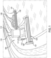
FIG. 1 illustrates a perspective view of an exemplary embodiment of an agricultural mowing assembly including an agricultural vehicle and an agricultural implement provided according to the present disclosure; -
FIG. 2 illustrates a side sectional view of the agricultural implement ofFIG. 1 ; -
FIG. 3 illustrates a perspective view of an exemplary embodiment of a disc cutter provided according to the invention including a knife in a cutting position and a spring plate in a first position; -
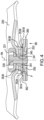
FIG. 4 illustrates a cross-sectional view of the disc cutter ofFIG. 3 taken along line 4-4; -
FIG. 5 illustrates a perspective view of the spring plate ofFIG. 4 separate from the disc cutter; -
FIG. 6 illustrates the disc cutter ofFIGS. 3-4 as the knife rotates towards an object; -
FIG. 7 illustrates a perspective view of the disc cutter ofFIGS. 3-6 after the knife has moved to a swung-in position and the spring plate is in a second position; -
FIG. 8 illustrates a cross-sectional view of the disc cutter ofFIG. 7 taken along line 8-8; -
FIG. 9 illustrates the disc cutter ofFIGS. 6-8 after centrifugal force from rotation has caused the knife to return to the cutting position and the spring plate to return to the first position; and -
FIG. 10 illustrates a perspective view of another exemplary embodiment of a spring plate provided according to the present disclosure that carries more than two protrusions. - Referring now to the drawings, and more particularly to
FIGS. 1-2 , there is shown anagricultural mowing assembly 100 which includes anagricultural vehicle 110 and at least one agricultural implement illustrated in the form of twomowing devices agricultural vehicle 110. Theagricultural mowing assembly 100 may include tandem front andrear mowing devices mowers - The
agricultural vehicle 110 generally includes achassis 111, a prime mover, wheels and/ortracks 112, and acab 113 for housing the operator. Thechassis 111 may at least partially carry the front andrear mowing devices vehicle 110 can be in the form of a tractor, self-propelled windrower, or any other desired agricultural vehicle. - The front and
rear mowing devices chassis 111 of theagricultural vehicle 110. Thefront mowing device 120, for example, may be centrally mounted onto thedriving vehicle 110 such that theagricultural vehicle 110 carries thefront mowing device 120. Therear mowing device 130 may be coupled to a tongue coupler on thechassis 111 by a pivotable tongue that can change the angular position of therear mowing device 130 relative to the forward direction of travel. As shown, themowing devices mowing devices mowing device frame reel frame cutter bar 133, aconditioner 134, e.g. at least one flail conditioner or at least twoconditioning rollers 134, and/or acrop gate 135, e.g. swath gate and/or windrow forming shields, for directing the crop material out of themowing device FIG. 2 with respect to the rear mowing device 130). The illustratedcutter bar 133 is in the form of a rotarydisc cutter bar 133 withmultiple disc cutters 136 carried by a frame of thecutter bar 133. - Referring now to
FIGS. 3-4 , one of thedisc cutters 136 is illustrated. Thedisc cutter 136 includes adisc body 320, aknife nut 340 coupled to thedisc body 320, aknife 350 having a knife opening 351 in which theknife nut 340 is disposed, and aspring plate 360. To couple theknife nut 340 to thedisc body 320, thedisc body 320 may have a disc opening 321 formed therein and abolt 330 disposed in the disc opening 321 of thedisc body 320 and anut opening 341 of theknife nut 340, but it should be appreciated that this is exemplary only and theknife nut 340 may be coupled to thedisc body 320 in other ways. When thebolt 330 is included, abolt shield 370 may also be included to protect thebolt 330 from damage during operation. Theknife 350 is configured to rotate about a rotation axis RA defined by theknife nut 340, allowing theknife 350 to rotate between a cutting position (illustrated inFIGS. 3-6 and9 ) and a swung-in position (illustrated inFIGS. 7-8 ), as will be described further herein. Thespring plate 360 is biased in a biasing direction BD upwards towards thedisc body 320 and bears on theknife 350. Thespring plate 360 may be biased in the biasing direction BD by virtue of, for example, being formed of a deformable material such as spring steel and loaded in a manner that biases thespring plate 360 in the biasing direction BD. - Referring specifically now to
FIG. 4 , andFIG. 5 as well, it can be seen that thespring plate 360 carries at least two protrusions, illustrated as a pair ofprotrusions spring plate 360 is movable between a first position (illustrated inFIGS. 3-6 and9 ) and a second position (illustrated inFIGS. 7-8 ). In the first position, thespring plate 360 bears on theknife 350 such that a plane P defined through a portion of theknife 350 extends through theprotrusions protrusions knife 350 can be held between theprotrusions spring plate 360 is in the first position to keep theknife 350 in the cutting position. -
FIGS. 6-8 illustrate what happens when theknife 350 is rotated in a rotation direction R towards anobject 600. Once theknife 350 contacts theobject 600, an overload force O is applied to theknife 350. The overload force O applied to theknife 350 forces theknife 350 over one or more of theprotrusions FIGS. 7-8 . Theknife 350 being forced over the protrusion(s) 361A, 361B causes thespring plate 360 to move to the second position, i.e., in a direction D opposite to the biasing direction BD in the illustrated embodiment. When thespring plate 360 is in the second position, theknife 350 may be in the swung-in position so the plane P extending through theknife 350 no longer extends through theprotrusions protrusions knife 350 when thespring plate 360 is in the second position but do act against theknife 350 in the biasing direction BD to keep theknife 350 from translating vertically out of its operation plane. While theknife 350 may not be able to cut crop material in the swung-in position, the overload force O e.g., when contacting theobject 600, causing movement of theknife 350 from the cutting position to the swung-in position reduces the risk of theknife 350 being substantially damage because the overload force O causes movement of theknife 350 rather than the material of theknife 350 entirely absorbing the overload force O and deforming. Therefore, theknife 350 being forced over at least one of theprotrusions knife 350 dulls, shatters, or breaks when contacting theobject 600. Thespring plate 360 with theprotrusions knife 350 moving outside of the operational plane or zone and striking and damaging other components of thedisc cutter 136. - The
protrusions spring plate 360 in a variety of ways. In some embodiments, theknife 350 includes a pair ofopposite edges protrusions edges spring plate 360 is in the first position. When thespring plate 360 is in the second position, one or both of theprotrusions edge knife 350 that the protrusion(s) 361A, 361B contacts when thespring plate 360 is in the first position. In some embodiments, both of theprotrusions respective edge knife 350 when thespring plate 360 is in the first position. Having the protrusion(s) 361A, 361B contact acorresponding edge knife 350 helps the protrusion(s) 361A, 361B stabilize theknife 350 so theknife 350 does not spontaneously rotate about the rotation axis RA during normal operation of thedisc cutter 136. - In some embodiments, the
spring plate 360 includes abearing surface 362 that bears on asurface 353 of theknife 350 in the first position and is out of contact with theknife 350 when thespring plate 360 is in the second position, as can be appreciated from comparingFIGS. 4 and8 . When thespring plate 360 is in the second position, one or both of theprotrusions surface 353 of theknife 350 rather than the bearingsurface 362 so theknife 350 does not freely rotate about the rotation axis RA but must overcome the friction between thesurface 353 and the protrusion(s) 361A, 361B to rotate. In some embodiments, thesurface 353 is a surface of theknife 350 that does not face thedisc body 320, but it should be appreciated that the surface of theknife 350 facing thedisc body 320 may also be the surface of theknife 350 that the bearingsurface 362 contacts when thespring plate 360 is in the first position. Each of theprotrusions surface 362 so theknife 350 comes out of contact with the bearingsurface 362 as theknife 350 is forced over at least one of theprotrusions protrusions surface 362 so theprotrusions surface 362. However, it should be appreciated that theprotrusions spring plate 360, e.g., to thebearing surface 362, so thespring plate 360 carries theprotrusions protrusions spring plate 360. - As best illustrated in
FIGS. 4-5 and8 , each of theprotrusions rounded surface knife 350. Each of therounded surfaces corresponding edge knife 350 and contact thecorresponding edge spring plate 360 is in the first position and theknife 350 is in the cutting position. The rounded surfaces 363A, 363B may be shaped in a variety of ways to control the overload force O that causes theknife 350 to be forced over one or both of theprotrusions rounded surfaces knife 350 to slide along the respectiverounded surface protrusions protrusions rounded surfaces knife 350 over the protrusion(s) 361A, 361B. It should thus be appreciated that theprotrusions - Referring now to
FIG. 7 andFIG. 9 specifically, it is illustrated how theknife 350 may be returned to the cutting position from the swung-in position and thespring plate 360 may be returned to the first position from the second position. As illustrated, rotation of thedisc body 320 in the rotation direction R carries theknife 350 in the rotation direction R as well. As theknife 350 rotates in the rotation direction R, a centrifugal force CF acts on theknife 350. The centrifugal force CF acts on theknife 350 in a direction that tends to cause theknife 350 to pivot about the rotation axis RA back towards the cutting position from the swung-in position. As theknife 350 pivots towards the cutting position from the swung-in position, theknife 350 may slide along one or both of theprotrusions knife 350 and the protrusion(s) 361A, 361B partially controlling how much centrifugal force CF is needed for theknife 350 to return to the cutting position. In some embodiments, the centrifugal force CF needed to return theknife 350 to the cutting position is no greater than the overload force O required to force theknife 350 over at least one of theprotrusions knife 350 to the cutting position may be less than the overload force O. When theknife 350 returns to the cutting position from the swung-in position, thespring plate 360 may momentarily come out of contact with theknife 350 and return to the first position from the second position so theknife 350 is once again in the plane P extending between theprotrusions knife 350 may automatically return to the cutting position and thespring plate 360 may automatically return to the first position due to the centrifugal force CF without the need for a user to stop operation of thedisc cutter 136. - In some embodiments, the
protrusions knife 350 defines a knife length KL that extends in parallel with the protrusion lengths LA, LB when thespring plate 360 is in the first position. As used herein, the "length" is defined as a greatest dimension between two opposed edges of theprotrusions knife 350 and "parallel" is defined as being within 5° of completely parallel. The knife length KL may also extend in parallel with the protrusion lengths LA, LB when theknife 350 is in the cutting position but not be parallel when theknife 350 is in the swung-in position. Theprotrusions protrusions protrusions knife 350 may define a knife thickness KT that is greater than the protrusion thickness TA, TB of each of theprotrusions protrusions protrusions knife 350 having a knife thickness KT that is greater than the protrusion thicknesses TA, TB differentiates theprotrusions knife 350 therein. However, it should be appreciated that in some embodiments the protrusion thickness TA, TB of one or both of theprotrusions - Referring now to
FIG. 10 , another exemplary embodiment of aspring plate 1060 carrying protrusions 1061 is illustrated. Unlike the previously describedspring plate 360, which carried twoprotrusions spring plate 1060 illustrated inFIG. 10 carries fourprotrusions protrusions 1061A are on a first side of theknife 350 bearing on one of theedges 352A of theknife 350 and the other twoprotrusions 1061B are on an opposite side of theknife 350 bearing on theother edge 352B when thespring plate 1060 is in the first position where the plane P extending through theknife 350 extends through theprotrusions knife 350, theknife 350 is forced over one or more of theprotrusions spring plate 1060 to a second position. When thespring plate 1060 is in the second position, the plane P extending through theknife 350 may not extend through theprotrusions protrusions bearing surface 1062 of thespring plate 1060. In other respects, thespring plate 1060 may be similar to the previously describedspring plate 360. - From the foregoing, it should be appreciated that the
spring plate protrusions knife 350 in a desired horizontal plane P during normal operation of thedisc cutter 136. When theknife 350 contacts anobject 600, the overload force O applied to theknife 350 can force theknife 350 over one or more of theprotrusions knife 350. Theknife 350 also tends to stay in the operating plane due to thespring plate knife 350 in the biasing direction BD even when thespring plate knife 350 can then return theknife 350 to the cutting position without any intervention or stoppage of thedisc cutter 136. It should thus be appreciated that thespring plate knife 350 in a manner that does not substantially hinder operation of thedisc cutter 136. - These and other advantages of the present invention will be apparent to those skilled in the art from the foregoing specification. Accordingly, it is to be recognized by those skilled in the art that changes or modifications may be made to the above-described embodiments without departing from the broad inventive concepts of the invention.
Claims (9)
- A disc cutter (136) for an agricultural implement, comprising:a disc body (320);a knife nut (340) coupled to the disc body (320);a knife (350) comprising a knife opening (351) in which the knife nut (340) is disposed, the knife (350) being configured to rotate about a rotation axis (RA) defined by the knife nut (340); anda spring plate (360) carrying at least two protrusions (361A,361B), the spring plate (360) being biased towards the disc body (320) such that in a first position the spring plate (360) bears on the knife (350) so a plane (P) defined through a portion of the knife (350) extends through the protrusions (361A,361B) until an overload force applied to the knife (350) forces the knife (350) over at least one of the protrusions (361A,361B) and moves the spring plate (360) to a second position.
- The disc cutter (136) of claim 1, wherein the knife (350) comprises a pair of opposite edges (352A, 352B) and at least one of the protrusions (361A,361B) bears on a respective one of the edges (352A, 352B) when the spring plate (360) is in the first position.
- The disc cutter (136) of claim 1, wherein the spring plate (360) comprises a bearing surface (362) that bears on a surface of the knife (350) in the first position and is out of contact with the surface of the knife (350) when the spring plate (360) is in the second position.
- The disc cutter (136) of claim 3, wherein each of the protrusions (361A,361B) extends from the bearing surface (362).
- The disc cutter (136) of claim 1, wherein at least one of the protrusions comprises (361A,361B) a rounded surface (363A, 363B) facing the knife (350).
- The disc cutter (136) of claim 1, wherein the protrusions (361A,361B) each define a respective protrusion length (LA,LB) and the knife (350) defines a knife length (KL) that extends in parallel with the protrusion length (LA,LB) when the spring plate (360) is in the first position.
- The disc cutter (136) of claim 1, wherein each of the protrusions (361A,361B) defines a respective protrusion thickness (TA,TB) and the knife (350) defines a knife thickness (KT) that is greater than the protrusion thickness (TA,TB) of each of the protrusions (361A,361B.
- A cutter bar (133) for an agricultural implement, comprising:a frame (121,131); anda plurality of disc cutters (136) carried by the frame (121,131), at least one of the disc cutters (136) comprising the disk cutter (136) of any preceding claim.
- An agricultural mowing assembly (100), comprising:an agricultural vehicle (110); andan agricultural implement coupled to the agricultural vehicle (110), the agricultural implement comprising a cutter bar (133) as claimed in claim 8.
Applications Claiming Priority (1)
| Application Number | Priority Date | Filing Date | Title |
|---|---|---|---|
| US18/074,652 US12593750B2 (en) | 2022-12-05 | 2022-12-05 | Agricultural disc mower with knife-retaining spring plate |
Publications (2)
| Publication Number | Publication Date |
|---|---|
| EP4381930A1 true EP4381930A1 (en) | 2024-06-12 |
| EP4381930B1 EP4381930B1 (en) | 2025-07-16 |
Family
ID=89119484
Family Applications (1)
| Application Number | Title | Priority Date | Filing Date |
|---|---|---|---|
| EP23214367.7A Active EP4381930B1 (en) | 2022-12-05 | 2023-12-05 | Agricultural disc mower with knife-retaining spring plate |
Country Status (2)
| Country | Link |
|---|---|
| US (1) | US12593750B2 (en) |
| EP (1) | EP4381930B1 (en) |
Citations (5)
| Publication number | Priority date | Publication date | Assignee | Title |
|---|---|---|---|---|
| US6829878B1 (en) * | 2004-03-29 | 2004-12-14 | Cnh America Llc | Quick change disc knife mounting mechanism |
| US20140126952A1 (en) * | 2012-11-02 | 2014-05-08 | Ii Jeffrey Fay | Knife nut for quick-change knives on a disc mower |
| US8857038B2 (en) * | 2011-09-07 | 2014-10-14 | Cnh Industrial America Llc | Disc cutterbar quick-change knife with retaining pin assembly |
| PL67473Y1 (en) * | 2012-04-18 | 2014-11-28 | Samasz Spółka Z Ograniczoną Odpowiedzialnością | Cutter handle for disc mower |
| US20190373810A1 (en) * | 2018-06-08 | 2019-12-12 | Cnh Industrial America Llc | Hybrid disc cutting system for an agricultural vehicle |
Family Cites Families (7)
| Publication number | Priority date | Publication date | Assignee | Title |
|---|---|---|---|---|
| BE789302A (en) * | 1971-09-28 | 1973-01-15 | Victa Ltd | MOUNTING KIT FOR CUTTING BLADE OF ROTARY MOWER TYPE LAWN MOWER |
| CA1005648A (en) * | 1974-05-10 | 1977-02-22 | International Harvester Company | Cutter blade mounting for a rotary mower |
| US20050193706A1 (en) * | 2003-03-12 | 2005-09-08 | Kent Thompson | Mowing device, a knife adapter for such a mowing device and a retainer for such a mowing device |
| US20100101201A1 (en) | 2008-10-28 | 2010-04-29 | Bryan Ray Yanke | Knife holder for a rotary disk cutterbar |
| US8776489B2 (en) * | 2012-03-21 | 2014-07-15 | Deere & Company | Mowing cutter disc having a mowing blade and a holder |
| US9545053B2 (en) | 2014-04-25 | 2017-01-17 | Cnh Industrial America Llc | Spring plate configured to overlap with asymmetric/eccentric quick change knife nut for proper assembly |
| DE102015214051A1 (en) * | 2015-07-24 | 2017-01-26 | Deere & Company | Knife rotor for a mowing device Clamping tool and mowing device with such |
-
2022
- 2022-12-05 US US18/074,652 patent/US12593750B2/en active Active
-
2023
- 2023-12-05 EP EP23214367.7A patent/EP4381930B1/en active Active
Patent Citations (5)
| Publication number | Priority date | Publication date | Assignee | Title |
|---|---|---|---|---|
| US6829878B1 (en) * | 2004-03-29 | 2004-12-14 | Cnh America Llc | Quick change disc knife mounting mechanism |
| US8857038B2 (en) * | 2011-09-07 | 2014-10-14 | Cnh Industrial America Llc | Disc cutterbar quick-change knife with retaining pin assembly |
| PL67473Y1 (en) * | 2012-04-18 | 2014-11-28 | Samasz Spółka Z Ograniczoną Odpowiedzialnością | Cutter handle for disc mower |
| US20140126952A1 (en) * | 2012-11-02 | 2014-05-08 | Ii Jeffrey Fay | Knife nut for quick-change knives on a disc mower |
| US20190373810A1 (en) * | 2018-06-08 | 2019-12-12 | Cnh Industrial America Llc | Hybrid disc cutting system for an agricultural vehicle |
Also Published As
| Publication number | Publication date |
|---|---|
| EP4381930B1 (en) | 2025-07-16 |
| US12593750B2 (en) | 2026-04-07 |
| US20240180077A1 (en) | 2024-06-06 |
Similar Documents
| Publication | Publication Date | Title |
|---|---|---|
| US4330982A (en) | Mowing device | |
| US4694640A (en) | Mowing machine for cutting hay and cereal grass | |
| US9861036B2 (en) | Skid shoe for a header of an agricultural harvester | |
| EP0913078A1 (en) | Mower device for lawnmower | |
| US11963479B2 (en) | Blades and knives for agricultural machines having a toothing being varied along a length | |
| US4304088A (en) | Rotary mower with end-to-end connected blade-carrier supports | |
| US10820499B2 (en) | Hybrid disc cutting system having a knife mount for an agricultural vehicle | |
| EP4381930B1 (en) | Agricultural disc mower with knife-retaining spring plate | |
| US6050075A (en) | Lateral float apparatus for windrow pickup attachment | |
| US3261151A (en) | Crop chopper knife | |
| CA2531189A1 (en) | Blade for a crop harvesting header with rotary disks | |
| EP4385305A1 (en) | Agricultural disc mower with knives, a spring plate, and a knife nut that acts as a stop | |
| US3963183A (en) | Resharpenable recutter screen for forage harvester | |
| US3338036A (en) | Hay harvesting machine | |
| US20190373809A1 (en) | Rotary sickle cutting system for an agricultural vehicle | |
| EP4381931B1 (en) | Agricultural disc mower with fully reversible knife | |
| US3699757A (en) | Belt carried cutters and mounting means therefore | |
| EP3695704B1 (en) | An impeller conditioner including a tine device with limited lateral movement | |
| US6996965B2 (en) | Processing element for agricultural machines | |
| EP0908088A1 (en) | Lateral float apparatus for windrow pick-up attachment | |
| US6067783A (en) | Vegetation deflecting device for a multi-blade rotary mower | |
| US12575490B2 (en) | Agricultural rotary disc mower | |
| US20180295777A1 (en) | Header with a crop divider disc | |
| US12290025B2 (en) | Stalk conditioner | |
| US20240099194A1 (en) | Mower-conditioner having fins on control surfaces |
Legal Events
| Date | Code | Title | Description |
|---|---|---|---|
| PUAI | Public reference made under article 153(3) epc to a published international application that has entered the european phase |
Free format text: ORIGINAL CODE: 0009012 |
|
| STAA | Information on the status of an ep patent application or granted ep patent |
Free format text: STATUS: THE APPLICATION HAS BEEN PUBLISHED |
|
| AK | Designated contracting states |
Kind code of ref document: A1 Designated state(s): AL AT BE BG CH CY CZ DE DK EE ES FI FR GB GR HR HU IE IS IT LI LT LU LV MC ME MK MT NL NO PL PT RO RS SE SI SK SM TR |
|
| STAA | Information on the status of an ep patent application or granted ep patent |
Free format text: STATUS: REQUEST FOR EXAMINATION WAS MADE |
|
| 17P | Request for examination filed |
Effective date: 20241212 |
|
| GRAP | Despatch of communication of intention to grant a patent |
Free format text: ORIGINAL CODE: EPIDOSNIGR1 |
|
| STAA | Information on the status of an ep patent application or granted ep patent |
Free format text: STATUS: GRANT OF PATENT IS INTENDED |
|
| RIC1 | Information provided on ipc code assigned before grant |
Ipc: A01D 34/82 20060101ALI20250205BHEP Ipc: A01D 43/10 20060101ALI20250205BHEP Ipc: A01D 34/73 20060101ALI20250205BHEP Ipc: A01D 34/66 20060101AFI20250205BHEP |
|
| INTG | Intention to grant announced |
Effective date: 20250217 |
|
| GRAS | Grant fee paid |
Free format text: ORIGINAL CODE: EPIDOSNIGR3 |
|
| GRAA | (expected) grant |
Free format text: ORIGINAL CODE: 0009210 |
|
| STAA | Information on the status of an ep patent application or granted ep patent |
Free format text: STATUS: THE PATENT HAS BEEN GRANTED |
|
| AK | Designated contracting states |
Kind code of ref document: B1 Designated state(s): AL AT BE BG CH CY CZ DE DK EE ES FI FR GB GR HR HU IE IS IT LI LT LU LV MC ME MK MT NL NO PL PT RO RS SE SI SK SM TR |
|
| REG | Reference to a national code |
Ref country code: GB Ref legal event code: FG4D |
|
| REG | Reference to a national code |
Ref country code: CH Ref legal event code: EP Ref country code: DE Ref legal event code: R096 Ref document number: 602023004875 Country of ref document: DE |
|
| REG | Reference to a national code |
Ref country code: IE Ref legal event code: FG4D |
|
| REG | Reference to a national code |
Ref country code: NL Ref legal event code: MP Effective date: 20250716 |
|
| PG25 | Lapsed in a contracting state [announced via postgrant information from national office to epo] |
Ref country code: PT Free format text: LAPSE BECAUSE OF FAILURE TO SUBMIT A TRANSLATION OF THE DESCRIPTION OR TO PAY THE FEE WITHIN THE PRESCRIBED TIME-LIMIT Effective date: 20251117 |
|
| PG25 | Lapsed in a contracting state [announced via postgrant information from national office to epo] |
Ref country code: NL Free format text: LAPSE BECAUSE OF FAILURE TO SUBMIT A TRANSLATION OF THE DESCRIPTION OR TO PAY THE FEE WITHIN THE PRESCRIBED TIME-LIMIT Effective date: 20250716 |
|
| REG | Reference to a national code |
Ref country code: AT Ref legal event code: MK05 Ref document number: 1813147 Country of ref document: AT Kind code of ref document: T Effective date: 20250716 |
|
| PG25 | Lapsed in a contracting state [announced via postgrant information from national office to epo] |
Ref country code: IS Free format text: LAPSE BECAUSE OF FAILURE TO SUBMIT A TRANSLATION OF THE DESCRIPTION OR TO PAY THE FEE WITHIN THE PRESCRIBED TIME-LIMIT Effective date: 20251116 |
|
| PG25 | Lapsed in a contracting state [announced via postgrant information from national office to epo] |
Ref country code: NO Free format text: LAPSE BECAUSE OF FAILURE TO SUBMIT A TRANSLATION OF THE DESCRIPTION OR TO PAY THE FEE WITHIN THE PRESCRIBED TIME-LIMIT Effective date: 20251016 |
|
| REG | Reference to a national code |
Ref country code: LT Ref legal event code: MG9D |
|
| PG25 | Lapsed in a contracting state [announced via postgrant information from national office to epo] |
Ref country code: AT Free format text: LAPSE BECAUSE OF FAILURE TO SUBMIT A TRANSLATION OF THE DESCRIPTION OR TO PAY THE FEE WITHIN THE PRESCRIBED TIME-LIMIT Effective date: 20250716 |
|
| PG25 | Lapsed in a contracting state [announced via postgrant information from national office to epo] |
Ref country code: FI Free format text: LAPSE BECAUSE OF FAILURE TO SUBMIT A TRANSLATION OF THE DESCRIPTION OR TO PAY THE FEE WITHIN THE PRESCRIBED TIME-LIMIT Effective date: 20250716 |
|
| PG25 | Lapsed in a contracting state [announced via postgrant information from national office to epo] |
Ref country code: HR Free format text: LAPSE BECAUSE OF FAILURE TO SUBMIT A TRANSLATION OF THE DESCRIPTION OR TO PAY THE FEE WITHIN THE PRESCRIBED TIME-LIMIT Effective date: 20250716 |
|
| PGFP | Annual fee paid to national office [announced via postgrant information from national office to epo] |
Ref country code: FR Payment date: 20251223 Year of fee payment: 3 |
|
| PG25 | Lapsed in a contracting state [announced via postgrant information from national office to epo] |
Ref country code: GR Free format text: LAPSE BECAUSE OF FAILURE TO SUBMIT A TRANSLATION OF THE DESCRIPTION OR TO PAY THE FEE WITHIN THE PRESCRIBED TIME-LIMIT Effective date: 20251017 |
|
| PG25 | Lapsed in a contracting state [announced via postgrant information from national office to epo] |
Ref country code: SE Free format text: LAPSE BECAUSE OF FAILURE TO SUBMIT A TRANSLATION OF THE DESCRIPTION OR TO PAY THE FEE WITHIN THE PRESCRIBED TIME-LIMIT Effective date: 20250716 |
|
| PG25 | Lapsed in a contracting state [announced via postgrant information from national office to epo] |
Ref country code: LV Free format text: LAPSE BECAUSE OF FAILURE TO SUBMIT A TRANSLATION OF THE DESCRIPTION OR TO PAY THE FEE WITHIN THE PRESCRIBED TIME-LIMIT Effective date: 20250716 |
|
| PG25 | Lapsed in a contracting state [announced via postgrant information from national office to epo] |
Ref country code: PL Free format text: LAPSE BECAUSE OF FAILURE TO SUBMIT A TRANSLATION OF THE DESCRIPTION OR TO PAY THE FEE WITHIN THE PRESCRIBED TIME-LIMIT Effective date: 20250716 Ref country code: BG Free format text: LAPSE BECAUSE OF FAILURE TO SUBMIT A TRANSLATION OF THE DESCRIPTION OR TO PAY THE FEE WITHIN THE PRESCRIBED TIME-LIMIT Effective date: 20250716 |
|
| PG25 | Lapsed in a contracting state [announced via postgrant information from national office to epo] |
Ref country code: RS Free format text: LAPSE BECAUSE OF FAILURE TO SUBMIT A TRANSLATION OF THE DESCRIPTION OR TO PAY THE FEE WITHIN THE PRESCRIBED TIME-LIMIT Effective date: 20251016 |
|
| PG25 | Lapsed in a contracting state [announced via postgrant information from national office to epo] |
Ref country code: ES Free format text: LAPSE BECAUSE OF FAILURE TO SUBMIT A TRANSLATION OF THE DESCRIPTION OR TO PAY THE FEE WITHIN THE PRESCRIBED TIME-LIMIT Effective date: 20250716 |
|
| PG25 | Lapsed in a contracting state [announced via postgrant information from national office to epo] |
Ref country code: RO Free format text: LAPSE BECAUSE OF FAILURE TO SUBMIT A TRANSLATION OF THE DESCRIPTION OR TO PAY THE FEE WITHIN THE PRESCRIBED TIME-LIMIT Effective date: 20250716 |
|
| PG25 | Lapsed in a contracting state [announced via postgrant information from national office to epo] |
Ref country code: SM Free format text: LAPSE BECAUSE OF FAILURE TO SUBMIT A TRANSLATION OF THE DESCRIPTION OR TO PAY THE FEE WITHIN THE PRESCRIBED TIME-LIMIT Effective date: 20250716 |
|
| PG25 | Lapsed in a contracting state [announced via postgrant information from national office to epo] |
Ref country code: DK Free format text: LAPSE BECAUSE OF FAILURE TO SUBMIT A TRANSLATION OF THE DESCRIPTION OR TO PAY THE FEE WITHIN THE PRESCRIBED TIME-LIMIT Effective date: 20250716 |
|
| PGFP | Annual fee paid to national office [announced via postgrant information from national office to epo] |
Ref country code: DE Payment date: 20251229 Year of fee payment: 3 |
|
| PGFP | Annual fee paid to national office [announced via postgrant information from national office to epo] |
Ref country code: IT Payment date: 20251231 Year of fee payment: 3 |
|
| PG25 | Lapsed in a contracting state [announced via postgrant information from national office to epo] |
Ref country code: CZ Free format text: LAPSE BECAUSE OF FAILURE TO SUBMIT A TRANSLATION OF THE DESCRIPTION OR TO PAY THE FEE WITHIN THE PRESCRIBED TIME-LIMIT Effective date: 20250716 |
|
| PG25 | Lapsed in a contracting state [announced via postgrant information from national office to epo] |
Ref country code: EE Free format text: LAPSE BECAUSE OF FAILURE TO SUBMIT A TRANSLATION OF THE DESCRIPTION OR TO PAY THE FEE WITHIN THE PRESCRIBED TIME-LIMIT Effective date: 20250716 Ref country code: SK Free format text: LAPSE BECAUSE OF FAILURE TO SUBMIT A TRANSLATION OF THE DESCRIPTION OR TO PAY THE FEE WITHIN THE PRESCRIBED TIME-LIMIT Effective date: 20250716 |