EP4379944A1 - Battery module busbar, battery module and battery pack - Google Patents
Battery module busbar, battery module and battery pack Download PDFInfo
- Publication number
- EP4379944A1 EP4379944A1 EP22848543.9A EP22848543A EP4379944A1 EP 4379944 A1 EP4379944 A1 EP 4379944A1 EP 22848543 A EP22848543 A EP 22848543A EP 4379944 A1 EP4379944 A1 EP 4379944A1
- Authority
- EP
- European Patent Office
- Prior art keywords
- busbar
- battery module
- lower casing
- upper casing
- water conduits
- Prior art date
- Legal status (The legal status is an assumption and is not a legal conclusion. Google has not performed a legal analysis and makes no representation as to the accuracy of the status listed.)
- Pending
Links
- XLYOFNOQVPJJNP-UHFFFAOYSA-N water Substances O XLYOFNOQVPJJNP-UHFFFAOYSA-N 0.000 claims abstract description 21
- 238000005452 bending Methods 0.000 claims abstract description 11
- 230000007704 transition Effects 0.000 claims description 9
- PXHVJJICTQNCMI-UHFFFAOYSA-N Nickel Chemical compound [Ni] PXHVJJICTQNCMI-UHFFFAOYSA-N 0.000 claims description 8
- 238000000034 method Methods 0.000 claims description 8
- 239000000463 material Substances 0.000 claims description 7
- 229910052759 nickel Inorganic materials 0.000 claims description 4
- XAGFODPZIPBFFR-UHFFFAOYSA-N aluminium Chemical compound [Al] XAGFODPZIPBFFR-UHFFFAOYSA-N 0.000 claims description 3
- 229910052782 aluminium Inorganic materials 0.000 claims description 3
- 238000002955 isolation Methods 0.000 abstract description 5
- 238000010292 electrical insulation Methods 0.000 description 3
- 238000005070 sampling Methods 0.000 description 3
- 230000000694 effects Effects 0.000 description 2
- 238000009413 insulation Methods 0.000 description 2
- 238000012986 modification Methods 0.000 description 2
- 230000004048 modification Effects 0.000 description 2
- 230000005540 biological transmission Effects 0.000 description 1
- 238000005516 engineering process Methods 0.000 description 1
- 238000009434 installation Methods 0.000 description 1
- 230000013011 mating Effects 0.000 description 1
- 238000003466 welding Methods 0.000 description 1
Images

Classifications
-
- H—ELECTRICITY
- H01—ELECTRIC ELEMENTS
- H01M—PROCESSES OR MEANS, e.g. BATTERIES, FOR THE DIRECT CONVERSION OF CHEMICAL ENERGY INTO ELECTRICAL ENERGY
- H01M50/00—Constructional details or processes of manufacture of the non-active parts of electrochemical cells other than fuel cells, e.g. hybrid cells
- H01M50/50—Current conducting connections for cells or batteries
- H01M50/502—Interconnectors for connecting terminals of adjacent batteries; Interconnectors for connecting cells outside a battery casing
- H01M50/503—Interconnectors for connecting terminals of adjacent batteries; Interconnectors for connecting cells outside a battery casing characterised by the shape of the interconnectors
-
- H—ELECTRICITY
- H01—ELECTRIC ELEMENTS
- H01M—PROCESSES OR MEANS, e.g. BATTERIES, FOR THE DIRECT CONVERSION OF CHEMICAL ENERGY INTO ELECTRICAL ENERGY
- H01M10/00—Secondary cells; Manufacture thereof
- H01M10/60—Heating or cooling; Temperature control
- H01M10/61—Types of temperature control
- H01M10/613—Cooling or keeping cold
-
- H—ELECTRICITY
- H01—ELECTRIC ELEMENTS
- H01M—PROCESSES OR MEANS, e.g. BATTERIES, FOR THE DIRECT CONVERSION OF CHEMICAL ENERGY INTO ELECTRICAL ENERGY
- H01M10/00—Secondary cells; Manufacture thereof
- H01M10/60—Heating or cooling; Temperature control
- H01M10/65—Means for temperature control structurally associated with the cells
- H01M10/655—Solid structures for heat exchange or heat conduction
- H01M10/6556—Solid parts with flow channel passages or pipes for heat exchange
- H01M10/6557—Solid parts with flow channel passages or pipes for heat exchange arranged between the cells
-
- H—ELECTRICITY
- H01—ELECTRIC ELEMENTS
- H01M—PROCESSES OR MEANS, e.g. BATTERIES, FOR THE DIRECT CONVERSION OF CHEMICAL ENERGY INTO ELECTRICAL ENERGY
- H01M10/00—Secondary cells; Manufacture thereof
- H01M10/60—Heating or cooling; Temperature control
- H01M10/65—Means for temperature control structurally associated with the cells
- H01M10/656—Means for temperature control structurally associated with the cells characterised by the type of heat-exchange fluid
- H01M10/6567—Liquids
-
- H—ELECTRICITY
- H01—ELECTRIC ELEMENTS
- H01M—PROCESSES OR MEANS, e.g. BATTERIES, FOR THE DIRECT CONVERSION OF CHEMICAL ENERGY INTO ELECTRICAL ENERGY
- H01M50/00—Constructional details or processes of manufacture of the non-active parts of electrochemical cells other than fuel cells, e.g. hybrid cells
- H01M50/50—Current conducting connections for cells or batteries
- H01M50/502—Interconnectors for connecting terminals of adjacent batteries; Interconnectors for connecting cells outside a battery casing
- H01M50/505—Interconnectors for connecting terminals of adjacent batteries; Interconnectors for connecting cells outside a battery casing comprising a single busbar
-
- H—ELECTRICITY
- H01—ELECTRIC ELEMENTS
- H01M—PROCESSES OR MEANS, e.g. BATTERIES, FOR THE DIRECT CONVERSION OF CHEMICAL ENERGY INTO ELECTRICAL ENERGY
- H01M50/00—Constructional details or processes of manufacture of the non-active parts of electrochemical cells other than fuel cells, e.g. hybrid cells
- H01M50/50—Current conducting connections for cells or batteries
- H01M50/502—Interconnectors for connecting terminals of adjacent batteries; Interconnectors for connecting cells outside a battery casing
- H01M50/514—Methods for interconnecting adjacent batteries or cells
- H01M50/516—Methods for interconnecting adjacent batteries or cells by welding, soldering or brazing
-
- H—ELECTRICITY
- H01—ELECTRIC ELEMENTS
- H01M—PROCESSES OR MEANS, e.g. BATTERIES, FOR THE DIRECT CONVERSION OF CHEMICAL ENERGY INTO ELECTRICAL ENERGY
- H01M50/00—Constructional details or processes of manufacture of the non-active parts of electrochemical cells other than fuel cells, e.g. hybrid cells
- H01M50/50—Current conducting connections for cells or batteries
- H01M50/502—Interconnectors for connecting terminals of adjacent batteries; Interconnectors for connecting cells outside a battery casing
- H01M50/521—Interconnectors for connecting terminals of adjacent batteries; Interconnectors for connecting cells outside a battery casing characterised by the material
- H01M50/526—Interconnectors for connecting terminals of adjacent batteries; Interconnectors for connecting cells outside a battery casing characterised by the material having a layered structure
-
- H—ELECTRICITY
- H01—ELECTRIC ELEMENTS
- H01M—PROCESSES OR MEANS, e.g. BATTERIES, FOR THE DIRECT CONVERSION OF CHEMICAL ENERGY INTO ELECTRICAL ENERGY
- H01M50/00—Constructional details or processes of manufacture of the non-active parts of electrochemical cells other than fuel cells, e.g. hybrid cells
- H01M50/50—Current conducting connections for cells or batteries
- H01M50/572—Means for preventing undesired use or discharge
- H01M50/584—Means for preventing undesired use or discharge for preventing incorrect connections inside or outside the batteries
- H01M50/588—Means for preventing undesired use or discharge for preventing incorrect connections inside or outside the batteries outside the batteries, e.g. incorrect connections of terminals or busbars
-
- H—ELECTRICITY
- H01—ELECTRIC ELEMENTS
- H01M—PROCESSES OR MEANS, e.g. BATTERIES, FOR THE DIRECT CONVERSION OF CHEMICAL ENERGY INTO ELECTRICAL ENERGY
- H01M50/00—Constructional details or processes of manufacture of the non-active parts of electrochemical cells other than fuel cells, e.g. hybrid cells
- H01M50/50—Current conducting connections for cells or batteries
- H01M50/572—Means for preventing undesired use or discharge
- H01M50/584—Means for preventing undesired use or discharge for preventing incorrect connections inside or outside the batteries
- H01M50/59—Means for preventing undesired use or discharge for preventing incorrect connections inside or outside the batteries characterised by the protection means
- H01M50/593—Spacers; Insulating plates
-
- Y—GENERAL TAGGING OF NEW TECHNOLOGICAL DEVELOPMENTS; GENERAL TAGGING OF CROSS-SECTIONAL TECHNOLOGIES SPANNING OVER SEVERAL SECTIONS OF THE IPC; TECHNICAL SUBJECTS COVERED BY FORMER USPC CROSS-REFERENCE ART COLLECTIONS [XRACs] AND DIGESTS
- Y02—TECHNOLOGIES OR APPLICATIONS FOR MITIGATION OR ADAPTATION AGAINST CLIMATE CHANGE
- Y02E—REDUCTION OF GREENHOUSE GAS [GHG] EMISSIONS, RELATED TO ENERGY GENERATION, TRANSMISSION OR DISTRIBUTION
- Y02E60/00—Enabling technologies; Technologies with a potential or indirect contribution to GHG emissions mitigation
- Y02E60/10—Energy storage using batteries
Definitions
- the present disclosure relates to the field of battery technology, in specifically to a battery module busbar, a battery module and a battery pack.
- a battery module sampling assembly is generally constituted by plastic isolation plate, FPC and busbar etc.
- the busbar serves as a connecting bridge between one battery cell and another so as to play a role of electric current transmission.
- the busbar is necessary to be electrically insulated from the surrounding non-conductive metallic parts to avoid the safety risks such as short circuit etc.
- a sufficiently large gap is pre-set between the busbar and the non-conductive metallic parts or a plastic support is provided to separate them from each other in order to ensure that there is no contact between the busbar and the non-conductive metallic parts.
- a plastic support is provided to separate them from each other in order to ensure that there is no contact between the busbar and the non-conductive metallic parts.
- a first object of the present disclosure is to provide a battery module busbar which is possible to achieve electrical isolation of the busbar between modules inside a limited arrangement space.
- a second object of the present disclosure is to provide a battery module which adopts the battery module busbar provided by the present disclosure.
- a third object of the present disclosure is to provide a battery pack which comprises the battery module provided by the present disclosure.
- the present disclosure provides a battery module busbar in which the battery module has a U-shaped end plate and above a bottom wall of which water conduits are arranged.
- the battery module busbar comprises an upper casing, a busbar body and a lower casing which are arranged successively from top to bottom, wherein the busbar body comprises a U-shaped segment opening towards the water conduits and extension segments formed by bending outside from side plate faces of the U-shaped segment, said extension segments are used for connecting with cell poles.
- the upper casing and the lower casing are both configured into a U-shape so as to fit with the U-shaped segment of the busbar body.
- a gap is provided between the upper casing and the water conduits, and side plate faces of the lower casing are fitted with side walls of the end plate.
- the extension segments each comprises a horizontal segment and a transition segment which connects the horizontal segment and the U-shaped segment, and the cell poles are welded to the horizontal segment.
- side walls of the upper casing and the lower casing are bending outside to form bending segments which fit with the transition segments.
- the upper casing and the lower casing are fixedly connected by snap-fit so as to enclose the U-shaped segment therebetween.
- an end portion of each of the extension segments which is far away from the U-shaped segment has a recess formed thereon for placing a nickel sheet.
- each of the side plate faces a plurality of spaced apart ribs which extend along their height direction, said ribs each has a cross section which tapering from top to bottom.
- the upper casing and the lower casing are both made of a material of polylaurylamide, and the busbar body is made of a material of aluminum.
- a distance between the upper casing and the water conduits is 3 to 5mm.
- a battery module which comprises an end plate and a busbar arranged on the end plate for connecting with cell poles, said busbar is the above mentioned battery module busbar.
- a battery pack which comprises the above mentioned battery module.
- an electrical insulation effect is achieved by the upper casing and the lower casing enclose therebetween the busbar body for connecting with cell poles, and use of the space between the end plate and the water conduits can be maximized thanks to the design of the shape of the busbar in which the side plate faces of the lower casing are fitted with the side walls of the end plate, so as to ensure that no relative movement and thus no wear will be occurred between the busbar and the end plate during vibration, and friction is also avoided by the certain gap between the upper casing and the water conduits.
- the above arrangement is able to achieve electrical insulated isolation of the busbar between modules inside a limited arrangement space.
- the present disclosure provides a battery module busbar.
- the battery module has a U-shaped end plate 1, above a bottom wall of which water conduits 2 or other non-conductive metallic parts are arranged.
- the battery module busbar comprises an upper casing 4, a busbar body 3 and a lower casing 5 which are arranged successively from top to bottom, wherein the busbar body 3 comprises a U-shaped segment 31 opening towards the water conduits 2 and extension segments 32 formed by bending outside from side plate faces of the U-shaped segment 31, said extension segments 32 are used for connecting with cell poles.
- the upper casing 4 and the lower casings 5 are each configured into a U-shape so as to fit with the U-shaped segment 31 of the busbar body 3.
- a gap is provided between the upper casing 4 and the water conduits 2, and side plate faces of the lower casing 5 are fitted with side walls of the end plate 1.
- an electrical insulation effect is achieved by the upper casing 4 and the lower casing 5 enclose therebetween the busbar body 3 for connecting with cell poles, and use of the space between the end plate 1 and the water conduits 2 can be maximized thanks to the design of the shape of the busbar in which the side plate faces of the lower casing 5 are fitted with the side walls of the end plate 1, so as to ensure that no relative movement and thus no wear will be occurred between the busbar and the end plate 1 during vibration, and friction is also avoided by the certain gap between the upper casing 4 and the water conduits 2.
- the above arrangement is able to achieve electrical insulated isolation of the busbar between modules inside a limited arrangement space.
- the extension segments 32 may comprise a horizontal segment 321 and a transition segment 322 which connects the horizontal segment 321 and the U-shaped segment 31, wherein the transition segment 322 may have an inclined arrangement and the cell poles may be connected to the horizontal segment 321 by means of laser welding process.
- side walls of the upper casing 4 and the lower casing 5 are bending outside to form bending segments which fit with the transition segments 322 and arranging above side walls of the end plate 1 such that an insulation protection of the transition segments 322 can be achieved by means of the bending segments.
- the upper casing 4 and the lower casing 5 are fixedly connected by snap-fit so as to enclose the U-shaped segment 31 therebetween.
- one of the upper casing 4 and the lower casing 5 is provided with a plurality of spaced apart slots on both of its front and back ends, and front and back ends of the other are provided with a plurality of projections mating with the respectively slots.
- an end portion of each of the extension segments 32 which is far away from the U-shaped segment 31 has a recess 323 formed thereon for placing a nickel sheet in the recess 323, so as to conduct voltage temperature sampling.
- the nickel sheet may be welded inside the recess 323 such that it does not interfere with an upper cover of the battery module and save space.
- a depth of the recess 323 is optionally 0.3mm.
- ribs 51 each has a cross section which tapering from top to bottom to guide the mounting of the busbar so as to facilitate the assembly of the busbar on the battery module, as well as making the connection of the lower casing 5 and the end plate 1 more tight.
- the upper casing 4 and the lower casing 5 may both made of a material of polylaurylamide which has good insulating property, wear resistance and toughness, and the material of the busbar body 3 may be aluminum. Note that the materials of busbar body 3, upper casing 4 and lower casing 5 may be arbitrarily selected as required and all of them are within the scope of the present disclosure.
- a distance between the upper casing 4 and the water conduits 2 is 3 to 5mm, and which in the embodiment of the present disclosure is 4.6mm.
- a battery module which comprises an end plate 1 and a busbar arranged on the end plate 1 for connecting with cell poles.
- Said busbar is the battery module busbar provided by the present disclosure, which has the same advantages as the above mentioned battery module busbar relative to the prior arts, so details thereof are not repeated hereafter.
- a battery pack which comprises the battery module provided by the present disclosure.
- the battery pack has the same advantages as the above mentioned battery module busbar and the battery module relative to the prior arts, so details thereof are not repeated hereafter.
Landscapes
- Chemical & Material Sciences (AREA)
- Chemical Kinetics & Catalysis (AREA)
- Electrochemistry (AREA)
- General Chemical & Material Sciences (AREA)
- Engineering & Computer Science (AREA)
- Manufacturing & Machinery (AREA)
- Connection Of Batteries Or Terminals (AREA)
- Battery Mounting, Suspending (AREA)
Abstract
Description
- This application claims priority to
Chinese patent application No. 202121774812.3 filed on July 30, 2021 - The present disclosure relates to the field of battery technology, in specifically to a battery module busbar, a battery module and a battery pack.
- A battery module sampling assembly is generally constituted by plastic isolation plate, FPC and busbar etc. The busbar serves as a connecting bridge between one battery cell and another so as to play a role of electric current transmission. The busbar is necessary to be electrically insulated from the surrounding non-conductive metallic parts to avoid the safety risks such as short circuit etc.
- In related arts, a sufficiently large gap is pre-set between the busbar and the non-conductive metallic parts or a plastic support is provided to separate them from each other in order to ensure that there is no contact between the busbar and the non-conductive metallic parts. Presently, since arrangement space of the module sampling assembly and thus the distance between the busbar and the non-conductive metallic parts becomes more and more smaller, it is hard to achieve electrical insulation by only pre-setting the gap or separating by means of the plastic support. In addition, there are solutions which sheathing the surface of the busbar with a heat shrink tube, which heat shrink tube however has a relatively poor wear resistance and thus more susceptible to scratches and causing insulation failure as a result, and also the heat shrink tube will rub against the metallic parts in case of the smaller gap and thus causing wear of the heat shrink tube.
- A first object of the present disclosure is to provide a battery module busbar which is possible to achieve electrical isolation of the busbar between modules inside a limited arrangement space.
- A second object of the present disclosure is to provide a battery module which adopts the battery module busbar provided by the present disclosure.
- A third object of the present disclosure is to provide a battery pack which comprises the battery module provided by the present disclosure.
- To achieve the above objects, the present disclosure provides a battery module busbar in which the battery module has a U-shaped end plate and above a bottom wall of which water conduits are arranged. The battery module busbar comprises an upper casing, a busbar body and a lower casing which are arranged successively from top to bottom, wherein the busbar body comprises a U-shaped segment opening towards the water conduits and extension segments formed by bending outside from side plate faces of the U-shaped segment, said extension segments are used for connecting with cell poles. The upper casing and the lower casing are both configured into a U-shape so as to fit with the U-shaped segment of the busbar body. A gap is provided between the upper casing and the water conduits, and side plate faces of the lower casing are fitted with side walls of the end plate.
- Optionally, the extension segments each comprises a horizontal segment and a transition segment which connects the horizontal segment and the U-shaped segment, and the cell poles are welded to the horizontal segment.
- Optionally, side walls of the upper casing and the lower casing are bending outside to form bending segments which fit with the transition segments.
- Optionally, the upper casing and the lower casing are fixedly connected by snap-fit so as to enclose the U-shaped segment therebetween.
- Optionally, an end portion of each of the extension segments which is far away from the U-shaped segment has a recess formed thereon for placing a nickel sheet.
- Optionally, it is provided on outer walls of the side plate faces of the lower casing along a length direction of each of the side plate faces a plurality of spaced apart ribs which extend along their height direction, said ribs each has a cross section which tapering from top to bottom.
- Optionally, the upper casing and the lower casing are both made of a material of polylaurylamide, and the busbar body is made of a material of aluminum.
- Optionally, a distance between the upper casing and the water conduits is 3 to 5mm.
- According to a second aspect of the present disclosure, it is also provided a battery module which comprises an end plate and a busbar arranged on the end plate for connecting with cell poles, said busbar is the above mentioned battery module busbar.
- According to a third aspect of the present disclosure, it is also provided a battery pack which comprises the above mentioned battery module.
- With the above solutions, an electrical insulation effect is achieved by the upper casing and the lower casing enclose therebetween the busbar body for connecting with cell poles, and use of the space between the end plate and the water conduits can be maximized thanks to the design of the shape of the busbar in which the side plate faces of the lower casing are fitted with the side walls of the end plate, so as to ensure that no relative movement and thus no wear will be occurred between the busbar and the end plate during vibration, and friction is also avoided by the certain gap between the upper casing and the water conduits. The above arrangement is able to achieve electrical insulated isolation of the busbar between modules inside a limited arrangement space.
- Other features and advantages of the present disclosure will be described in more detail in the following "detailed description of embodiments" part.
- The accompanying drawings are provided for a further understanding of the present disclosure and constitute an integral part of the description, which, together with the following specific embodiments, are intended to explain the present disclosure without limiting its scope, in which:
-
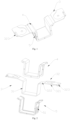
Fig. 1 is a schematic structure view of a battery module busbar provided by an exemplary embodiment of the present disclosure; -
Fig. 2 is a schematic exploded view of a battery module busbar provided by the exemplary embodiment of the present disclosure; and -
Fig. 3 is a schematic partial view of a battery module provided by the exemplary embodiment of the present disclosure. -
- 1: end plate; 2: water conduits;
- 3: busbar body; 31: U-shaped segment;
- 32: extension segments; 321: horizontal segments;
- 322: transition segments; 323: recesses;
- 4: upper casing; 5: lower casing;
- 51: ribs.
- Specific embodiments of the present disclosure will be described in details below in conjunction with the accompanying drawings. It should be understood that the specific embodiments described herein are provided for illustrating and explaining the present disclosure only and are not intended to limit its scope.
- The directional terms used herein such as "upper", "lower", "front" and "back" are with respect to the actual installation status of corresponding components unless stated to the contrary. The terms "inside" and "outside" indicate the inside and outside of the contours of the corresponding components. Same reference numerals in different drawings indicate same or similar elements when the following description is related to the drawings, unless stated otherwise.
- With reference to
Figs. 1 to 3 , the present disclosure provides a battery module busbar. As shown inFig. 3 , the battery module has a U-shaped end plate 1, above a bottom wall of which water conduits 2 or other non-conductive metallic parts are arranged. The battery module busbar comprises anupper casing 4, abusbar body 3 and a lower casing 5 which are arranged successively from top to bottom, wherein thebusbar body 3 comprises aU-shaped segment 31 opening towards the water conduits 2 andextension segments 32 formed by bending outside from side plate faces of theU-shaped segment 31, saidextension segments 32 are used for connecting with cell poles. Theupper casing 4 and the lower casings 5 are each configured into a U-shape so as to fit with theU-shaped segment 31 of thebusbar body 3. A gap is provided between theupper casing 4 and the water conduits 2, and side plate faces of the lower casing 5 are fitted with side walls of the end plate 1. - With the above technical solution, an electrical insulation effect is achieved by the
upper casing 4 and the lower casing 5 enclose therebetween thebusbar body 3 for connecting with cell poles, and use of the space between the end plate 1 and the water conduits 2 can be maximized thanks to the design of the shape of the busbar in which the side plate faces of the lower casing 5 are fitted with the side walls of the end plate 1, so as to ensure that no relative movement and thus no wear will be occurred between the busbar and the end plate 1 during vibration, and friction is also avoided by the certain gap between theupper casing 4 and the water conduits 2. The above arrangement is able to achieve electrical insulated isolation of the busbar between modules inside a limited arrangement space. - According to an embodiment of the present disclosure, as shown in
Fig. 2 , theextension segments 32 may comprise ahorizontal segment 321 and atransition segment 322 which connects thehorizontal segment 321 and theU-shaped segment 31, wherein thetransition segment 322 may have an inclined arrangement and the cell poles may be connected to thehorizontal segment 321 by means of laser welding process. - In an embodiment of the present disclosure, as shown in
Fig. 1 , side walls of theupper casing 4 and the lower casing 5 are bending outside to form bending segments which fit with thetransition segments 322 and arranging above side walls of the end plate 1 such that an insulation protection of thetransition segments 322 can be achieved by means of the bending segments. - With reference to
Fig. 1 , theupper casing 4 and the lower casing 5 are fixedly connected by snap-fit so as to enclose theU-shaped segment 31 therebetween. Specifically, as shown inFig. 2 , one of theupper casing 4 and the lower casing 5 is provided with a plurality of spaced apart slots on both of its front and back ends, and front and back ends of the other are provided with a plurality of projections mating with the respectively slots. - Optionally, with reference to
Figs. 1 and 2 , an end portion of each of theextension segments 32 which is far away from the U-shapedsegment 31 has arecess 323 formed thereon for placing a nickel sheet in therecess 323, so as to conduct voltage temperature sampling. The nickel sheet may be welded inside therecess 323 such that it does not interfere with an upper cover of the battery module and save space. Specifically, a depth of therecess 323 is optionally 0.3mm. - According to some examples and with reference to
Fig. 2 , it is provided on outer walls of the side plate faces of the lower casing 5 along a length direction of each of the side plate faces a plurality of spaced apartribs 51 which extend along their height directions, and saidribs 51 each has a cross section which tapering from top to bottom to guide the mounting of the busbar so as to facilitate the assembly of the busbar on the battery module, as well as making the connection of the lower casing 5 and the end plate 1 more tight. - Specifically, the
upper casing 4 and the lower casing 5 may both made of a material of polylaurylamide which has good insulating property, wear resistance and toughness, and the material of thebusbar body 3 may be aluminum. Note that the materials ofbusbar body 3,upper casing 4 and lower casing 5 may be arbitrarily selected as required and all of them are within the scope of the present disclosure. - Optionally, a distance between the
upper casing 4 and the water conduits 2 is 3 to 5mm, and which in the embodiment of the present disclosure is 4.6mm. - According to a second aspect of the present disclosure, a battery module is also provided which comprises an end plate 1 and a busbar arranged on the end plate 1 for connecting with cell poles. Said busbar is the battery module busbar provided by the present disclosure, which has the same advantages as the above mentioned battery module busbar relative to the prior arts, so details thereof are not repeated hereafter.
- According to a third aspect of the present disclosure, it is further provided a battery pack which comprises the battery module provided by the present disclosure. The battery pack has the same advantages as the above mentioned battery module busbar and the battery module relative to the prior arts, so details thereof are not repeated hereafter.
- The optional embodiments are described above in conjunction with the accompanying drawings, but the present disclosure is not limited by the specific details thereof. Several simple modifications may be made to the technical solution of the present disclosure within its concept, and such modifications are considered within the scope of the present disclosure.
- It should also be noted that respectively specific technical features described in the above specific embodiments may be combined in any suitable manner without conflict. In order to avoid unnecessary repetition, various possible combinations will not be described further.
- Moreover, any combination of various embodiments of the present disclosure may be carried out without departing from its spirit, and such combination should also be considered within the scope of the present disclosure.
Claims (10)
- A battery module busbar comprising a U-shaped end plate (1) above a bottom wall of which water conduits (2) are arranged, characterized in that the battery module busbar comprises an upper casing (4), a busbar body (3) and a lower casing (5) which are arranged successively from top to bottom, wherein the busbar body (3) comprises a U-shaped segment (31) opening towards the water conduits (2) and extension segments (32) formed by bending outside from side plate faces of the U-shaped segment (31), said extension segments (32) are used for connecting with cell poles, the upper casing (4) and the lower casing (5) are both configured into a U-shape so as to fit respectively with the U-shaped segment (31) of the busbar body (3), a gap is provided between the upper casing (4) and the water conduits (2), and side plate faces of the lower casing (5) are fitted with side walls of the end plate (1).
- The method according to claim 1, characterized in that the extension segments (32) each comprises a horizontal segment (321) and a transition segment (322) which connects the horizontal segment (321) and the U-shaped segment (31), and the cell poles are welded to the horizontal segment (321).
- The method according to claim 2, characterized in that side walls of the upper casing (4) and the lower casing (5) are bending outside to form bending segments which fit with the transition segments (322).
- The method according to claim 1, characterized in that the upper casing (4) and the lower casing (5) are fixedly connected by snap-fit so as to enclose the U-shaped segment (31) therebetween.
- The method according to claim 1, characterized in that an end portion of each of the extension segments (32) which is far away from the U-shaped segment (31) has a recess (323) formed thereon for placing a nickel sheet.
- The method according to claim 1, characterized in that it is provided on outer walls of the side plate faces of the lower casing (5) along a length direction of each of the side plate faces a plurality of spaced apart ribs (51) which extend along their height directions, said ribs (51) each has a cross section which tapering from top to bottom.
- The method according to claim 1, characterized in that the upper casing (4) and the lower casing (5) are both made of a material of polylaurylamide, and the busbar body (3) is made of a material of aluminum.
- The method according to claim 1, characterized in that a distance between the upper casing (4) and the water conduits (2) is 3 to 5mm.
- A battery module characterized by comprising an end plate (1) and a busbar arranged on the end plate (1) for connecting with cell poles, wherein said busbar is the battery module busbar according to any one of the claims 1 to 8.
- A battery pack characterized by comprising the battery module according to claim 9.
Applications Claiming Priority (2)
| Application Number | Priority Date | Filing Date | Title |
|---|---|---|---|
| CN202121774812.3U CN215299457U (en) | 2021-07-30 | 2021-07-30 | Battery module busbars, battery modules and battery packs |
| PCT/CN2022/108016 WO2023005938A1 (en) | 2021-07-30 | 2022-07-26 | Battery module busbar, battery module and battery pack |
Publications (2)
| Publication Number | Publication Date |
|---|---|
| EP4379944A1 true EP4379944A1 (en) | 2024-06-05 |
| EP4379944A4 EP4379944A4 (en) | 2024-12-18 |
Family
ID=79525776
Family Applications (1)
| Application Number | Title | Priority Date | Filing Date |
|---|---|---|---|
| EP22848543.9A Pending EP4379944A4 (en) | 2021-07-30 | 2022-07-26 | BATTERY MODULE BUS BAR, BATTERY MODULE AND BATTERY PACK |
Country Status (3)
| Country | Link |
|---|---|
| EP (1) | EP4379944A4 (en) |
| CN (1) | CN215299457U (en) |
| WO (1) | WO2023005938A1 (en) |
Families Citing this family (6)
| Publication number | Priority date | Publication date | Assignee | Title |
|---|---|---|---|---|
| CN215299457U (en) * | 2021-07-30 | 2021-12-24 | 蜂巢能源科技有限公司 | Battery module busbars, battery modules and battery packs |
| CN115498368B (en) * | 2022-09-20 | 2023-07-07 | 天津市捷威动力工业有限公司 | Battery cell connection structure, connection method thereof, battery cell unit and battery module |
| WO2024174834A1 (en) * | 2023-02-21 | 2024-08-29 | 江苏正力新能电池技术有限公司 | Battery pack |
| CN116598692A (en) * | 2023-05-09 | 2023-08-15 | 惠州亿纬锂能股份有限公司 | Battery modules and battery packs |
| CN119253153A (en) * | 2024-09-30 | 2025-01-03 | 厦门新能安科技有限公司 | Battery modules and electrical equipment |
| WO2026095463A1 (en) * | 2024-10-28 | 2026-05-07 | 주식회사 엘지에너지솔루션 | Busbar and battery pack including same |
Family Cites Families (8)
| Publication number | Priority date | Publication date | Assignee | Title |
|---|---|---|---|---|
| JP5054905B2 (en) * | 2005-09-05 | 2012-10-24 | 株式会社オートネットワーク技術研究所 | Connecting the battery output terminal to the terminal fitting |
| JP2007207523A (en) * | 2006-01-31 | 2007-08-16 | Sanyo Electric Co Ltd | Assembled battery |
| JP2014186803A (en) * | 2013-03-22 | 2014-10-02 | Toshiba Corp | Bus bar, electronic component and manufacturing method of electronic component |
| JP6790923B2 (en) * | 2017-03-03 | 2020-11-25 | 株式会社オートネットワーク技術研究所 | Connection module |
| CN210200841U (en) * | 2019-09-30 | 2020-03-27 | 蜂巢能源科技有限公司 | Power battery pack with combinable battery module and power automobile chassis assembly thereof |
| JP7063867B2 (en) * | 2019-10-25 | 2022-05-09 | 矢崎総業株式会社 | Busbar protector |
| CN212810395U (en) * | 2020-08-31 | 2021-03-26 | 蜂巢能源科技有限公司 | Battery module, battery package and vehicle |
| CN215299457U (en) * | 2021-07-30 | 2021-12-24 | 蜂巢能源科技有限公司 | Battery module busbars, battery modules and battery packs |
-
2021
- 2021-07-30 CN CN202121774812.3U patent/CN215299457U/en active Active
-
2022
- 2022-07-26 WO PCT/CN2022/108016 patent/WO2023005938A1/en not_active Ceased
- 2022-07-26 EP EP22848543.9A patent/EP4379944A4/en active Pending
Also Published As
| Publication number | Publication date |
|---|---|
| EP4379944A4 (en) | 2024-12-18 |
| WO2023005938A1 (en) | 2023-02-02 |
| CN215299457U (en) | 2021-12-24 |
Similar Documents
| Publication | Publication Date | Title |
|---|---|---|
| EP3770995A1 (en) | Single-cell battery, battery module, power battery and electric vehicle | |
| CN215299457U (en) | Battery module busbars, battery modules and battery packs | |
| EP2757611B1 (en) | Battery module | |
| EP3166158B1 (en) | Rechargeable battery module | |
| JP6593997B2 (en) | Busbar module | |
| CN102714381B (en) | Conduction path connection structure | |
| JP6500771B2 (en) | connector | |
| EP2808927A1 (en) | Battery module | |
| US10950915B2 (en) | Connection module including bus bar extending over groove accomodating connection module-side wires | |
| JP6018542B2 (en) | Busbar structure | |
| EP3905363B1 (en) | Battery module | |
| EP3748712A1 (en) | Battery power extraction and integration structure, battery pack and vehicle | |
| JP2017098043A (en) | Holding structure for terminal for voltage detection | |
| EP4354644A1 (en) | Cell module assembly and battery pack comprising same | |
| JP2010061962A (en) | Terminal structure of secondary battery, secondary battery, and secondary battery module | |
| US9912082B2 (en) | Electric wire connection structure | |
| JP2021069220A (en) | Bus bar protector | |
| CN106100569B (en) | Terminal box and solar battery module | |
| CN220086196U (en) | Shell, battery and battery pack | |
| CN113991343B (en) | A power supply structure | |
| CN110492278A (en) | Busbar connector and battery modules, battery system and electric vehicle with the busbar connector | |
| CN219739192U (en) | Battery module | |
| WO2023165376A1 (en) | Sampling assembly, battery, and electric device | |
| CN219717182U (en) | Busbar protector and battery pack | |
| JP6351395B2 (en) | Busbar module |
Legal Events
| Date | Code | Title | Description |
|---|---|---|---|
| STAA | Information on the status of an ep patent application or granted ep patent |
Free format text: STATUS: THE INTERNATIONAL PUBLICATION HAS BEEN MADE |
|
| PUAI | Public reference made under article 153(3) epc to a published international application that has entered the european phase |
Free format text: ORIGINAL CODE: 0009012 |
|
| STAA | Information on the status of an ep patent application or granted ep patent |
Free format text: STATUS: REQUEST FOR EXAMINATION WAS MADE |
|
| 17P | Request for examination filed |
Effective date: 20240226 |
|
| AK | Designated contracting states |
Kind code of ref document: A1 Designated state(s): AL AT BE BG CH CY CZ DE DK EE ES FI FR GB GR HR HU IE IS IT LI LT LU LV MC MK MT NL NO PL PT RO RS SE SI SK SM TR |
|
| DAV | Request for validation of the european patent (deleted) | ||
| DAX | Request for extension of the european patent (deleted) | ||
| A4 | Supplementary search report drawn up and despatched |
Effective date: 20241114 |
|
| RIC1 | Information provided on ipc code assigned before grant |
Ipc: H01M 50/526 20210101ALI20241108BHEP Ipc: H01M 50/516 20210101ALI20241108BHEP Ipc: H01M 50/505 20210101ALI20241108BHEP Ipc: H01M 10/6567 20140101ALI20241108BHEP Ipc: H01M 10/6557 20140101ALI20241108BHEP Ipc: H01M 10/613 20140101ALI20241108BHEP Ipc: H01M 50/593 20210101ALI20241108BHEP Ipc: H01M 50/588 20210101ALI20241108BHEP Ipc: H01M 50/507 20210101ALI20241108BHEP Ipc: H01M 50/503 20210101AFI20241108BHEP |
|
| RIN1 | Information on inventor provided before grant (corrected) |
Inventor name: LI, ZHENGZHE Inventor name: ZHANG, QIAORAN Inventor name: GE, YOUWEI |