EP4379929A1 - Battery cell unit, battery, and vehicle - Google Patents
Battery cell unit, battery, and vehicle Download PDFInfo
- Publication number
- EP4379929A1 EP4379929A1 EP22897842.5A EP22897842A EP4379929A1 EP 4379929 A1 EP4379929 A1 EP 4379929A1 EP 22897842 A EP22897842 A EP 22897842A EP 4379929 A1 EP4379929 A1 EP 4379929A1
- Authority
- EP
- European Patent Office
- Prior art keywords
- battery core
- conductive sheet
- battery
- supporting
- core unit
- Prior art date
- Legal status (The legal status is an assumption and is not a legal conclusion. Google has not performed a legal analysis and makes no representation as to the accuracy of the status listed.)
- Pending
Links
- 239000012790 adhesive layer Substances 0.000 claims description 15
- 229910052782 aluminium Inorganic materials 0.000 claims description 11
- XAGFODPZIPBFFR-UHFFFAOYSA-N aluminium Chemical compound [Al] XAGFODPZIPBFFR-UHFFFAOYSA-N 0.000 claims description 11
- 238000005192 partition Methods 0.000 claims description 7
- 238000003466 welding Methods 0.000 claims description 5
- 238000010586 diagram Methods 0.000 description 6
- 238000000034 method Methods 0.000 description 3
- 230000009466 transformation Effects 0.000 description 2
- 238000000844 transformation Methods 0.000 description 2
- 239000004831 Hot glue Substances 0.000 description 1
- 229910000831 Steel Inorganic materials 0.000 description 1
- 238000005452 bending Methods 0.000 description 1
- 238000001816 cooling Methods 0.000 description 1
- 230000000694 effects Effects 0.000 description 1
- 230000017525 heat dissipation Effects 0.000 description 1
- 239000000463 material Substances 0.000 description 1
- 229910052751 metal Inorganic materials 0.000 description 1
- 239000002184 metal Substances 0.000 description 1
- 230000035939 shock Effects 0.000 description 1
- 239000010959 steel Substances 0.000 description 1
Images



Classifications
-
- H—ELECTRICITY
- H01—ELECTRIC ELEMENTS
- H01M—PROCESSES OR MEANS, e.g. BATTERIES, FOR THE DIRECT CONVERSION OF CHEMICAL ENERGY INTO ELECTRICAL ENERGY
- H01M50/00—Constructional details or processes of manufacture of the non-active parts of electrochemical cells other than fuel cells, e.g. hybrid cells
- H01M50/20—Mountings; Secondary casings or frames; Racks, modules or packs; Suspension devices; Shock absorbers; Transport or carrying devices; Holders
- H01M50/258—Modular batteries; Casings provided with means for assembling
-
- H—ELECTRICITY
- H01—ELECTRIC ELEMENTS
- H01M—PROCESSES OR MEANS, e.g. BATTERIES, FOR THE DIRECT CONVERSION OF CHEMICAL ENERGY INTO ELECTRICAL ENERGY
- H01M50/00—Constructional details or processes of manufacture of the non-active parts of electrochemical cells other than fuel cells, e.g. hybrid cells
- H01M50/20—Mountings; Secondary casings or frames; Racks, modules or packs; Suspension devices; Shock absorbers; Transport or carrying devices; Holders
- H01M50/204—Racks, modules or packs for multiple batteries or multiple cells
-
- H—ELECTRICITY
- H01—ELECTRIC ELEMENTS
- H01M—PROCESSES OR MEANS, e.g. BATTERIES, FOR THE DIRECT CONVERSION OF CHEMICAL ENERGY INTO ELECTRICAL ENERGY
- H01M50/00—Constructional details or processes of manufacture of the non-active parts of electrochemical cells other than fuel cells, e.g. hybrid cells
- H01M50/20—Mountings; Secondary casings or frames; Racks, modules or packs; Suspension devices; Shock absorbers; Transport or carrying devices; Holders
- H01M50/204—Racks, modules or packs for multiple batteries or multiple cells
- H01M50/207—Racks, modules or packs for multiple batteries or multiple cells characterised by their shape
- H01M50/209—Racks, modules or packs for multiple batteries or multiple cells characterised by their shape adapted for prismatic or rectangular cells
-
- H—ELECTRICITY
- H01—ELECTRIC ELEMENTS
- H01M—PROCESSES OR MEANS, e.g. BATTERIES, FOR THE DIRECT CONVERSION OF CHEMICAL ENERGY INTO ELECTRICAL ENERGY
- H01M50/00—Constructional details or processes of manufacture of the non-active parts of electrochemical cells other than fuel cells, e.g. hybrid cells
- H01M50/20—Mountings; Secondary casings or frames; Racks, modules or packs; Suspension devices; Shock absorbers; Transport or carrying devices; Holders
- H01M50/204—Racks, modules or packs for multiple batteries or multiple cells
- H01M50/207—Racks, modules or packs for multiple batteries or multiple cells characterised by their shape
- H01M50/211—Racks, modules or packs for multiple batteries or multiple cells characterised by their shape adapted for pouch cells
-
- H—ELECTRICITY
- H01—ELECTRIC ELEMENTS
- H01M—PROCESSES OR MEANS, e.g. BATTERIES, FOR THE DIRECT CONVERSION OF CHEMICAL ENERGY INTO ELECTRICAL ENERGY
- H01M50/00—Constructional details or processes of manufacture of the non-active parts of electrochemical cells other than fuel cells, e.g. hybrid cells
- H01M50/20—Mountings; Secondary casings or frames; Racks, modules or packs; Suspension devices; Shock absorbers; Transport or carrying devices; Holders
- H01M50/244—Secondary casings; Racks; Suspension devices; Carrying devices; Holders characterised by their mounting method
-
- H—ELECTRICITY
- H01—ELECTRIC ELEMENTS
- H01M—PROCESSES OR MEANS, e.g. BATTERIES, FOR THE DIRECT CONVERSION OF CHEMICAL ENERGY INTO ELECTRICAL ENERGY
- H01M50/00—Constructional details or processes of manufacture of the non-active parts of electrochemical cells other than fuel cells, e.g. hybrid cells
- H01M50/20—Mountings; Secondary casings or frames; Racks, modules or packs; Suspension devices; Shock absorbers; Transport or carrying devices; Holders
- H01M50/249—Mountings; Secondary casings or frames; Racks, modules or packs; Suspension devices; Shock absorbers; Transport or carrying devices; Holders specially adapted for aircraft or vehicles, e.g. cars or trains
-
- H—ELECTRICITY
- H01—ELECTRIC ELEMENTS
- H01M—PROCESSES OR MEANS, e.g. BATTERIES, FOR THE DIRECT CONVERSION OF CHEMICAL ENERGY INTO ELECTRICAL ENERGY
- H01M50/00—Constructional details or processes of manufacture of the non-active parts of electrochemical cells other than fuel cells, e.g. hybrid cells
- H01M50/20—Mountings; Secondary casings or frames; Racks, modules or packs; Suspension devices; Shock absorbers; Transport or carrying devices; Holders
- H01M50/262—Mountings; Secondary casings or frames; Racks, modules or packs; Suspension devices; Shock absorbers; Transport or carrying devices; Holders with fastening means, e.g. locks
- H01M50/264—Mountings; Secondary casings or frames; Racks, modules or packs; Suspension devices; Shock absorbers; Transport or carrying devices; Holders with fastening means, e.g. locks for cells or batteries, e.g. straps, tie rods or peripheral frames
-
- H—ELECTRICITY
- H01—ELECTRIC ELEMENTS
- H01M—PROCESSES OR MEANS, e.g. BATTERIES, FOR THE DIRECT CONVERSION OF CHEMICAL ENERGY INTO ELECTRICAL ENERGY
- H01M50/00—Constructional details or processes of manufacture of the non-active parts of electrochemical cells other than fuel cells, e.g. hybrid cells
- H01M50/50—Current conducting connections for cells or batteries
-
- H—ELECTRICITY
- H01—ELECTRIC ELEMENTS
- H01M—PROCESSES OR MEANS, e.g. BATTERIES, FOR THE DIRECT CONVERSION OF CHEMICAL ENERGY INTO ELECTRICAL ENERGY
- H01M50/00—Constructional details or processes of manufacture of the non-active parts of electrochemical cells other than fuel cells, e.g. hybrid cells
- H01M50/50—Current conducting connections for cells or batteries
- H01M50/502—Interconnectors for connecting terminals of adjacent batteries; Interconnectors for connecting cells outside a battery casing
- H01M50/503—Interconnectors for connecting terminals of adjacent batteries; Interconnectors for connecting cells outside a battery casing characterised by the shape of the interconnectors
-
- H—ELECTRICITY
- H01—ELECTRIC ELEMENTS
- H01M—PROCESSES OR MEANS, e.g. BATTERIES, FOR THE DIRECT CONVERSION OF CHEMICAL ENERGY INTO ELECTRICAL ENERGY
- H01M50/00—Constructional details or processes of manufacture of the non-active parts of electrochemical cells other than fuel cells, e.g. hybrid cells
- H01M50/50—Current conducting connections for cells or batteries
- H01M50/502—Interconnectors for connecting terminals of adjacent batteries; Interconnectors for connecting cells outside a battery casing
- H01M50/509—Interconnectors for connecting terminals of adjacent batteries; Interconnectors for connecting cells outside a battery casing characterised by the type of connection, e.g. mixed connections
- H01M50/51—Connection only in series
-
- H—ELECTRICITY
- H01—ELECTRIC ELEMENTS
- H01M—PROCESSES OR MEANS, e.g. BATTERIES, FOR THE DIRECT CONVERSION OF CHEMICAL ENERGY INTO ELECTRICAL ENERGY
- H01M50/00—Constructional details or processes of manufacture of the non-active parts of electrochemical cells other than fuel cells, e.g. hybrid cells
- H01M50/50—Current conducting connections for cells or batteries
- H01M50/531—Electrode connections inside a battery casing
- H01M50/533—Electrode connections inside a battery casing characterised by the shape of the leads or tabs
-
- H—ELECTRICITY
- H01—ELECTRIC ELEMENTS
- H01M—PROCESSES OR MEANS, e.g. BATTERIES, FOR THE DIRECT CONVERSION OF CHEMICAL ENERGY INTO ELECTRICAL ENERGY
- H01M50/00—Constructional details or processes of manufacture of the non-active parts of electrochemical cells other than fuel cells, e.g. hybrid cells
- H01M50/50—Current conducting connections for cells or batteries
- H01M50/531—Electrode connections inside a battery casing
- H01M50/536—Electrode connections inside a battery casing characterised by the method of fixing the leads to the electrodes, e.g. by welding
-
- H—ELECTRICITY
- H01—ELECTRIC ELEMENTS
- H01M—PROCESSES OR MEANS, e.g. BATTERIES, FOR THE DIRECT CONVERSION OF CHEMICAL ENERGY INTO ELECTRICAL ENERGY
- H01M2220/00—Batteries for particular applications
- H01M2220/20—Batteries in motive systems, e.g. vehicle, ship, plane
-
- Y—GENERAL TAGGING OF NEW TECHNOLOGICAL DEVELOPMENTS; GENERAL TAGGING OF CROSS-SECTIONAL TECHNOLOGIES SPANNING OVER SEVERAL SECTIONS OF THE IPC; TECHNICAL SUBJECTS COVERED BY FORMER USPC CROSS-REFERENCE ART COLLECTIONS [XRACs] AND DIGESTS
- Y02—TECHNOLOGIES OR APPLICATIONS FOR MITIGATION OR ADAPTATION AGAINST CLIMATE CHANGE
- Y02E—REDUCTION OF GREENHOUSE GAS [GHG] EMISSIONS, RELATED TO ENERGY GENERATION, TRANSMISSION OR DISTRIBUTION
- Y02E60/00—Enabling technologies; Technologies with a potential or indirect contribution to GHG emissions mitigation
- Y02E60/10—Energy storage using batteries
-
- Y—GENERAL TAGGING OF NEW TECHNOLOGICAL DEVELOPMENTS; GENERAL TAGGING OF CROSS-SECTIONAL TECHNOLOGIES SPANNING OVER SEVERAL SECTIONS OF THE IPC; TECHNICAL SUBJECTS COVERED BY FORMER USPC CROSS-REFERENCE ART COLLECTIONS [XRACs] AND DIGESTS
- Y02—TECHNOLOGIES OR APPLICATIONS FOR MITIGATION OR ADAPTATION AGAINST CLIMATE CHANGE
- Y02E—REDUCTION OF GREENHOUSE GAS [GHG] EMISSIONS, RELATED TO ENERGY GENERATION, TRANSMISSION OR DISTRIBUTION
- Y02E60/00—Enabling technologies; Technologies with a potential or indirect contribution to GHG emissions mitigation
- Y02E60/30—Hydrogen technology
- Y02E60/50—Fuel cells
Definitions
- the present disclosure relates to the technical field of batteries, and more specifically, to a battery core unit and a battery.
- a conventional pouch battery is assembled from multiple battery core units stacked and fixed in a single dimension. This single-dimensional stacking connection is not conducive to improvement of the overall battery capacity.
- battery cores of the conventional pouch battery are connected by connection sheets and then fastened by bolts to realize the connection between the battery cores. The assembly process is complicated and inefficient.
- the battery cores need to be bound by steel belts after being stacked, leading to a large number of parts and high costs.
- the content of the present disclosure is intended to resolve at least one of the technical problems existing in related arts.
- an embodiment of the present disclosure discloses a battery core unit, including:
- the multiple battery core modules are connected in series.
- the battery core module includes at least one battery core group and brackets arranged at two ends of the at least one battery core group.
- Each battery core group includes multiple battery cores stacked along a first direction, and the multiple battery cores are connected in parallel.
- the first direction being a thickness direction of the battery core.
- the bracket includes a bracket body and a conductive sheet mounted on the bracket body. At least one tab protruding hole is provided on the bracket body, and a tab of the battery core extends through the tab protruding hole and is connected to the conductive sheet.
- the battery core module further includes a supporting and fastening piece, and the supporting and fastening piece is arranged between the brackets at the two ends of the at least one battery core group.
- the conductive sheet includes a first conductive sheet and a second conductive sheet.
- the first conductive sheet and the second conductive sheet are mutually connected and arranged at an angle.
- a tab avoiding hole is provided between the first conductive sheet and the second conductive sheet.
- the tab of the battery core extends through the tab protruding hole and the tab avoiding hole in sequence and is connected to the first conductive sheet.
- the bracket body has a first side surface, a second side surface, and a third side surface.
- the first side surface is a surface close to the battery core
- the second side surface is a surface opposite to the first side surface and facing away from the battery core
- the third side surface is a surface parallel to a lead-out direction of the tab of the battery core and perpendicular to the first direction.
- the first conductive sheet is arranged on the second side surface.
- the second conductive sheet is arranged on the third side surface.
- supporting and limiting grooves are provided on the bracket body, and the supporting and fastening piece is inserted into the supporting and limiting grooves.
- the supporting and limiting groove are V-shaped grooves.
- the supporting and fastening piece is an aluminum plate.
- the battery core unit further includes an intermediate connection sheet respectively connected to second conductive sheets on brackets of adjacent battery core modules, where the adjacent battery core modules are connected in series by the intermediate connection sheet.
- the supporting and fastening piece and the battery core group are stacked and arranged along the first direction.
- An adhesive layer is arranged on the supporting and fastening piece, and the supporting and fastening piece is adhered to the battery core group by the adhesive layer.
- the bracket body is connected to the conductive sheet by a clamping structure.
- the at least one battery core group is one battery core group
- the brackets are arranged at the two ends of the battery core group, and each bracket is provided with one conductive sheet.
- a conductive sheet of a first polarity of one battery core module is connected to a conductive sheet of a second polarity of an adjacent battery core module by the intermediate connection sheet.
- the at least one battery core group is multiple battery core groups, the multiple battery core groups are arranged along the first direction, and the brackets are arranged at the two ends of the multiple battery core groups.
- Each bracket is provided with multiple conductive sheets.
- a number of the conductive sheets is the same as a number of the multiple battery core groups.
- Adjacent conductive sheets arranged along the first direction have opposite polarities.
- the battery core unit further includes intermediate connection sheet.
- a conductive sheet of one battery core module is connected to a conductive sheet of an adjacent battery core module by the intermediate connection sheet.
- the battery core unit further includes a tail connection sheet, and the tail connection sheet is mounted on a bracket of a battery core module that serves as an end portion of the battery core unit.
- the tail connection sheet is integrally formed with the multiple conductive sheets on the bracket.
- an insulating partition portion is arranged on the bracket body, and the insulating partition portion is arranged between conductive sheets connected to different battery core groups.
- the tab extends through the tab protruding hole and is bent to form a bent portion, and the bent portion is connected to the conductive sheet by welding.
- elastic clamping buttons are provided on the bracket body, the conductive sheet is provided with clamping holes corresponding to the elastic clamping buttons, and the conductive sheets are mounted on the bracket body by the clamping holes and the elastic clamping buttons.
- the battery core unit disclosed in this embodiment of the present disclosure is formed by connecting battery core modules in series, and the battery core module is composed of at least one battery core group and assembled and fastened by brackets.
- the battery core modules connected in series may be arranged based on an actual requirement.
- the battery core groups are assembled into the battery core module, to become a standardized battery core module, and standardized battery core modules may be further arbitrarily connected, based on actual requirement, in series to form battery core units with different sizes, and then form batteries with different sizes.
- the battery core unit in this embodiment of the present disclosure is simple to install, has high grouping efficiency, and has extremely high space utilization rate in a battery case that can be as high as 98%.
- the battery core modules constituting the battery core unit are highly replicable. This is convenient to form battery packs with different arrangements and standards.
- An embodiment of the present disclosure further discloses a battery, including a housing.
- the battery further includes the battery core unit described in the embodiment of the present disclosure, and the battery core unit is accommodated in the housing.
- An embodiment of the present disclosure further discloses a vehicle.
- the vehicle includes the battery core unit described in the embodiment of the present disclosure and a chassis structure configured for accommodating the battery core unit.
- a battery core unit 1 of the present disclosure includes multiple battery core modules 10 connected in series, and the battery core module 10 includes at least one battery core group 11 and brackets 12 arranged at two ends of the battery core group 11.
- the battery core group 11 includes multiple battery cores 111 stacked along a first direction, the battery core 111 have tabs 112, and the first direction is a thickness direction of the battery cores 111.
- the multiple battery cores 111 in the battery core group 11 are connected in parallel.
- An end portion of the battery core group 11 is an end portion of the battery core group 11 along a second direction, and the second direction is a lead-out direction of the tabs 112 of the battery core 111.
- a bracket 12 includes a bracket body 121 and conductive sheets 122 mounted on the bracket body 121.
- the multiple battery cores 111 of the battery core group 11 are connected in parallel and connected to the conductive sheets 122 on the bracket 12, and conductive sheets 122 on brackets 12 of adjacent two battery core modules 10 are connected. This implements a series connection between the adjacent two battery core modules 10.
- tab protruding holes 1211 are provided on the bracket body 121, the tab protruding holes 1211 are provided corresponding to tabs 112 of the battery cores 111, and a number of the tab protruding holes 1211 is the same as a number of the battery cores 111 of the battery core group 11.
- the tabs 112 of the multiple battery cores 111 in the battery core group 11 extend through the corresponding tab protruding holes 1211 and are connected to the conductive sheets 122.
- the tabs 112 and the conductive sheets 122 may be connected by welding or another connection method.
- the tabs 112 extend through the corresponding tab protruding holes 1211 and are bent to form bent portions, and bent portions are welded with the conductive sheets 122.
- the number of tab protruding holes 1211 may be the same as a number of the battery core group 11. Tabs of the multiple battery cores 111 in the battery core group 11 are first welded together to form a converged tab, to be connected in parallel, and then extend through the tab protruding hole 1211 to be connected to the conductive sheets 122.
- a battery core module 10 further includes a supporting and fastening piece 15, and the supporting and fastening piece 15 is arranged between the brackets 12 at the two ends of the battery core group 11 to support and fasten the brackets 12.
- supporting and limiting grooves 1212 are provided on the bracket body 12, and the supporting and fastening piece 15 is inserted into the supporting and limiting grooves 1212 to support and fasten the brackets 12 at the two ends of the battery core group 11, so that the battery core group 11 and the brackets 12 form a battery core module 10 with a stable structure.
- the supporting and fastening piece 15 is an aluminum plate, and the supporting and limiting grooves 1212 are V-shaped grooves.
- the V-shaped groove is designed to facilitate clamping and fastening of the supporting and fastening piece 15.
- the supporting and fastening piece 15 and a stacking surface of the battery core 111 have a same shape and size.
- the stacking surface of the battery core 111 is perpendicular to the first direction.
- the supporting and fastening piece 15 can also avoid shock and vibration of the tabs 112 of the battery core 111 in a direction in which the tabs 112 are led out.
- the supporting and fastening piece 15 limits locations of the brackets 12 at the two ends of the battery core group 11, and prevents the brackets 12 from moving and causing damage to the tabs 112.
- An adhesive layer is arranged on the supporting and fastening piece 15, and the supporting and fastening piece 15 is adhered to the battery core group 11 by the adhesive layer.
- a supporting and fastening piece 15 may be arranged between adjacent two battery core groups 11, adhesive layers may be arranged on both sides of the supporting and fastening piece 15, and the supporting and fastening piece 15 is adhered to the adjacent battery core groups 11 by the adhesive layers.
- the adhesive layer is preferably hot melt adhesive, and it can be understood that a material selection of the adhesive layer is not limited to this.
- the adhesive layer may be provided based on an actual requirement, for example, may be provided only on one side of the supporting and fastening piece 15, or a partial area or an entire area of one side of the supporting and fastening piece 15, or a partial area or an entire area of both sides of the supporting and fastening piece 15.
- the supporting and fastening piece 15 implements supporting and fastening, and can transfer heat of the battery core group 11 adhered to the supporting and fastening piece 15 to an external aluminum housing, and the aluminum housing further transfers the heat to a cooling apparatus to keep a battery temperature in a suitable range.
- the conductive sheet 122 includes a first conductive sheet 1221 and a second conductive sheet 1222 connected to the first conductive sheet 1221.
- the first conductive sheet 1221 and the second conductive sheet 1222 are mutually connected and arranged at an angle. It may be understood that the first conductive sheet 1221 and the second conductive sheet 1222 may be connected by a conventional means such as welding or may be integrally formed.
- a tab avoiding hole 1223 is provided between the first conductive sheet 1221 and the second conductive sheet 1222.
- the tab avoiding hole 1223 is provided corresponding to the tab protruding hole 1211.
- the tab avoiding hole 1223 is provided at a junction of the first conductive sheet 1221 and the second conductive sheet 1222.
- the tab avoiding hole 1223 is provided at a bending location of the first conductive sheet 1221 and the second conductive sheet 1222.
- the first conductive sheet 1221 is arranged perpendicularly to the second conductive sheet 1222.
- the first conductive sheet 1221 and the second conductive sheet 1222 may be arranged at a non-right angle.
- the tab 112 of the battery core 111 extends through the tab protruding hole 1211 and the tab avoiding hole 1223 in sequence and is connected to the first conductive sheet 1221.
- the bracket body 121 has a first side surface 1216, a second side surface 1217 and a third side surface 1218.
- the first side surface 1216 of the bracket body 121 is a surface close to the battery core 111.
- the second side surface 1217 of the bracket body 121 is a surface opposite to the first side surface 1216 and facing away from the battery core 111.
- the third side surface 1218 of the bracket body 121 is a surface parallel to a lead-out direction of the tab 112 of the battery core, and the third side surface 1218 is perpendicular to the first direction.
- the first conductive sheet 1221 is arranged on the second side surface 1217 of the bracket body 121.
- the second conductive sheet 1222 is arranged on the third side surface 1218 of the bracket body 121.
- the supporting and limiting groove 1212 is provided on the first side surface 1216 of the bracket body 121.
- the tab 112 of the battery core 111 of the battery core group 11 extends through the tab protruding hole 1211 and the tab avoiding hole 1223 and is welded to the first conductive sheet 1221.
- the battery core unit 1 further includes an intermediate connection sheet 13, and adjacent two battery core modules 10 are connected by the intermediate connection sheet 13.
- the intermediate connection sheet 13 is connected to second conductive sheets 1222 of the adjacent two battery core modules 10. This forms a series connection between the battery core modules 10.
- the conductive sheets 122 are connected to the bracket body 121 by a clamping mechanism.
- elastic clamping buttons 1213 are provided on the bracket body 121
- the conductive sheet 122 is provided with clamping holes 1224 corresponding to the elastic clamping buttons 1213.
- the clamping holes 1224 of the conductive sheet 122 are pressed forcibly to clamp the clamping holes 1224 to outer sides of the elastic clamping buttons 1213, so that the conductive sheet 122 is mounted on the bracket body 121.
- the clamping holes 1224 are provided on the second conductive sheet 1222.
- a clamping recess 1225 is further provided on the first conductive sheet 1221, and a clamping convex button 1214 corresponding to the clamping recess 1225 is provided on the bracket body 121.
- the clamping recess 1225 of the first conductive sheet 1221 is engaged with the clamping convex button 1214 of the bracket body 121 to further ensure stability of a connection between the conductive sheet 122 and the bracket body 121.
- the multiple battery cores 111 in the battery core group 11 are adhered together by the adhesive layer. This increases rigidity and strength of the entire battery core group 11. Tabs of a same polarity of the battery cores 111 in the battery core group 11 are led out from a same direction, and the tabs of the same polarity of the battery cores 111 in the battery core group 11 are connected to the conductive sheet 122 to form a parallel relationship after being led out from the same direction.
- the battery core 111 has a first polarity and a second polarity.
- the first polarity is a negative electrode
- the second polarity is a positive electrode.
- the first polarity is positive electrode
- the second polarity is a negative electrode.
- the tabs 112 of the battery core 111 are connected to the conductive sheet 122 after being led out, and the conductive sheet 122 also has the same polarity, namely, the first polarity or the second polarity, as the tab 112 of the battery core 111. Therefore, the battery core group 11 composed of the battery core 111 and the battery core module 10 also have the first polarity and the second polarity.
- a conductive sheet 122 of a first polarity of one battery core module 10 is connected to a conductive sheet 122 of a second polarity of another adjacent battery core module 10. This implements a series connection between adjacent two battery core modules 10.
- a conductive sheet 122 of a first polarity of one battery core module 10 is connected to a conductive sheet 122 of a second polarity of another adjacent battery core module 10 by an intermediate connection sheet 13.
- the multiple battery core groups 11 are arranged in the first direction.
- Polarities of adjacent battery core groups 11 are arranged in reverse direction.
- Reverse arrangement means that, for example, a first end of one battery core group 11 has a first polarity, and a second end of the battery core group 11 has a second polarity; and a first end of an adjacent battery core group 11 has a second polarity, and a second end of the adjacent battery core group 11 has a first polarity.
- a supporting and fastening piece 15 is arranged between each battery core group 11.
- a conductive sheet 122 is respectively connected to each of two ends of each battery core groups 11.
- an insulating partition portion 1215 is further arranged on the bracket body 121, and the insulating partition portion 1215 is arranged between conductive sheets 122 connected to different battery core groups 11.
- the battery core unit 1 includes multiple battery core modules 10 connected in series, the battery core module 10 includes one battery core group 11 and brackets 12 arranged at two ends of the battery core group 11, and one conductive sheet 122 is arranged on the bracket 12. Tabs 112 of a same polarity of multiple battery cores 111 in the battery core group 11 extend through a tab protruding hole 1211 of the bracket 12 and a tab avoiding hole 1223 of the conductive sheet 122, and are bent and connected to the conductive sheet 122.
- An intermediate connection sheet 13 is connected to a conductive sheet 122 of one polarity of one battery core group 11, and the intermediate connection sheet 13 is connected to a conductive sheet 122 of the other polarity of an adjacent battery core group 11. Adjacent battery core modules 10 are connected in series by the intermediate connection sheet 13.
- a battery core unit 1 includes multiple battery core modules 10 connected in series, and the battery core module 10 includes multiple battery core groups 11 and brackets 12 arranged at two ends of each of the battery core groups 11.
- the multiple battery core groups 11 are arranged along a first direction.
- a plurality of conductive sheets 122 are arranged on the bracket 12.
- a number of the conductive sheets 122 is the same as a number of the plurality of battery core groups 11.
- Adjacent conductive sheets 122 arranged along the first direction have opposite polarities.
- a conductive sheet 122 of one battery core module 10 is connected to a conductive sheet 122 of another adjacent battery core module 10 by an intermediate connection sheet 13.
- the battery core unit 1 further includes a tail connection sheet 14, and the tail connection sheet 14 is mounted on a bracket 12 of a battery core module 10 that serves as an end portion of the battery core unit 1.
- the tail connection sheet 14 can connect different polarities of the battery core module 10 that serve as the end portion of the battery core unit 1, to implement a series connection of the entire battery core unit.
- the tail connection sheet 14 may be a transverse connection sheet or a straight connection sheet.
- the tail connection sheet 14 is connected to the multiple conductive sheets on the bracket 12. Further, as shown in FIG. 10 and FIG. 11 , the tail connection sheet 14 may be integrally formed with the multiple conductive sheets 122 on the bracket 12. As shown in FIG. 11 , there are two tail connection sheets 14. A specific number of tail connection sheets 14 is not limited to this.
- the battery core module 10 includes two battery core groups 11 and brackets 12 arranged at two ends of the battery core group 11.
- a number of battery core groups 11 is not limited to this, and may be increased based on an actual requirement.
- that the battery core module 10 includes two sets of battery core groups 11 is used as an example for description.
- the battery core module 10 includes a first battery core group 113 and a second battery core group 114, and each of the first battery core group 113 and the second battery core group 114 includes multiple battery cores 111.
- the battery core module 10 also includes brackets 12 that are arranged at two ends of the first battery core group 113 and the second battery core group 114 at the same time and that include a first bracket 123 and a second bracket 124.
- the first bracket 123 and the second bracket 124 have a same structure and are arranged opposite to each other.
- Two conductive sheets 122 are arranged on each of the first bracket 123 and the second bracket 124.
- Tabs 112 of a first polarity of the multiple battery cores 111 in the first battery core group 113 extend through a tab protruding hole 1211 of the first bracket 123 and the tab avoiding hole 1223 of one conductive sheet 122, and are bent and connected to the conductive sheet 122.
- Tabs 112 of a second polarity of the multiple battery cores 111 in the second battery core group 114 extend through a tab protruding hole 1211 of the first bracket 123 and a tab avoiding hole 1223 of the other conductive sheet 122, and are bent and connected to the other conductive sheet 122.
- a specific connection manner between the tabs 112 of the battery cores 111 and the conductive sheet 122 after the tabs 112 are led out may be welding or another connection manner that can implement an electrical connection.
- tabs 112 of a second polarity of the multiple battery cores 111 in the first battery core group 113 extend through a tab protruding hole 1211 of the second bracket 124 and a tab avoiding hole 1223 of one conductive sheet 122, and are bent and connected to the conductive sheet 122.
- Tabs 112 of a first polarity of the multiple battery cores 111 in the second battery core group 114 extend through a tab protruding hole 1211 of the second bracket 124 and a tab avoiding hole 1223 of the other conductive sheet 122, and are bent and connected to the other conductive sheet 122.
- the first bracket 123 and the second bracket 124 are arranged opposite to each other.
- Supporting and limiting grooves 1212 are provided on the first bracket 123 and the second bracket 124, and a supporting and fastening piece 15 is inserted into the supporting and limiting groove 1212 of the first bracket 123 and the supporting and limiting groove 1212 of the second bracket 124 to support and fasten the battery core module 10.
- the supporting and fastening piece 15 is disposed at an intermediate location of the battery core module 10, namely, between the first battery core group 113 and the second battery core group 114.
- the supporting and fastening piece 15 is an aluminum plate, both sides of the aluminum plate are provided with adhesive layers, and the aluminum plate is adhered to the first battery core group 113 and the second battery core group 114 by the adhesive layers.
- the adhesive layer may be provided based on an actual requirement, for example, may be provided only on one side of the aluminum plate, or a partial area or an entire area of one side of the aluminum plate, or a partial area or an entire area of both sides of the aluminum plate.
- the battery core unit 1 further includes a tail connection sheet 14.
- the tail connection sheet 14 is arranged on a second side surface 1217 of a bracket 12 of a battery core module 10 that serves as an end portion of the battery core unit 1.
- the tail connection sheet 14 connects tabs of opposite polarities of battery core groups 11 of the battery core module 10 that serves as the end portion of the battery core unit 1, to implement an overall series connection of multiple battery core modules 10.
- the battery core modules 10 connected in series in the present disclosure may be arranged based on an actual requirement.
- the battery core groups 11 are assembled into the battery core module 10, to become a standardized battery core module 10, and standardized battery core modules may be further arbitrarily connected, based on actual requirement, in series to form battery core units with different sizes, and then form batteries with different sizes.
- the battery core unit of the present disclosure is simple to install, has high grouping efficiency, and has extremely high space utilization rate in a battery case that can be as high as 98%.
- the battery core modules constituting the battery core unit are highly replicable. This is convenient to form battery packs with different arrangements and standards.
- the present disclosure further discloses a battery 3, which includes the battery core unit 1 of any of the foregoing embodiments and a housing 2 configured for accommodating the battery core unit 1.
- the present disclosure further discloses a vehicle, including the battery core unit 1 of any of the foregoing embodiments and a chassis structure configured for accommodating the battery core unit 1.
- Orientation terms appearing in the description of the present disclosure means directions shown in the figures and are not intended to limit a specific structure of the present disclosure.
- the terms such as “mount” and "connect” should be understood in a broad sense.
- a connection may be a fixed connection, a detachable connection, or an integral connection; or a connection may be a direct connection, or an indirect connection.
- a person of ordinary skill in the art may understand specific meanings of the foregoing terms in the present disclosure according to specific situations.
Landscapes
- Chemical & Material Sciences (AREA)
- Chemical Kinetics & Catalysis (AREA)
- Electrochemistry (AREA)
- General Chemical & Material Sciences (AREA)
- Engineering & Computer Science (AREA)
- Aviation & Aerospace Engineering (AREA)
- Battery Mounting, Suspending (AREA)
- Connection Of Batteries Or Terminals (AREA)
Abstract
Description
- The present disclosure claims priority to
Chinese Patent Application No. 202122922163.3, filed on November 24, 2021 - The present disclosure relates to the technical field of batteries, and more specifically, to a battery core unit and a battery.
- A conventional pouch battery is assembled from multiple battery core units stacked and fixed in a single dimension. This single-dimensional stacking connection is not conducive to improvement of the overall battery capacity. In addition, battery cores of the conventional pouch battery are connected by connection sheets and then fastened by bolts to realize the connection between the battery cores. The assembly process is complicated and inefficient. In addition, the battery cores need to be bound by steel belts after being stacked, leading to a large number of parts and high costs.
- The content of the present disclosure is intended to resolve at least one of the technical problems existing in related arts.
- Therefore, an embodiment of the present disclosure discloses a battery core unit, including:
- multiple battery core modules. The multiple battery core modules are connected in series.
- The battery core module includes at least one battery core group and brackets arranged at two ends of the at least one battery core group.
- Each battery core group includes multiple battery cores stacked along a first direction, and the multiple battery cores are connected in parallel. The first direction being a thickness direction of the battery core.
- The bracket includes a bracket body and a conductive sheet mounted on the bracket body. At least one tab protruding hole is provided on the bracket body, and a tab of the battery core extends through the tab protruding hole and is connected to the conductive sheet. The battery core module further includes a supporting and fastening piece, and the supporting and fastening piece is arranged between the brackets at the two ends of the at least one battery core group.
- In some embodiments, the conductive sheet includes a first conductive sheet and a second conductive sheet. The first conductive sheet and the second conductive sheet are mutually connected and arranged at an angle. A tab avoiding hole is provided between the first conductive sheet and the second conductive sheet. The tab of the battery core extends through the tab protruding hole and the tab avoiding hole in sequence and is connected to the first conductive sheet.
- In some embodiments, the bracket body has a first side surface, a second side surface, and a third side surface. The first side surface is a surface close to the battery core, the second side surface is a surface opposite to the first side surface and facing away from the battery core, and the third side surface is a surface parallel to a lead-out direction of the tab of the battery core and perpendicular to the first direction. The first conductive sheet is arranged on the second side surface. The second conductive sheet is arranged on the third side surface.
- In some embodiments, supporting and limiting grooves are provided on the bracket body, and the supporting and fastening piece is inserted into the supporting and limiting grooves.
- In some embodiments, the supporting and limiting groove are V-shaped grooves. The supporting and fastening piece is an aluminum plate.
- In some embodiments, the battery core unit further includes an intermediate connection sheet respectively connected to second conductive sheets on brackets of adjacent battery core modules, where the adjacent battery core modules are connected in series by the intermediate connection sheet.
- In some embodiments, the supporting and fastening piece and the battery core group are stacked and arranged along the first direction. An adhesive layer is arranged on the supporting and fastening piece, and the supporting and fastening piece is adhered to the battery core group by the adhesive layer.
- In some embodiments, the bracket body is connected to the conductive sheet by a clamping structure.
- In some embodiments, the at least one battery core group is one battery core group, the brackets are arranged at the two ends of the battery core group, and each bracket is provided with one conductive sheet.
- A conductive sheet of a first polarity of one battery core module is connected to a conductive sheet of a second polarity of an adjacent battery core module by the intermediate connection sheet.
- In some embodiments, the at least one battery core group is multiple battery core groups, the multiple battery core groups are arranged along the first direction, and the brackets are arranged at the two ends of the multiple battery core groups.
- Each bracket is provided with multiple conductive sheets. A number of the conductive sheets is the same as a number of the multiple battery core groups. Adjacent conductive sheets arranged along the first direction have opposite polarities.
- The battery core unit further includes intermediate connection sheet. A conductive sheet of one battery core module is connected to a conductive sheet of an adjacent battery core module by the intermediate connection sheet.
- The battery core unit further includes a tail connection sheet, and the tail connection sheet is mounted on a bracket of a battery core module that serves as an end portion of the battery core unit.
- In some embodiments, the tail connection sheet is integrally formed with the multiple conductive sheets on the bracket.
- In some embodiments, an insulating partition portion is arranged on the bracket body, and the insulating partition portion is arranged between conductive sheets connected to different battery core groups.
- In some embodiments, the tab extends through the tab protruding hole and is bent to form a bent portion, and the bent portion is connected to the conductive sheet by welding.
- In some embodiments, elastic clamping buttons are provided on the bracket body, the conductive sheet is provided with clamping holes corresponding to the elastic clamping buttons, and the conductive sheets are mounted on the bracket body by the clamping holes and the elastic clamping buttons.
- The battery core unit disclosed in this embodiment of the present disclosure is formed by connecting battery core modules in series, and the battery core module is composed of at least one battery core group and assembled and fastened by brackets. The battery core modules connected in series may be arranged based on an actual requirement. The battery core groups are assembled into the battery core module, to become a standardized battery core module, and standardized battery core modules may be further arbitrarily connected, based on actual requirement, in series to form battery core units with different sizes, and then form batteries with different sizes. The battery core unit in this embodiment of the present disclosure is simple to install, has high grouping efficiency, and has extremely high space utilization rate in a battery case that can be as high as 98%. In addition, the battery core modules constituting the battery core unit are highly replicable. This is convenient to form battery packs with different arrangements and standards.
- An embodiment of the present disclosure further discloses a battery, including a housing. The battery further includes the battery core unit described in the embodiment of the present disclosure, and the battery core unit is accommodated in the housing.
- An embodiment of the present disclosure further discloses a vehicle. The vehicle includes the battery core unit described in the embodiment of the present disclosure and a chassis structure configured for accommodating the battery core unit.
- To describe the technical solutions of the embodiments of the present disclosure more clearly, the following briefly introduces the accompanying drawings required for describing embodiments. Apparently, the accompanying drawings in the following description show only some embodiments of the present disclosure, and a person of ordinary skill in the art may still derive other drawings from these accompanying drawings without creative efforts.
-
FIG. 1 is a schematic diagram of a structure of a battery according to an embodiment of the present disclosure; -
FIG. 2 is a schematic diagram of a structure of a battery core unit according to an embodiment of the present disclosure; -
FIG. 3 is a partial enlarged view of a part A inFIG. 2 ; -
FIG. 4 is a schematic diagram of a structure of a battery core module according to an embodiment of the present disclosure; -
FIG. 5 is an exploded view of a battery core module according to an embodiment of the present disclosure; -
FIG. 6 is a schematic diagram of a structure of adj acent battery core modules that are not connected according to an embodiment of the present disclosure; -
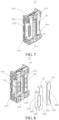
FIG. 7 is a schematic diagram of a structure of a bracket according to an embodiment of the present disclosure; -
FIG. 8 is an exploded view of a bracket according to an embodiment of the present disclosure; -
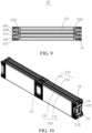
FIG. 9 is a cross-sectional view of the battery core module inFIG. 4 along a line A-A according to an embodiment of the present disclosure; -
FIG. 10 is a schematic diagram of another structure of a battery core unit according to an embodiment of the present disclosure; and -
FIG. 11 is an exploded view of a bracket of a battery core module that serves as an end portion of a battery core unit according to an embodiment of the present disclosure. -
- 1. battery core unit; 2. housing; 3. battery;
- 10. battery core module; 11. battery core group; 12. bracket; 13. intermediate connection sheet; 14. tail connection sheet; 15. supporting and fastening piece
- 111. battery core; 112. tab; 113. first battery core group; 114. second battery core group;
- 121. bracket body; 122. conductive sheet; 123. first bracket; 124. second bracket;
- 1211.
tab protruding hole 1212. supporting and limiting groove; 1213.elastic clamping button 1214. clamping convex button; 1215. insulating partition portion; 1216. first side surface; 1217. second side surface; 1218. third side surface; - 1221. first conductive sheet; 1222. second conductive sheet; 1223. tab avoiding hole; 1224. clamping hole; 1225. clamping recess.
- Features and examples of embodiments of various aspects of the present disclosure are described in detail below. In the following detail descriptions, a lot of specific details are proposed, to provide a thorough understanding of the present disclosure. However, it is apparent to a person skilled in the art that the following description of embodiments is intended only by way of example to aid the understanding of the present disclosure. In drawings and the following descriptions, at least parts of the well-known structures and techniques are not shown to avoid unnecessary interference with the present disclosure. To clearly show a related member, a size of a related structure may be enlarged. In addition, features, structures or characteristics described in the following may be combined in one or more embodiments in any appropriate manner.
- As shown in
FIG. 2 , abattery core unit 1 of the present disclosure includes multiplebattery core modules 10 connected in series, and thebattery core module 10 includes at least onebattery core group 11 andbrackets 12 arranged at two ends of thebattery core group 11. Thebattery core group 11 includesmultiple battery cores 111 stacked along a first direction, thebattery core 111 havetabs 112, and the first direction is a thickness direction of thebattery cores 111. Themultiple battery cores 111 in thebattery core group 11 are connected in parallel. An end portion of thebattery core group 11 is an end portion of thebattery core group 11 along a second direction, and the second direction is a lead-out direction of thetabs 112 of thebattery core 111. As shown inFIG. 7 and FIG. 8 , abracket 12 includes abracket body 121 andconductive sheets 122 mounted on thebracket body 121. Themultiple battery cores 111 of thebattery core group 11 are connected in parallel and connected to theconductive sheets 122 on thebracket 12, andconductive sheets 122 onbrackets 12 of adjacent twobattery core modules 10 are connected. This implements a series connection between the adjacent twobattery core modules 10. - As shown in
FIG. 6 andFIG. 8 ,tab protruding holes 1211 are provided on thebracket body 121, thetab protruding holes 1211 are provided corresponding totabs 112 of thebattery cores 111, and a number of thetab protruding holes 1211 is the same as a number of thebattery cores 111 of thebattery core group 11. Thetabs 112 of themultiple battery cores 111 in thebattery core group 11 extend through the correspondingtab protruding holes 1211 and are connected to theconductive sheets 122. Thetabs 112 and theconductive sheets 122 may be connected by welding or another connection method. To ensure reliability of the connection between thetabs 112 and theconductive sheets 122, thetabs 112 extend through the correspondingtab protruding holes 1211 and are bent to form bent portions, and bent portions are welded with theconductive sheets 122. In another embodiment, the number oftab protruding holes 1211 may be the same as a number of thebattery core group 11. Tabs of themultiple battery cores 111 in thebattery core group 11 are first welded together to form a converged tab, to be connected in parallel, and then extend through thetab protruding hole 1211 to be connected to theconductive sheets 122. - As shown in
FIG. 4 andFIG. 5 , abattery core module 10 further includes a supporting andfastening piece 15, and the supporting andfastening piece 15 is arranged between thebrackets 12 at the two ends of thebattery core group 11 to support and fasten thebrackets 12. As shown inFIG. 9 , supporting and limitinggrooves 1212 are provided on thebracket body 12, and the supporting andfastening piece 15 is inserted into the supporting and limitinggrooves 1212 to support and fasten thebrackets 12 at the two ends of thebattery core group 11, so that thebattery core group 11 and thebrackets 12 form abattery core module 10 with a stable structure. Specifically, the supporting andfastening piece 15 is an aluminum plate, and the supporting and limitinggrooves 1212 are V-shaped grooves. It can be understood that another metal plate may alternatively be used for the supporting and fastening piece. The V-shaped groove is designed to facilitate clamping and fastening of the supporting andfastening piece 15. To implement a better fastening and supporting and heat dissipation effect, the supporting andfastening piece 15 and a stacking surface of thebattery core 111 have a same shape and size. The stacking surface of thebattery core 111 is perpendicular to the first direction. In addition, the supporting andfastening piece 15 can also avoid shock and vibration of thetabs 112 of thebattery core 111 in a direction in which thetabs 112 are led out. The supporting andfastening piece 15 limits locations of thebrackets 12 at the two ends of thebattery core group 11, and prevents thebrackets 12 from moving and causing damage to thetabs 112. An adhesive layer is arranged on the supporting andfastening piece 15, and the supporting andfastening piece 15 is adhered to thebattery core group 11 by the adhesive layer. When thebattery core module 10 includes multiplebattery core groups 11, a supporting andfastening piece 15 may be arranged between adjacent twobattery core groups 11, adhesive layers may be arranged on both sides of the supporting andfastening piece 15, and the supporting andfastening piece 15 is adhered to the adjacentbattery core groups 11 by the adhesive layers. The adhesive layer is preferably hot melt adhesive, and it can be understood that a material selection of the adhesive layer is not limited to this. The adhesive layer may be provided based on an actual requirement, for example, may be provided only on one side of the supporting andfastening piece 15, or a partial area or an entire area of one side of the supporting andfastening piece 15, or a partial area or an entire area of both sides of the supporting andfastening piece 15. The supporting andfastening piece 15 implements supporting and fastening, and can transfer heat of thebattery core group 11 adhered to the supporting andfastening piece 15 to an external aluminum housing, and the aluminum housing further transfers the heat to a cooling apparatus to keep a battery temperature in a suitable range. - As shown in
FIG. 8 , theconductive sheet 122 includes a firstconductive sheet 1221 and a secondconductive sheet 1222 connected to the firstconductive sheet 1221. The firstconductive sheet 1221 and the secondconductive sheet 1222 are mutually connected and arranged at an angle. It may be understood that the firstconductive sheet 1221 and the secondconductive sheet 1222 may be connected by a conventional means such as welding or may be integrally formed. Atab avoiding hole 1223 is provided between the firstconductive sheet 1221 and the secondconductive sheet 1222. Thetab avoiding hole 1223 is provided corresponding to thetab protruding hole 1211. Thetab avoiding hole 1223 is provided at a junction of the firstconductive sheet 1221 and the secondconductive sheet 1222. When the firstconductive sheet 1221 and the secondconductive sheet 1222 are integrally formed, thetab avoiding hole 1223 is provided at a bending location of the firstconductive sheet 1221 and the secondconductive sheet 1222. Preferably, the firstconductive sheet 1221 is arranged perpendicularly to the secondconductive sheet 1222. In another embodiment, the firstconductive sheet 1221 and the secondconductive sheet 1222 may be arranged at a non-right angle. Thetab 112 of thebattery core 111 extends through thetab protruding hole 1211 and thetab avoiding hole 1223 in sequence and is connected to the firstconductive sheet 1221. - As shown in
FIG. 5 andFIG. 7 , thebracket body 121 has afirst side surface 1216, asecond side surface 1217 and athird side surface 1218. Thefirst side surface 1216 of thebracket body 121 is a surface close to thebattery core 111. Thesecond side surface 1217 of thebracket body 121 is a surface opposite to thefirst side surface 1216 and facing away from thebattery core 111. Thethird side surface 1218 of thebracket body 121 is a surface parallel to a lead-out direction of thetab 112 of the battery core, and thethird side surface 1218 is perpendicular to the first direction. The firstconductive sheet 1221 is arranged on thesecond side surface 1217 of thebracket body 121. The secondconductive sheet 1222 is arranged on thethird side surface 1218 of thebracket body 121. The supporting and limitinggroove 1212 is provided on thefirst side surface 1216 of thebracket body 121. Thetab 112 of thebattery core 111 of thebattery core group 11 extends through thetab protruding hole 1211 and thetab avoiding hole 1223 and is welded to the firstconductive sheet 1221. - As shown in
FIG. 2 andFIG. 3 , thebattery core unit 1 further includes anintermediate connection sheet 13, and adjacent twobattery core modules 10 are connected by theintermediate connection sheet 13. Theintermediate connection sheet 13 is connected to secondconductive sheets 1222 of the adjacent twobattery core modules 10. This forms a series connection between thebattery core modules 10. - As shown in
FIG. 8 , theconductive sheets 122 are connected to thebracket body 121 by a clamping mechanism. Specifically,elastic clamping buttons 1213 are provided on thebracket body 121, and theconductive sheet 122 is provided with clampingholes 1224 corresponding to theelastic clamping buttons 1213. The clamping holes 1224 of theconductive sheet 122 are pressed forcibly to clamp the clamping holes 1224 to outer sides of theelastic clamping buttons 1213, so that theconductive sheet 122 is mounted on thebracket body 121. Specifically, the clampingholes 1224 are provided on the secondconductive sheet 1222. To further ensure mounting stability of theconductive sheet 122 and thebracket body 121, aclamping recess 1225 is further provided on the firstconductive sheet 1221, and a clampingconvex button 1214 corresponding to theclamping recess 1225 is provided on thebracket body 121. Theclamping recess 1225 of the firstconductive sheet 1221 is engaged with the clampingconvex button 1214 of thebracket body 121 to further ensure stability of a connection between theconductive sheet 122 and thebracket body 121. - The
multiple battery cores 111 in thebattery core group 11 are adhered together by the adhesive layer. This increases rigidity and strength of the entirebattery core group 11. Tabs of a same polarity of thebattery cores 111 in thebattery core group 11 are led out from a same direction, and the tabs of the same polarity of thebattery cores 111 in thebattery core group 11 are connected to theconductive sheet 122 to form a parallel relationship after being led out from the same direction. Thebattery core 111 has a first polarity and a second polarity. The first polarity is a negative electrode, and the second polarity is a positive electrode. Alternatively, the first polarity is positive electrode, and the second polarity is a negative electrode. Therefore, thetabs 112 of thebattery core 111 are connected to theconductive sheet 122 after being led out, and theconductive sheet 122 also has the same polarity, namely, the first polarity or the second polarity, as thetab 112 of thebattery core 111. Therefore, thebattery core group 11 composed of thebattery core 111 and thebattery core module 10 also have the first polarity and the second polarity. Aconductive sheet 122 of a first polarity of onebattery core module 10 is connected to aconductive sheet 122 of a second polarity of another adjacentbattery core module 10. This implements a series connection between adjacent twobattery core modules 10. Aconductive sheet 122 of a first polarity of onebattery core module 10 is connected to aconductive sheet 122 of a second polarity of another adjacentbattery core module 10 by anintermediate connection sheet 13. - As shown in
FIG. 4 andFIG. 5 , when thebattery core module 10 includes multiplebattery core groups 11, the multiplebattery core groups 11 are arranged in the first direction. Polarities of adjacentbattery core groups 11 are arranged in reverse direction. Reverse arrangement means that, for example, a first end of onebattery core group 11 has a first polarity, and a second end of thebattery core group 11 has a second polarity; and a first end of an adjacentbattery core group 11 has a second polarity, and a second end of the adjacentbattery core group 11 has a first polarity. When thebattery core module 10 includes multiplebattery core groups 11, a supporting andfastening piece 15 is arranged between eachbattery core group 11. In addition, when thebattery core module 10 includes the multiplebattery core groups 11, aconductive sheet 122 is respectively connected to each of two ends of each battery core groups 11. To avoid short circuit caused by reverse polarity setting of adjacentbattery core groups 11, an insulatingpartition portion 1215 is further arranged on thebracket body 121, and the insulatingpartition portion 1215 is arranged betweenconductive sheets 122 connected to different battery core groups 11. - In an embodiment of the present disclosure, the
battery core unit 1 includes multiplebattery core modules 10 connected in series, thebattery core module 10 includes onebattery core group 11 andbrackets 12 arranged at two ends of thebattery core group 11, and oneconductive sheet 122 is arranged on thebracket 12.Tabs 112 of a same polarity ofmultiple battery cores 111 in thebattery core group 11 extend through atab protruding hole 1211 of thebracket 12 and atab avoiding hole 1223 of theconductive sheet 122, and are bent and connected to theconductive sheet 122. Anintermediate connection sheet 13 is connected to aconductive sheet 122 of one polarity of onebattery core group 11, and theintermediate connection sheet 13 is connected to aconductive sheet 122 of the other polarity of an adjacentbattery core group 11. Adjacentbattery core modules 10 are connected in series by theintermediate connection sheet 13. - In an embodiment of the present disclosure, a
battery core unit 1 includes multiplebattery core modules 10 connected in series, and thebattery core module 10 includes multiplebattery core groups 11 andbrackets 12 arranged at two ends of each of the battery core groups 11. The multiplebattery core groups 11 are arranged along a first direction. A plurality ofconductive sheets 122 are arranged on thebracket 12. A number of theconductive sheets 122 is the same as a number of the plurality of battery core groups 11. Adjacentconductive sheets 122 arranged along the first direction have opposite polarities. Aconductive sheet 122 of onebattery core module 10 is connected to aconductive sheet 122 of another adjacentbattery core module 10 by anintermediate connection sheet 13. Thebattery core unit 1 further includes atail connection sheet 14, and thetail connection sheet 14 is mounted on abracket 12 of abattery core module 10 that serves as an end portion of thebattery core unit 1. Thetail connection sheet 14 can connect different polarities of thebattery core module 10 that serve as the end portion of thebattery core unit 1, to implement a series connection of the entire battery core unit. Thetail connection sheet 14 may be a transverse connection sheet or a straight connection sheet. Thetail connection sheet 14 is connected to the multiple conductive sheets on thebracket 12. Further, as shown inFIG. 10 andFIG. 11 , thetail connection sheet 14 may be integrally formed with the multipleconductive sheets 122 on thebracket 12. As shown inFIG. 11 , there are twotail connection sheets 14. A specific number oftail connection sheets 14 is not limited to this. - As shown in
FIG. 4 , specifically, thebattery core module 10 includes twobattery core groups 11 andbrackets 12 arranged at two ends of thebattery core group 11. A number ofbattery core groups 11 is not limited to this, and may be increased based on an actual requirement. As shown inFIG. 4 andFIG. 5 , that thebattery core module 10 includes two sets ofbattery core groups 11 is used as an example for description. Thebattery core module 10 includes a firstbattery core group 113 and a secondbattery core group 114, and each of the firstbattery core group 113 and the secondbattery core group 114 includesmultiple battery cores 111. Thebattery core module 10 also includesbrackets 12 that are arranged at two ends of the firstbattery core group 113 and the secondbattery core group 114 at the same time and that include afirst bracket 123 and a second bracket 124. Thefirst bracket 123 and the second bracket 124 have a same structure and are arranged opposite to each other. Twoconductive sheets 122 are arranged on each of thefirst bracket 123 and the second bracket 124.Tabs 112 of a first polarity of themultiple battery cores 111 in the firstbattery core group 113 extend through atab protruding hole 1211 of thefirst bracket 123 and thetab avoiding hole 1223 of oneconductive sheet 122, and are bent and connected to theconductive sheet 122.Tabs 112 of a second polarity of themultiple battery cores 111 in the secondbattery core group 114 extend through atab protruding hole 1211 of thefirst bracket 123 and atab avoiding hole 1223 of the otherconductive sheet 122, and are bent and connected to the otherconductive sheet 122. A specific connection manner between thetabs 112 of thebattery cores 111 and theconductive sheet 122 after thetabs 112 are led out may be welding or another connection manner that can implement an electrical connection. In addition,tabs 112 of a second polarity of themultiple battery cores 111 in the firstbattery core group 113 extend through atab protruding hole 1211 of the second bracket 124 and atab avoiding hole 1223 of oneconductive sheet 122, and are bent and connected to theconductive sheet 122.Tabs 112 of a first polarity of themultiple battery cores 111 in the secondbattery core group 114 extend through atab protruding hole 1211 of the second bracket 124 and atab avoiding hole 1223 of the otherconductive sheet 122, and are bent and connected to the otherconductive sheet 122. As shown inFIG. 4 andFIG. 9 , thefirst bracket 123 and the second bracket 124 are arranged opposite to each other. Supporting and limitinggrooves 1212 are provided on thefirst bracket 123 and the second bracket 124, and a supporting andfastening piece 15 is inserted into the supporting and limitinggroove 1212 of thefirst bracket 123 and the supporting and limitinggroove 1212 of the second bracket 124 to support and fasten thebattery core module 10. The supporting andfastening piece 15 is disposed at an intermediate location of thebattery core module 10, namely, between the firstbattery core group 113 and the secondbattery core group 114. The supporting andfastening piece 15 is an aluminum plate, both sides of the aluminum plate are provided with adhesive layers, and the aluminum plate is adhered to the firstbattery core group 113 and the secondbattery core group 114 by the adhesive layers. The adhesive layer may be provided based on an actual requirement, for example, may be provided only on one side of the aluminum plate, or a partial area or an entire area of one side of the aluminum plate, or a partial area or an entire area of both sides of the aluminum plate. Afterbattery core module 10 are assembled, multiple adjacentbattery core modules 10 are connected byintermediate connection sheets 13. End portions of opposite polarities of adjacentbattery core modules 10 are connected by theintermediate connection sheet 13. For example, anintermediate connection sheet 13 is connected to aconductive sheet 122 of a first polarity of abattery core module 10, and, theintermediate connection sheet 13 is also connected to aconductive sheet 122 of a second polarity of an adjacentbattery core module 10, to implement a series connection ofbattery core groups 11 in adjacentbattery core modules 10. When thebattery core module 10 includes the multiplebattery core groups 11, thebattery core unit 1 further includes atail connection sheet 14. Thetail connection sheet 14 is arranged on asecond side surface 1217 of abracket 12 of abattery core module 10 that serves as an end portion of thebattery core unit 1. Thetail connection sheet 14 connects tabs of opposite polarities ofbattery core groups 11 of thebattery core module 10 that serves as the end portion of thebattery core unit 1, to implement an overall series connection of multiplebattery core modules 10. - The
battery core modules 10 connected in series in the present disclosure may be arranged based on an actual requirement. Thebattery core groups 11 are assembled into thebattery core module 10, to become a standardizedbattery core module 10, and standardized battery core modules may be further arbitrarily connected, based on actual requirement, in series to form battery core units with different sizes, and then form batteries with different sizes. The battery core unit of the present disclosure is simple to install, has high grouping efficiency, and has extremely high space utilization rate in a battery case that can be as high as 98%. In addition, the battery core modules constituting the battery core unit are highly replicable. This is convenient to form battery packs with different arrangements and standards. - As shown in
FIG 1 , the present disclosure further discloses abattery 3, which includes thebattery core unit 1 of any of the foregoing embodiments and ahousing 2 configured for accommodating thebattery core unit 1. The present disclosure further discloses a vehicle, including thebattery core unit 1 of any of the foregoing embodiments and a chassis structure configured for accommodating thebattery core unit 1. - Orientation terms appearing in the description of the present disclosure means directions shown in the figures and are not intended to limit a specific structure of the present disclosure. In addition, unless otherwise explicitly specified or defined, the terms such as "mount" and "connect" should be understood in a broad sense. For example, a connection may be a fixed connection, a detachable connection, or an integral connection; or a connection may be a direct connection, or an indirect connection. A person of ordinary skill in the art may understand specific meanings of the foregoing terms in the present disclosure according to specific situations.
- The foregoing embodiments show only several implementations of the present disclosure and are described in detail, which, however, are not to be construed as a limitation to the patent scope of the present disclosure. It should be noted that for a person of ordinary skill in the art, several transformations and improvements can be made without departing from the idea of the present disclosure. These transformations and improvements belong to the protection scope of the present disclosure. Therefore, the protection scope of the patent of the present disclosure shall be subject to the appended claims.
Claims (16)
- A battery core unit (1), comprising:a plurality of battery core modules (10), the plurality of battery core modules (10) being connected in series;each of the battery core module (10) comprising at least one battery core group (11) and brackets (12) arranged at two ends of the at least one battery core group (11); each battery core group (11) comprising a plurality of battery cores (111) stacked along a first direction, and the plurality of battery cores (111) being connected in parallel; the first direction being a thickness direction of the battery core (111);the bracket (12) comprising a bracket body (121) and a conductive sheet (122) mounted on the bracket body (121); at least one tab protruding hole (1211) being provided on the bracket body (121), and a tab (112) of the battery core (111) extending through the tab protruding hole (1211) and being connected to the conductive sheet (122); and the battery core module (10) further comprising a supporting and fastening piece (15), the supporting and fastening piece (15) being arranged between the brackets (12) at the two ends of the at least one battery core group (11).
- The battery core unit (1) according to claim 1, whereinthe conductive sheet (122) comprises a first conductive sheet (1221) and a second conductive sheet (1222); the first conductive sheet (1221) and the second conductive sheet (1222) are mutually connected and arranged at an angle;a tab avoiding hole (1223) is provided between the first conductive sheet (1221) and the second conductive sheet (1222); andthe tab (112) of the battery core (111) extends through the tab protruding hole (1211) and the tab avoiding hole (1223) in sequence and is connected to the first conductive sheet (1221).
- The battery core unit (1) according to claim 2, whereinthe bracket body (121) has a first side surface (1216), a second side surface (1217), and a third side surface (1218); the first side surface (1216) is a surface close to the battery core (111), the second side surface (1217) is a surface opposite to the first side surface (1216) and facing away from the battery core (111), and the third side surface (1218) is a surface parallel to a lead-out direction of the tab of the battery core (111) and perpendicular to the first direction;the first conductive sheet (1221) is arranged on the second side surface (1217); and the second conductive sheet (1222) is arranged on the third side surface (1218).
- The battery core unit (1) according to claim 2 or 3, further comprising:
an intermediate connection sheet (13) respectively connected to second conductive sheets (1222) on brackets (12) of adjacent battery core modules (10), wherein the adjacent battery core modules (10) are connected in series by the intermediate connection sheet (13). - The battery core unit (1) according to any one of claims 1 to 4, wherein
supporting and limiting grooves (1212) are provided on the bracket body (121), and the supporting and fastening piece (15) is inserted into the supporting and limiting grooves (1212). - The battery core unit (1) according to claim 5, wherein
the supporting and limiting grooves (1212) are V-shaped grooves; and the supporting and fastening piece (15) is an aluminum plate. - The battery core unit (1) according to any one of claims 1 to 6, whereinthe supporting and fastening piece (15) and the battery core group (11) are stacked and arranged along the first direction; andan adhesive layer is arranged on the supporting and fastening piece (15), and the supporting and fastening piece (15) is adhered to the battery core group (11) by the adhesive layer.
- The battery core unit (1) according to any one of claims 1 to 7, wherein
the bracket body (121) is connected to the conductive sheet (122) by a clamping structure. - The battery core unit (1) according to any one of claims 1 to 3, or claims of 5 to 8, whereinthe at least one battery core group (11) is one battery core group (11), the brackets (12) is arranged at the two ends of the battery core group (11), and each bracket (12) is provided with one conductive sheet (122);the battery core unit (1) further comprising an intermediate connection sheet (13); and a conductive sheet of a first polarity of one battery core module (10) being connected to a conductive sheet (122) of a second polarity of an adjacent battery core module (10) by the intermediate connection sheet (13).
- The battery core unit (1) according to any one of claims 1 to 3, or claims of 5 to 8, whereinthe at least one battery core group (11) is a plurality of battery core groups (11), the plurality of battery core groups (11) are arranged along the first direction, and the brackets (12) are arranged at the two ends of the plurality of battery core groups (11);each bracket (12) is provided with a plurality of conductive sheets (122); a number of the conductive sheets (122) being the same as a number of the plurality of battery core groups (11); adjacent conductive sheets (122) arranged along the first direction having opposite polarities;the battery core unit (1) further comprising an intermediate connection sheet (13); a conductive sheet (122) of one battery core module (10) being connected to a conductive sheet (122) of an adjacent battery core module (10) by the intermediate connection sheet (13); andthe battery core unit (1) further comprising a tail connection sheet (14), and the tail connection sheet (14) being mounted on a bracket (12) of a battery core module (10) that serves as an end portion of the battery core unit (1).
- The battery core unit (1) according to claim 10, wherein
the tail connection sheet (14) is integrally formed with the plurality of conductive sheets (122) on the bracket (12). - The battery core unit (1) according to claim 10 or 11, wherein
an insulating partition portion (1215) is arranged on the bracket body (121), and the insulating partition portion (1215) is arranged between conductive sheets (122) connected to different battery core groups (11). - The battery core unit (1) according to any one of claims 1 to 12, wherein
the tab (112) extends through the tab protruding hole (1211) and is bent to form a bent portion, and the bent portion is connected to the conductive sheet (122) by welding. - The battery core unit (1) according to any one of claims 1 to 13, wherein
elastic clamping buttons (1213) are provided on the bracket body (121), the conductive sheet (122) is provided with clamping holes (1224) corresponding to the elastic clamping buttons (1213), and the conductive sheets (122) are mounted on the bracket body (121) by the clamping holes (1224) and the elastic clamping buttons (1213). - A battery (3), comprising a housing (2), the battery (3) further comprising the battery core unit (1) according to any one of claims 1 to 14, and the battery core unit (1) being accommodated in the housing (2).
- A vehicle, comprising the battery core unit (1) according to any one of claims 1 to 14 and a chassis structure configured for accommodating the battery core unit (1).
Applications Claiming Priority (2)
| Application Number | Priority Date | Filing Date | Title |
|---|---|---|---|
| CN202122922163.3U CN216529247U (en) | 2021-11-24 | 2021-11-24 | Electricity core unit, battery and car |
| PCT/CN2022/133706 WO2023093759A1 (en) | 2021-11-24 | 2022-11-23 | Battery cell unit, battery, and vehicle |
Publications (2)
| Publication Number | Publication Date |
|---|---|
| EP4379929A1 true EP4379929A1 (en) | 2024-06-05 |
| EP4379929A4 EP4379929A4 (en) | 2025-03-12 |
Family
ID=81464011
Family Applications (1)
| Application Number | Title | Priority Date | Filing Date |
|---|---|---|---|
| EP22897842.5A Pending EP4379929A4 (en) | 2021-11-24 | 2022-11-23 | BATTERY CELL UNIT, BATTERY AND VEHICLE |
Country Status (8)
| Country | Link |
|---|---|
| US (1) | US20240222811A1 (en) |
| EP (1) | EP4379929A4 (en) |
| JP (1) | JP7799044B2 (en) |
| KR (1) | KR20240035878A (en) |
| CN (1) | CN216529247U (en) |
| AU (1) | AU2022397673B2 (en) |
| CA (1) | CA3232316A1 (en) |
| WO (1) | WO2023093759A1 (en) |
Families Citing this family (5)
| Publication number | Priority date | Publication date | Assignee | Title |
|---|---|---|---|---|
| CN216529247U (en) * | 2021-11-24 | 2022-05-13 | 比亚迪股份有限公司 | Electricity core unit, battery and car |
| CN116826277B (en) * | 2022-03-21 | 2024-11-15 | 比亚迪股份有限公司 | Battery cell supporting structure, battery cell assembly, battery pack and vehicle |
| US12456855B2 (en) * | 2022-05-26 | 2025-10-28 | GM Global Technology Operations LLC | Thermally conducting bracket for busbar to cold plate heat transfer |
| CN115000592A (en) * | 2022-06-20 | 2022-09-02 | 万向一二三股份公司 | Novel soft-package square-shell battery |
| CN118040255A (en) * | 2022-11-08 | 2024-05-14 | 厦门新能达科技有限公司 | Battery cell assembly, electrochemical device and electric equipment |
Family Cites Families (14)
| Publication number | Priority date | Publication date | Assignee | Title |
|---|---|---|---|---|
| JP4784067B2 (en) * | 2004-10-29 | 2011-09-28 | トヨタ自動車株式会社 | Power storage module |
| GB2535546B (en) * | 2015-02-18 | 2017-09-20 | Tata Motors European Technical Ct Plc | Battery modules and methods for their manufacture |
| KR102381777B1 (en) * | 2015-02-25 | 2022-04-01 | 삼성에스디아이 주식회사 | Battery pack |
| KR102102927B1 (en) * | 2016-10-06 | 2020-04-21 | 주식회사 엘지화학 | Battery module, battery pack comprising the battery module and vehicle comprising the battery pack |
| CN110224099B (en) * | 2018-03-01 | 2020-09-01 | 宁德时代新能源科技股份有限公司 | Secondary battery and automobile |
| CN109216626B (en) * | 2018-11-15 | 2023-08-25 | 桑顿新能源科技(长沙)有限公司 | Power battery module middle frame and power battery module structure |
| CN111312952B (en) * | 2019-12-26 | 2022-11-25 | 湖北锂诺新能源科技有限公司 | Soft package module utmost point ear fixed plate connection structure |
| KR102938463B1 (en) * | 2020-01-22 | 2026-03-11 | 주식회사 엘지에너지솔루션 | Battery module, battery rack and energy storage system comprising the battery module |
| CN111477801A (en) * | 2020-04-30 | 2020-07-31 | 昆山宝创新能源科技有限公司 | Battery module, battery pack and vehicle |
| CN111477799A (en) * | 2020-04-30 | 2020-07-31 | 昆山宝创新能源科技有限公司 | Battery module, battery pack and vehicle |
| CN111477830A (en) * | 2020-04-30 | 2020-07-31 | 昆山宝创新能源科技有限公司 | Battery module and have its battery module and car |
| CN113161672A (en) * | 2021-04-29 | 2021-07-23 | 恒大新能源技术(深圳)有限公司 | Battery module and battery pack with same |
| CN216529247U (en) * | 2021-11-24 | 2022-05-13 | 比亚迪股份有限公司 | Electricity core unit, battery and car |
| CN216720116U (en) * | 2021-11-24 | 2022-06-10 | 比亚迪股份有限公司 | Battery cell unit, battery and vehicle |
-
2021
- 2021-11-24 CN CN202122922163.3U patent/CN216529247U/en active Active
-
2022
- 2022-11-23 JP JP2024513109A patent/JP7799044B2/en active Active
- 2022-11-23 EP EP22897842.5A patent/EP4379929A4/en active Pending
- 2022-11-23 WO PCT/CN2022/133706 patent/WO2023093759A1/en not_active Ceased
- 2022-11-23 CA CA3232316A patent/CA3232316A1/en active Pending
- 2022-11-23 KR KR1020247006108A patent/KR20240035878A/en active Pending
- 2022-11-23 AU AU2022397673A patent/AU2022397673B2/en active Active
-
2024
- 2024-03-18 US US18/608,529 patent/US20240222811A1/en active Pending
Also Published As
| Publication number | Publication date |
|---|---|
| US20240222811A1 (en) | 2024-07-04 |
| CN216529247U (en) | 2022-05-13 |
| WO2023093759A1 (en) | 2023-06-01 |
| AU2022397673A1 (en) | 2024-03-28 |
| JP2024541169A (en) | 2024-11-08 |
| CA3232316A1 (en) | 2023-06-01 |
| EP4379929A4 (en) | 2025-03-12 |
| JP7799044B2 (en) | 2026-01-14 |
| AU2022397673B2 (en) | 2026-01-08 |
| KR20240035878A (en) | 2024-03-18 |
Similar Documents
| Publication | Publication Date | Title |
|---|---|---|
| EP4379929A1 (en) | Battery cell unit, battery, and vehicle | |
| CN108448041B (en) | A soft-pack lithium-ion battery module and connection method | |
| EP2416439B1 (en) | Battery module having excellent heat dissipation ability and battery pack employed with the same | |
| EP1812982B1 (en) | Secondary battery pack having configuration of alternative orientation | |
| EP3726611B1 (en) | Battery module and battery pack | |
| EP3764422B1 (en) | Sampling circuit board for battery module, and battery module | |
| CN209786120U (en) | Secondary batteries and battery modules | |
| WO2010114318A2 (en) | Battery module having flexibility in design structure of module and medium to large sized battery pack including the same | |
| US12160019B2 (en) | Battery module and battery pack | |
| CN114094254A (en) | Battery module | |
| JP2025503745A (en) | Battery module and battery pack including same | |
| JP7695456B1 (en) | Connection member, cell module and energy storage battery pack | |
| CN213816364U (en) | Battery modules and battery packs | |
| US12126049B2 (en) | Battery module | |
| CN211828998U (en) | Bus bar for battery module and battery assembly thereof | |
| EP4258440A1 (en) | Battery module and battery pack | |
| CN218472176U (en) | Battery modules and battery packs | |
| WO2025208721A1 (en) | Battery assembly structure and battery module | |
| CN223140981U (en) | Battery pack and power device | |
| CN222072117U (en) | CTP soft package module utmost point ear connecting piece | |
| CN111477800A (en) | Battery Modules, Battery Packs and Vehicles | |
| CN221947234U (en) | Energy storage battery system | |
| CN218788476U (en) | Battery pack | |
| JP7789122B2 (en) | Composite Battery Assembly Structure | |
| CN220420800U (en) | Mounting assembly and battery pack |
Legal Events
| Date | Code | Title | Description |
|---|---|---|---|
| STAA | Information on the status of an ep patent application or granted ep patent |
Free format text: STATUS: THE INTERNATIONAL PUBLICATION HAS BEEN MADE |
|
| PUAI | Public reference made under article 153(3) epc to a published international application that has entered the european phase |
Free format text: ORIGINAL CODE: 0009012 |
|
| STAA | Information on the status of an ep patent application or granted ep patent |
Free format text: STATUS: REQUEST FOR EXAMINATION WAS MADE |
|
| 17P | Request for examination filed |
Effective date: 20240229 |
|
| AK | Designated contracting states |
Kind code of ref document: A1 Designated state(s): AL AT BE BG CH CY CZ DE DK EE ES FI FR GB GR HR HU IE IS IT LI LT LU LV MC ME MK MT NL NO PL PT RO RS SE SI SK SM TR |
|
| RIN1 | Information on inventor provided before grant (corrected) |
Inventor name: CHEN, YAOLEI Inventor name: ZHOU, YANFEI Inventor name: CHEN, WEI Inventor name: LANG, XIAOQIANG Inventor name: GUO, YONGMING |
|
| DAV | Request for validation of the european patent (deleted) | ||
| DAX | Request for extension of the european patent (deleted) | ||
| A4 | Supplementary search report drawn up and despatched |
Effective date: 20250206 |
|
| RIC1 | Information provided on ipc code assigned before grant |
Ipc: H01M 50/249 20210101ALI20250131BHEP Ipc: H01M 50/209 20210101ALI20250131BHEP Ipc: H01M 50/204 20210101ALI20250131BHEP Ipc: H01M 50/264 20210101ALI20250131BHEP Ipc: H01M 50/211 20210101ALI20250131BHEP Ipc: H01M 50/503 20210101ALI20250131BHEP Ipc: H01M 50/258 20210101ALI20250131BHEP Ipc: H01M 50/244 20210101AFI20250131BHEP |