EP4379907A1 - Battery pack - Google Patents
Battery pack Download PDFInfo
- Publication number
- EP4379907A1 EP4379907A1 EP23213800.8A EP23213800A EP4379907A1 EP 4379907 A1 EP4379907 A1 EP 4379907A1 EP 23213800 A EP23213800 A EP 23213800A EP 4379907 A1 EP4379907 A1 EP 4379907A1
- Authority
- EP
- European Patent Office
- Prior art keywords
- cooling
- plate
- refrigerant
- battery pack
- frame
- Prior art date
- Legal status (The legal status is an assumption and is not a legal conclusion. Google has not performed a legal analysis and makes no representation as to the accuracy of the status listed.)
- Granted
Links
Images






Classifications
-
- H—ELECTRICITY
- H01—ELECTRIC ELEMENTS
- H01M—PROCESSES OR MEANS, e.g. BATTERIES, FOR THE DIRECT CONVERSION OF CHEMICAL ENERGY INTO ELECTRICAL ENERGY
- H01M10/00—Secondary cells; Manufacture thereof
- H01M10/60—Heating or cooling; Temperature control
- H01M10/61—Types of temperature control
- H01M10/613—Cooling or keeping cold
-
- H—ELECTRICITY
- H01—ELECTRIC ELEMENTS
- H01M—PROCESSES OR MEANS, e.g. BATTERIES, FOR THE DIRECT CONVERSION OF CHEMICAL ENERGY INTO ELECTRICAL ENERGY
- H01M10/00—Secondary cells; Manufacture thereof
- H01M10/60—Heating or cooling; Temperature control
- H01M10/65—Means for temperature control structurally associated with the cells
- H01M10/655—Solid structures for heat exchange or heat conduction
- H01M10/6556—Solid parts with flow channel passages or pipes for heat exchange
-
- H—ELECTRICITY
- H01—ELECTRIC ELEMENTS
- H01M—PROCESSES OR MEANS, e.g. BATTERIES, FOR THE DIRECT CONVERSION OF CHEMICAL ENERGY INTO ELECTRICAL ENERGY
- H01M10/00—Secondary cells; Manufacture thereof
- H01M10/60—Heating or cooling; Temperature control
- H01M10/62—Heating or cooling; Temperature control specially adapted for specific applications
- H01M10/625—Vehicles
-
- H—ELECTRICITY
- H01—ELECTRIC ELEMENTS
- H01M—PROCESSES OR MEANS, e.g. BATTERIES, FOR THE DIRECT CONVERSION OF CHEMICAL ENERGY INTO ELECTRICAL ENERGY
- H01M10/00—Secondary cells; Manufacture thereof
- H01M10/60—Heating or cooling; Temperature control
- H01M10/65—Means for temperature control structurally associated with the cells
- H01M10/655—Solid structures for heat exchange or heat conduction
- H01M10/6554—Rods or plates
-
- H—ELECTRICITY
- H01—ELECTRIC ELEMENTS
- H01M—PROCESSES OR MEANS, e.g. BATTERIES, FOR THE DIRECT CONVERSION OF CHEMICAL ENERGY INTO ELECTRICAL ENERGY
- H01M10/00—Secondary cells; Manufacture thereof
- H01M10/60—Heating or cooling; Temperature control
- H01M10/65—Means for temperature control structurally associated with the cells
- H01M10/656—Means for temperature control structurally associated with the cells characterised by the type of heat-exchange fluid
- H01M10/6567—Liquids
- H01M10/6568—Liquids characterised by flow circuits, e.g. loops, located externally to the cells or cell casings
-
- H—ELECTRICITY
- H01—ELECTRIC ELEMENTS
- H01M—PROCESSES OR MEANS, e.g. BATTERIES, FOR THE DIRECT CONVERSION OF CHEMICAL ENERGY INTO ELECTRICAL ENERGY
- H01M50/00—Constructional details or processes of manufacture of the non-active parts of electrochemical cells other than fuel cells, e.g. hybrid cells
- H01M50/10—Primary casings; Jackets or wrappings
- H01M50/183—Sealing members
- H01M50/186—Sealing members characterised by the disposition of the sealing members
-
- H—ELECTRICITY
- H01—ELECTRIC ELEMENTS
- H01M—PROCESSES OR MEANS, e.g. BATTERIES, FOR THE DIRECT CONVERSION OF CHEMICAL ENERGY INTO ELECTRICAL ENERGY
- H01M50/00—Constructional details or processes of manufacture of the non-active parts of electrochemical cells other than fuel cells, e.g. hybrid cells
- H01M50/20—Mountings; Secondary casings or frames; Racks, modules or packs; Suspension devices; Shock absorbers; Transport or carrying devices; Holders
- H01M50/204—Racks, modules or packs for multiple batteries or multiple cells
-
- H—ELECTRICITY
- H01—ELECTRIC ELEMENTS
- H01M—PROCESSES OR MEANS, e.g. BATTERIES, FOR THE DIRECT CONVERSION OF CHEMICAL ENERGY INTO ELECTRICAL ENERGY
- H01M50/00—Constructional details or processes of manufacture of the non-active parts of electrochemical cells other than fuel cells, e.g. hybrid cells
- H01M50/20—Mountings; Secondary casings or frames; Racks, modules or packs; Suspension devices; Shock absorbers; Transport or carrying devices; Holders
- H01M50/204—Racks, modules or packs for multiple batteries or multiple cells
- H01M50/207—Racks, modules or packs for multiple batteries or multiple cells characterised by their shape
- H01M50/209—Racks, modules or packs for multiple batteries or multiple cells characterised by their shape adapted for prismatic or rectangular cells
-
- H—ELECTRICITY
- H01—ELECTRIC ELEMENTS
- H01M—PROCESSES OR MEANS, e.g. BATTERIES, FOR THE DIRECT CONVERSION OF CHEMICAL ENERGY INTO ELECTRICAL ENERGY
- H01M50/00—Constructional details or processes of manufacture of the non-active parts of electrochemical cells other than fuel cells, e.g. hybrid cells
- H01M50/20—Mountings; Secondary casings or frames; Racks, modules or packs; Suspension devices; Shock absorbers; Transport or carrying devices; Holders
- H01M50/218—Mountings; Secondary casings or frames; Racks, modules or packs; Suspension devices; Shock absorbers; Transport or carrying devices; Holders characterised by the material
- H01M50/22—Mountings; Secondary casings or frames; Racks, modules or packs; Suspension devices; Shock absorbers; Transport or carrying devices; Holders characterised by the material of the casings or racks
- H01M50/231—Mountings; Secondary casings or frames; Racks, modules or packs; Suspension devices; Shock absorbers; Transport or carrying devices; Holders characterised by the material of the casings or racks having a layered structure
-
- H—ELECTRICITY
- H01—ELECTRIC ELEMENTS
- H01M—PROCESSES OR MEANS, e.g. BATTERIES, FOR THE DIRECT CONVERSION OF CHEMICAL ENERGY INTO ELECTRICAL ENERGY
- H01M50/00—Constructional details or processes of manufacture of the non-active parts of electrochemical cells other than fuel cells, e.g. hybrid cells
- H01M50/20—Mountings; Secondary casings or frames; Racks, modules or packs; Suspension devices; Shock absorbers; Transport or carrying devices; Holders
- H01M50/233—Mountings; Secondary casings or frames; Racks, modules or packs; Suspension devices; Shock absorbers; Transport or carrying devices; Holders characterised by physical properties of casings or racks, e.g. dimensions
- H01M50/24—Mountings; Secondary casings or frames; Racks, modules or packs; Suspension devices; Shock absorbers; Transport or carrying devices; Holders characterised by physical properties of casings or racks, e.g. dimensions adapted for protecting batteries from their environment, e.g. from corrosion
-
- H—ELECTRICITY
- H01—ELECTRIC ELEMENTS
- H01M—PROCESSES OR MEANS, e.g. BATTERIES, FOR THE DIRECT CONVERSION OF CHEMICAL ENERGY INTO ELECTRICAL ENERGY
- H01M50/00—Constructional details or processes of manufacture of the non-active parts of electrochemical cells other than fuel cells, e.g. hybrid cells
- H01M50/20—Mountings; Secondary casings or frames; Racks, modules or packs; Suspension devices; Shock absorbers; Transport or carrying devices; Holders
- H01M50/244—Secondary casings; Racks; Suspension devices; Carrying devices; Holders characterised by their mounting method
-
- H—ELECTRICITY
- H01—ELECTRIC ELEMENTS
- H01M—PROCESSES OR MEANS, e.g. BATTERIES, FOR THE DIRECT CONVERSION OF CHEMICAL ENERGY INTO ELECTRICAL ENERGY
- H01M50/00—Constructional details or processes of manufacture of the non-active parts of electrochemical cells other than fuel cells, e.g. hybrid cells
- H01M50/20—Mountings; Secondary casings or frames; Racks, modules or packs; Suspension devices; Shock absorbers; Transport or carrying devices; Holders
- H01M50/249—Mountings; Secondary casings or frames; Racks, modules or packs; Suspension devices; Shock absorbers; Transport or carrying devices; Holders specially adapted for aircraft or vehicles, e.g. cars or trains
-
- H—ELECTRICITY
- H01—ELECTRIC ELEMENTS
- H01M—PROCESSES OR MEANS, e.g. BATTERIES, FOR THE DIRECT CONVERSION OF CHEMICAL ENERGY INTO ELECTRICAL ENERGY
- H01M50/00—Constructional details or processes of manufacture of the non-active parts of electrochemical cells other than fuel cells, e.g. hybrid cells
- H01M50/20—Mountings; Secondary casings or frames; Racks, modules or packs; Suspension devices; Shock absorbers; Transport or carrying devices; Holders
- H01M50/258—Modular batteries; Casings provided with means for assembling
-
- H—ELECTRICITY
- H01—ELECTRIC ELEMENTS
- H01M—PROCESSES OR MEANS, e.g. BATTERIES, FOR THE DIRECT CONVERSION OF CHEMICAL ENERGY INTO ELECTRICAL ENERGY
- H01M50/00—Constructional details or processes of manufacture of the non-active parts of electrochemical cells other than fuel cells, e.g. hybrid cells
- H01M50/20—Mountings; Secondary casings or frames; Racks, modules or packs; Suspension devices; Shock absorbers; Transport or carrying devices; Holders
- H01M50/262—Mountings; Secondary casings or frames; Racks, modules or packs; Suspension devices; Shock absorbers; Transport or carrying devices; Holders with fastening means, e.g. locks
-
- H—ELECTRICITY
- H01—ELECTRIC ELEMENTS
- H01M—PROCESSES OR MEANS, e.g. BATTERIES, FOR THE DIRECT CONVERSION OF CHEMICAL ENERGY INTO ELECTRICAL ENERGY
- H01M50/00—Constructional details or processes of manufacture of the non-active parts of electrochemical cells other than fuel cells, e.g. hybrid cells
- H01M50/20—Mountings; Secondary casings or frames; Racks, modules or packs; Suspension devices; Shock absorbers; Transport or carrying devices; Holders
- H01M50/289—Mountings; Secondary casings or frames; Racks, modules or packs; Suspension devices; Shock absorbers; Transport or carrying devices; Holders characterised by spacing elements or positioning means within frames, racks or packs
-
- H—ELECTRICITY
- H01—ELECTRIC ELEMENTS
- H01M—PROCESSES OR MEANS, e.g. BATTERIES, FOR THE DIRECT CONVERSION OF CHEMICAL ENERGY INTO ELECTRICAL ENERGY
- H01M50/00—Constructional details or processes of manufacture of the non-active parts of electrochemical cells other than fuel cells, e.g. hybrid cells
- H01M50/30—Arrangements for facilitating escape of gases
- H01M50/35—Gas exhaust passages comprising elongated, tortuous or labyrinth-shaped exhaust passages
- H01M50/358—External gas exhaust passages located on the battery cover or case
-
- H—ELECTRICITY
- H01—ELECTRIC ELEMENTS
- H01M—PROCESSES OR MEANS, e.g. BATTERIES, FOR THE DIRECT CONVERSION OF CHEMICAL ENERGY INTO ELECTRICAL ENERGY
- H01M50/00—Constructional details or processes of manufacture of the non-active parts of electrochemical cells other than fuel cells, e.g. hybrid cells
- H01M50/50—Current conducting connections for cells or batteries
- H01M50/502—Interconnectors for connecting terminals of adjacent batteries; Interconnectors for connecting cells outside a battery casing
- H01M50/507—Interconnectors for connecting terminals of adjacent batteries; Interconnectors for connecting cells outside a battery casing comprising an arrangement of two or more busbars within a container structure, e.g. busbar modules
-
- H—ELECTRICITY
- H01—ELECTRIC ELEMENTS
- H01M—PROCESSES OR MEANS, e.g. BATTERIES, FOR THE DIRECT CONVERSION OF CHEMICAL ENERGY INTO ELECTRICAL ENERGY
- H01M2220/00—Batteries for particular applications
- H01M2220/20—Batteries in motive systems, e.g. vehicle, ship, plane
-
- H—ELECTRICITY
- H01—ELECTRIC ELEMENTS
- H01M—PROCESSES OR MEANS, e.g. BATTERIES, FOR THE DIRECT CONVERSION OF CHEMICAL ENERGY INTO ELECTRICAL ENERGY
- H01M50/00—Constructional details or processes of manufacture of the non-active parts of electrochemical cells other than fuel cells, e.g. hybrid cells
- H01M50/50—Current conducting connections for cells or batteries
- H01M50/502—Interconnectors for connecting terminals of adjacent batteries; Interconnectors for connecting cells outside a battery casing
-
- Y—GENERAL TAGGING OF NEW TECHNOLOGICAL DEVELOPMENTS; GENERAL TAGGING OF CROSS-SECTIONAL TECHNOLOGIES SPANNING OVER SEVERAL SECTIONS OF THE IPC; TECHNICAL SUBJECTS COVERED BY FORMER USPC CROSS-REFERENCE ART COLLECTIONS [XRACs] AND DIGESTS
- Y02—TECHNOLOGIES OR APPLICATIONS FOR MITIGATION OR ADAPTATION AGAINST CLIMATE CHANGE
- Y02E—REDUCTION OF GREENHOUSE GAS [GHG] EMISSIONS, RELATED TO ENERGY GENERATION, TRANSMISSION OR DISTRIBUTION
- Y02E60/00—Enabling technologies; Technologies with a potential or indirect contribution to GHG emissions mitigation
- Y02E60/10—Energy storage using batteries
Definitions
- the present invention relates to a battery pack capable of simplifying a structure and preventing occurrence of an electrical error.
- Secondary batteries are widely used in mobile devices, auxiliary power devices, and the like.
- a battery module in which a plurality of battery cells are stacked and electrically connected in series and parallel is used for electric vehicles, etc., due to a need for a high-output and large-capacity battery.
- a plurality of battery cells are stacked, and terminals exposed at opposite ends of each of the battery cells are electrically connected to provide high voltage.
- pack housings of various methods and sizes suitable for a shape and pack capacity are being manufactured, and in many ways, such as scalability, serviceability, and recycling, a current pack has its limitations.
- a conventional battery module has a problem in that it is not easy to change a design depending on energy capacity to be supplied, and a manufacturing efficiency is deteriorated.
- An embodiment of the present invention has been made in an effort to provide a battery pack that simplifies a structure of a battery module by eliminating a welding process, and prevents a risk of an electrical error by forming a cooling circuit at the outside.
- An embodiment of the present invention provides a battery pack including: a base plate configured to include a cooling passage through which a refrigerant for cooling a plurality of battery modules is circulated by contacting the battery modules with a first surface, a lower cover configured to cover a second surface of the base plate, a frame portion installed on an upper side of a first surface of the base plate to accommodate the battery modules therein and to couple a plurality of frames to each other by a fastening member (i.e. and including a plurality of frames coupled to each other by a fastening member), and an upper cover covering an upper portion of the frame portion.
- a base plate configured to include a cooling passage through which a refrigerant for cooling a plurality of battery modules is circulated by contacting the battery modules with a first surface
- a lower cover configured to cover a second surface of the base plate
- a frame portion installed on an upper side of a first surface of the base plate to accommodate the battery modules therein and to couple a plurality of frames to each other
- Spaces between the frames constituting the frame portion may be sealed by a sealing member.
- the cooling passage may be formed on a second surface that is opposite to the first surface of the base plate.
- the base plate may include at least two cooling plates having edges that are welded to each other.
- the base plate may include: a first cooling plate configured to contact the battery modules on a first surface and to protrude a first cooling passage on a second surface; a second cooling plate to have a first edge coupled to a first edge of the first cooling plate, a first surface contacting the battery modules, and a second surface from which a second cooling passage protrudes; and a third cooling plate to have a first edge coupled to a second edge of the second cooling plate, a first surface contacting the battery modules, and a second surface from which a third cooling passage protrudes.
- the first to third cooling passages may be formed as a plurality in each of the first to third cooling plates.
- a refrigerant supply guide may be installed at a first side of the second surface of the base plate to guide supply of a refrigerant to the first cooling passage and portions of the second cooling passage.
- the refrigerant supply guide may be installed to supply the refrigerant to the first cooling passage of the first cooling plate and portions of the second cooling passage of the second cooling plate.
- the refrigerant supply guide may extend in a width direction of the first cooling plate such that a portion thereof covers a portion of the second surface of the second cooling plate to supply the refrigerant to the first cooling passage and portions of the second cooling passage.
- the refrigerant supply guide may include: a supply guide body configured to extend in the width direction of the first cooling plate, to cover the first cooling plate and portions of the second cooling plate together, and to move a refrigerant therein; an inlet protrusion configured to protrude from a first side of the supply guide body and into which the refrigerant flows; and a plurality of supply protrusions configured to protrude from a second side of the supply guide body and to supply a refrigerant to the first cooling passage and portions of the second cooling passage.
- a distribution supply guide configured to distribute the refrigerant supplied by the refrigerant supply guide to circulate may be installed at a second side of the second surface of the base plate.
- the distribution supply guide may include: a distribution guide body configured to extend in a width direction of the base plate from the second side of the second surface of the base plate and to move the refrigerant therein; and a plurality of distribution protrusions configured to protrude from a side surface of the distribution guide body and to be connected to the first cooling passage, the second cooling passage, and the third cooling passage.
- a refrigerant discharge guide connected to some of the second cooling passages of the second cooling plate and the third cooling passage of the third cooling plate may be installed to guide discharge of the refrigerant to the outside on the second surface of the base plate.
- the refrigerant discharge guide may extend in a width direction of the third cooling plate such that a portion thereof covers a portion of the second surface of the second cooling plate to discharge and guide the refrigerant flowing through the third cooling passage and some of the second cooling passages to the outside.
- the refrigerant discharge guide may include: a discharge guide body configured to extend in a width direction of the third cooling plate such that a portion thereof covers a portion of the second surface of the second cooling plate, and to move the refrigerant therein; a connecting protrusion configured to protrude from a first side of the discharge guide body and connected to some of the second cooling passages and the third cooling passage to receive the refrigerant; and a discharge protrusion configured to protrude from a second side of the discharge guide body and to discharge the refrigerant to the outside.
- the sealing member may include: a first sealer inserted into an inlet groove formed on any one surface between the frames; and a second sealer inserted into a position of a fastening hole formed in the frame to allow the fastening member to be coupled thereto.
- the first sealer may contact a side surface of the frames by allowing a first side to be inserted into the inlet groove and a second side to partially protrude out of the inlet groove.
- the first sealer may have a linear shape inserted into the inlet groove.
- a bent portion that is bent to contact an upper surface of the frames may be formed at an upper end of the first sealer.
- the bent portion of the first sealer may be adhered to the upper cover by an adhesive member.
- the second sealer may have a through hole through which the fastening member extends, to be inserted into the fastening hole at a position between the frames.
- the second sealer may have a round shape inserted into the fastening hole.
- the frame portion may include: a first side frame coupled to a first edge of the base plate; a second side frame coupled to a second edge of the base plate; a first end frame configured to have opposite ends connected to a first end of each of the first side frame and the second side frame by a fastening member; a second end frame configured to have opposite ends connected to a second end of each of the first side frame and the second side frame by a fastening member; first reinforcement bar configured to have a first end connected to a side surface of the first side frame by a fastening member and a second end connected to a side surface of the second side frame by a fastening member; and second reinforcement bar configured to have a first end connected to a side surface of the first end frame by a fastening member and a second end connected to a side surface of the second end frame by a fastening member, and installed in a state of crossing the first reinforcement bars.
- An adhesive groove may be formed on a lower surface of the frame portion, and an adhesive for fixing the base plate may be applied to the adhesive groove.
- the battery modules each may include: a first side plate configured to support a first side surface of a plurality of battery cells; a second side plate configured to support a second side surface of the battery cells; a first end plate configured to have opposite ends connected to a first end of each of the first side plate and the second side plate by a fastening member; a second end plate configured to have opposite ends connected to a second end of each of the first side plate and the second side plate by a fastening member; an insulating plate configured to have a first end connected to a side surface of the first end plate and a second end connected to a side surface of the second end plate and coated with an adhesive fixed to side surfaces of the battery cells at opposite side surfaces; and an upper plate configured to cover an upper portion of the battery cells.
- a first coupling hole to which a first end of the insulating plate is fixed may be formed on a side surface of the first end plate.
- a second coupling hole to which a second end of the insulating plate is fixed may be formed on a side surface of the second end plate.
- the insulating plate may have a first end from which a first coupling protrusion that is inserted and fixed into a first coupling hole protrudes, and a second end from which a second coupling protrusion that is inserted and fixed into the second coupling hole protrudes.
- a surface of each of the first side plate and the second side plate in contact with the battery cell may be insulatingly coated.
- a first mount protrusion fixed to the upper cover by a fastening member may protrude from an edge of the first end plate.
- a second mount protrusion fixed to the upper cover by a fastening member may protrude from an edge of the second end plate.
- the upper plate may include: a plurality of bus bars installed to be electrically connected to terminals of the battery cells; and a gas tunnel portion formed between the bus bars in a longitudinal direction of the upper cover.
- the battery modules each may include: a first side portion configured to support a first side surface of a plurality of battery cells; a second side portion configured to support a second side surface of the battery cells; a first end portion configured to have opposite ends connected to a first end of each of the first side portion and the second side portion by a fastening member; a second end portion configured to have opposite ends connected to a second end of each of the first side portion and the second side portion by a fastening member; and an insert bar inserted into the first side portion and the second side portion.
- Terminals of the battery cells may be positioned to face a direction of the first side portion and the second side portion.
- the first side portion and the second side portion may be made of a plastic material.
- the first side portion may include: a first plate configured to have a plurality of through holes into which terminals of the battery cells are inserted; and a first insert portion configured to protrude from a side surface of the first plate and to have an insertion hole into which the insert bar is inserted that is formed therein.
- the first insert portion may be formed at a first edge position and a second edge position with the through hole provided therebetween in the first plate.
- a bus bar electrically connected to the terminal extending through the through hole may be installed in the first side portion.
- An adhesive may be applied between the first plate and the battery cells.
- the second side portion may include: a second plate configured to have a plurality of through holes into which terminals of the battery cells are inserted; and a second insert portion configured to protrude from a side surface of the second plate and to have an insertion hole into which the insert bar is inserted that is formed therein.
- the second insert portion may be formed at a first edge position and a second edge position with the through hole provided therebetween in the second plate.
- a bus bar electrically connected to the terminal extending through the through hole may be installed in the second side portion.
- An adhesive may be applied between the second plate and the battery cells.
- the battery modules may be assembled to be disassemblable and assemblable by fastening of a fastening member replacing a welding process in an assembly process, and thus a structure of the battery modules may be simplified and a design thereof may be easily changed.
- a cooling circuit is formed in an external portion of the base plate supporting the battery module, and thus it is possible to prevent occurrence of an electrical error during an operation of the battery modules.
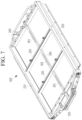
- FIG. 1 illustrates a schematic perspective view showing a battery pack according to an embodiment of the present invention
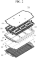
- FIG. 2 illustrates a schematic exploded perspective view showing the battery pack of FIG. 1 .
- the battery pack 700 includes: a base plate 100 configured to include a cooling passage in which a refrigerant for cooling a plurality of battery modules 500 circulates by contacting a first surface thereof with the battery modules 500; a lower cover 200 configured to cover a second surface of the base plate100; a frame portion 300 configured to be installed at an upper side of the first surface of the base plate 100, to accommodate a plurality of battery modules 500 therein, and to have a plurality of frames coupled to each other by a fastening member; and an upper cover 400 configured to cover an upper portion of the frame portion 300.
- the base plate 100 may be installed to support lower portions of the battery modules 500 accommodated inside the frame portion 300. That is, the base plate 100 may be installed below the frame portion 300 to enable battery module cooling while the first surface, which is an upper surface, supports the lower portions of the battery modules 500.
- a second surface, which is a lower surface, of the base plate 100, may be covered by a lower cover 200.
- This base plate 100 may include at least two plates, to be installed in a state in which edges are coupled to each other.
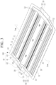
- FIG. 3 illustrates a schematic perspective view showing a base plate according to an embodiment of the present invention
- FIG. 4 illustrates a cross-sectional view taken along a line A-A of FIG. 3
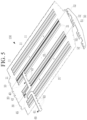
- FIG. 5 illustrates an exploded perspective view of main parts showing a state in which a refrigerant supply guide, a distribution supply guide, and a refrigerant discharge guide are separated from the base plate of FIG. 3
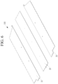
- FIG. 6 illustrates an exploded perspective view showing a state in which the base plate of FIG. 3 is separated into first to third cooling plates.
- the base plate 100 may include a first cooling plate 10 in which a first cooling passage 11 protrudes, a second cooling plate 20 in which a second cooling passage 21 protrudes, and a third cooling plate 30 in which a third cooling passage 31 protrudes.
- the first to third cooling plates 10, 20, and 30 may be welded together on a same plane in a state in which edges are in contact with each other.
- the first cooling plate 10 may constitute a portion of the base plate 100, and may be formed to have a plate shape, so as to contact and support the lower portions of the battery modules 500 on the first surface, which is the upper surface.
- the first cooling passage 11 for cooling the battery modules 500 may be formed on a second surface, which is a rear surface, of the first cooling plate 10.
- the first cooling passage 11, which protrudes from the second surface of the first cooling plate 10, may be formed to circulate a refrigerant supplied by a refrigerant supply guide 40 to be described later.
- the first cooling passage 11 may include a plurality of cooling passages formed on the second surface of the first cooling plate 10 along a longitudinal direction thereof, and in the present embodiment, four passages may be formed so that the refrigerant is movable therein.
- first cooling passage 11 is illustratively described as being formed as four passages, the present invention is not necessarily limited thereto, and an appropriate number of first cooling passages may protrude from the second surface corresponding to a length and width of the first cooling plate 10 such that a sufficient refrigerant for cooling the battery modules 500 is moved.
- a second cooling plate 20 may be coupled to a side surface of the first cooling plate 10.
- the second cooling plate 20 is formed with a similar length and width to those of the first cooling plate 10, and may be coupled with one edge in contact with one edge of the first cooling plate 10.
- first cooling plate 10 and the second cooling plate 20 may be welded in a state in which edges are in contact with each other.
- the first cooling plate 10 and the second cooling plate 20 may be connected to form an integrated bottom plate.
- the second cooling passage 21 for cooling the battery modules 500 may be formed on a second surface, which is a rear surface, of the second cooling plate 20.
- the second cooling passage 21 may include a plurality of second cooling passages 21 that protrude from the second surface of the second cooling plate 20, some may be connected to the refrigerant supply guide 40, and the others may be connected to the refrigerant discharge guide 60.
- the second cooling passage 21 may be formed such that a refrigerant is introduced and circulated through the refrigerant supply guide 40 and the refrigerant that has been circulated is discharged to the outside through the refrigerant discharge guide 60.
- the second cooling passage 21 may include a plurality of cooling passages formed on the second surface of the second cooling plate 20 along a longitudinal direction thereof, and in the present embodiment, four passages may be formed so that the refrigerant is movable therein.
- the second cooling passage 21 is illustratively described as being formed as four passages, the present invention is not necessarily limited thereto, and an appropriate number of second cooling passages may protrude from the second surface corresponding to a length and width of the second cooling plate 20 such that a sufficient refrigerant for cooling the battery modules 500 is moved.
- a third cooling plate 30 may be coupled to a side surface of the second cooling plate 20.
- the third cooling plate 30 is formed with a similar length and width to those of the second cooling plate 20, and may be coupled with one edge in contact with one edge of the second cooling plate 20.
- the second cooling plate 20 and the third cooling plate 30 may be welded in a state in which edges are in contact with each other.
- the second cooling plate 20 and the third cooling plate 30 may be connected to form an integrated bottom plate.
- first cooling plate 10 the second cooling plate 20, and the third cooling plate 30 are welded together with edges in contact with each other to form the base plate 100 forming an integrated bottom plate.
- the refrigerant supply guide 40, the distribution supply guide 50, and the refrigerant discharge guide 60 may be installed on the base plate 100, and thus a refrigerant may be installed to circulate through the first to third cooling passages 11, 21, and 31.
- the refrigerant supply guide 40 may include a supply guide body 41 covering the first cooling plate 10 and portions of the second cooling plate 20, and an inlet protrusion 42 and a supply protrusion 43 protruding from the supply guide body 41.
- the supply guide body 41 may be installed to extend in a width direction of the first cooling plate 10, so as to cover portions of the first cooling plate 10 and the second cooling plate 20 and to allow a refrigerant to move therein.
- the inlet protrusion 42 may protrude from one side of the supply guide body 41 so that the refrigerant flows into the supply guide body 41.
- the inlet protrusion 42 may protrude from a side surface of the supply guide body 41 so as to be connected to a predetermined refrigerant supply source and to receive the refrigerant.
- the supply protrusion 43 may protrude from a second side surface of the supply guide body 41 to supply a refrigerant to the first cooling passage 11 and portions of the second cooling passage 21.
- a plurality of supply protrusions 43 may protrude from the side of the supply guide body 41 to be connected to the first cooling passage 11 and the second cooling passage 21.
- the refrigerant supplied by the refrigerant supply guide 40 configured as described above may be supplied to the first cooling passage 11 and portions of the second cooling passage 21 to move toward the distribution supply guide 50.
- the distribution supply guide 50 may be installed in the base plate 100 such that the refrigerant supplied through the refrigerant supply guide 40 circulates in the first to third cooling passages 11, 21, and 31.
- the distribution supply guide 50 may extend in the width direction of the base plate 100, and may include, therein, a distribution guide body 51 through which the refrigerant is moved, and a plurality of distribution protrusions 52 protruding from a side surface of the distribution guide body 51 and connected to the first cooling passage 11, the second cooling passage 21, and the third cooling passage 31.
- the distribution guide body 51 may extend in a width direction of the base plate 100, and may be installed at an edge of the second surface of the base plate 100 so as to be connectable to each of the first to third cooling passages 11, 21, and 31.
- the distribution protrusions 52 which protrude from the side surface of the distribution guide body 51, may protrude from the side of the distribution guide body 51 in a same number as a number of first to third cooling passages, so as to be connected to each of the first to third cooling channels 11, 21, and 31.
- the distribution supply guide 50 may be connected to the refrigerant supply guide 40 by the first cooling passage 11 and portions of the second cooling passage 21, and thus may be installed to receive the refrigerant and to distribute and supply the refrigerant in a direction of the refrigerant discharge guide 60.
- the distribution supply guide 50 may be connected to the refrigerant supply guide 40 by the first cooling passage 11 and portions of the second cooling passage 21 to receive the refrigerant, and the supplied refrigerant may be distributed to the refrigerant discharge guide 60 connected to remaining portions of the second cooling passage 21 and the third cooling passage 31.
- the refrigerant circulates between the first to third cooling passages 11, 21, and 31 between the refrigerant supply guide 40, the distribution supply guide 50, and the refrigerant discharge guide 60 on the second surface, which is the lower surface of the base plate 100, and thus effective cooling of the battery modules 500 is possible.
- the refrigerant discharge guide 60 may extend in a width direction of the third cooling plate 30 so that a portion thereof may extend to cover a portion of the second surface of the second cooling plate 20.
- the refrigerant discharge guide 60 may discharge and guide the refrigerant flowing through the third cooling passage 31 and portions of the second cooling passage 21 to the outside.
- the refrigerant discharge guide 60 may extend in the width direction of the third cooling plate 30 such that a portion thereof covers portions of the second surface of the second cooling plate 20, and may include, therein, a discharge guide body 61 through which the refrigerant is moved, a connection protrusion 63 protruding from a first side of the discharge guide body 61 and connected to the portions of the second cooling passage 21 and the third cooling passage 31 through which the refrigerant flows, and a discharge protrusion 65 protruding from a second side of the discharge guide body 61 to discharge the refrigerant to the outside.
- the discharge guide body 61 may extend in the width direction of the third cooling plate 30, and may be installed to cover a portion of the second cooling plate 20 together. That is, the discharge guide body 61 may be installed to allow a portion thereof to further extend to cover a portion of the second cooling plate 20 together while covering the width direction of the third cooling plate 30.
- connection protrusion 63 may protrude such that a first side of the discharge guide body 61 protrudes and is connected to a portion of the second cooling passage 21 and the third cooling passage 31 to allow the refrigerant to flow therein, and may be connected such that the refrigerant discharged from the distribution supply guide 50 is discharged to the outside.
- the discharge protrusion 65 may protrude from a second side of the discharge guide body 61 so as to discharge the refrigerant to the outside.
- FIG. 7 illustrates a schematic perspective view showing a frame portion according to an embodiment of the present invention
- FIG. 8 illustrates an exploded perspective view showing the frame portion of FIG. 7 .
- the frame portion 300 may include a first side frame 210 and a second side frame 220, a first end frame 230 and a second end frame 240 connecting the first side frame 210 and the second side frame 220 to each other, and a first reinforcement bar 250 and a second reinforcement bar 260.
- the first side frame 210 may be coupled to a first edge of the base plate 100, and may be installed to support a first side of the battery modules 500.
- the second side frame 220 may be coupled to a second edge of the base plate 100, and may be installed to support a second side of the battery modules 500.
- the first end frame 230 may be installed to connect between first ends of each of the first side frame 210 and the second side frame 220.
- a first end of the first end frame 230 may be connected to a second end of the first side frame 210 by a fastening member 211, and a second end thereof may be connected to a first end of the second side frame 220 by the fastening member 211.
- the second end frame 240 may be installed to connect between second ends of each of the first side frame 210 and the second side frame 220.
- a first end of the second end frame 240 may be connected to a second end of the first side frame 210 by the fastening member 211, and a second end thereof may be connected to a second end of the second side frame 220 by the fastening member 211.
- a first or second reinforcement bar 250 or 260 may be connected at an inside where the first or second side frame 210 or 220 and the first or second end frame 230 or 240 are connected to each other by the fastening member 211.
- the first and second reinforcement bars 250 and 260 may be installed in a state of crossing each other, and may divide the inside of the frame portion 300 into a plurality of spaces, so that the battery modules may be accommodated in a properly arranged state.
- the first reinforcement bar 250 may have a first end connected to a side surface of the first side frame 210 by a fastening member 211 and a second end connected to a side surface of the second side frame 220 by a fastening member 211.
- a plurality of first reinforcement bars 250 may be installed to be spaced apart from each other at equal intervals between the first side frame 210 and the second side frame 220.
- the second reinforcement bar 260 may have a first end connected to a side surface of the first end frame 230 by the fastening member 211 and a second end connected to a side surface of the second end frame 240 by the fastening member 211.
- the second reinforcement bar 260 may be installed in a state of crossing the first reinforcement bar 250.
- a coupling groove 251 may be formed in the first reinforcement bar 250 at a position intersecting the second reinforcement bar 260.
- first reinforcement bar 250 and the second reinforcement bar 260 may be installed in a state of crossing each other to form a plurality of partitioned spaces such that the battery modules 500 are inserted into the frame portion 300.
- An insertion groove 261 for inserting a cell supervising circuit (CSC) may be formed in the second reinforcement bar 260.
- a plurality of insertion grooves 261 are formed in the second reinforcement bar 260, so that a plurality of cell supervising circuit boards may be inserted and fixed.
- spaces between a plurality of frames constituting the frame portion 300 may be sealed by a sealing member 270 (see FIG. 9 ).
- the sealing member 270 may be installed to enable stable sealing to prevent inflow of external foreign substances at the assembly position in a process of assembling the frames constituting the frame portion 300 using the fastening member 211.
- FIG. 9 illustrates a exploded perspective view of main parts showing a state in which a sealing member is installed inside a frame portion according to an embodiment of the present invention
- FIG. 10 illustrates main parts schematically showing a bent portion is formed at an upper portion of a first sealer of the sealing member of FIG. 9 to be fixed to an upper cover by an adhesive
- FIG. 11 illustrates a exploded perspective view of main parts showing a state in which an adhesive groove is formed on a lower surface of a frame portion and an adhesive is applied to the adhesive groove according to an embodiment of the present invention.
- the sealing member 270 may include a first sealer 272 inserted into the inlet groove 271 formed on a surface between the plurality of frames, and a second sealer 274 inserted into a fastening hole 273 formed in the frames such that the fastening member is coupled thereto.
- the inlet groove 271 may be formed on any one surface of the frames facing each other, and may be formed at one edge of cross-sections of the frames.
- the inlet groove 271 may be formed with a long length in the vertical direction at an adjacent position where a fastening hole 273 is formed at an edge of one end of the frames.
- a first sealer 272 may be inserted into the inlet groove 271.
- the first sealer 272 may be formed with a long straight length corresponding to a length of the inlet groove 271, and may be inserted to seal between the frames constituting the frame portion 300.
- the first sealer 272 may be made of a rubber material, and a portion of the first sealer 272 may protrude out of the inlet groove 271 to contact the surface of the frame in the state of being inserted into the inlet groove 271, and may seal between the frames.
- a bent portion 272a may be formed at an upper portion of the first sealer 272 to be in contact with an upper surface of the frames.
- bent portion 272a may be bent such that the frame comes into contact with the upper surface in a state where the first sealer 272 is inserted into the inlet groove 271, and may be contact-fixed to an inner surface of the upper cover 400.
- the upper cover 400 may be fixed with an inner surface in contact with the surface of the bent portion 272a in a process of being fixed to cover an upper portion of the frame portion 300.
- An adhesive may be applied to the inner surface of the upper cover 400 at a position in contact with the bent portion 272a, and thus stable fixation of the upper cover 400 is possible.
- the second sealer 274 may have a through hole through which the fastening member 211 extends, to be inserted into the fastening hole 273 at a position between the frames.
- the second sealer 274 may be formed to have a ring shape with a through hole such that the fastening member 211 extends through the through hole to be fastened to the frame.
- a number of second sealers 274 corresponding to a number of fastening members 211 may be inserted into positions where the fastening members 211 are fastened.
- the second sealer 274 is made of the same rubber material as that of the first sealer 272, and can be inserted at a position where the fastening member 211 is fastened so that a stable sealing action is possible so that foreign materials do not inflow.
- an adhesive groove 275 may be formed on a lower surface of the frame portion 300.
- the adhesive groove 275 may be formed on surfaces of the first and second end frames 230 and 240, the first and second reinforcement bars 250 and 260, and the first and second side frames 210 and 220 constituting the frame portion 300.
- An adhesive 276 may be applied to the adhesive groove 275.
- a portion of the adhesive 276 may protrude out of the adhesive groove 275 in a state of being inserted into the adhesive groove 275, and thus may further provide a fixing force to enable more stable coupling during a coupling process of the base plate 100. That is, the base plate 100 may be more stably fixed to the frame portion 300 by the fastening member 211 and the adhesive 276.
- the battery pack 100 of the present embodiment may be assembled using a fastening member such as a bolt member or a screw member, and a sealing member may be inserted into the assembly position, and thus robust assembly and stable assembly without inflow of foreign substances are possible.
- a fastening member such as a bolt member or a screw member
- the cooling line may be installed in an integrated state on the base plate on which a plurality of battery modules are seated, and thus stable cooling of the battery modules may be possible, thereby improving the stability more.
- all of the base plate 100, the frame portion 300, and the upper cover 400 may be formed of an aluminium material and assembled using a fastening member 211, and thus it is easy to disassemble and assemble, so free design change is possible, and it is possible to take action quickly in response to errors.
- the frame portion 300 may be partitioned into a plurality of partition spaces by the first and second side frames 210 and 220, the first and second end frames 230 and 240, and the first and second reinforcement bars 250 and 260, and the battery modules 500 may be inserted into the partition spaces.
- FIG. 12 illustrates a schematic perspective view showing a battery module according to a first embodiment of the present invention
- FIG. 13 illustrates an exploded perspective view showing a state in which an upper plate of the battery module of FIG. 12 is separated
- FIG. 14 illustrates a perspective view showing a state in which an upper plate of the battery module of FIG. 12 is removed
- FIG. 15 illustrates a schematic exploded perspective view showing the battery module of FIG. 14
- FIG. 16 illustrates a schematic perspective view showing coupling of an insulating plate and a first end plate according to the first embodiment of the present invention
- FIG. 17 illustrates a schematic perspective view showing the insulating plate of FIG. 16
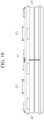
- FIG. 18 illustrates a state in which a gas tunnel portion is formed in the battery module according to the first embodiment of the present invention.
- the battery modules 500 may include a first side plate 420 supporting a first side of a plurality of battery cells 410, a second side plate 430 supporting a second side of the battery cells 410, a first end plate 440 having opposite ends connected to a first end of each of the first side plate 420 and the second side plate 430 by the fastening member 211, a second end plate 450 having opposite ends connected to a second end of each of the first side plate 420 and the second side plate 430 by the fastening member 211, an insulating plate 460 coated with an adhesive 461 fixed to side surfaces of the battery cells 410, at opposite side surfaces having a first end connected to a side surface of the first end plate 440, and a second end connected to a side surface of the second end plate 450, and a upper plate 470 covering a upper portion of the battery cells 410.
- the first side plate 420 may be installed to support a first side of the battery cells 410.
- the first side plate 420 may be supported in a state of being in surface contact with a side surface of the battery cells 410.
- a surface of the first side plate 420 in surface contact with the battery cells 410 may be coated with insulation.
- the battery cells 410 may be stably accommodated inside the frame portion 300 in an electrically insulated state.
- the second side plate 430 may be installed to support a second side of the battery cells 410.
- the second side plate 430 may be supported in a state of being in surface contact with a side surface of the battery cells 410.
- a surface of the second side plate 430 in surface contact with the battery cell 410 may be coated with insulation.
- the battery modules 500 may be installed in an electrically insulated state between the first side plate 420 and the second side plate 430.
- first end plate 440 may be installed to connect first ends of the first side plate 420 and the second side plate 430 to each other.
- a first end of the first end plate 440 may be connected to a first end of the first side plate 420 by a fastening member 211, and a second end thereof may be connected to a first end of the second side plate 430 by the fastening member 211.
- the second end plate 450 may be installed to connect second ends of the first side plate 420 and the second side plate 430 to each other.
- a first end of the second end plate 450 may be connected to a second end of the first side plate 420 by a fastening member 211, and a second end thereof may be connected to a second end of the second side plate 430 by the fastening member 211.
- a first mount protrusion 441 fixed to the upper cover 400 by a fastening member may protrude from an upper edge of the first end plate 440.
- the first mount protrusion 441 may protrude to a side surface of the first end plate 440 in a state where a fastening hole to which the fastening member 211 is coupled is formed, and a first side of the upper cover 400 may be stably coupled to an upper side of the frame portion 300.
- a second mount protrusion 451 fixed to the upper cover 400 by a fastening member may protrude from an upper edge of the second end plate 450.
- the second mount protrusion 451 may protrude to a side surface of the second end plate 450 in a state where a fastening hole to which the fastening member 211 is coupled is formed, and a second side of the upper cover 400 may be stably coupled to an upper side of the frame portion 300.
- the insulating plate 460 may be connected in an inside where the first and second side plates 420 and 430 and the first and second end plates 440 and 450 connected to each other by the fastening member 211.
- the insulating plate 460 may have a first end connected to a side surface of the first end plate 440 and a second end connected to a side surface of the second end plate 450.
- a first coupling hole 442 to which a first end of the insulating plate 460 is fixed may be formed on a side surface of the first end plate 440.
- a second coupling hole 452 to which a second end of the insulation plate 460 is fixed may be formed on a side surface of the second end plate 450.
- the insulating plate 460 may have a first end from which a first coupling protrusion 462 that is inserted and fixed into a first coupling hole 442 protrudes, and a second end from which a second coupling protrusion 464 that is inserted and fixed into the second coupling hole 452 protrudes.
- An adhesive 461 fixed to a side surface of the battery cells 410 may be applied to opposite surfaces of the insulating plate 460.
- the adhesive 461 is applied to each of the opposite side surfaces of the insulating plate 460, and thus a fixing force may be provided so that the battery modules 500 accommodated inside the frame portion 300 are stably positioned on a side surface of the insulating plate 460.
- a plurality of bus bars 471 installed to be electrically connected to terminals of the battery cells 410 may be installed in an upper plate 470.
- the bus bars 471 may be installed on the upper plate 470 in a state of being disposed in the first direction to be electrically connected to the terminals of the battery cells 410 positioned in the first direction (z-axis direction) inside the frame portion 300.
- a gas tunnel portion 472 may be installed on a side surface of the bus bar 471.
- the gas tunnel portion 472 may be installed on the upper plate 470 to discharge gas generated by a cell event caused by an abnormal operation of the battery modules 500 to the outside.
- the gas tunnel portion 472 is formed with a long length along a longitudinal direction of the upper plate 470 between a plurality of bus bars 471, and in the present embodiment, installation of a pair in the upper plate 470 with the bus bars 471 therebetween will be described as an example.
- the gas tunnel portion 472 is installed in the upper plate 470, and thus the gas may be smoothly discharged to the outside in an abnormal operating state of the battery modules 500 to prevent an abnormal explosion or the like from occurring.
- the battery modules 500 of the present embodiment are assembled to be disassemblable and assemblable by fastening of a fastening member replacing a welding process in an assembly process, and thus a structure of the battery modules may be simplified and a design thereof may be easily changed.
- a cooling circuit is formed outside the base plate supporting the battery module, and thus it is possible to prevent an electrical flow path from being generated during an operation of the battery modules.
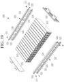
- FIG. 19 illustrates a schematic exploded perspective view showing a battery module according to a second embodiment of the present invention
- FIG. 20 illustrates a schematic perspective view showing a first side portion of FIG. 19
- FIG. 21 illustrates a schematic side view showing a state in which an insert bar of the battery module of FIG. 19 is installed.
- the battery module 600 includes a first side portion 520 supporting a first side of the battery cells 410, a second side portion 530 supporting a second side of the battery cells 410, a first end portion 540 having opposite ends connected to a first end of each of the first side portion 520 and the second side portion 530 by the fastening member 211, a second end portion 550 having opposite ends connected to a second end of each of the first side portion 520 and the second side portion 530 by the fastening member 211, and an insert bar 522 inserted into the first side portion 520 and the second side portion 530.
- the first side portion 520 may be coupled to a first edge of the base plate 100, and may be installed to support a first side of the battery cells 410.
- the first side portion 520 may be supported in a state of being in surface contact with a side surface of the battery cells 410.
- the first side portion 520 may be formed of a plastic material to support a first side of the battery cells 410 in an insulated state.
- the first side portion 520 may include a first plate 521 having a plurality of through holes 523 into which terminals of the battery cells 410 are inserted, and a first insert portion 524 that protrudes from a side surface of a first plate 521 and has an insertion hole into which an insert bar 522 is inserted.
- the first plate 521 may be supported in surface contact with a side surface of the battery cells 410, and may be formed of a plastic material to support a first side of the battery cells 410 in an insulated state.
- the first plate 521 may be formed with a plurality of through holes 523 along a longitudinal direction, and terminals of the battery cells 410 may be installed to be inserted into the through holes 523. To this end, the battery cells 410 may be positioned such that terminals face the through hole 523 of the first plate 521.
- a first insert portion 524 into which an insert bar 522 for reinforcement is inserted may protrude from the first plate 521.
- the first insert portion 524 may be formed to protrude from the side surface of the first plate 521 in a longitudinal direction, and an insertion hole into which the insert bar 522 is inserted may be formed.
- the insert bar 522 is formed to a length corresponding to a length of the first plate 521 to be inserted into the first insert portion 524, and may be formed of a metal material to ensure durability.
- the second side portion 530 may be coupled to a second edge of the base plate 100, and may be installed to support a second side of the battery cells 410.
- the second side portion 530 may be supported in a state of being in surface contact with a side surface of the battery cells 410.
- the second side portion 530 may be formed of a plastic material to support a second side of the battery cells 410 in an insulated state.
- a second insert portion 534 into which an insert bar 522 for reinforcement is inserted may protrude from the second plate 531.
- the second insert portion 534 may be formed to protrude from the side surface of the second plate 531 in a longitudinal direction, and an insertion hole into which the insert bar 522 is inserted may be formed.
- the insert bar 522 is formed to a length corresponding to a length of the second plate 531 to be inserted into the second insert portion 534, and may be formed of a metal material to ensure durability.
- a bus bar 526 electrically connected to terminals of the battery cells 410 may be installed in each of the first plate 521 and the second plate 531.
- each of the first plate 521 and the second plate 531 may be coated with an adhesive 560 at a position in surface contact with the battery cells 410.
- the adhesive 560 may be applied to a surface of each of the first plate 521 and the second plate 531 in a longitudinal direction, and thus a fixing force of each of the first plate 521 and the second plate 531 installed on side surfaces of the battery cells 410 may be improved.
Landscapes
- Chemical & Material Sciences (AREA)
- Chemical Kinetics & Catalysis (AREA)
- Electrochemistry (AREA)
- General Chemical & Material Sciences (AREA)
- Engineering & Computer Science (AREA)
- Manufacturing & Machinery (AREA)
- Aviation & Aerospace Engineering (AREA)
- Battery Mounting, Suspending (AREA)
Abstract
Description
- The present invention relates to a battery pack capable of simplifying a structure and preventing occurrence of an electrical error.
- Secondary batteries are widely used in mobile devices, auxiliary power devices, and the like.
- In addition, the secondary batteries attracting attention as a main power source for electric vehicles, hybrid electric vehicles, plug-in hybrid electric vehicles, and the like, suggested as an alternative to solve various problems such as air pollution of conventional gasoline vehicles or diesel vehicles.
- However, a battery module in which a plurality of battery cells are stacked and electrically connected in series and parallel is used for electric vehicles, etc., due to a need for a high-output and large-capacity battery.
- In the battery module, a plurality of battery cells are stacked, and terminals exposed at opposite ends of each of the battery cells are electrically connected to provide high voltage.
- For such a battery module, pack housings of various methods and sizes suitable for a shape and pack capacity are being manufactured, and in many ways, such as scalability, serviceability, and recycling, a current pack has its limitations.
- That is, a conventional battery module has a problem in that it is not easy to change a design depending on energy capacity to be supplied, and a manufacturing efficiency is deteriorated.
- The above information disclosed in this Background section is only for enhancement of understanding of the background of the invention, and therefore, it may contain information that does not form the prior art that is already known to a person of ordinary skill in the art.
- An embodiment of the present invention has been made in an effort to provide a battery pack that simplifies a structure of a battery module by eliminating a welding process, and prevents a risk of an electrical error by forming a cooling circuit at the outside.
- An embodiment of the present invention provides a battery pack including: a base plate configured to include a cooling passage through which a refrigerant for cooling a plurality of battery modules is circulated by contacting the battery modules with a first surface, a lower cover configured to cover a second surface of the base plate, a frame portion installed on an upper side of a first surface of the base plate to accommodate the battery modules therein and to couple a plurality of frames to each other by a fastening member (i.e. and including a plurality of frames coupled to each other by a fastening member), and an upper cover covering an upper portion of the frame portion.
- Spaces between the frames constituting the frame portion may be sealed by a sealing member.
- The cooling passage may be formed on a second surface that is opposite to the first surface of the base plate.
- The base plate may include at least two cooling plates having edges that are welded to each other.
- The base plate may include: a first cooling plate configured to contact the battery modules on a first surface and to protrude a first cooling passage on a second surface; a second cooling plate to have a first edge coupled to a first edge of the first cooling plate, a first surface contacting the battery modules, and a second surface from which a second cooling passage protrudes; and a third cooling plate to have a first edge coupled to a second edge of the second cooling plate, a first surface contacting the battery modules, and a second surface from which a third cooling passage protrudes.
- The first to third cooling passages may be formed as a plurality in each of the first to third cooling plates.
- A refrigerant supply guide may be installed at a first side of the second surface of the base plate to guide supply of a refrigerant to the first cooling passage and portions of the second cooling passage.
- The refrigerant supply guide may be installed to supply the refrigerant to the first cooling passage of the first cooling plate and portions of the second cooling passage of the second cooling plate.
- The refrigerant supply guide may extend in a width direction of the first cooling plate such that a portion thereof covers a portion of the second surface of the second cooling plate to supply the refrigerant to the first cooling passage and portions of the second cooling passage.
- The refrigerant supply guide may include: a supply guide body configured to extend in the width direction of the first cooling plate, to cover the first cooling plate and portions of the second cooling plate together, and to move a refrigerant therein; an inlet protrusion configured to protrude from a first side of the supply guide body and into which the refrigerant flows; and a plurality of supply protrusions configured to protrude from a second side of the supply guide body and to supply a refrigerant to the first cooling passage and portions of the second cooling passage.
- A distribution supply guide configured to distribute the refrigerant supplied by the refrigerant supply guide to circulate may be installed at a second side of the second surface of the base plate.
- The distribution supply guide may include: a distribution guide body configured to extend in a width direction of the base plate from the second side of the second surface of the base plate and to move the refrigerant therein; and a plurality of distribution protrusions configured to protrude from a side surface of the distribution guide body and to be connected to the first cooling passage, the second cooling passage, and the third cooling passage.
- A refrigerant discharge guide connected to some of the second cooling passages of the second cooling plate and the third cooling passage of the third cooling plate may be installed to guide discharge of the refrigerant to the outside on the second surface of the base plate.
- The refrigerant discharge guide may extend in a width direction of the third cooling plate such that a portion thereof covers a portion of the second surface of the second cooling plate to discharge and guide the refrigerant flowing through the third cooling passage and some of the second cooling passages to the outside.
- The refrigerant discharge guide may include: a discharge guide body configured to extend in a width direction of the third cooling plate such that a portion thereof covers a portion of the second surface of the second cooling plate, and to move the refrigerant therein; a connecting protrusion configured to protrude from a first side of the discharge guide body and connected to some of the second cooling passages and the third cooling passage to receive the refrigerant; and a discharge protrusion configured to protrude from a second side of the discharge guide body and to discharge the refrigerant to the outside.
- The sealing member may include: a first sealer inserted into an inlet groove formed on any one surface between the frames; and a second sealer inserted into a position of a fastening hole formed in the frame to allow the fastening member to be coupled thereto.
- The first sealer may contact a side surface of the frames by allowing a first side to be inserted into the inlet groove and a second side to partially protrude out of the inlet groove.
- The first sealer may have a linear shape inserted into the inlet groove.
- A bent portion that is bent to contact an upper surface of the frames may be formed at an upper end of the first sealer.
- The bent portion of the first sealer may be adhered to the upper cover by an adhesive member.
- The second sealer may have a through hole through which the fastening member extends, to be inserted into the fastening hole at a position between the frames.
- The second sealer may have a round shape inserted into the fastening hole.
- The frame portion may include: a first side frame coupled to a first edge of the base plate; a second side frame coupled to a second edge of the base plate; a first end frame configured to have opposite ends connected to a first end of each of the first side frame and the second side frame by a fastening member; a second end frame configured to have opposite ends connected to a second end of each of the first side frame and the second side frame by a fastening member; first reinforcement bar configured to have a first end connected to a side surface of the first side frame by a fastening member and a second end connected to a side surface of the second side frame by a fastening member; and second reinforcement bar configured to have a first end connected to a side surface of the first end frame by a fastening member and a second end connected to a side surface of the second end frame by a fastening member, and installed in a state of crossing the first reinforcement bars.
- An adhesive groove may be formed on a lower surface of the frame portion, and an adhesive for fixing the base plate may be applied to the adhesive groove.
- The battery modules each may include: a first side plate configured to support a first side surface of a plurality of battery cells; a second side plate configured to support a second side surface of the battery cells; a first end plate configured to have opposite ends connected to a first end of each of the first side plate and the second side plate by a fastening member; a second end plate configured to have opposite ends connected to a second end of each of the first side plate and the second side plate by a fastening member; an insulating plate configured to have a first end connected to a side surface of the first end plate and a second end connected to a side surface of the second end plate and coated with an adhesive fixed to side surfaces of the battery cells at opposite side surfaces; and an upper plate configured to cover an upper portion of the battery cells.
- A first coupling hole to which a first end of the insulating plate is fixed may be formed on a side surface of the first end plate.
- A second coupling hole to which a second end of the insulating plate is fixed may be formed on a side surface of the second end plate.
- The insulating plate may have a first end from which a first coupling protrusion that is inserted and fixed into a first coupling hole protrudes, and a second end from which a second coupling protrusion that is inserted and fixed into the second coupling hole protrudes.
- A surface of each of the first side plate and the second side plate in contact with the battery cell may be insulatingly coated.
- A first mount protrusion fixed to the upper cover by a fastening member may protrude from an edge of the first end plate.
- A second mount protrusion fixed to the upper cover by a fastening member may protrude from an edge of the second end plate.
- The upper plate may include: a plurality of bus bars installed to be electrically connected to terminals of the battery cells; and a gas tunnel portion formed between the bus bars in a longitudinal direction of the upper cover.
- The battery modules each may include: a first side portion configured to support a first side surface of a plurality of battery cells; a second side portion configured to support a second side surface of the battery cells; a first end portion configured to have opposite ends connected to a first end of each of the first side portion and the second side portion by a fastening member; a second end portion configured to have opposite ends connected to a second end of each of the first side portion and the second side portion by a fastening member; and an insert bar inserted into the first side portion and the second side portion.
- Terminals of the battery cells may be positioned to face a direction of the first side portion and the second side portion.
- The first side portion and the second side portion may be made of a plastic material.
- The first side portion may include: a first plate configured to have a plurality of through holes into which terminals of the battery cells are inserted; and a first insert portion configured to protrude from a side surface of the first plate and to have an insertion hole into which the insert bar is inserted that is formed therein.
- The first insert portion may be formed at a first edge position and a second edge position with the through hole provided therebetween in the first plate.
- A bus bar electrically connected to the terminal extending through the through hole may be installed in the first side portion.
- An adhesive may be applied between the first plate and the battery cells.
- The second side portion may include: a second plate configured to have a plurality of through holes into which terminals of the battery cells are inserted; and a second insert portion configured to protrude from a side surface of the second plate and to have an insertion hole into which the insert bar is inserted that is formed therein.
- The second insert portion may be formed at a first edge position and a second edge position with the through hole provided therebetween in the second plate.
- A bus bar electrically connected to the terminal extending through the through hole may be installed in the second side portion.
- An adhesive may be applied between the second plate and the battery cells.
- At least some of the above and other features of the invention are set out in the claims.
- According to an embodiment of the present invention, the battery modules may be assembled to be disassemblable and assemblable by fastening of a fastening member replacing a welding process in an assembly process, and thus a structure of the battery modules may be simplified and a design thereof may be easily changed.
- According to an embodiment of the present invention, a cooling circuit is formed in an external portion of the base plate supporting the battery module, and thus it is possible to prevent occurrence of an electrical error during an operation of the battery modules.
-
-
FIG. 1 illustrates a schematic perspective view showing a battery pack according to an embodiment of the present invention. -
FIG. 2 illustrates a schematic exploded perspective view showing the battery pack ofFIG. 1 . -
FIG. 3 illustrates a schematic perspective view showing a base plate according to an embodiment of the present invention. -
FIG. 4 illustrates a cross-sectional view taken along a line A-A ofFIG. 3 . -
FIG. 5 illustrates an exploded perspective view of main parts showing a state in which a refrigerant supply guide, a distribution supply guide, and a refrigerant discharge guide are separated from the base plate ofFIG. 3 . -
FIG. 6 illustrates an exploded perspective view showing a state in which the base plate ofFIG. 3 is separated into first to third cooling plates. -
FIG. 7 illustrates a schematic perspective view showing a frame portion according to an embodiment of the present invention. -
FIG. 8 illustrates an exploded perspective view showing the frame portion ofFIG. 7 . -
FIG. 9 illustrates an exploded perspective view of main parts showing a state in which a sealing member is installed inside a frame portion according to an embodiment of the present invention. -
FIG. 10 illustrates main parts schematically showing a bent portion that is formed at an upper portion of a first sealer of the sealing member ofFIG. 9 to be fixed to an upper cover by an adhesive. -
FIG. 11 illustrates an exploded perspective view of main parts showing a state in which an adhesive groove is formed on a lower surface of a frame portion and an adhesive is applied to the adhesive groove according to an embodiment of the present invention. -
FIG. 12 illustrates a schematic perspective view showing a battery module according to a first embodiment of the present invention. -
FIG. 13 illustrates an exploded perspective view showing a state in which an upper plate of the battery module ofFIG. 12 is separated. -
FIG. 14 illustrates a perspective view showing a state in which an upper plate of the battery module ofFIG. 12 is removed. -
FIG. 15 illustrates a schematic exploded perspective view showing the battery module ofFIG. 14 . -
FIG. 16 illustrates a schematic perspective view showing coupling of an insulating plate and a first end plate according to the first embodiment of the present invention. -
FIG. 17 illustrates a schematic perspective view showing the insulating plate ofFIG. 16 . -
FIG. 18 illustrates a state in which a gas tunnel portion is formed in the battery module according to the first embodiment of the present invention. -
FIG. 19 illustrates a schematic exploded perspective view showing a battery module according to a second embodiment of the present invention. -
FIG. 20 illustrates a schematic perspective view showing a first side portion ofFIG. 19 . -
FIG. 21 illustrates a schematic side view showing a state in which an insert bar of the battery module ofFIG. 19 is installed. - Hereinafter, the present invention will be described more fully with reference to the accompanying drawings, in which embodiments of the invention are shown. As those skilled in the art would realize, the described embodiments may be modified in various different ways, all without departing from the scope of the present invention. The drawings and description are to be regarded as illustrative in nature and not restrictive. Like reference numerals designate like elements throughout the specification.
-
FIG. 1 illustrates a schematic perspective view showing a battery pack according to an embodiment of the present invention, andFIG. 2 illustrates a schematic exploded perspective view showing the battery pack ofFIG. 1 . - As illustrated in
FIG. 1 andFIG. 2 , according to a first embodiment of the present invention, thebattery pack 700 includes: abase plate 100 configured to include a cooling passage in which a refrigerant for cooling a plurality ofbattery modules 500 circulates by contacting a first surface thereof with thebattery modules 500; alower cover 200 configured to cover a second surface of the base plate100; aframe portion 300 configured to be installed at an upper side of the first surface of thebase plate 100, to accommodate a plurality ofbattery modules 500 therein, and to have a plurality of frames coupled to each other by a fastening member; and anupper cover 400 configured to cover an upper portion of theframe portion 300. - The
base plate 100 may be installed to support lower portions of thebattery modules 500 accommodated inside theframe portion 300. That is, thebase plate 100 may be installed below theframe portion 300 to enable battery module cooling while the first surface, which is an upper surface, supports the lower portions of thebattery modules 500. A second surface, which is a lower surface, of thebase plate 100, may be covered by alower cover 200. - This
base plate 100 may include at least two plates, to be installed in a state in which edges are coupled to each other. -
FIG. 3 illustrates a schematic perspective view showing a base plate according to an embodiment of the present invention,FIG. 4 illustrates a cross-sectional view taken along a line A-A ofFIG. 3 ,FIG. 5 illustrates an exploded perspective view of main parts showing a state in which a refrigerant supply guide, a distribution supply guide, and a refrigerant discharge guide are separated from the base plate ofFIG. 3 , andFIG. 6 illustrates an exploded perspective view showing a state in which the base plate ofFIG. 3 is separated into first to third cooling plates. - In more detail with reference to
FIG. 3 to FIG. 6 , thebase plate 100 may include afirst cooling plate 10 in which afirst cooling passage 11 protrudes, asecond cooling plate 20 in which asecond cooling passage 21 protrudes, and athird cooling plate 30 in which athird cooling passage 31 protrudes. The first tothird cooling plates - The
first cooling plate 10 may constitute a portion of thebase plate 100, and may be formed to have a plate shape, so as to contact and support the lower portions of thebattery modules 500 on the first surface, which is the upper surface. - The
first cooling passage 11 for cooling thebattery modules 500 may be formed on a second surface, which is a rear surface, of thefirst cooling plate 10. - The
first cooling passage 11, which protrudes from the second surface of thefirst cooling plate 10, may be formed to circulate a refrigerant supplied by arefrigerant supply guide 40 to be described later. - The
first cooling passage 11 may include a plurality of cooling passages formed on the second surface of thefirst cooling plate 10 along a longitudinal direction thereof, and in the present embodiment, four passages may be formed so that the refrigerant is movable therein. - Although the
first cooling passage 11 is illustratively described as being formed as four passages, the present invention is not necessarily limited thereto, and an appropriate number of first cooling passages may protrude from the second surface corresponding to a length and width of thefirst cooling plate 10 such that a sufficient refrigerant for cooling thebattery modules 500 is moved. - A
second cooling plate 20 may be coupled to a side surface of thefirst cooling plate 10. - The
second cooling plate 20 is formed with a similar length and width to those of thefirst cooling plate 10, and may be coupled with one edge in contact with one edge of thefirst cooling plate 10. - Herein, the
first cooling plate 10 and thesecond cooling plate 20 may be welded in a state in which edges are in contact with each other. Thus, thefirst cooling plate 10 and thesecond cooling plate 20 may be connected to form an integrated bottom plate. - The
second cooling passage 21 for cooling thebattery modules 500 may be formed on a second surface, which is a rear surface, of thesecond cooling plate 20. - The
second cooling passage 21 may include a plurality ofsecond cooling passages 21 that protrude from the second surface of thesecond cooling plate 20, some may be connected to therefrigerant supply guide 40, and the others may be connected to therefrigerant discharge guide 60. - That is, the
second cooling passage 21 may be formed such that a refrigerant is introduced and circulated through therefrigerant supply guide 40 and the refrigerant that has been circulated is discharged to the outside through therefrigerant discharge guide 60. - The
second cooling passage 21 may include a plurality of cooling passages formed on the second surface of thesecond cooling plate 20 along a longitudinal direction thereof, and in the present embodiment, four passages may be formed so that the refrigerant is movable therein. - Although the
second cooling passage 21 is illustratively described as being formed as four passages, the present invention is not necessarily limited thereto, and an appropriate number of second cooling passages may protrude from the second surface corresponding to a length and width of thesecond cooling plate 20 such that a sufficient refrigerant for cooling thebattery modules 500 is moved. - A
third cooling plate 30 may be coupled to a side surface of thesecond cooling plate 20. - The
third cooling plate 30 is formed with a similar length and width to those of thesecond cooling plate 20, and may be coupled with one edge in contact with one edge of thesecond cooling plate 20. - Herein, the
second cooling plate 20 and thethird cooling plate 30 may be welded in a state in which edges are in contact with each other. Thus, thesecond cooling plate 20 and thethird cooling plate 30 may be connected to form an integrated bottom plate. - That is, the
first cooling plate 10, thesecond cooling plate 20, and thethird cooling plate 30 are welded together with edges in contact with each other to form thebase plate 100 forming an integrated bottom plate. - Meanwhile, as described above, the
refrigerant supply guide 40, thedistribution supply guide 50, and therefrigerant discharge guide 60 may be installed on thebase plate 100, and thus a refrigerant may be installed to circulate through the first tothird cooling passages - The
refrigerant supply guide 40 may include asupply guide body 41 covering thefirst cooling plate 10 and portions of thesecond cooling plate 20, and aninlet protrusion 42 and asupply protrusion 43 protruding from thesupply guide body 41. - The
supply guide body 41 may be installed to extend in a width direction of thefirst cooling plate 10, so as to cover portions of thefirst cooling plate 10 and thesecond cooling plate 20 and to allow a refrigerant to move therein. - The
inlet protrusion 42 may protrude from one side of thesupply guide body 41 so that the refrigerant flows into thesupply guide body 41. - That is, the
inlet protrusion 42 may protrude from a side surface of thesupply guide body 41 so as to be connected to a predetermined refrigerant supply source and to receive the refrigerant. - The
supply protrusion 43 may protrude from a second side surface of thesupply guide body 41 to supply a refrigerant to thefirst cooling passage 11 and portions of thesecond cooling passage 21. A plurality ofsupply protrusions 43 may protrude from the side of thesupply guide body 41 to be connected to thefirst cooling passage 11 and thesecond cooling passage 21. - The refrigerant supplied by the
refrigerant supply guide 40 configured as described above may be supplied to thefirst cooling passage 11 and portions of thesecond cooling passage 21 to move toward thedistribution supply guide 50. - The
distribution supply guide 50 may be installed in thebase plate 100 such that the refrigerant supplied through therefrigerant supply guide 40 circulates in the first tothird cooling passages - More specifically, the
distribution supply guide 50 may extend in the width direction of thebase plate 100, and may include, therein, adistribution guide body 51 through which the refrigerant is moved, and a plurality ofdistribution protrusions 52 protruding from a side surface of thedistribution guide body 51 and connected to thefirst cooling passage 11, thesecond cooling passage 21, and thethird cooling passage 31. - The
distribution guide body 51 may extend in a width direction of thebase plate 100, and may be installed at an edge of the second surface of thebase plate 100 so as to be connectable to each of the first tothird cooling passages - The distribution protrusions 52, which protrude from the side surface of the
distribution guide body 51, may protrude from the side of thedistribution guide body 51 in a same number as a number of first to third cooling passages, so as to be connected to each of the first tothird cooling channels - As described above, the
distribution supply guide 50 may be connected to therefrigerant supply guide 40 by thefirst cooling passage 11 and portions of thesecond cooling passage 21, and thus may be installed to receive the refrigerant and to distribute and supply the refrigerant in a direction of therefrigerant discharge guide 60. - That is, the
distribution supply guide 50 may be connected to therefrigerant supply guide 40 by thefirst cooling passage 11 and portions of thesecond cooling passage 21 to receive the refrigerant, and the supplied refrigerant may be distributed to therefrigerant discharge guide 60 connected to remaining portions of thesecond cooling passage 21 and thethird cooling passage 31. - Accordingly, the refrigerant circulates between the first to
third cooling passages refrigerant supply guide 40, thedistribution supply guide 50, and therefrigerant discharge guide 60 on the second surface, which is the lower surface of thebase plate 100, and thus effective cooling of thebattery modules 500 is possible. - Meanwhile, the
refrigerant discharge guide 60 may extend in a width direction of thethird cooling plate 30 so that a portion thereof may extend to cover a portion of the second surface of thesecond cooling plate 20. - Accordingly, the
refrigerant discharge guide 60 may discharge and guide the refrigerant flowing through thethird cooling passage 31 and portions of thesecond cooling passage 21 to the outside. - More specifically, the
refrigerant discharge guide 60 may extend in the width direction of thethird cooling plate 30 such that a portion thereof covers portions of the second surface of thesecond cooling plate 20, and may include, therein, adischarge guide body 61 through which the refrigerant is moved, aconnection protrusion 63 protruding from a first side of thedischarge guide body 61 and connected to the portions of thesecond cooling passage 21 and thethird cooling passage 31 through which the refrigerant flows, and adischarge protrusion 65 protruding from a second side of thedischarge guide body 61 to discharge the refrigerant to the outside. - The
discharge guide body 61 may extend in the width direction of thethird cooling plate 30, and may be installed to cover a portion of thesecond cooling plate 20 together. That is, thedischarge guide body 61 may be installed to allow a portion thereof to further extend to cover a portion of thesecond cooling plate 20 together while covering the width direction of thethird cooling plate 30. - The
connection protrusion 63 may protrude such that a first side of thedischarge guide body 61 protrudes and is connected to a portion of thesecond cooling passage 21 and thethird cooling passage 31 to allow the refrigerant to flow therein, and may be connected such that the refrigerant discharged from thedistribution supply guide 50 is discharged to the outside. - The
discharge protrusion 65 may protrude from a second side of thedischarge guide body 61 so as to discharge the refrigerant to the outside. -
FIG. 7 illustrates a schematic perspective view showing a frame portion according to an embodiment of the present invention, andFIG. 8 illustrates an exploded perspective view showing the frame portion ofFIG. 7 . - As illustrated in
FIG. 7 andFIG. 8 , theframe portion 300 may include afirst side frame 210 and asecond side frame 220, afirst end frame 230 and asecond end frame 240 connecting thefirst side frame 210 and thesecond side frame 220 to each other, and afirst reinforcement bar 250 and asecond reinforcement bar 260. - The
first side frame 210 may be coupled to a first edge of thebase plate 100, and may be installed to support a first side of thebattery modules 500. - The
second side frame 220 may be coupled to a second edge of thebase plate 100, and may be installed to support a second side of thebattery modules 500. - The
first end frame 230 may be installed to connect between first ends of each of thefirst side frame 210 and thesecond side frame 220. - That is, a first end of the
first end frame 230 may be connected to a second end of thefirst side frame 210 by afastening member 211, and a second end thereof may be connected to a first end of thesecond side frame 220 by thefastening member 211. - The
second end frame 240 may be installed to connect between second ends of each of thefirst side frame 210 and thesecond side frame 220. - That is, a first end of the
second end frame 240 may be connected to a second end of thefirst side frame 210 by thefastening member 211, and a second end thereof may be connected to a second end of thesecond side frame 220 by thefastening member 211. - A first or
second reinforcement bar second side frame second end frame fastening member 211. - The first and second reinforcement bars 250 and 260 may be installed in a state of crossing each other, and may divide the inside of the
frame portion 300 into a plurality of spaces, so that the battery modules may be accommodated in a properly arranged state. - The
first reinforcement bar 250 may have a first end connected to a side surface of thefirst side frame 210 by afastening member 211 and a second end connected to a side surface of thesecond side frame 220 by afastening member 211. - A plurality of first reinforcement bars 250 may be installed to be spaced apart from each other at equal intervals between the
first side frame 210 and thesecond side frame 220. - The
second reinforcement bar 260 may have a first end connected to a side surface of thefirst end frame 230 by thefastening member 211 and a second end connected to a side surface of thesecond end frame 240 by thefastening member 211. - The
second reinforcement bar 260 may be installed in a state of crossing thefirst reinforcement bar 250. To this end, acoupling groove 251 may be formed in thefirst reinforcement bar 250 at a position intersecting thesecond reinforcement bar 260. - Accordingly, the
first reinforcement bar 250 and thesecond reinforcement bar 260 may be installed in a state of crossing each other to form a plurality of partitioned spaces such that thebattery modules 500 are inserted into theframe portion 300. - An
insertion groove 261 for inserting a cell supervising circuit (CSC) may be formed in thesecond reinforcement bar 260. A plurality ofinsertion grooves 261 are formed in thesecond reinforcement bar 260, so that a plurality of cell supervising circuit boards may be inserted and fixed. - Meanwhile, spaces between a plurality of frames constituting the
frame portion 300 may be sealed by a sealing member 270 (seeFIG. 9 ). - The sealing
member 270 may be installed to enable stable sealing to prevent inflow of external foreign substances at the assembly position in a process of assembling the frames constituting theframe portion 300 using thefastening member 211. -
FIG. 9 illustrates a exploded perspective view of main parts showing a state in which a sealing member is installed inside a frame portion according to an embodiment of the present invention,FIG. 10 illustrates main parts schematically showing a bent portion is formed at an upper portion of a first sealer of the sealing member ofFIG. 9 to be fixed to an upper cover by an adhesive, andFIG. 11 illustrates a exploded perspective view of main parts showing a state in which an adhesive groove is formed on a lower surface of a frame portion and an adhesive is applied to the adhesive groove according to an embodiment of the present invention. - In more detail with reference to
FIG. 9 to FIG. 11 , the sealingmember 270 may include afirst sealer 272 inserted into theinlet groove 271 formed on a surface between the plurality of frames, and asecond sealer 274 inserted into afastening hole 273 formed in the frames such that the fastening member is coupled thereto. - The
inlet groove 271 may be formed on any one surface of the frames facing each other, and may be formed at one edge of cross-sections of the frames. - The
inlet groove 271 may be formed with a long length in the vertical direction at an adjacent position where afastening hole 273 is formed at an edge of one end of the frames. - A
first sealer 272 may be inserted into theinlet groove 271. - The
first sealer 272 may be formed with a long straight length corresponding to a length of theinlet groove 271, and may be inserted to seal between the frames constituting theframe portion 300. - The
first sealer 272 may be made of a rubber material, and a portion of thefirst sealer 272 may protrude out of theinlet groove 271 to contact the surface of the frame in the state of being inserted into theinlet groove 271, and may seal between the frames. - A
bent portion 272a may be formed at an upper portion of thefirst sealer 272 to be in contact with an upper surface of the frames. - A portion of the
bent portion 272a may be bent such that the frame comes into contact with the upper surface in a state where thefirst sealer 272 is inserted into theinlet groove 271, and may be contact-fixed to an inner surface of theupper cover 400. - That is, the
upper cover 400 may be fixed with an inner surface in contact with the surface of thebent portion 272a in a process of being fixed to cover an upper portion of theframe portion 300. - An adhesive may be applied to the inner surface of the
upper cover 400 at a position in contact with thebent portion 272a, and thus stable fixation of theupper cover 400 is possible. - Meanwhile, the
second sealer 274 may have a through hole through which thefastening member 211 extends, to be inserted into thefastening hole 273 at a position between the frames. - That is, the
second sealer 274 may be formed to have a ring shape with a through hole such that thefastening member 211 extends through the through hole to be fastened to the frame. - A number of
second sealers 274 corresponding to a number offastening members 211 may be inserted into positions where thefastening members 211 are fastened. - The
second sealer 274 is made of the same rubber material as that of thefirst sealer 272, and can be inserted at a position where thefastening member 211 is fastened so that a stable sealing action is possible so that foreign materials do not inflow. - Meanwhile, an
adhesive groove 275 may be formed on a lower surface of theframe portion 300. - The
adhesive groove 275 may be formed on surfaces of the first and second end frames 230 and 240, the first and second reinforcement bars 250 and 260, and the first and second side frames 210 and 220 constituting theframe portion 300. - An adhesive 276 may be applied to the
adhesive groove 275. - A portion of the adhesive 276 may protrude out of the
adhesive groove 275 in a state of being inserted into theadhesive groove 275, and thus may further provide a fixing force to enable more stable coupling during a coupling process of thebase plate 100. That is, thebase plate 100 may be more stably fixed to theframe portion 300 by thefastening member 211 and the adhesive 276. - As described above, the
battery pack 100 of the present embodiment may be assembled using a fastening member such as a bolt member or a screw member, and a sealing member may be inserted into the assembly position, and thus robust assembly and stable assembly without inflow of foreign substances are possible. - In addition, the cooling line may be installed in an integrated state on the base plate on which a plurality of battery modules are seated, and thus stable cooling of the battery modules may be possible, thereby improving the stability more.
- In addition, all of the
base plate 100, theframe portion 300, and theupper cover 400 may be formed of an aluminium material and assembled using afastening member 211, and thus it is easy to disassemble and assemble, so free design change is possible, and it is possible to take action quickly in response to errors. - In the meantime, as described above, the
frame portion 300 may be partitioned into a plurality of partition spaces by the first and second side frames 210 and 220, the first and second end frames 230 and 240, and the first and second reinforcement bars 250 and 260, and thebattery modules 500 may be inserted into the partition spaces. -
FIG. 12 illustrates a schematic perspective view showing a battery module according to a first embodiment of the present invention,FIG. 13 illustrates an exploded perspective view showing a state in which an upper plate of the battery module ofFIG. 12 is separated,FIG. 14 illustrates a perspective view showing a state in which an upper plate of the battery module ofFIG. 12 is removed,FIG. 15 illustrates a schematic exploded perspective view showing the battery module ofFIG. 14 ,FIG. 16 illustrates a schematic perspective view showing coupling of an insulating plate and a first end plate according to the first embodiment of the present invention,FIG. 17 illustrates a schematic perspective view showing the insulating plate ofFIG. 16 , andFIG. 18 illustrates a state in which a gas tunnel portion is formed in the battery module according to the first embodiment of the present invention. - As illustrated in
FIG. 12 to FIG. 18 , according to the first embodiment of the present invention, thebattery modules 500 may include afirst side plate 420 supporting a first side of a plurality ofbattery cells 410, asecond side plate 430 supporting a second side of thebattery cells 410, afirst end plate 440 having opposite ends connected to a first end of each of thefirst side plate 420 and thesecond side plate 430 by thefastening member 211, asecond end plate 450 having opposite ends connected to a second end of each of thefirst side plate 420 and thesecond side plate 430 by thefastening member 211, an insulatingplate 460 coated with an adhesive 461 fixed to side surfaces of thebattery cells 410, at opposite side surfaces having a first end connected to a side surface of thefirst end plate 440, and a second end connected to a side surface of thesecond end plate 450, and aupper plate 470 covering a upper portion of thebattery cells 410. - The
first side plate 420 may be installed to support a first side of thebattery cells 410. - The
first side plate 420 may be supported in a state of being in surface contact with a side surface of thebattery cells 410. Herein, a surface of thefirst side plate 420 in surface contact with thebattery cells 410 may be coated with insulation. Thus, thebattery cells 410 may be stably accommodated inside theframe portion 300 in an electrically insulated state. - The
second side plate 430 may be installed to support a second side of thebattery cells 410. - The
second side plate 430 may be supported in a state of being in surface contact with a side surface of thebattery cells 410. Herein, a surface of thesecond side plate 430 in surface contact with thebattery cell 410 may be coated with insulation. Accordingly, thebattery modules 500 may be installed in an electrically insulated state between thefirst side plate 420 and thesecond side plate 430. - Meanwhile, the
first end plate 440 may be installed to connect first ends of thefirst side plate 420 and thesecond side plate 430 to each other. - That is, a first end of the
first end plate 440 may be connected to a first end of thefirst side plate 420 by afastening member 211, and a second end thereof may be connected to a first end of thesecond side plate 430 by thefastening member 211. - The
second end plate 450 may be installed to connect second ends of thefirst side plate 420 and thesecond side plate 430 to each other. - That is, a first end of the
second end plate 450 may be connected to a second end of thefirst side plate 420 by afastening member 211, and a second end thereof may be connected to a second end of thesecond side plate 430 by thefastening member 211. - Meanwhile, a
first mount protrusion 441 fixed to theupper cover 400 by a fastening member may protrude from an upper edge of thefirst end plate 440. - The
first mount protrusion 441 may protrude to a side surface of thefirst end plate 440 in a state where a fastening hole to which thefastening member 211 is coupled is formed, and a first side of theupper cover 400 may be stably coupled to an upper side of theframe portion 300. - A
second mount protrusion 451 fixed to theupper cover 400 by a fastening member may protrude from an upper edge of thesecond end plate 450. - The
second mount protrusion 451 may protrude to a side surface of thesecond end plate 450 in a state where a fastening hole to which thefastening member 211 is coupled is formed, and a second side of theupper cover 400 may be stably coupled to an upper side of theframe portion 300. - Meanwhile, the insulating
plate 460 may be connected in an inside where the first andsecond side plates second end plates fastening member 211. - The insulating
plate 460 may have a first end connected to a side surface of thefirst end plate 440 and a second end connected to a side surface of thesecond end plate 450. - To this end, a
first coupling hole 442 to which a first end of the insulatingplate 460 is fixed may be formed on a side surface of thefirst end plate 440. In addition, asecond coupling hole 452 to which a second end of theinsulation plate 460 is fixed may be formed on a side surface of thesecond end plate 450. - The insulating
plate 460 may have a first end from which afirst coupling protrusion 462 that is inserted and fixed into afirst coupling hole 442 protrudes, and a second end from which asecond coupling protrusion 464 that is inserted and fixed into thesecond coupling hole 452 protrudes. - An adhesive 461 fixed to a side surface of the
battery cells 410 may be applied to opposite surfaces of the insulatingplate 460. - The adhesive 461 is applied to each of the opposite side surfaces of the insulating
plate 460, and thus a fixing force may be provided so that thebattery modules 500 accommodated inside theframe portion 300 are stably positioned on a side surface of the insulatingplate 460. - Meanwhile, a plurality of
bus bars 471 installed to be electrically connected to terminals of thebattery cells 410 may be installed in anupper plate 470. - The bus bars 471 may be installed on the
upper plate 470 in a state of being disposed in the first direction to be electrically connected to the terminals of thebattery cells 410 positioned in the first direction (z-axis direction) inside theframe portion 300. - A
gas tunnel portion 472 may be installed on a side surface of thebus bar 471. - The
gas tunnel portion 472 may be installed on theupper plate 470 to discharge gas generated by a cell event caused by an abnormal operation of thebattery modules 500 to the outside. - The
gas tunnel portion 472 is formed with a long length along a longitudinal direction of theupper plate 470 between a plurality ofbus bars 471, and in the present embodiment, installation of a pair in theupper plate 470 with thebus bars 471 therebetween will be described as an example. - As such, the
gas tunnel portion 472 is installed in theupper plate 470, and thus the gas may be smoothly discharged to the outside in an abnormal operating state of thebattery modules 500 to prevent an abnormal explosion or the like from occurring. - As described above, the
battery modules 500 of the present embodiment are assembled to be disassemblable and assemblable by fastening of a fastening member replacing a welding process in an assembly process, and thus a structure of the battery modules may be simplified and a design thereof may be easily changed. - In addition, a cooling circuit is formed outside the base plate supporting the battery module, and thus it is possible to prevent an electrical flow path from being generated during an operation of the battery modules.
-
FIG. 19 illustrates a schematic exploded perspective view showing a battery module according to a second embodiment of the present invention,FIG. 20 illustrates a schematic perspective view showing a first side portion ofFIG. 19 , andFIG. 21 illustrates a schematic side view showing a state in which an insert bar of the battery module ofFIG. 19 is installed. - As illustrated in
FIG. 19 to FIG. 21 , thebattery module 600 according to the second embodiment of the present invention includes afirst side portion 520 supporting a first side of thebattery cells 410, asecond side portion 530 supporting a second side of thebattery cells 410, afirst end portion 540 having opposite ends connected to a first end of each of thefirst side portion 520 and thesecond side portion 530 by thefastening member 211, asecond end portion 550 having opposite ends connected to a second end of each of thefirst side portion 520 and thesecond side portion 530 by thefastening member 211, and aninsert bar 522 inserted into thefirst side portion 520 and thesecond side portion 530. - The
first side portion 520 may be coupled to a first edge of thebase plate 100, and may be installed to support a first side of thebattery cells 410. - The
first side portion 520 may be supported in a state of being in surface contact with a side surface of thebattery cells 410. - The
first side portion 520 may be formed of a plastic material to support a first side of thebattery cells 410 in an insulated state. - More specifically, the
first side portion 520 may include afirst plate 521 having a plurality of throughholes 523 into which terminals of thebattery cells 410 are inserted, and afirst insert portion 524 that protrudes from a side surface of afirst plate 521 and has an insertion hole into which aninsert bar 522 is inserted. - The
first plate 521 may be supported in surface contact with a side surface of thebattery cells 410, and may be formed of a plastic material to support a first side of thebattery cells 410 in an insulated state. - The
first plate 521 may be formed with a plurality of throughholes 523 along a longitudinal direction, and terminals of thebattery cells 410 may be installed to be inserted into the throughholes 523. To this end, thebattery cells 410 may be positioned such that terminals face the throughhole 523 of thefirst plate 521. - A
first insert portion 524 into which aninsert bar 522 for reinforcement is inserted may protrude from thefirst plate 521. - The
first insert portion 524 may be formed to protrude from the side surface of thefirst plate 521 in a longitudinal direction, and an insertion hole into which theinsert bar 522 is inserted may be formed. - The
insert bar 522 is formed to a length corresponding to a length of thefirst plate 521 to be inserted into thefirst insert portion 524, and may be formed of a metal material to ensure durability. - The
second side portion 530 may be coupled to a second edge of thebase plate 100, and may be installed to support a second side of thebattery cells 410. - The
second side portion 530 may be supported in a state of being in surface contact with a side surface of thebattery cells 410. - The
second side portion 530 may be formed of a plastic material to support a second side of thebattery cells 410 in an insulated state. - A
second insert portion 534 into which aninsert bar 522 for reinforcement is inserted may protrude from thesecond plate 531. - The
second insert portion 534 may be formed to protrude from the side surface of thesecond plate 531 in a longitudinal direction, and an insertion hole into which theinsert bar 522 is inserted may be formed. - The
insert bar 522 is formed to a length corresponding to a length of thesecond plate 531 to be inserted into thesecond insert portion 534, and may be formed of a metal material to ensure durability. - A
bus bar 526 electrically connected to terminals of thebattery cells 410 may be installed in each of thefirst plate 521 and thesecond plate 531. - Meanwhile, each of the
first plate 521 and thesecond plate 531 may be coated with an adhesive 560 at a position in surface contact with thebattery cells 410. - The adhesive 560 may be applied to a surface of each of the
first plate 521 and thesecond plate 531 in a longitudinal direction, and thus a fixing force of each of thefirst plate 521 and thesecond plate 531 installed on side surfaces of thebattery cells 410 may be improved. - While this invention has been described in connection with what is presently considered to be practical embodiments, it is to be understood that the invention is not limited to the disclosed embodiments, but, on the contrary, is intended to cover various modifications and equivalent arrangements included within the scope of the appended claims.
-
- 10...first cooling
plate 11...first cooling passage - 20...second cooling
plate 21...second cooling passage - 30...third cooling
plate 31...third cooling passage - 40...
refrigerant supply guide 41 ...supply guide body - 42...
inlet protrusion 43...supply protrusion - 50...
distribution supply guide 51 ...distribution guide body - 52...
distribution protrusion 60...refrigerant discharge guide - 61...
discharge guide body 63... connection protrusion - 65...
discharge protrusion 100...base plate - 200...
lower cover 210...first side frame - 211 ...fastening member
- 220...
second side frame 230...first end frame - 240...
second end frame 250...first reinforcement bar - 251... coupling groove
- 260...
second reinforcement bar 261...insertion groove 270...sealing member - 271...
inlet groove 272...first sealer - 272a...
bent portion 273... fastening hole - 274...
second sealer 275... adhesion groove - 276...adhesive 300...frame portion
- 400...
upper cover 410...battery cell - 420...
first side plate 430...second side plate - 440...
first end plate 441...first mount protrusion - 442...
first coupling hole 450...second end plate - 451...
second mount protrusion 452...second coupling hole - 460...
insulation plate 461... adhesive - 462...
first coupling protrusion 464 second coupling protrusion - 470...
upper plate 471... bus bar - 472...
gas tunnel portion 500...battery module - 520...
first side portion 521...first plate - 522... insert
bar 523...through hole - 524...
first insert portion 526...bus bar - 530...
second side portion 531...second plate - 534...
second insert portion 540...first end portion - 550...
second end portion 560...adhesive - 700...battery pack
Claims (18)
- A battery pack comprising:a base plate configured to include a cooling passage through which a refrigerant for cooling a plurality of battery modules is circulated by contacting the battery modules with a first surface;a lower cover configured to cover a second surface of the base plate;a frame portion installed on an upper side of a first surface of the base plate to accommodate the battery modules therein and to couple a plurality of frames to each other by a fastening member;a sealing member sealing spaces between the frames of the frame portion; andan upper cover covering an upper portion of the frame portion.
- The battery pack of claim 1, wherein
the cooling passage is formed on a second surface that is opposite to the first surface of the base plate. - The battery pack of claim 2, wherein
the base plate includes at least two cooling plates having edges that are welded to each other. - The battery pack of claim 3, wherein
the base plate includes:a first cooling plate configured to contact the battery modules on a first surface and to protrude a first cooling passage on a second surface;a second cooling plate to have a first edge coupled to a first edge of the first cooling plate, a first surface contacting the battery modules, and a second surface from which a second cooling passage protrudes; anda third cooling plate to have a first edge coupled to a second edge of the second cooling plate, a first surface contacting the battery modules, and a second surface from which a third cooling passage protrudes. - The battery pack of claim 4, wherein
the first to third cooling passages are formed as a plurality in each of the first to third cooling plates. - The battery pack of claim 5, wherein
a refrigerant supply guide is installed at a first side of the second surface of the base plate to guide supply of a refrigerant to the first cooling passage and portions of the second cooling passage. - The battery pack of claim 6, whereinthe refrigerant supply guideis installed to supply the refrigerant to the first cooling passage of the first cooling plate and portions of the second cooling passage of the second cooling plate.
- The battery pack of claim 7, whereinthe refrigerant supply guideextends in a width direction of the first cooling plate such that a portion thereof covers a portion of the second surface of the second cooling plate to supply the refrigerant to the first cooling passage and portions of the second cooling passage.
- The battery pack of claim 8, wherein
the refrigerant supply guide includes:a supply guide body configured to extend in the width direction of the first cooling plate, to cover the first cooling plate and portions of the second cooling plate together, and to move a refrigerant therein;an inlet protrusion configured to protrude from a first side of the supply guide body and into which the refrigerant flows; anda plurality of supply protrusions configured to protrude from a second side of the supply guide body and to supply the refrigerant to the first cooling passage and portions of the second cooling passage. - The battery pack of claim 8 or claim 9, wherein
a distribution supply guide configured to distribute the refrigerant supplied by the refrigerant supply guide to circulate is installed at a second side of the second surface of the base plate. - The battery pack of claim 10, wherein
the distribution supply guide includes:a distribution guide body configured to extend in a width direction of the base plate from the second side of the second surface of the base plate and to move the refrigerant therein; anda plurality of distribution protrusions configured to protrude from a side surface of the distribution guide body and to be connected to the first cooling passage, the second cooling passage, and the third cooling passage. - The battery pack of claim 11, wherein
a refrigerant discharge guide connected to some of the second cooling passages of the second cooling plate and the third cooling passage of the third cooling plate is installed to guide discharge of the refrigerant to the outside on the second surface of the base plate. - The battery pack of claim 12, whereinthe refrigerant discharge guideextends in a width direction of the third cooling plate such that a portion thereof covers a portion of the second surface of the second cooling plate to discharge and guide the refrigerant flowing through the third cooling passage and some of the second cooling passages to the outside, optionally whereinthe refrigerant discharge guide includes:a discharge guide body configured to extend in a width direction of the third cooling plate such that a portion thereof covers a portion of the second surface of the second cooling plate, and to move the refrigerant therein;a connecting protrusion configured to protrude from a first side of the discharge guide body and connected to some of the second cooling passages and the third cooling passage to receive the refrigerant; anda discharge protrusion configured to protrude from a second side of the discharge guide body and to discharge the refrigerant to the outside.
- The battery pack of any one of claims 1 to 13, wherein
the sealing member includes:a first sealer inserted into an inlet groove formed on any one surface between the frames; anda second sealer inserted into a position of a fastening hole formed in the frame to allow the fastening member to be coupled thereto, optionally whereinthe first sealer contacts a side surface of the frames by allowing a first side to be inserted into the inlet groove and a second side to partially protrude out of the inlet groove. - The battery pack of claim 14, wherein
the first sealer has a linear shape inserted into the inlet groove. - The battery pack of claim 15, whereina bent portion that is bent to contact an upper surface of the frames is formed at an upper end of the first sealer, optionally whereinthe bent portion of the first sealer is adhered to the upper cover by an adhesive member.
- The battery pack of claim 15 or claim 16, wherein:(i) the second sealer has a through hole through which the fastening member extends, to be inserted into the fastening hole at a position between the frames; and/orthe second sealer has a round shape inserted into the fastening hole.
- The battery pack of any one of claims 1 to 17, wherein
the frame portion includes:a first side frame coupled to a first edge of the base plate;a second side frame coupled to a second edge of the base plate;a first end frame configured to have opposite ends connected to a first end of each of the first side frame and the second side frame by a fastening member;a second end frame configured to have opposite ends connected to a second end of each of the first side frame and the second side frame by a fastening member;a plurality of first reinforcement bars configured to have a first end connected to a side surface of the first side frame by a fastening member and a second end connected to a side surface of the second side frame by a fastening member; anda plurality of second reinforcement bars configured to have a first end connected to a side surface of the first end frame by a fastening member and a second end connected to the second end frame by a fastening member, and installed in a state of crossing the first reinforcement bars, optionally whereinan adhesive groove is formed on a lower surface of the frame portion, and an adhesive for fixing the base plate is applied to the adhesive groove.
Applications Claiming Priority (1)
| Application Number | Priority Date | Filing Date | Title |
|---|---|---|---|
| KR1020220165817A KR102936651B1 (en) | 2022-12-01 | 2022-12-01 | Battery pack |
Publications (2)
| Publication Number | Publication Date |
|---|---|
| EP4379907A1 true EP4379907A1 (en) | 2024-06-05 |
| EP4379907B1 EP4379907B1 (en) | 2026-01-28 |
Family
ID=89073261
Family Applications (1)
| Application Number | Title | Priority Date | Filing Date |
|---|---|---|---|
| EP23213800.8A Active EP4379907B1 (en) | 2022-12-01 | 2023-12-01 | Battery pack |
Country Status (4)
| Country | Link |
|---|---|
| US (1) | US20240186615A1 (en) |
| EP (1) | EP4379907B1 (en) |
| KR (1) | KR102936651B1 (en) |
| CN (1) | CN118137007A (en) |
Citations (5)
| Publication number | Priority date | Publication date | Assignee | Title |
|---|---|---|---|---|
| CN211700509U (en) * | 2018-03-21 | 2020-10-16 | 株式会社Lg化学 | Battery module, battery pack including battery module, and vehicle including battery pack |
| CN213636194U (en) * | 2020-09-30 | 2021-07-06 | 远景动力技术(江苏)有限公司 | car battery pack |
| DE202021104761U1 (en) * | 2021-09-03 | 2021-09-22 | Kirchhoff Automotive Deutschland Gmbh | Traction battery unit |
| CN114256528A (en) * | 2020-09-22 | 2022-03-29 | 通用汽车环球科技运作有限责任公司 | Battery module |
| CN114696021A (en) * | 2020-12-31 | 2022-07-01 | 三星Sdi株式会社 | Battery module |
Family Cites Families (2)
| Publication number | Priority date | Publication date | Assignee | Title |
|---|---|---|---|---|
| KR102112716B1 (en) | 2016-03-16 | 2020-05-19 | 주식회사 엘지화학 | Battery module, battery pack the battery module and vehicle comprising the battery pack |
| KR102329209B1 (en) * | 2019-12-20 | 2021-11-22 | 주식회사 성우하이텍 | Battery module assembly for electric vehicle |
-
2022
- 2022-12-01 KR KR1020220165817A patent/KR102936651B1/en active Active
-
2023
- 2023-08-11 US US18/448,800 patent/US20240186615A1/en active Pending
- 2023-11-28 CN CN202311600302.8A patent/CN118137007A/en active Pending
- 2023-12-01 EP EP23213800.8A patent/EP4379907B1/en active Active
Patent Citations (5)
| Publication number | Priority date | Publication date | Assignee | Title |
|---|---|---|---|---|
| CN211700509U (en) * | 2018-03-21 | 2020-10-16 | 株式会社Lg化学 | Battery module, battery pack including battery module, and vehicle including battery pack |
| CN114256528A (en) * | 2020-09-22 | 2022-03-29 | 通用汽车环球科技运作有限责任公司 | Battery module |
| CN213636194U (en) * | 2020-09-30 | 2021-07-06 | 远景动力技术(江苏)有限公司 | car battery pack |
| CN114696021A (en) * | 2020-12-31 | 2022-07-01 | 三星Sdi株式会社 | Battery module |
| DE202021104761U1 (en) * | 2021-09-03 | 2021-09-22 | Kirchhoff Automotive Deutschland Gmbh | Traction battery unit |
Also Published As
| Publication number | Publication date |
|---|---|
| US20240186615A1 (en) | 2024-06-06 |
| CN118137007A (en) | 2024-06-04 |
| EP4379907B1 (en) | 2026-01-28 |
| KR102936651B1 (en) | 2026-03-09 |
| KR20240083195A (en) | 2024-06-12 |
Similar Documents
| Publication | Publication Date | Title |
|---|---|---|
| KR102276261B1 (en) | Battery sub-module carrier, battery sub-module, battery system and automobile | |
| EP1872419B1 (en) | Housing member for battery module | |
| CN111081928B (en) | Battery module | |
| KR101403930B1 (en) | Battery Pack of Compact Structure | |
| KR100920207B1 (en) | Power switching module for manufacturing battery module assembly | |
| RU2336600C1 (en) | System of jointing accumulator holders of accumulator module | |
| CN103890997B (en) | Medium-large battery pack assembly | |
| EP1089373A1 (en) | Sealed battery pack | |
| CN112119534A (en) | Battery pack comprising a frame profile with an integrated refrigerant circuit member | |
| US20060093899A1 (en) | Battery module | |
| EP1333511A2 (en) | Power source apparatus | |
| CN101322263B (en) | Cartridge for medium or large-sized battery pack | |
| KR20120074415A (en) | Unit module of novel structure and battery module comprising the same | |
| KR101305229B1 (en) | Unit Module Having External Covering Member and Heat Dissipation Member and Battery Module Comprising the Same | |
| EP4379907B1 (en) | Battery pack | |
| EP4521524A1 (en) | Battery pack | |
| KR102834381B1 (en) | Connection structure of battery packs stacked top and bottom through support brackets | |
| EP4601105A1 (en) | Battery pack and vehicle including same | |
| CN223156206U (en) | Energy storage device and energy storage battery pack | |
| US20250385369A1 (en) | Battery pack and battery module | |
| KR20240102802A (en) | Battery module, battery pack and vehicle comprising the same | |
| KR20250088044A (en) | industrial battery pack with variable capacity | |
| KR20250126453A (en) | Busbar structure of battery packs stacked top and bottom through support brackets | |
| KR20250088046A (en) | BMS for a High Voltage Battery Pack | |
| CN121153155A (en) | Battery module, battery pack including the battery module, and vehicle |
Legal Events
| Date | Code | Title | Description |
|---|---|---|---|
| PUAI | Public reference made under article 153(3) epc to a published international application that has entered the european phase |
Free format text: ORIGINAL CODE: 0009012 |
|
| STAA | Information on the status of an ep patent application or granted ep patent |
Free format text: STATUS: REQUEST FOR EXAMINATION WAS MADE |
|
| 17P | Request for examination filed |
Effective date: 20231201 |
|
| AK | Designated contracting states |
Kind code of ref document: A1 Designated state(s): AL AT BE BG CH CY CZ DE DK EE ES FI FR GB GR HR HU IE IS IT LI LT LU LV MC ME MK MT NL NO PL PT RO RS SE SI SK SM TR |
|
| GRAP | Despatch of communication of intention to grant a patent |
Free format text: ORIGINAL CODE: EPIDOSNIGR1 |
|
| STAA | Information on the status of an ep patent application or granted ep patent |
Free format text: STATUS: GRANT OF PATENT IS INTENDED |
|
| RIC1 | Information provided on ipc code assigned before grant |
Ipc: H01M 10/613 20140101AFI20250912BHEP Ipc: H01M 50/267 20210101ALI20250912BHEP Ipc: H01M 50/258 20210101ALI20250912BHEP Ipc: H01M 50/271 20210101ALI20250912BHEP Ipc: H01M 50/204 20210101ALI20250912BHEP Ipc: H01M 10/6556 20140101ALI20250912BHEP |
|
| INTG | Intention to grant announced |
Effective date: 20250924 |
|
| GRAS | Grant fee paid |
Free format text: ORIGINAL CODE: EPIDOSNIGR3 |
|
| GRAA | (expected) grant |
Free format text: ORIGINAL CODE: 0009210 |
|
| STAA | Information on the status of an ep patent application or granted ep patent |
Free format text: STATUS: THE PATENT HAS BEEN GRANTED |
|
| AK | Designated contracting states |
Kind code of ref document: B1 Designated state(s): AL AT BE BG CH CY CZ DE DK EE ES FI FR GB GR HR HU IE IS IT LI LT LU LV MC ME MK MT NL NO PL PT RO RS SE SI SK SM TR |
|
| REG | Reference to a national code |
Ref country code: CH Ref legal event code: F10 Free format text: ST27 STATUS EVENT CODE: U-0-0-F10-F00 (AS PROVIDED BY THE NATIONAL OFFICE) Effective date: 20260128 Ref country code: GB Ref legal event code: FG4D |
|
| REG | Reference to a national code |
Ref country code: DE Ref legal event code: R096 Ref document number: 602023011266 Country of ref document: DE |
|
| REG | Reference to a national code |
Ref country code: IE Ref legal event code: FG4D |