EP4379906A1 - Energy storage battery system - Google Patents
Energy storage battery system Download PDFInfo
- Publication number
- EP4379906A1 EP4379906A1 EP22905778.1A EP22905778A EP4379906A1 EP 4379906 A1 EP4379906 A1 EP 4379906A1 EP 22905778 A EP22905778 A EP 22905778A EP 4379906 A1 EP4379906 A1 EP 4379906A1
- Authority
- EP
- European Patent Office
- Prior art keywords
- battery
- coolant
- energy storage
- storage system
- liquid cooling
- Prior art date
- Legal status (The legal status is an assumption and is not a legal conclusion. Google has not performed a legal analysis and makes no representation as to the accuracy of the status listed.)
- Pending
Links
Images





Classifications
-
- H—ELECTRICITY
- H01—ELECTRIC ELEMENTS
- H01M—PROCESSES OR MEANS, e.g. BATTERIES, FOR THE DIRECT CONVERSION OF CHEMICAL ENERGY INTO ELECTRICAL ENERGY
- H01M50/00—Constructional details or processes of manufacture of the non-active parts of electrochemical cells other than fuel cells, e.g. hybrid cells
- H01M50/30—Arrangements for facilitating escape of gases
- H01M50/383—Flame arresting or ignition-preventing means
-
- H—ELECTRICITY
- H01—ELECTRIC ELEMENTS
- H01M—PROCESSES OR MEANS, e.g. BATTERIES, FOR THE DIRECT CONVERSION OF CHEMICAL ENERGY INTO ELECTRICAL ENERGY
- H01M10/00—Secondary cells; Manufacture thereof
- H01M10/42—Methods or arrangements for servicing or maintenance of secondary cells or secondary half-cells
- H01M10/48—Accumulators combined with arrangements for measuring, testing or indicating the condition of cells, e.g. the level or density of the electrolyte
-
- H—ELECTRICITY
- H01—ELECTRIC ELEMENTS
- H01M—PROCESSES OR MEANS, e.g. BATTERIES, FOR THE DIRECT CONVERSION OF CHEMICAL ENERGY INTO ELECTRICAL ENERGY
- H01M10/00—Secondary cells; Manufacture thereof
- H01M10/42—Methods or arrangements for servicing or maintenance of secondary cells or secondary half-cells
- H01M10/425—Structural combination with electronic components, e.g. electronic circuits integrated to the outside of the casing
-
- H—ELECTRICITY
- H01—ELECTRIC ELEMENTS
- H01M—PROCESSES OR MEANS, e.g. BATTERIES, FOR THE DIRECT CONVERSION OF CHEMICAL ENERGY INTO ELECTRICAL ENERGY
- H01M10/00—Secondary cells; Manufacture thereof
- H01M10/42—Methods or arrangements for servicing or maintenance of secondary cells or secondary half-cells
- H01M10/48—Accumulators combined with arrangements for measuring, testing or indicating the condition of cells, e.g. the level or density of the electrolyte
- H01M10/482—Accumulators combined with arrangements for measuring, testing or indicating the condition of cells, e.g. the level or density of the electrolyte for several batteries or cells simultaneously or sequentially
-
- H—ELECTRICITY
- H01—ELECTRIC ELEMENTS
- H01M—PROCESSES OR MEANS, e.g. BATTERIES, FOR THE DIRECT CONVERSION OF CHEMICAL ENERGY INTO ELECTRICAL ENERGY
- H01M10/00—Secondary cells; Manufacture thereof
- H01M10/60—Heating or cooling; Temperature control
- H01M10/61—Types of temperature control
- H01M10/613—Cooling or keeping cold
-
- H—ELECTRICITY
- H01—ELECTRIC ELEMENTS
- H01M—PROCESSES OR MEANS, e.g. BATTERIES, FOR THE DIRECT CONVERSION OF CHEMICAL ENERGY INTO ELECTRICAL ENERGY
- H01M10/00—Secondary cells; Manufacture thereof
- H01M10/60—Heating or cooling; Temperature control
- H01M10/62—Heating or cooling; Temperature control specially adapted for specific applications
- H01M10/627—Stationary installations, e.g. power plant buffering or backup power supplies
-
- H—ELECTRICITY
- H01—ELECTRIC ELEMENTS
- H01M—PROCESSES OR MEANS, e.g. BATTERIES, FOR THE DIRECT CONVERSION OF CHEMICAL ENERGY INTO ELECTRICAL ENERGY
- H01M10/00—Secondary cells; Manufacture thereof
- H01M10/60—Heating or cooling; Temperature control
- H01M10/65—Means for temperature control structurally associated with the cells
- H01M10/655—Solid structures for heat exchange or heat conduction
- H01M10/6556—Solid parts with flow channel passages or pipes for heat exchange
-
- H—ELECTRICITY
- H01—ELECTRIC ELEMENTS
- H01M—PROCESSES OR MEANS, e.g. BATTERIES, FOR THE DIRECT CONVERSION OF CHEMICAL ENERGY INTO ELECTRICAL ENERGY
- H01M10/00—Secondary cells; Manufacture thereof
- H01M10/60—Heating or cooling; Temperature control
- H01M10/65—Means for temperature control structurally associated with the cells
- H01M10/656—Means for temperature control structurally associated with the cells characterised by the type of heat-exchange fluid
- H01M10/6567—Liquids
-
- H—ELECTRICITY
- H01—ELECTRIC ELEMENTS
- H01M—PROCESSES OR MEANS, e.g. BATTERIES, FOR THE DIRECT CONVERSION OF CHEMICAL ENERGY INTO ELECTRICAL ENERGY
- H01M10/00—Secondary cells; Manufacture thereof
- H01M10/60—Heating or cooling; Temperature control
- H01M10/65—Means for temperature control structurally associated with the cells
- H01M10/656—Means for temperature control structurally associated with the cells characterised by the type of heat-exchange fluid
- H01M10/6567—Liquids
- H01M10/6568—Liquids characterised by flow circuits, e.g. loops, located externally to the cells or cell casings
-
- H—ELECTRICITY
- H01—ELECTRIC ELEMENTS
- H01M—PROCESSES OR MEANS, e.g. BATTERIES, FOR THE DIRECT CONVERSION OF CHEMICAL ENERGY INTO ELECTRICAL ENERGY
- H01M50/00—Constructional details or processes of manufacture of the non-active parts of electrochemical cells other than fuel cells, e.g. hybrid cells
- H01M50/20—Mountings; Secondary casings or frames; Racks, modules or packs; Suspension devices; Shock absorbers; Transport or carrying devices; Holders
- H01M50/204—Racks, modules or packs for multiple batteries or multiple cells
-
- H—ELECTRICITY
- H01—ELECTRIC ELEMENTS
- H01M—PROCESSES OR MEANS, e.g. BATTERIES, FOR THE DIRECT CONVERSION OF CHEMICAL ENERGY INTO ELECTRICAL ENERGY
- H01M50/00—Constructional details or processes of manufacture of the non-active parts of electrochemical cells other than fuel cells, e.g. hybrid cells
- H01M50/20—Mountings; Secondary casings or frames; Racks, modules or packs; Suspension devices; Shock absorbers; Transport or carrying devices; Holders
- H01M50/233—Mountings; Secondary casings or frames; Racks, modules or packs; Suspension devices; Shock absorbers; Transport or carrying devices; Holders characterised by physical properties of casings or racks, e.g. dimensions
- H01M50/24—Mountings; Secondary casings or frames; Racks, modules or packs; Suspension devices; Shock absorbers; Transport or carrying devices; Holders characterised by physical properties of casings or racks, e.g. dimensions adapted for protecting batteries from their environment, e.g. from corrosion
-
- H—ELECTRICITY
- H01—ELECTRIC ELEMENTS
- H01M—PROCESSES OR MEANS, e.g. BATTERIES, FOR THE DIRECT CONVERSION OF CHEMICAL ENERGY INTO ELECTRICAL ENERGY
- H01M50/00—Constructional details or processes of manufacture of the non-active parts of electrochemical cells other than fuel cells, e.g. hybrid cells
- H01M50/20—Mountings; Secondary casings or frames; Racks, modules or packs; Suspension devices; Shock absorbers; Transport or carrying devices; Holders
- H01M50/251—Mountings; Secondary casings or frames; Racks, modules or packs; Suspension devices; Shock absorbers; Transport or carrying devices; Holders specially adapted for stationary devices, e.g. power plant buffering or backup power supplies
-
- H—ELECTRICITY
- H01—ELECTRIC ELEMENTS
- H01M—PROCESSES OR MEANS, e.g. BATTERIES, FOR THE DIRECT CONVERSION OF CHEMICAL ENERGY INTO ELECTRICAL ENERGY
- H01M50/00—Constructional details or processes of manufacture of the non-active parts of electrochemical cells other than fuel cells, e.g. hybrid cells
- H01M50/30—Arrangements for facilitating escape of gases
- H01M50/317—Re-sealable arrangements
-
- H—ELECTRICITY
- H01—ELECTRIC ELEMENTS
- H01M—PROCESSES OR MEANS, e.g. BATTERIES, FOR THE DIRECT CONVERSION OF CHEMICAL ENERGY INTO ELECTRICAL ENERGY
- H01M50/00—Constructional details or processes of manufacture of the non-active parts of electrochemical cells other than fuel cells, e.g. hybrid cells
- H01M50/60—Arrangements or processes for filling or topping-up with liquids; Arrangements or processes for draining liquids from casings
- H01M50/673—Containers for storing liquids; Delivery conduits therefor
-
- H—ELECTRICITY
- H01—ELECTRIC ELEMENTS
- H01M—PROCESSES OR MEANS, e.g. BATTERIES, FOR THE DIRECT CONVERSION OF CHEMICAL ENERGY INTO ELECTRICAL ENERGY
- H01M10/00—Secondary cells; Manufacture thereof
- H01M10/42—Methods or arrangements for servicing or maintenance of secondary cells or secondary half-cells
- H01M10/425—Structural combination with electronic components, e.g. electronic circuits integrated to the outside of the casing
- H01M2010/4271—Battery management systems including electronic circuits, e.g. control of current or voltage to keep battery in healthy state, cell balancing
-
- H—ELECTRICITY
- H01—ELECTRIC ELEMENTS
- H01M—PROCESSES OR MEANS, e.g. BATTERIES, FOR THE DIRECT CONVERSION OF CHEMICAL ENERGY INTO ELECTRICAL ENERGY
- H01M2200/00—Safety devices for primary or secondary batteries
-
- H—ELECTRICITY
- H01—ELECTRIC ELEMENTS
- H01M—PROCESSES OR MEANS, e.g. BATTERIES, FOR THE DIRECT CONVERSION OF CHEMICAL ENERGY INTO ELECTRICAL ENERGY
- H01M2220/00—Batteries for particular applications
- H01M2220/10—Batteries in stationary systems, e.g. emergency power source in plant
-
- Y—GENERAL TAGGING OF NEW TECHNOLOGICAL DEVELOPMENTS; GENERAL TAGGING OF CROSS-SECTIONAL TECHNOLOGIES SPANNING OVER SEVERAL SECTIONS OF THE IPC; TECHNICAL SUBJECTS COVERED BY FORMER USPC CROSS-REFERENCE ART COLLECTIONS [XRACs] AND DIGESTS
- Y02—TECHNOLOGIES OR APPLICATIONS FOR MITIGATION OR ADAPTATION AGAINST CLIMATE CHANGE
- Y02E—REDUCTION OF GREENHOUSE GAS [GHG] EMISSIONS, RELATED TO ENERGY GENERATION, TRANSMISSION OR DISTRIBUTION
- Y02E60/00—Enabling technologies; Technologies with a potential or indirect contribution to GHG emissions mitigation
- Y02E60/10—Energy storage using batteries
Definitions
- the present application relates to the technical field of energy storage, and in particular to a battery energy storage system.
- the method for heat dissipation of battery energy storage system is developed from air cooling by air conditioning to liquid cooling, where the heat in the battery is carried away by the coolant in the liquid cooling pipeline, which has a high efficiency of thermal management.
- an object of the present application is to provide a battery energy storage system, which has the structural design where the number and position of battery modules can be changed flexibly, and is adaptive for flexible deployment on a project site.
- the present application provides the following technical solutions.
- a battery energy storage system includes:
- the support structure includes a support frame, and the support frame includes multiple support beams.
- the support structure includes a support platform, and the support platform is a ground platform or a metal platform.
- the outlet of the first coolant channel is in communication with the coolant inlet of the heat exchanger through a detachable adapter, and the coolant outlet of the heat exchanger is in communication with the inlet of the second coolant channel through another detachable adapter.
- the battery energy storage system further includes any one or more of a battery management module and a power conversion unit fixed on the support structure, where a housing of the battery management module and a housing of the power conversion unit are dustproof and waterproof.
- the liquid cooling unit is fixed on the support structure.
- the battery energy storage system includes at least one battery cluster, where the battery cluster includes a plurality of battery modules arranged in a stacked manner.
- the number of the support structure is plural, and the plurality of support structures are fixed on the ground platform one after another, where the liquid cooling unit is fixed in at least one of the support structures; the battery cluster and the battery management module located at a bottom or a top of the battery cluster is fixed in at least another one of the support structures; and the power conversion unit is fixed in at least yet another one of the support structures.
- the number of the support structure is plural, where the liquid cooling unit is in communication with the first coolant channels and the second coolant channels of the support structures.
- the number of the support structure is plural, where the battery energy storage system further includes a firefighting unit, which includes multiple fire extinguishing pipelines provided in parallel and multiple detection and alarm modules provided in parallel, where the multiple fire extinguishing pipelines provide extinguishing media to the battery clusters in the multiple support structures, respectively; and the multiple detection and alarm modules detect whether the battery clusters in the multiple support structures are on fire and raise an alarm once the fire starts, respectively.
- a firefighting unit which includes multiple fire extinguishing pipelines provided in parallel and multiple detection and alarm modules provided in parallel, where the multiple fire extinguishing pipelines provide extinguishing media to the battery clusters in the multiple support structures, respectively; and the multiple detection and alarm modules detect whether the battery clusters in the multiple support structures are on fire and raise an alarm once the fire starts, respectively.
- a vacuum chamber or a thermal insulation layer is provided inside a housing of the battery module.
- a pressure relief port is provided in the housing of the battery module, where a pressure limiting valve is arranged at the pressure relief port.
- the support structure is provided with the first coolant channel and the second coolant channel inside, and the liquid cooling unit is in communication with the heat exchangers of the battery modules through the first coolant channel and the second coolant channel, so that the coolant from the liquid cooling unit flows through the first coolant channel, the heat exchangers of the battery modules, and the second coolant channel in sequence, then flows back to the liquid cooling unit, to dissipate the heat in the batteries.
- the support structure is at least partially open, i.e. the support structure is provided with a fitting hole, through which the battery module can get in and out of the support structure, so that the number and the positions of the battery modules can be adjusted through the fitting hole in the support structure, to be adapted to on-site projects, which is beneficial to flexible deployment on the project site.
- 1 support frame 11 first coolant channel, 12 second coolant channel, 2 liquid cooling unit, 3 battery module, 4 power conversion unit, 5 battery management module, 6 ground platform, 7 firefighting unit, 8 housing of battery module, 81 vacuum chamber.
- the object of the present application is to provide a battery energy storage system, the number and position of battery modules of which can be changed flexibly, and therefore is adaptive for flexible deployment on a project site.
- a battery energy storage system includes a liquid cooling unit 2, a support structure and multiple battery modules 3.
- the liquid cooling unit 2 includes a coolant outlet and a coolant inlet, where a coolant flows into the liquid cooling unit 2 through the coolant inlet.
- the liquid cooling unit 2 performs refrigeration to the coolant, to reduce the temperature of the coolant entered into the liquid cooling unit 2, and the coolant after refrigeration is discharged through the coolant outlet of the liquid cooling unit 2.
- the support structure is at least partially open, i.e. the support structure is provided with a fitting hole, through which the battery module can get in and out of the support structure.
- a first coolant channel 11 and a second coolant channel 12 are provided inside the support structure, i.e. the first coolant channel 11 and the second coolant channel 12 are pre-manufactured inside the support structure, with only an inlet of the first coolant channel 11 and an outlet of the second coolant channel 12 being exposed on the surface of the support structure.
- the inlet of the first coolant channel 11 is in communication with the coolant outlet of the liquid cooling unit 2
- the outlet of the second coolant channel 12 is in communication with the coolant inlet of the liquid cooling unit 2.
- the multiple battery modules 3 are mounted on the support structure. Specifically, the multiple battery modules 3 are fixed on the support structure.
- the support structure may include a support beam, and the battery modules 3 are fixedly connected to the support beam.
- Each of the battery modules 3 is provided with a heat exchanger thereinside, where a coolant inlet of the heat exchanger is in communication with the outlet of the first coolant channel 11, and a coolant outlet of the heat exchanger is in communication with the inlet of the second coolant channel 12.
- the coolant from the liquid cooling unit 2 flows through the first coolant channel 11, the heat exchangers of the battery modules 3, and the second coolant channel 12 in sequence, then flows back to the liquid cooling unit 2.
- the coolant carries the heat inside the battery modules 3 away when flowing through the heat exchangers of the battery modules 3, to cool the batteries.
- the heat exchangers of the multiple battery modules 3 may be in parallel or in series, or, the heat exchangers of a part of the battery modules 3 may be in series, and then be arranged in parallel with the heat exchangers of the other part of the battery modules 3.
- a housing 8 of the battery module 3 is waterproof and dustproof, specifically with an ingress protection rating of at least IP54.
- the support structure is provided with the first coolant channel 11 and the second coolant channel 12 thereinside, through which the liquid cooling unit 2 is in communication with the heat exchangers of the battery modules 3, so that the coolant from the liquid cooling unit 2 flows through the first coolant channel 11, the heat exchangers of the battery modules 3, and the second coolant channel 12 in sequence, then flows back to the liquid cooling unit 2, to dissipate the heat in the batteries.
- the support structure is at least partially open, i.e. the support structure is provided with the fitting hole, through which the battery module can get in and out of the support structure, the number and the positions of the battery modules may be adjusted through the fitting hole in the support structure, to be adapted to the on-site projects, which is beneficial to flexible deployment on the project site.
- the support structure may include a support frame 1.
- the support frame 1 includes multiple support beams, where the first coolant channel 11 and the second coolant channel 12 may be located inside the support beams, and the first coolant channel 11 and the second coolant channel 12 may extend along the support beams.
- the support beams may include multiple transverse beams and multiple longitudinal beams.
- the structure of the support frame 1 may be designed based on actual conditions, which is not limited herein.
- the support structure includes a support platform, where the multiple battery modules 3 may be fixed on the support platform.
- the support platform may be a ground platform 6 or a metal platform. Of course, the support platform may also be made of other materials.
- the support platform may be provided with the support frame 1 thereon, to fix the multiple battery modules 3.
- the support frame 1 may include a baseplate, which is not limited herein.
- the support structure may also be a warehouse, which is not limited herein.
- the outlet of the first coolant channel 11 may be in communication with the coolant inlet of the heat exchanger through a detachable adapter; and the coolant outlet of the heat exchanger may be in communication with the inlet of the second coolant channel 12 through a detachable adapter, which facilitates the disassembly and assembly of the battery modules 3.
- multiple adapters are reserved on the surface of the support structure. When mounting the battery modules 3, the heat exchangers of the battery modules 3 may be connected to the adapters nearby. The adapters may be sealed when not required.
- the battery energy storage system further includes any one or more of a battery management module 5 and a power conversion unit 4 fixed on the support structure.
- the battery management module 5, the power conversion unit 4 and the battery modules 3, which are independent to each other, may be integrated on one or more support structures, making the management and the transportation more convenient.
- the battery management module 5 is mainly for on-off control of the battery clusters, and for monitoring and managing the state of the battery clusters.
- a housing 8 of a temperature control unit, a housing 8 of the battery management module 5 and a housing 8 of the power conversion unit 4 are waterproof and dustproof, with an ingress protection rating of at least IP54.
- the liquid cooling unit 2 may be fixed on the support structure.
- the liquid cooling unit 2 may not be fixed on the support structure, and the position of the liquid cooling unit 2 may be determined according to actual conditions.
- the battery energy storage system may include at least one battery cluster, which includes multiple battery modules 3 arranged in a stacked manner.
- the multiple battery modules 3 arranged in the stacked manner may be in parallel connection.
- the multiple battery clusters may be arranged one after another.
- the support frame 1 is provided with a placement area for the liquid cooling unit 2, a placement area for the power conversion unit 4, a placement area for the battery management module 5 and multiple placement areas for the battery modules 3.
- the liquid cooling unit 2 is fixed at the placement area for the liquid cooling unit 2;
- the multiple battery clusters are fixed at the multiple placement areas for the battery modules, respectively;
- the power conversion unit 4 is fixed at the placement area for the power conversion unit 4;
- the battery management module 5 is fixed at the placement area for the battery management module 5.
- the multiple battery clusters are arranged one after another, and the power conversion unit 4 is above the battery management module 5.
- the battery management module may be arranged below the multiple stacked battery modules 3 in the battery cluster.
- the support frame 1 is provided with a placement area for the liquid cooling unit 2, a placement area for the power conversion unit 4, a placement area for the battery management module 5 and multiple placement areas for the battery modules 3.
- the liquid cooling unit 2 is fixed at the placement area for the liquid cooling unit 2; the multiple battery clusters are fixed at the multiple placement areas for the battery modules 3, respectively; the power conversion unit 4 is fixed at the placement area for the power conversion unit 4; and the battery management module 5 is fixed at the placement area for the battery management module 5.
- the power conversion unit 4 is above the battery management module 5, and the multiple battery clusters are arranged on both sides of the power conversion unit 4 and the battery management module 5.
- the power conversion unit 4 is above the battery management module 5, the liquid cooling unit 2 is located at one side of the support structure in a longitudinal direction thereof, the power conversion unit 4 and the battery management module 5 are located at the other side of the support structure in the longitudinal direction thereof, and the multiple battery clusters are arranged one after another between the liquid cooling unit 2 and the power conversion unit 4.
- the battery management module 5 may be arranged below the multiple stacked battery modules 3 in the battery cluster.
- the number of the support structure is plural, and the multiple support structures may be fixed on the ground platform 6 one after another, which makes it easy to assemble and more stable, where the liquid cooling unit 2 is fixed in at least one of the support structures; the battery cluster and the battery management module 5 on a top of or at a bottom of the battery cluster are fixed in at least another one of the support structures; and the power conversion unit 4 is fixed in at least yet another one of the support structures.
- the liquid cooling unit 2 and the battery cluster which are independent from each other can be integrated.
- the number of the support structure is plural, where the liquid cooling unit 2 is in communication with the first coolant channels 11 and the second coolant channels 12 of the multiple support structures.
- the liquid cooling unit 2 can supply coolant to the battery clusters fixed on the multiple support structures, so that the multiple battery clusters may share the liquid cooling unit 2, which reduces the cost and simplifies the structure.
- the battery energy storage system further includes a firefighting unit 7, which includes multiple fire extinguishing pipelines arranged in parallel and multiple detection and alarm modules arranged in parallel, where the multiple fire extinguishing pipelines are configured to provide extinguishing media to the battery clusters in the multiple support structures respectively. Specifically, when the battery cluster is on fire, the extinguishing media is supplied into the battery cluster to put out the fire.
- the multiple detection and alarm modules are configured to detect whether the battery clusters in the multiple support structures are on fire and raise an alarm once the fire starts, respectively. Specifically, the detection and alarm modules alert the workers upon detecting the fire in the battery cluster.
- the multiple battery clusters share the firefighting unit 7, which reduces the cost and simplifies the structure.
- the extinguishing media may be water, water mist, perfluoro, heptafluoropropane or aerosol, which is not limited herein.
- a vacuum chamber 81 or a thermal insulation layer may be provided inside the housing 8 of the battery module 3.
- a pressure relief port is provided in the housing 8 of the battery module 3, where a pressure limiting valve is arranged at the pressure relief port.
- a pressure limiting valve is arranged at the pressure relief port.
Landscapes
- Chemical & Material Sciences (AREA)
- Chemical Kinetics & Catalysis (AREA)
- Electrochemistry (AREA)
- General Chemical & Material Sciences (AREA)
- Engineering & Computer Science (AREA)
- Manufacturing & Machinery (AREA)
- Microelectronics & Electronic Packaging (AREA)
- Secondary Cells (AREA)
- Battery Mounting, Suspending (AREA)
Abstract
Description
- The present application claims priority to
Chinese Patent Application No. 202123136324.2, titled "ENERGY STORAGE BATTERY SYSTEM", filed on December 13, 2021 - The present application relates to the technical field of energy storage, and in particular to a battery energy storage system.
- The method for heat dissipation of battery energy storage system is developed from air cooling by air conditioning to liquid cooling, where the heat in the battery is carried away by the coolant in the liquid cooling pipeline, which has a high efficiency of thermal management.
- In the prior art, most battery energy storage systems employ a box-type structure, with components like battery clusters arranged in enclosures such as containers and outdoor cabinets. The enclosure requires a high ingress protection rating of at least IP54 to prevent leakage, therefore has a fixed capacity and is sealed, which is not convenient for flexible deployment on a project site. Besides, the high protection rating of the enclosure and the battery leads to a complicated manufacturing process and high cost, and may impede the cooling and explosion protection of the battery after thermal runaway.
- In view of this, an object of the present application is to provide a battery energy storage system, which has the structural design where the number and position of battery modules can be changed flexibly, and is adaptive for flexible deployment on a project site.
- For achieving the object, the present application provides the following technical solutions.
- A battery energy storage system includes:
- a liquid cooling unit having a coolant outlet and a coolant inlet;
- a support structure that is open at least partially open, a first coolant channel and a second coolant channel are provided inside the support structure, an inlet of the first coolant channel is in communication with the coolant outlet of the liquid cooling unit, and an outlet of the second coolant channel is in communication with the coolant inlet of the liquid cooling unit; and
- a plurality of battery modules mounted on the support structure, where each of the battery modules is provided with a heat exchanger inside; a coolant inlet of the heat exchanger is in communication with an outlet of the first coolant channel, and a coolant outlet of the heat exchanger is in communication with an inlet of the second coolant channel; and a coolant from the liquid cooling unit flows through the first coolant channel, the heat exchangers of the battery modules, and the second coolant channel in sequence, then flows back to the liquid cooling unit.
- Preferably, in the battery energy storage system, the support structure includes a support frame, and the support frame includes multiple support beams.
- Preferably, in the battery energy storage system, the support structure includes a support platform, and the support platform is a ground platform or a metal platform.
- Preferably, in the battery energy storage system, the outlet of the first coolant channel is in communication with the coolant inlet of the heat exchanger through a detachable adapter, and the coolant outlet of the heat exchanger is in communication with the inlet of the second coolant channel through another detachable adapter.
- Preferably, the battery energy storage system further includes any one or more of a battery management module and a power conversion unit fixed on the support structure, where a housing of the battery management module and a housing of the power conversion unit are dustproof and waterproof.
- Preferably, in the battery energy storage system, the liquid cooling unit is fixed on the support structure.
- Preferably, the battery energy storage system includes at least one battery cluster, where the battery cluster includes a plurality of battery modules arranged in a stacked manner.
- Preferably, in the battery energy storage system, the number of the support structure is plural, and the plurality of support structures are fixed on the ground platform one after another, where
the liquid cooling unit is fixed in at least one of the support structures; the battery cluster and the battery management module located at a bottom or a top of the battery cluster is fixed in at least another one of the support structures; and the power conversion unit is fixed in at least yet another one of the support structures. - Preferably, in the battery energy storage system, the number of the support structure is plural, where the liquid cooling unit is in communication with the first coolant channels and the second coolant channels of the support structures.
- Preferably, in the battery energy storage system, the number of the support structure is plural, where the battery energy storage system further includes a firefighting unit, which includes multiple fire extinguishing pipelines provided in parallel and multiple detection and alarm modules provided in parallel, where the multiple fire extinguishing pipelines provide extinguishing media to the battery clusters in the multiple support structures, respectively; and the multiple detection and alarm modules detect whether the battery clusters in the multiple support structures are on fire and raise an alarm once the fire starts, respectively.
- Preferably, in the battery energy storage system, a vacuum chamber or a thermal insulation layer is provided inside a housing of the battery module.
- Preferably, in the battery energy storage system, a pressure relief port is provided in the housing of the battery module, where a pressure limiting valve is arranged at the pressure relief port.
- According to the battery energy storage system of the present application, the support structure is provided with the first coolant channel and the second coolant channel inside, and the liquid cooling unit is in communication with the heat exchangers of the battery modules through the first coolant channel and the second coolant channel, so that the coolant from the liquid cooling unit flows through the first coolant channel, the heat exchangers of the battery modules, and the second coolant channel in sequence, then flows back to the liquid cooling unit, to dissipate the heat in the batteries.
- It is known from above that, since the first coolant channel and the second coolant channel are both pre-manufactured inside the support structure, and the support structure is at least partially open, i.e. the support structure is provided with a fitting hole, through which the battery module can get in and out of the support structure, so that the number and the positions of the battery modules can be adjusted through the fitting hole in the support structure, to be adapted to on-site projects, which is beneficial to flexible deployment on the project site.
- For more clearly illustrating embodiments of the present application or the technical solutions in the conventional technology, drawings referred to describe the embodiments or the conventional technology will be briefly described hereinafter. Apparently, the drawings in the following description are only some examples of the present application, and for those skilled in the art, other drawings may be obtained based on these drawings without any creative efforts.
-
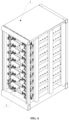
FIG. 1 is a schematic view showing the structure of a battery energy storage system according to an embodiment of the present application; -
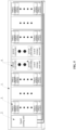
FIG. 2 is a schematic view showing the structure of a support frame inFIG. 1 ; -
FIG. 3 is a schematic view of a battery cluster inFIG. 1 ; -
FIG. 4 is a schematic view showing the structure of the battery cluster; -
FIG. 5 is a schematic view showing the structure of a battery energy storage system according to another embodiment; -
FIG. 6 is a schematic view showing the structure of the battery energy storage system inFIG. 5 ; -
FIG. 7 is a schematic view of a battery energy storage system according to yet another embodiment; -
FIG. 8 is a schematic view of a battery energy storage system according to still another embodiment; -
FIG. 9 is a schematic view of a battery energy storage system according to still yet another embodiment; -
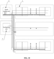
FIG. 10 is a schematic view of a battery energy storage system according to still yet another embodiment; and -
FIG. 11 is a sectional view of a housing of a battery module according to the present application. -
1 support frame, 11 first coolant channel, 12 second coolant channel, 2 liquid cooling unit, 3 battery module, 4 power conversion unit, 5 battery management module, 6 ground platform, 7 firefighting unit, 8 housing of battery module, 81 vacuum chamber. - The object of the present application is to provide a battery energy storage system, the number and position of battery modules of which can be changed flexibly, and therefore is adaptive for flexible deployment on a project site.
- Technical solutions according to the embodiments of the present application will be described clearly and completely as follows in conjunction with the accompany drawings in the embodiments of the present application. It is obvious that the described embodiments are only a part of the embodiments according to the present application, rather than all of the embodiments. All the other embodiments obtained by those skilled in the art based on the embodiments in the present application without any creative work belong to the scope of protection of the present application.
- In the description of the present application, it should be understood that the orientation or positional relationship indicated by the terms "upper", "lower", "front", "back", "left", "right", etc. are based on those shown in the accompanying drawings, and are merely for the convenience of describing the present application and the simplification of the description, and do not indicate or imply that the device or element referred to must have a particular orientation, or be configured and operated in a particular orientation, which therefore should not be construed as a limitation to the scope of the present application. In addition, terms such as "first", "second" and the like are merely for description, and should not be construed as indicating or implying relative importance.
- With reference to
FIG. 1 to FIG. 10 , a battery energy storage system according to the present application includes aliquid cooling unit 2, a support structure andmultiple battery modules 3. - The
liquid cooling unit 2 includes a coolant outlet and a coolant inlet, where a coolant flows into theliquid cooling unit 2 through the coolant inlet. Theliquid cooling unit 2 performs refrigeration to the coolant, to reduce the temperature of the coolant entered into theliquid cooling unit 2, and the coolant after refrigeration is discharged through the coolant outlet of theliquid cooling unit 2. - The support structure is at least partially open, i.e. the support structure is provided with a fitting hole, through which the battery module can get in and out of the support structure. A
first coolant channel 11 and asecond coolant channel 12 are provided inside the support structure, i.e. thefirst coolant channel 11 and thesecond coolant channel 12 are pre-manufactured inside the support structure, with only an inlet of thefirst coolant channel 11 and an outlet of thesecond coolant channel 12 being exposed on the surface of the support structure. The inlet of thefirst coolant channel 11 is in communication with the coolant outlet of theliquid cooling unit 2, and the outlet of thesecond coolant channel 12 is in communication with the coolant inlet of theliquid cooling unit 2. - The
multiple battery modules 3 are mounted on the support structure. Specifically, themultiple battery modules 3 are fixed on the support structure. The support structure may include a support beam, and thebattery modules 3 are fixedly connected to the support beam. - Each of the
battery modules 3 is provided with a heat exchanger thereinside, where a coolant inlet of the heat exchanger is in communication with the outlet of thefirst coolant channel 11, and a coolant outlet of the heat exchanger is in communication with the inlet of thesecond coolant channel 12. The coolant from theliquid cooling unit 2 flows through thefirst coolant channel 11, the heat exchangers of thebattery modules 3, and thesecond coolant channel 12 in sequence, then flows back to theliquid cooling unit 2. The coolant carries the heat inside thebattery modules 3 away when flowing through the heat exchangers of thebattery modules 3, to cool the batteries. The heat exchangers of themultiple battery modules 3 may be in parallel or in series, or, the heat exchangers of a part of thebattery modules 3 may be in series, and then be arranged in parallel with the heat exchangers of the other part of thebattery modules 3. - A
housing 8 of thebattery module 3 is waterproof and dustproof, specifically with an ingress protection rating of at least IP54. - According to the battery energy storage system in the present application, the support structure is provided with the
first coolant channel 11 and thesecond coolant channel 12 thereinside, through which theliquid cooling unit 2 is in communication with the heat exchangers of thebattery modules 3, so that the coolant from theliquid cooling unit 2 flows through thefirst coolant channel 11, the heat exchangers of thebattery modules 3, and thesecond coolant channel 12 in sequence, then flows back to theliquid cooling unit 2, to dissipate the heat in the batteries. - It is known from above that, since the
first coolant channel 11 and thesecond coolant channel 12 are both pre-manufactured inside the support structure, and the support structure is at least partially open, i.e. the support structure is provided with the fitting hole, through which the battery module can get in and out of the support structure, the number and the positions of the battery modules may be adjusted through the fitting hole in the support structure, to be adapted to the on-site projects, which is beneficial to flexible deployment on the project site. - In a specific embodiment, the support structure may include a
support frame 1. Thesupport frame 1 includes multiple support beams, where thefirst coolant channel 11 and thesecond coolant channel 12 may be located inside the support beams, and thefirst coolant channel 11 and thesecond coolant channel 12 may extend along the support beams. Specifically, the support beams may include multiple transverse beams and multiple longitudinal beams. Of course, the structure of thesupport frame 1 may be designed based on actual conditions, which is not limited herein. - In another embodiment, the support structure includes a support platform, where the
multiple battery modules 3 may be fixed on the support platform. - Further, the support platform may be a
ground platform 6 or a metal platform. Of course, the support platform may also be made of other materials. The support platform may be provided with thesupport frame 1 thereon, to fix themultiple battery modules 3. Of course, thesupport frame 1 may include a baseplate, which is not limited herein. - The support structure may also be a warehouse, which is not limited herein.
- To facilitate connection, the outlet of the
first coolant channel 11 may be in communication with the coolant inlet of the heat exchanger through a detachable adapter; and the coolant outlet of the heat exchanger may be in communication with the inlet of thesecond coolant channel 12 through a detachable adapter, which facilitates the disassembly and assembly of thebattery modules 3. Specifically, multiple adapters are reserved on the surface of the support structure. When mounting thebattery modules 3, the heat exchangers of thebattery modules 3 may be connected to the adapters nearby. The adapters may be sealed when not required. - In a specific embodiment, the battery energy storage system further includes any one or more of a
battery management module 5 and apower conversion unit 4 fixed on the support structure. In this way, thebattery management module 5, thepower conversion unit 4 and thebattery modules 3, which are independent to each other, may be integrated on one or more support structures, making the management and the transportation more convenient. Thebattery management module 5 is mainly for on-off control of the battery clusters, and for monitoring and managing the state of the battery clusters. - A
housing 8 of a temperature control unit, ahousing 8 of thebattery management module 5 and ahousing 8 of thepower conversion unit 4 are waterproof and dustproof, with an ingress protection rating of at least IP54. - As shown in
FIG.1 andFIG.5 , theliquid cooling unit 2 may be fixed on the support structure. Of course, theliquid cooling unit 2 may not be fixed on the support structure, and the position of theliquid cooling unit 2 may be determined according to actual conditions. - As shown in
FIG.2 andFIG.3 , the battery energy storage system may include at least one battery cluster, which includesmultiple battery modules 3 arranged in a stacked manner. Themultiple battery modules 3 arranged in the stacked manner may be in parallel connection. When multiple battery clusters are provided, the multiple battery clusters may be arranged one after another. - As shown in
FIGs. 1 to 4 , according to a first embodiment of the present application, thesupport frame 1 is provided with a placement area for theliquid cooling unit 2, a placement area for thepower conversion unit 4, a placement area for thebattery management module 5 and multiple placement areas for thebattery modules 3. Specifically, theliquid cooling unit 2 is fixed at the placement area for theliquid cooling unit 2; the multiple battery clusters are fixed at the multiple placement areas for the battery modules, respectively; thepower conversion unit 4 is fixed at the placement area for thepower conversion unit 4; and thebattery management module 5 is fixed at the placement area for thebattery management module 5. The multiple battery clusters are arranged one after another, and thepower conversion unit 4 is above thebattery management module 5. - In the first embodiment, the battery management module may be arranged below the multiple stacked
battery modules 3 in the battery cluster. - As shown in
FIGs.5 and6 , according to a second embodiment of the present application, thesupport frame 1 is provided with a placement area for theliquid cooling unit 2, a placement area for thepower conversion unit 4, a placement area for thebattery management module 5 and multiple placement areas for thebattery modules 3. Specifically, theliquid cooling unit 2 is fixed at the placement area for theliquid cooling unit 2; the multiple battery clusters are fixed at the multiple placement areas for thebattery modules 3, respectively; thepower conversion unit 4 is fixed at the placement area for thepower conversion unit 4; and thebattery management module 5 is fixed at the placement area for thebattery management module 5. Thepower conversion unit 4 is above thebattery management module 5, and the multiple battery clusters are arranged on both sides of thepower conversion unit 4 and thebattery management module 5. - As shown in
FIG. 7 , according to a third embodiment of the present application, thepower conversion unit 4 is above thebattery management module 5, theliquid cooling unit 2 is located at one side of the support structure in a longitudinal direction thereof, thepower conversion unit 4 and thebattery management module 5 are located at the other side of the support structure in the longitudinal direction thereof, and the multiple battery clusters are arranged one after another between theliquid cooling unit 2 and thepower conversion unit 4. - As shown in
FIG. 8 , in the third embodiment, thebattery management module 5 may be arranged below the multiple stackedbattery modules 3 in the battery cluster. - As shown in
FIG. 9 , according to a forth embodiment of the present application, the number of the support structure is plural, and the multiple support structures may be fixed on theground platform 6 one after another, which makes it easy to assemble and more stable, where theliquid cooling unit 2 is fixed in at least one of the support structures; the battery cluster and thebattery management module 5 on a top of or at a bottom of the battery cluster are fixed in at least another one of the support structures; and thepower conversion unit 4 is fixed in at least yet another one of the support structures. By such arrangement, theliquid cooling unit 2 and the battery cluster which are independent from each other can be integrated. - As shown in
FIG. 10 , the number of the support structure is plural, where theliquid cooling unit 2 is in communication with thefirst coolant channels 11 and thesecond coolant channels 12 of the multiple support structures. In this way, theliquid cooling unit 2 can supply coolant to the battery clusters fixed on the multiple support structures, so that the multiple battery clusters may share theliquid cooling unit 2, which reduces the cost and simplifies the structure. - The number of the support structure is plural. The battery energy storage system further includes a
firefighting unit 7, which includes multiple fire extinguishing pipelines arranged in parallel and multiple detection and alarm modules arranged in parallel, where the multiple fire extinguishing pipelines are configured to provide extinguishing media to the battery clusters in the multiple support structures respectively. Specifically, when the battery cluster is on fire, the extinguishing media is supplied into the battery cluster to put out the fire. The multiple detection and alarm modules are configured to detect whether the battery clusters in the multiple support structures are on fire and raise an alarm once the fire starts, respectively. Specifically, the detection and alarm modules alert the workers upon detecting the fire in the battery cluster. By such arrangement, the multiple battery clusters share thefirefighting unit 7, which reduces the cost and simplifies the structure. - The extinguishing media may be water, water mist, perfluoro, heptafluoropropane or aerosol, which is not limited herein.
- To keep the internal temperature of the
battery module 3, avacuum chamber 81 or a thermal insulation layer may be provided inside thehousing 8 of thebattery module 3. - Additionally, to enhance the explosion-proof performance, a pressure relief port is provided in the
housing 8 of thebattery module 3, where a pressure limiting valve is arranged at the pressure relief port. When the pressure in thehousing 8 of thebattery module 3 reaches a preset value, the pressure may be relieved through the pressure limiting valve. - The above embodiments in this specification are described in a progressive manner. Each of the embodiments is mainly focused on describing its differences from other embodiments, and references may be made among these embodiments with respect to the same or similar portions among these embodiments.
- Based on the above description of the disclosed embodiments, those skilled in the art are capable of carrying out or using the present application. It is obvious for those skilled in the art to make many modifications to these embodiments. The general principle defined herein may be applied to other embodiments without departing from the spirit or scope of the present application. Therefore, the present application is not limited to the embodiments illustrated herein, but should be defined by the broadest scope consistent with the principle and novel features disclosed herein.
- In the description of this specification, descriptions referring to the terms "one embodiment", "example", "specific example", etc., mean that specific features, structures, materials or characteristics described in connection with the embodiment or example are included in at least one embodiment of the present application. In this specification, schematic expressions of the above terms do not necessarily refer to the same embodiment or example. Furthermore, the specific features, structures, materials or characteristics described may be combined in any suitable manner in any one or more embodiments or examples.
Claims (12)
- A battery energy storage system, comprising:a liquid cooling unit (2) having a coolant outlet and a coolant inlet;a support structure, wherein the support structure is at least partially open, a first coolant channel (11) and a second coolant channel (12) are provided inside the support structure, an inlet of the first coolant channel (11) is in communication with the coolant outlet of the liquid cooling unit (2), and an outlet of the second coolant channel (12) is in communication with the coolant inlet of the liquid cooling unit (2); anda plurality of battery modules (3) mounted on the support structure, wherein a heat exchanger is provided inside each of the plurality of battery modules (3), a coolant inlet of the heat exchanger is in communication with an outlet of the first coolant channel (11), and a coolant outlet of the heat exchanger is in communication with an inlet of the second coolant channel (12); and wherein a coolant from the liquid cooling unit (2) is configured to flow through the first coolant channel (11), the heat exchangers of the plurality of battery modules, and the second coolant channel (12) in sequence, and flow back to the liquid cooling unit (2).
- The battery energy storage system according to claim 1, wherein the support structure comprises a support frame (1), and the support frame (1) comprises a plurality of support beams.
- The battery energy storage system according to claim 1, wherein the support structure comprises a support platform, and the support platform is a ground platform (6) or a metal platform.
- The battery energy storage system according to claim 1, wherein the outlet of the first coolant channel (11) is in communication with the coolant inlet of the heat exchanger through a detachable adapter, and the coolant outlet of the heat exchanger is in communication with the inlet of the second coolant channel (12) through another detachable adapter.
- The battery energy storage system according to claim 1, further comprising any one or more of a battery management module (5) and a power conversion unit (4) fixed on the support structure, wherein a housing of the battery management module (5) and a housing of the power conversion unit (4) are dustproof and waterproof.
- The battery energy storage system according to claim 1, wherein the liquid cooling unit (2) is fixed on the support structure.
- The battery energy storage system according to claim 3, comprising at least one battery cluster, wherein the battery cluster includes a plurality of battery modules (3) arranged in a stacked manner.
- The battery energy storage system according to claim 7, wherein the number of the support structure is plural, and the plurality of support structures are fixed on the ground platform one after another, wherein
the liquid cooling unit (2) is fixed in at least one of the plurality of support structures; the battery cluster and the battery management module located at a bottom or a top of the battery cluster are fixed in at least another one of the plurality of support structures; and the power conversion unit (4) is fixed in at least yet another one of the plurality of support structures. - The battery energy storage system according to claim 1, wherein the number of the support structure is plural, wherein the liquid cooling unit (2) is in communication with the first coolant channels (11) and the second coolant channels (12) of the plurality of the support structures.
- The battery energy storage system according to claim 1, wherein the number of the support structure is plural, the battery energy storage system further comprises a firefighting unit (7), the firefighting unit (7) comprises a plurality of fire extinguishing pipelines provided in parallel and a plurality of detection and alarm modules provided in parallel; and wherein
the plurality of fire extinguishing pipelines are configured to provide extinguishing media to battery clusters in the plurality of the support structures, respectively; and the plurality of detection and alarm modules are configured to detect whether the battery clusters in the plurality of support structures are on fire and raise an alarm once the fire starts, respectively. - The battery energy storage system according to claim 1, wherein a vacuum chamber (81) or a thermal insulation layer is provided inside a housing (8) of the battery module (3).
- The battery energy storage system according to claim 1, wherein a pressure relief port is provided in a housing (8) of the battery module (3), and a pressure limiting valve is arranged at the pressure relief port.
Applications Claiming Priority (2)
| Application Number | Priority Date | Filing Date | Title |
|---|---|---|---|
| CN202123136324.2U CN217426867U (en) | 2021-12-13 | 2021-12-13 | Energy storage battery system |
| PCT/CN2022/094452 WO2023109010A1 (en) | 2021-12-13 | 2022-05-23 | Energy storage battery system |
Publications (2)
| Publication Number | Publication Date |
|---|---|
| EP4379906A1 true EP4379906A1 (en) | 2024-06-05 |
| EP4379906A4 EP4379906A4 (en) | 2025-08-27 |
Family
ID=83169029
Family Applications (1)
| Application Number | Title | Priority Date | Filing Date |
|---|---|---|---|
| EP22905778.1A Pending EP4379906A4 (en) | 2021-12-13 | 2022-05-23 | ENERGY STORAGE BATTERY SYSTEM |
Country Status (5)
| Country | Link |
|---|---|
| US (1) | US20240387941A1 (en) |
| EP (1) | EP4379906A4 (en) |
| CN (1) | CN217426867U (en) |
| AU (1) | AU2022408296B2 (en) |
| WO (1) | WO2023109010A1 (en) |
Cited By (1)
| Publication number | Priority date | Publication date | Assignee | Title |
|---|---|---|---|---|
| EP4614693A1 (en) * | 2024-03-05 | 2025-09-10 | Eve Energy Storage Co., Ltd | Energy storage system |
Families Citing this family (4)
| Publication number | Priority date | Publication date | Assignee | Title |
|---|---|---|---|---|
| MX2023003107A (en) * | 2022-03-16 | 2023-09-18 | Stewart & Stevenson Llc | Mobile energy storage system and integrated skid base. |
| CN118120100A (en) * | 2022-09-30 | 2024-05-31 | 宁德时代新能源科技股份有限公司 | Energy storage device |
| CN221102281U (en) * | 2023-09-28 | 2024-06-07 | 宁德时代新能源科技股份有限公司 | Energy storage system and micro-grid system |
| CN117792122A (en) * | 2024-02-23 | 2024-03-29 | 中宏科创新能源科技(浙江)有限公司 | Current conversion assembly, energy storage current transformer and energy storage system |
Family Cites Families (7)
| Publication number | Priority date | Publication date | Assignee | Title |
|---|---|---|---|---|
| CN208753472U (en) * | 2018-05-18 | 2019-04-16 | 力神动力电池系统有限公司 | Liquid cooling battery pack |
| DE102018114462A1 (en) * | 2018-06-15 | 2019-12-19 | Liebherr-Components Biberach Gmbh | Energy storage device |
| CN109638189A (en) * | 2018-12-11 | 2019-04-16 | 威马汽车科技集团有限公司 | A kind of included water route Battery case structure |
| CN213212309U (en) * | 2020-10-30 | 2021-05-14 | 比亚迪股份有限公司 | energy storage system |
| CN112968239A (en) * | 2021-03-25 | 2021-06-15 | 北京海博思创科技股份有限公司 | Energy storage battery cabinet |
| CN215070123U (en) * | 2021-04-23 | 2021-12-07 | 阳光储能技术有限公司 | A liquid cooling pipeline structure, liquid cooling system and energy storage device |
| CN114284628B (en) * | 2021-12-17 | 2023-12-05 | 上海瑞浦青创新能源有限公司 | Box-type energy storage battery system |
-
2021
- 2021-12-13 CN CN202123136324.2U patent/CN217426867U/en active Active
-
2022
- 2022-05-23 AU AU2022408296A patent/AU2022408296B2/en active Active
- 2022-05-23 US US18/692,466 patent/US20240387941A1/en active Pending
- 2022-05-23 WO PCT/CN2022/094452 patent/WO2023109010A1/en not_active Ceased
- 2022-05-23 EP EP22905778.1A patent/EP4379906A4/en active Pending
Cited By (1)
| Publication number | Priority date | Publication date | Assignee | Title |
|---|---|---|---|---|
| EP4614693A1 (en) * | 2024-03-05 | 2025-09-10 | Eve Energy Storage Co., Ltd | Energy storage system |
Also Published As
| Publication number | Publication date |
|---|---|
| WO2023109010A1 (en) | 2023-06-22 |
| AU2022408296B2 (en) | 2026-01-22 |
| CN217426867U (en) | 2022-09-13 |
| EP4379906A4 (en) | 2025-08-27 |
| US20240387941A1 (en) | 2024-11-21 |
| AU2022408296A1 (en) | 2024-03-28 |
Similar Documents
| Publication | Publication Date | Title |
|---|---|---|
| EP4379906A1 (en) | Energy storage battery system | |
| EP1308073B1 (en) | Electronic enclosure cooling system | |
| US20210092866A1 (en) | Fluid-cooled data centres without air coinditioning, and methods for operating same | |
| US11184996B1 (en) | Double sided heat exchanger cooling unit | |
| US12178019B2 (en) | Coolant system for a busbar assembly | |
| US20260051569A1 (en) | Energy storage system | |
| EP4514080A1 (en) | Flexible fluid-cooling heat dissipation unit | |
| US20250380381A1 (en) | Energy storage system | |
| AU2023369243A1 (en) | Supplementary electrical cabinet and energy storage power station | |
| CN219106299U (en) | Battery pack and power utilization device | |
| EP4622028A1 (en) | Container and photovoltaic power station | |
| WO2025044686A1 (en) | Thermal management device and energy storage system | |
| CN219124510U (en) | Device for placing information management equipment | |
| CN215266443U (en) | Energy storage cabinet | |
| CN220401248U (en) | UPS power supply cabinet body structure | |
| CN212746728U (en) | Wall-mounted explosion-proof air conditioner | |
| CN221202935U (en) | Containers and container data centers | |
| CN213586814U (en) | High-power heat radiation structure of protectiveness closed-loop control | |
| CN220582802U (en) | Secondary heat abstractor of high temperature environment air conditioner | |
| CN217768538U (en) | Air-cooling heat dissipation mechanism of air conditioner for energy storage cabinet | |
| CN217788538U (en) | Air-cooled battery box and battery pack | |
| CN220830019U (en) | Battery box and battery pack | |
| CN222925639U (en) | Air-cooled box type water chiller | |
| CN115776780A (en) | Edge calculation micromodule | |
| CN222914891U (en) | Battery module and vehicle |
Legal Events
| Date | Code | Title | Description |
|---|---|---|---|
| STAA | Information on the status of an ep patent application or granted ep patent |
Free format text: STATUS: THE INTERNATIONAL PUBLICATION HAS BEEN MADE |
|
| PUAI | Public reference made under article 153(3) epc to a published international application that has entered the european phase |
Free format text: ORIGINAL CODE: 0009012 |
|
| STAA | Information on the status of an ep patent application or granted ep patent |
Free format text: STATUS: REQUEST FOR EXAMINATION WAS MADE |
|
| 17P | Request for examination filed |
Effective date: 20240229 |
|
| AK | Designated contracting states |
Kind code of ref document: A1 Designated state(s): AL AT BE BG CH CY CZ DE DK EE ES FI FR GB GR HR HU IE IS IT LI LT LU LV MC MK MT NL NO PL PT RO RS SE SI SK SM TR |
|
| DAV | Request for validation of the european patent (deleted) | ||
| DAX | Request for extension of the european patent (deleted) | ||
| A4 | Supplementary search report drawn up and despatched |
Effective date: 20250725 |
|
| RIC1 | Information provided on ipc code assigned before grant |
Ipc: H01M 10/613 20140101AFI20250721BHEP Ipc: H01M 10/627 20140101ALI20250721BHEP Ipc: H01M 10/6568 20140101ALI20250721BHEP Ipc: H01M 50/251 20210101ALI20250721BHEP Ipc: H01M 50/317 20210101ALI20250721BHEP Ipc: H01M 10/48 20060101ALI20250721BHEP Ipc: H01M 10/6556 20140101ALI20250721BHEP Ipc: H01M 10/6567 20140101ALI20250721BHEP Ipc: H01M 50/204 20210101ALI20250721BHEP |