EP4379491A1 - Ship control system, control method, and control program for ship control system - Google Patents
Ship control system, control method, and control program for ship control system Download PDFInfo
- Publication number
- EP4379491A1 EP4379491A1 EP23205822.2A EP23205822A EP4379491A1 EP 4379491 A1 EP4379491 A1 EP 4379491A1 EP 23205822 A EP23205822 A EP 23205822A EP 4379491 A1 EP4379491 A1 EP 4379491A1
- Authority
- EP
- European Patent Office
- Prior art keywords
- ship
- control
- speed
- actual
- turning
- Prior art date
- Legal status (The legal status is an assumption and is not a legal conclusion. Google has not performed a legal analysis and makes no representation as to the accuracy of the status listed.)
- Pending
Links
Images



Classifications
-
- G—PHYSICS
- G05—CONTROLLING; REGULATING
- G05D—SYSTEMS FOR CONTROLLING OR REGULATING NON-ELECTRIC VARIABLES
- G05D1/00—Control of position, course, altitude or attitude of land, water, air or space vehicles, e.g. using automatic pilots
- G05D1/40—Control within particular dimensions
- G05D1/43—Control of position or course in two dimensions [2D]
-
- B—PERFORMING OPERATIONS; TRANSPORTING
- B63—SHIPS OR OTHER WATERBORNE VESSELS; RELATED EQUIPMENT
- B63B—SHIPS OR OTHER WATERBORNE VESSELS; EQUIPMENT FOR SHIPPING
- B63B79/00—Monitoring properties or operating parameters of vessels in operation
- B63B79/40—Monitoring properties or operating parameters of vessels in operation for controlling the operation of vessels, e.g. monitoring their speed, routing or maintenance schedules
-
- B—PERFORMING OPERATIONS; TRANSPORTING
- B63—SHIPS OR OTHER WATERBORNE VESSELS; RELATED EQUIPMENT
- B63B—SHIPS OR OTHER WATERBORNE VESSELS; EQUIPMENT FOR SHIPPING
- B63B49/00—Arrangements of nautical instruments or navigational aids
-
- B—PERFORMING OPERATIONS; TRANSPORTING
- B63—SHIPS OR OTHER WATERBORNE VESSELS; RELATED EQUIPMENT
- B63B—SHIPS OR OTHER WATERBORNE VESSELS; EQUIPMENT FOR SHIPPING
- B63B79/00—Monitoring properties or operating parameters of vessels in operation
- B63B79/10—Monitoring properties or operating parameters of vessels in operation using sensors, e.g. pressure sensors, strain gauges or accelerometers
-
- B—PERFORMING OPERATIONS; TRANSPORTING
- B63—SHIPS OR OTHER WATERBORNE VESSELS; RELATED EQUIPMENT
- B63H—MARINE PROPULSION OR STEERING
- B63H21/00—Use of propulsion power plant or units on vessels
- B63H21/21—Control means for engine or transmission, specially adapted for use on marine vessels
-
- B—PERFORMING OPERATIONS; TRANSPORTING
- B63—SHIPS OR OTHER WATERBORNE VESSELS; RELATED EQUIPMENT
- B63H—MARINE PROPULSION OR STEERING
- B63H25/00—Steering; Slowing-down otherwise than by use of propulsive elements; Dynamic anchoring, i.e. positioning vessels by means of main or auxiliary propulsive elements
- B63H25/06—Steering by rudders
- B63H25/36—Rudder-position indicators
-
- G—PHYSICS
- G05—CONTROLLING; REGULATING
- G05D—SYSTEMS FOR CONTROLLING OR REGULATING NON-ELECTRIC VARIABLES
- G05D1/00—Control of position, course, altitude or attitude of land, water, air or space vehicles, e.g. using automatic pilots
- G05D1/60—Intended control result
- G05D1/65—Following a desired speed profile
-
- B—PERFORMING OPERATIONS; TRANSPORTING
- B63—SHIPS OR OTHER WATERBORNE VESSELS; RELATED EQUIPMENT
- B63B—SHIPS OR OTHER WATERBORNE VESSELS; EQUIPMENT FOR SHIPPING
- B63B79/00—Monitoring properties or operating parameters of vessels in operation
- B63B79/20—Monitoring properties or operating parameters of vessels in operation using models or simulation, e.g. statistical models or stochastic models
-
- B—PERFORMING OPERATIONS; TRANSPORTING
- B63—SHIPS OR OTHER WATERBORNE VESSELS; RELATED EQUIPMENT
- B63H—MARINE PROPULSION OR STEERING
- B63H21/00—Use of propulsion power plant or units on vessels
- B63H21/21—Control means for engine or transmission, specially adapted for use on marine vessels
- B63H2021/216—Control means for engine or transmission, specially adapted for use on marine vessels using electric control means
-
- B—PERFORMING OPERATIONS; TRANSPORTING
- B63—SHIPS OR OTHER WATERBORNE VESSELS; RELATED EQUIPMENT
- B63H—MARINE PROPULSION OR STEERING
- B63H25/00—Steering; Slowing-down otherwise than by use of propulsive elements; Dynamic anchoring, i.e. positioning vessels by means of main or auxiliary propulsive elements
-
- G—PHYSICS
- G05—CONTROLLING; REGULATING
- G05D—SYSTEMS FOR CONTROLLING OR REGULATING NON-ELECTRIC VARIABLES
- G05D2107/00—Specific environments of the controlled vehicles
- G05D2107/25—Aquatic environments
- G05D2107/27—Oceans
-
- G—PHYSICS
- G05—CONTROLLING; REGULATING
- G05D—SYSTEMS FOR CONTROLLING OR REGULATING NON-ELECTRIC VARIABLES
- G05D2109/00—Types of controlled vehicles
- G05D2109/30—Water vehicles
- G05D2109/34—Water vehicles operating on the water surface
Definitions
- the present invention relates to a ship control system, a control method for a ship control system, and a control program for a ship control system.
- Patent Literature 1 describes a ship control system that includes a propelling device mounted on a ship, and a controller for controlling the propulsion of the propelling device.
- This system includes an auto-cruise command device, a device for setting a target ship speed, and a device for detecting the actual ship speed of the ship.
- the controller controls the propulsion of the propelling device so that the difference between the target ship speed and the actual ship speed falls within a predetermined speed range.
- the controller performs control with propulsion different from that in normal times when an interrupt condition is satisfied.
- Patent Literature 1 Japanese Unexamined Patent Application Publication No. 2017-094945
- Patent Literature 1 a proposal is made to increase the main engine torque during ship speed control, upon detection of the rudder being operated or detection of the yaw rate of the ship. Since a fluctuation of the main engine load affects the turning speed, unnecessary rudder operation is required when an autopilot is used. Also, the ship speed control and the rudder angle control may interfere with each other during turning, which may cause unnecessary load fluctuations on the main engine. Such load fluctuations on the main engine may lead to increased fuel consumption of the main engine.
- the present invention has been made in view of such an issue, and a purpose thereof is to provide a technology for a ship control system capable of reducing unnecessary load fluctuations on the main engine during turning.
- a ship control system includes: a main engine controller that performs, when controlling the rotational frequency of a main engine based on a target ship speed of a ship, feedback control of an actual ship speed of the ship to perform ship speed control for bringing the actual ship speed closer to the target ship speed; a turning judgment unit that judges whether or not the ship will turn; and a control change unit that performs, when the turning judgment unit has judged that the ship will turn, lowering processing for lowering the responsiveness of the ship speed control.
- an object when an object is constituted by multiple objects, the multiple objects may be integrated together, and, conversely, an object constituted by a single object may be divided into multiple objects. Regardless of whether the objects are integrated or not, configurations have only to be made such that a purpose of the invention can be achieved.
- a ship control system includes: a main engine controller that performs, when controlling the rotational frequency of a main engine based on a target ship speed of a ship, feedback control of an actual ship speed of the ship to perform ship speed control for bringing the actual ship speed closer to the target ship speed; a turning judgment unit that judges whether or not the ship will turn; and a control change unit that performs, when the turning judgment unit has judged that the ship will turn, lowering processing for lowering the responsiveness of the ship speed control.
- the lowering processing can be performed when a ship turns.
- unnecessary load fluctuations of the main engine during turning can be reduced, and an increase in fuel consumption can be suppressed.
- the ship speed control when it is judged that the ship will turn, the ship speed control is stopped, and control is performed such as to maintain the rotational frequency of the main engine at the time of the judgment.
- the lowering processing can be performed by stopping the ship speed control.
- loop gain of the feedback control is made smaller than that before it is judged that the ship will turn.
- the lowering processing can be performed by reducing the loop gain.
- the turning judgment unit judges whether or not the ship will turn using an actual rudder angle of the ship. In this case, whether or not the ship will turn can be easily judged using the actual rudder angle.
- the turning judgment unit judges that the turning of the ship has been finished. In this case, the finish of turning can be easily judged using the actual rudder angle.
- the turning judgment unit judges whether or not the ship will turn using a result of comparison between a target rudder angle and the actual rudder angle of the ship. In this case, since the judgment can be made in advance using the comparison result regarding the rudder angle, the lowering processing can be started earlier. Therefore, load fluctuations of the main engine during turning can be suppressed.
- the turning judgment unit judges turning of the ship further using disturbance information including at least one of the speed of a tidal current near the ship, the direction of a tidal current near the ship, the wind speed near the ship, or the wind direction near the ship.
- disturbance information including at least one of the speed of a tidal current near the ship, the direction of a tidal current near the ship, the wind speed near the ship, or the wind direction near the ship.
- the control change unit disables the lowering processing.
- the ship speed control can be returned from the lowering processing mode to the normal mode.
- the turning judgment unit judges whether or not the ship will turn using an actual ship position of the ship and a way point on a navigation plan of the ship. In this case, even if there is a delay from when the rudder is operated until when the influence on the actual ship speed appears in the ship, the lowering processing can be started earlier, so that load fluctuations of the main engine during turning can be suppressed.
- the turning judgment unit estimates a scheduled time at which the ship reaches the way point and judges that the ship will turn a predetermined period of time before the scheduled time. In this case, since the turning judgment can be made when the ship approaches a way point, the lowering processing can be started earlier.
- FIG. 1 schematically illustrates the ship control system 10 according to the first embodiment of the present invention.
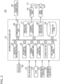
- FIG. 2 is a schematic block diagram of the ship control system 10.
- FIG. 2 illustrates functional blocks implemented by coordination of those components. Therefore, it will be understood by those skilled in the art that these functional blocks may be implemented in a variety of forms by combinations of hardware and software.
- a ship 1 includes a hull 90, an information processing unit 12, a main engine 74, a steering gear 76, a GPS receiver 14, and a gyro 15.
- the ship control system 10 is provided in the ship 1.
- the main engine 74 is an engine that propels the ship 1 and is a propulsion mechanism that rotates a propeller 75 to generate propulsion for propelling the hull 90.
- the main engine 74 has only to be capable of propelling the hull 90 and is a diesel engine in this example.
- the main engine 74 consumes an amount of fuel corresponding to the rotational frequency and torque of the main engine 74 in order to operate the main engine 74.
- the main engine 74 may be provided with a governor, not illustrated, that fine-tunes the fuel input in order to suppress fluctuations in rotational speed in response to load changes in the main engine 74.
- the steering gear 76 is a power steering mechanism that rotates a rudder 77 provided on the hull to turn the ship 1.
- the steering gear 76 changes the rudder angle using power from a power source, such as a hydraulic actuator or an electric motor.
- the steering gear 76 includes a rudder angle detector 31 that detects the actual rudder angle.
- the rudder angle detector 31 provides the actual rudder angle thus detected to the information processing unit 12.
- the GPS receiver 14 calculates the current position of the receiver using satellite radio waves and provides the calculated current position as the actual ship position to the information processing unit 12.
- the GPS receiver 14 has only to be capable of calculating the current position of the receiver using satellite radio waves and is not limited to any particular system.
- the GPS receiver 14 of the embodiment is a global positioning system that receives positioning signals from several satellites in the sky among multiple satellites and calculates the current position of the receiver.
- the gyro 15 acquires the attitude of the ship 1, identifies the actual bow direction of the ship 1 from the acquired attitude, and provides the actual bow direction to the information processing unit 12.
- the information processing unit 12 mainly includes a navigation information device 16, an automatic steering unit 25, a turning judgment unit 21, a control change unit 22, a correction unit 26, a communication unit 28, a propulsion controller 17, and a storage unit 29.
- the communication unit 28 transmits and receives information to and from outside the ship 1.
- the storage unit 29 stores the target ship speed, actual ship speed, target rudder angle, actual rudder angle, and the like in chronological order.
- the storage unit 29 also stores a control program P100 for the ship control system 10.
- ship speed such as the target ship speed and actual ship speed may be the ship speed over the ground, may be the ship speed through the water, or may be the rotational speed of the main engine 74.
- the turning judgment unit 21 judges whether or not the ship 1 will turn (hereinafter, it may be referred to as "turning judgment”).
- the turning judgment unit 21 also judges whether or not turning of the ship 1 has been finished (hereinafter, it may be referred to as “finish judgment”).
- finish judgment judges whether or not turning of the ship 1 has been finished.
- the control change unit 22 performs lowering processing to lower the responsiveness of the ship speed control. Also, when the turning judgment unit 21 has made the finish judgment, the control change unit 22 disables the lowering processing.
- the correction unit 26 provides, to the main engine controller 18, correction information for correcting the rotational frequency of the main engine 74 using a hull motion model 27.
- the turning judgment unit 21, control change unit 22, and correction unit 26 will be detailed later.
- the navigation information device 16 Based on a navigation plan, the navigation information device 16 acquires the current position of the ship 1 (hereinafter, it may be referred to as the "actual ship position"), the destination position, a way point on the route from the actual ship position to the destination position, the scheduled arrival time, the route, and the target ship speed to generate marine chart information and displays the marine chart information on a display 55.
- the navigation information device 16 can acquire the navigation plan in advance before the start of the navigation of the ship 1. Also, during the navigation of the ship 1, the navigation information device 16 can acquire the navigation plan based on weather routing in which weather and marine information is taken into account, from a navigation planning device 50 provided on land and via the communication unit 28.
- the navigation information device 16 of the embodiment includes the Electronic Chart Display and Information System (ECDIS).
- ECDIS Electronic Chart Display and Information System
- the navigation information device 16 receives the actual ship position and the actual bow direction from the GPS receiver 14 and the gyro 15.
- the display 55 displays information such as a way point and the scheduled passing time thereof, the actual ship position, and the actual bow direction.
- the navigation information device 16 in this example is capable of calculating the current ship speed (hereinafter, referred to as the "actual ship speed") by differentiating a change in the actual ship position with respect to time and also calculating the target ship speed and a target bow direction required to pass the next way point at the scheduled passing time thereof.
- the navigation information device 16 provides, to the propulsion controller 17, the actual ship position, actual bow direction, actual ship speed, target ship speed, target bow direction, and the position of a way point.
- the actual ship speed and the target ship speed are provided to the main engine controller 18.
- the navigation information device 16 also provides the target bow direction to the automatic steering unit 25.
- the automatic steering unit 25 functions as an autopilot.
- the automatic steering unit 25 calculates the target bow direction and target rudder angle using information regarding the next way point provided by the navigation information device 16.
- the automatic steering unit 25 may calculate the target rudder angle by controlling the rudder 77 so that the bow always points to the next way point (Heading Control), or by tracing an assumed route to the next way point (Tracking Control), for example.
- the automatic steering unit 25 provides the target rudder angle thus calculated to the steering controller 19.
- the propulsion controller 17 includes the main engine controller 18 that controls the main engine 74, and the steering controller 19 that controls the steering gear 76.
- the main engine controller 18 controls the rotational frequency of the main engine 74 of the ship 1 and performs ship speed control for bringing the actual ship speed of the ship 1 closer to the target ship speed.
- the ship speed control may include, for example, feedback control of calculating the deviation of the actual ship speed from the target ship speed and controlling the main engine 74 so as to eliminate the deviation.
- the rudder angle detector 31 detects the actual rudder angle of the rudder 77 and provides the actual rudder angle to the information processing unit 12. Using the provided target rudder angle and the actual rudder angle, the steering controller 19 controls the steering gear 76 of the ship 1 and performs rudder angle control for bringing the actual rudder angle of the rudder 77 closer to the target rudder angle.
- the rudder angle control may include, for example, feedback control of calculating the deviation of the actual rudder angle from the target rudder angle and controlling the steering gear 76 so as to eliminate the deviation.
- ship speed fluctuations during turning unnecessary ship speed fluctuations
- FIG. 3 shows an example of the ship speed fluctuations during turning.
- the main engine controller 18 increases the rotational frequency of the main engine 74 so as to correct the decrease in the actual ship speed by ship speed control (Step S112).
- the rotational frequency of the main engine 74 increases, the actual ship speed also increases (Step S113).
- the steerage is improved, so that the turning speed of the ship 1 increases (Step S114) .
- the automatic steering unit 25 decreases the target rudder angle to correct the increase in the turning speed.
- Step S115 the steering controller 19 decreases the actual rudder angle by rudder angle control.
- the propulsion resistance due to the rudder operation also decreases, so that the actual ship speed increases (Step S116) .
- the main engine controller 18 decreases the rotational frequency of the main engine 74 so as to correct the increase in the actual ship speed by ship speed control (Step S117). As a result, the actual ship speed decreases, and the actual speed of the ship 1 during turning decreases (Step S118).
- Step S119 When the actual speed during turning decreases, the steerage is worsened, so that the turning speed of the ship 1 decreases (Step S119).
- the automatic steering unit 25 increases the target rudder angle to correct the decrease in the turning speed.
- the steering controller 19 increases the actual rudder angle by rudder angle control (Step S120).
- the loop returns to Step S111, and Steps S111 to S120 are repeated.
- the ship speed control and the rudder angle control of the ship 1 interfere with each other, so that the ship speed fluctuations during turning occur, in which ship speed fluctuations and rudder angle fluctuations are repeated.
- fuel is unnecessarily consumed for the acceleration and deceleration of the main engine 74.
- the route of the ship 1 during turning is not stable.
- the ship control system 10 includes the turning judgment unit 21 that judges whether or not the ship 1 will turn, and the control change unit 22 that performs lowering processing for lowering the responsiveness of the ship speed control when the turning judgment unit 21 has judged that the ship 1 will turn.
- the responsiveness of the ship speed control is lowered, a fluctuation in the actual ship speed due to the ship speed control becomes smaller, so that the ship speed fluctuations during turning are suppressed.
- the control change unit 22 provides, to the main engine controller 18, a command as to whether or not to perform the lowering processing (hereinafter, referred to as a "lowering processing command").
- the lowering processing command is turned on when the lowering processing is performed and is turned off when the lowering processing is not performed.
- the main engine controller 18 changes the control mode.
- the control mode when the lowering processing is not performed is referred to as a normal mode, and the control mode when the lowering processing is performed is referred to as a lowering processing mode.
- the first process is a process in which, when it is judged that the ship 1 will turn, the ship speed control is stopped, and control is performed such as to maintain the rotational frequency of the main engine 74 at the time of the judgment.
- the main engine controller 18 stops the response of the ship speed control.
- the first process is a process that does not change the rotational frequency of the main engine 74 even when the actual ship speed changes and the ship speed deviation from the target ship speed becomes large and that maintains the rotational frequency of the main engine 74 in the state before the actual ship speed changes. Therefore, even if the propulsion resistance changes due to rudder operation and hence the actual ship speed changes, the main engine controller 18 will not change the rotational frequency of the main engine 74, thereby significantly suppressing the ship speed fluctuations during turning.
- the second process is a process of making the loop gain of the feedback control smaller than that before it is judged that the ship 1 will turn.
- a control parameter of the feedback control performed by the main engine controller 18 is changed to reduce the loop gain of the open-loop transfer function in the ship speed control.
- the main engine controller 18 changes a control parameter of the feedback control to reduce the loop gain of the ship speed control.
- the loop gain of the ship speed control is reduced by the second process, the change in the rotational frequency of the main engine 74 in response to a change in the actual ship speed becomes more gradual than in the normal mode.
- the main engine controller 18 can keep the change in the rotational frequency of the main engine 74 small, thereby suppressing the ship speed fluctuations during turning.
- the turning judgment unit 21 can employ a first method of using the actual rudder angle for the judgment or a second method of using the actual ship position and a way point for the judgment.
- the turning judgment unit 21 may perform the turning judgment using a method other than the first and second methods.
- the turning judgment unit 21 judges turning of the ship 1 using the actual rudder angle detected by the rudder angle detector 31. For example, the turning judgment unit 21 may judge that the ship 1 will turn when the actual rudder angle exceeds a threshold R1. Based on the judgment by the turning judgment unit 21, the control change unit 22 performs the lowering processing.
- the control change unit 22 disables the lowering processing and returns the main engine controller 18 to the normal mode.
- the lowering processing can be disabled by turning off the lowering processing command.
- the turning judgment unit 21 can also judge the finish of the turning using the actual rudder angle.
- the turning judgment unit 21 may judge that the turning has been finished when the actual rudder angle becomes equal to or smaller than a predetermined value R2, which is smaller the threshold R1, during the lowering processing. By providing hysteresis between the predetermined value R2 and the threshold R1, hunting of the judgment result of the turning judgment unit 21 due to a fluctuation in the actual rudder angle can be avoided.
- the control change unit 22 turns off the lowering processing command.
- the turning judgment unit 21 can judge whether or not the ship 1 will turn using the actual ship position of the ship 1 and a way point on the navigation plan of the ship 1.
- the actual ship position of the ship 1 can be acquired by the GPS receiver.
- the automatic steering unit 25 changes the target rudder angle based on the next way point and turns the ship 1. Therefore, the turning judgment unit 21 may judge that the ship 1 will turn when the distance between the actual ship position and a way point becomes a predetermined distance or shorter.
- the turning judgment unit 21 can also judge the finish of the turning using the actual ship position and a way point. For example, the turning judgment unit 21 may judge that the turning has been finished when the distance between the actual ship position and a way point becomes a predetermined distance or longer during the lowering processing.
- the turning judgment unit 21 estimates a scheduled time at which the ship 1 reaches the way point and can judge that the ship will turn a predetermined period of time before the scheduled time.
- the scheduled time can be calculated by adding, to the current time, the time obtained by dividing the distance between the actual ship position and the way point by the actual ship speed. In this case, since the lowering processing can be started before the turning operation, the ship speed fluctuations during turning can be avoided mostly.
- the turning judgment unit 21 may judge turning of the ship by further using disturbance information including at least one of the speed of a tidal current near the ship 1, the direction of a tidal current near the ship 1, the wind speed near the ship 1, or the wind direction near the ship 1.
- the disturbance information is detected by a disturbance detector 32 using known techniques. By considering the disturbance information in the turning judgment, the turning can be judged more accurately.
- the main engine controller 18 linearly changes the rotational frequency of the main engine 74 with respect to the ship speed deviation between the target ship speed and the actual ship speed; in the present modification, the main engine controller 18 changes the rotational frequency of the main engine 74 nonlinearly with respect to the ship speed deviation. More specifically, the main engine controller 18 changes the rotational frequency of the main engine 74 based on the result of quantizing the ship speed deviation between the target ship speed and the actual ship speed, from the start to the end of turning of the ship 1. That is, in the modification, the responsiveness of the ship speed control is lowered by performing control such that the rotational frequency of the main engine does not change unless the target ship speed and the actual ship speed fluctuate by a certain amount or more.
- FIG. 4 is a timing chart that shows changes in ship speed in the modification.
- FIG. 4 shows an example of changing the rotational frequency of the main engine 74 based on the result of quantizing the ship speed deviation.
- the horizontal axis represents the elapsed time
- the vertical axis represents a ship speed deviation J, a quantized ship speed deviation R, a main engine control command S, and a steering gear control command D.
- the ship speed deviation J is the ship speed deviation between the target ship speed and the actual ship speed and continuously changes in a curved shape.
- the quantized ship speed deviation R is obtained by quantizing the ship speed deviation J through predetermined steps and changes discontinuously in a staircase-like manner.
- the main engine control command S is a command signal output by the main engine controller 18 to the main engine 74 and changes in a staircase-like manner in the opposite direction to the change in the quantized ship speed deviation R.
- the steering gear control command D is a command signal output by the steering controller 19 to the steering gear 76 and changes in a staircase-like manner in the same direction as the change in the quantized ship speed deviation R.
- the target rudder angle may be used.
- the main engine controller 18 changes the rotational frequency of the main engine 74 nonlinearly with respect to the target rudder angle. More specifically, the main engine controller 18 may change the rotational frequency of the main engine 74 when a quantized target rudder angle, which is the result of quantizing the target rudder angle, exceeds a predetermined rudder angle, from the start to the end of turning of the ship 1.
- the rotational frequency of the main engine 74 can be increased before the start of turning, so that fluctuations in the main engine rotational frequency can be suppressed.
- FIG. 5 is a flowchart that shows an operation S120 of the ship control system 10.
- the ship control system 10 performs ship speed control for bringing the actual ship speed of the ship 1 closer to the target ship speed (Step S121).
- the ship control system 10 judges whether or not the ship 1 will turn (Step S122).
- the turning judgment can be performed using the first method or the second method described above, for example.
- the ship control system 10 When it is judged that the ship 1 will turn (Y at Step S122), the ship control system 10 performs lowering processing (Step S123).
- the lowering processing can be performed using the first process or the second process described above, for example.
- the ship control system 10 judges whether or not the turning of the ship 1 has been finished (Step S124).
- the turning finish judgment can be performed with the method of using the actual rudder angle or the method of using the actual ship position and a way point described above, for example.
- Step S125 the ship control system 10 disables the lowering processing. After the lowering processing is disabled, the process returns to Step S121.
- the operation S120 may be performed repeatedly.
- the operation S120 is merely an example, and various modifications can be made.
- the second embodiment of the present invention relates to a control method for the ship control system 10.
- This method includes: performing, when controlling the rotational frequency of the main engine 74 based on a target ship speed of the ship 1, feedback control of the actual ship speed of the ship 1 to perform ship speed control for bringing the actual ship speed closer to the target ship speed (Step S121); judging whether or not the ship 1 will turn (Step S122); and performing, when it is judged that the ship 1 will turn in the judging, lowering processing for lowering the responsiveness of the ship speed control (Step S123) .
- the second embodiment provides functions and effects similar to those of the first embodiment.
- the third embodiment of the present invention relates to a control program P100 (computer program) for the ship control system 10.
- This program P100 causes a computer to execute: performing, when controlling the rotational frequency of the main engine 74 based on a target ship speed of the ship 1, feedback control of the actual ship speed of the ship 1 to perform ship speed control for bringing the actual ship speed closer to the target ship speed (Step S121); judging whether or not the ship 1 will turn (Step S122); and performing, when it is judged that the ship 1 will turn in the judging, lowering processing for lowering the responsiveness of the ship speed control (Step S123).
- the program P100 may be installed as an application program provided with multiple modules corresponding to functional blocks in the information processing unit 12, on a storage (e.g., the storage unit 29) of the information processing unit 12.
- the program P100 may be read into the main memory of a processor (e.g., CPU) of a computer incorporated in the information processing unit 12 and executed.
- a processor e.g., CPU
- the third embodiment provides functions and effects similar to those of the first embodiment.
- the navigation planning device 50 is provided on land
- the present invention is not limited thereto.
- the navigation planning device may be provided on another ship, a flying object, or the like.
- the present invention is not limited thereto.
- a ship speed sensor for detecting the actual ship speed of a ship may be provided, and the actual ship speed may be acquired using the detection result of the ship speed sensor.
- the mechanism for obtaining propulsion has only to be capable of propelling the ship and may be, for example, a configuration in which gas or the like is discharged based on the rotation of the main engine 74, and propulsion is obtained by means of the reaction force of the gas or the like.
- the main engine 74 is a diesel engine
- the present invention is not limited thereto.
- the main engine may be an internal combustion engine other than a diesel engine, or an external combustion engine.
Landscapes
- Engineering & Computer Science (AREA)
- Chemical & Material Sciences (AREA)
- Ocean & Marine Engineering (AREA)
- Mechanical Engineering (AREA)
- Combustion & Propulsion (AREA)
- Remote Sensing (AREA)
- Radar, Positioning & Navigation (AREA)
- Automation & Control Theory (AREA)
- General Physics & Mathematics (AREA)
- Physics & Mathematics (AREA)
- Aviation & Aerospace Engineering (AREA)
- Control Of Vehicle Engines Or Engines For Specific Uses (AREA)
- Control Of Position, Course, Altitude, Or Attitude Of Moving Bodies (AREA)
- Combined Controls Of Internal Combustion Engines (AREA)
Abstract
A ship control system (10) of one embodiment includes: a main engine controller (18) performs, when controlling the rotational frequency of a main engine (74) based on a target ship speed of a ship (1), feedback control of an actual ship speed of the ship (1) to perform ship speed control for bringing the actual ship speed closer to the target ship speed; a turning judgment unit (21) judges whether or not the ship (1) will turn; and a control change unit (22) performs, when the turning judgment unit (21) has judged that the ship (1) will turn, lowering processing for lowering the responsiveness of the ship speed control.
Description
- The present invention relates to a ship control system, a control method for a ship control system, and a control program for a ship control system.
- For example,
Patent Literature 1 describes a ship control system that includes a propelling device mounted on a ship, and a controller for controlling the propulsion of the propelling device. This system includes an auto-cruise command device, a device for setting a target ship speed, and a device for detecting the actual ship speed of the ship. The controller controls the propulsion of the propelling device so that the difference between the target ship speed and the actual ship speed falls within a predetermined speed range. The controller performs control with propulsion different from that in normal times when an interrupt condition is satisfied. - Patent Literature 1:
Japanese Unexamined Patent Application Publication No. 2017-094945 - In
Patent Literature 1, a proposal is made to increase the main engine torque during ship speed control, upon detection of the rudder being operated or detection of the yaw rate of the ship. Since a fluctuation of the main engine load affects the turning speed, unnecessary rudder operation is required when an autopilot is used. Also, the ship speed control and the rudder angle control may interfere with each other during turning, which may cause unnecessary load fluctuations on the main engine. Such load fluctuations on the main engine may lead to increased fuel consumption of the main engine. - The present invention has been made in view of such an issue, and a purpose thereof is to provide a technology for a ship control system capable of reducing unnecessary load fluctuations on the main engine during turning.
- In response to the above issue, a ship control system according to one embodiment of the present invention includes: a main engine controller that performs, when controlling the rotational frequency of a main engine based on a target ship speed of a ship, feedback control of an actual ship speed of the ship to perform ship speed control for bringing the actual ship speed closer to the target ship speed; a turning judgment unit that judges whether or not the ship will turn; and a control change unit that performs, when the turning judgment unit has judged that the ship will turn, lowering processing for lowering the responsiveness of the ship speed control.
- Optional combinations of the above, and implementation of the present invention, including the constituting elements and expressions, in the form of methods, apparatuses, programs, transitory or non-transitory storage medium storing programs, or systems may also be practiced as additional modes of the present invention.
- Embodiments will now be described, by way of example only, with reference to the accompanying drawings which are meant to be exemplary, not limiting, and wherein like elements are numbered alike in several FIGURES, in which:
-
FIG. 1 schematically illustrates a ship to which a ship control system according to a first embodiment of the present invention is applied; -
FIG. 2 is a schematic block diagram of the ship control system shown inFIG. 1 ; -
FIG. 3 shows transition of ship speed fluctuations due to interference between ship speed control and rudder angle control during turning; -
FIG. 4 is a timing chart that shows changes in ship speed in a modification of the ship speed control; and -
FIG. 5 is a flowchart that shows an example of operation of the ship control system shown inFIG. 1 . - In the embodiments disclosed in the present specification, when an object is constituted by multiple objects, the multiple objects may be integrated together, and, conversely, an object constituted by a single object may be divided into multiple objects. Regardless of whether the objects are integrated or not, configurations have only to be made such that a purpose of the invention can be achieved.
- In the embodiments disclosed in the present specification, when multiple functions are provided in a distributed manner, some or all of the multiple functions may be collectively provided, and, conversely, when multiple functions are collectively provided, some or all of the multiple functions may be provided in a distributed manner. Regardless of whether the functions are aggregated or distributed, configurations have only to be made such that a purpose of the invention can be achieved.
- Also, separate constituting elements having a feature in common may be distinguished from each other by adding "first, second" or the like at the beginnings of the names thereof, and such words may be omitted when the constituting elements are collectively referred to. Further, terms including ordinal numbers, such as "first" and "second", are used to describe various constituting elements. However, such terms are used only to distinguish one constituting element from another and do not limit the constituting elements.
- A ship control system according to one embodiment includes: a main engine controller that performs, when controlling the rotational frequency of a main engine based on a target ship speed of a ship, feedback control of an actual ship speed of the ship to perform ship speed control for bringing the actual ship speed closer to the target ship speed; a turning judgment unit that judges whether or not the ship will turn; and a control change unit that performs, when the turning judgment unit has judged that the ship will turn, lowering processing for lowering the responsiveness of the ship speed control.
- With this configuration, the lowering processing can be performed when a ship turns. As a result, unnecessary load fluctuations of the main engine during turning can be reduced, and an increase in fuel consumption can be suppressed.
- As an example, in the lowering processing, when it is judged that the ship will turn, the ship speed control is stopped, and control is performed such as to maintain the rotational frequency of the main engine at the time of the judgment. In this case, the lowering processing can be performed by stopping the ship speed control.
- As an example, in the lowering processing, loop gain of the feedback control is made smaller than that before it is judged that the ship will turn. In this case, the lowering processing can be performed by reducing the loop gain.
- As an example, the turning judgment unit judges whether or not the ship will turn using an actual rudder angle of the ship. In this case, whether or not the ship will turn can be easily judged using the actual rudder angle.
- As an example, when the actual rudder angle of the ship becomes equal to or smaller than a predetermined value during the lowering processing, the turning judgment unit judges that the turning of the ship has been finished. In this case, the finish of turning can be easily judged using the actual rudder angle.
- As an example, the turning judgment unit judges whether or not the ship will turn using a result of comparison between a target rudder angle and the actual rudder angle of the ship. In this case, since the judgment can be made in advance using the comparison result regarding the rudder angle, the lowering processing can be started earlier. Therefore, load fluctuations of the main engine during turning can be suppressed.
- As an example, the turning judgment unit judges turning of the ship further using disturbance information including at least one of the speed of a tidal current near the ship, the direction of a tidal current near the ship, the wind speed near the ship, or the wind direction near the ship. In this case, since the judgment can be made in advance using the disturbance information, the lowering processing can be started earlier. Therefore, load fluctuations of the main engine during turning can be suppressed.
- As an example, when the turning judgment unit has judged, during the lowering processing, that turning of the ship was finished, the control change unit disables the lowering processing. In this case, after turning of the ship is finished, the ship speed control can be returned from the lowering processing mode to the normal mode.
- As an example, the turning judgment unit judges whether or not the ship will turn using an actual ship position of the ship and a way point on a navigation plan of the ship. In this case, even if there is a delay from when the rudder is operated until when the influence on the actual ship speed appears in the ship, the lowering processing can be started earlier, so that load fluctuations of the main engine during turning can be suppressed.
- As an example, using an actual ship position, the actual ship speed, and the target ship speed of the ship and a way point on a navigation plan of the ship, the turning judgment unit estimates a scheduled time at which the ship reaches the way point and judges that the ship will turn a predetermined period of time before the scheduled time. In this case, since the turning judgment can be made when the ship approaches a way point, the lowering processing can be started earlier.
- In the following, the present invention will be described based on preferred embodiments with reference to each drawing. In the embodiments and modifications, like reference characters denote like or corresponding constituting elements and members, and the repetitive description will be omitted as appropriate. Also, the dimensions of a member may be appropriately enlarged or reduced in each drawing in order to facilitate understanding. Further, in each drawing, part of a member less important in describing embodiments may be omitted.
- In the following, a
ship control system 10 according to the first embodiment of the present invention will be described with reference toFIGS 1-5 .FIG. 1 schematically illustrates theship control system 10 according to the first embodiment of the present invention.FIG. 2 is a schematic block diagram of theship control system 10. - Each block shown in the block diagram of
FIG. 2 can be implemented by an element, such as a processor, a CPU, or memory of a computer, an electronic circuit, or a mechanism in terms of hardware, and by a computer program or the like in terms of software.FIG. 2 illustrates functional blocks implemented by coordination of those components. Therefore, it will be understood by those skilled in the art that these functional blocks may be implemented in a variety of forms by combinations of hardware and software. - In the embodiment, a
ship 1 includes ahull 90, aninformation processing unit 12, amain engine 74, asteering gear 76, aGPS receiver 14, and agyro 15. Theship control system 10 is provided in theship 1. Themain engine 74 is an engine that propels theship 1 and is a propulsion mechanism that rotates apropeller 75 to generate propulsion for propelling thehull 90. Themain engine 74 has only to be capable of propelling thehull 90 and is a diesel engine in this example. Themain engine 74 consumes an amount of fuel corresponding to the rotational frequency and torque of themain engine 74 in order to operate themain engine 74. Themain engine 74 may be provided with a governor, not illustrated, that fine-tunes the fuel input in order to suppress fluctuations in rotational speed in response to load changes in themain engine 74. - The
steering gear 76 is a power steering mechanism that rotates arudder 77 provided on the hull to turn theship 1. Thesteering gear 76 changes the rudder angle using power from a power source, such as a hydraulic actuator or an electric motor. Thesteering gear 76 includes arudder angle detector 31 that detects the actual rudder angle. Therudder angle detector 31 provides the actual rudder angle thus detected to theinformation processing unit 12. - The
GPS receiver 14 calculates the current position of the receiver using satellite radio waves and provides the calculated current position as the actual ship position to theinformation processing unit 12. TheGPS receiver 14 has only to be capable of calculating the current position of the receiver using satellite radio waves and is not limited to any particular system. TheGPS receiver 14 of the embodiment is a global positioning system that receives positioning signals from several satellites in the sky among multiple satellites and calculates the current position of the receiver. Thegyro 15 acquires the attitude of theship 1, identifies the actual bow direction of theship 1 from the acquired attitude, and provides the actual bow direction to theinformation processing unit 12. - The
information processing unit 12 mainly includes anavigation information device 16, anautomatic steering unit 25, a turningjudgment unit 21, acontrol change unit 22, acorrection unit 26, acommunication unit 28, apropulsion controller 17, and astorage unit 29. Thecommunication unit 28 transmits and receives information to and from outside theship 1. Thestorage unit 29 stores the target ship speed, actual ship speed, target rudder angle, actual rudder angle, and the like in chronological order. Thestorage unit 29 also stores a control program P100 for theship control system 10. In the present specification, ship speed such as the target ship speed and actual ship speed may be the ship speed over the ground, may be the ship speed through the water, or may be the rotational speed of themain engine 74. - The turning
judgment unit 21 judges whether or not theship 1 will turn (hereinafter, it may be referred to as "turning judgment"). The turningjudgment unit 21 also judges whether or not turning of theship 1 has been finished (hereinafter, it may be referred to as "finish judgment"). When the turningjudgment unit 21 has judged that theship 1 will turn, thecontrol change unit 22 performs lowering processing to lower the responsiveness of the ship speed control. Also, when the turningjudgment unit 21 has made the finish judgment, thecontrol change unit 22 disables the lowering processing. - The
correction unit 26 provides, to themain engine controller 18, correction information for correcting the rotational frequency of themain engine 74 using ahull motion model 27. The turningjudgment unit 21,control change unit 22, andcorrection unit 26 will be detailed later. - Based on a navigation plan, the
navigation information device 16 acquires the current position of the ship 1 (hereinafter, it may be referred to as the "actual ship position"), the destination position, a way point on the route from the actual ship position to the destination position, the scheduled arrival time, the route, and the target ship speed to generate marine chart information and displays the marine chart information on adisplay 55. Thenavigation information device 16 can acquire the navigation plan in advance before the start of the navigation of theship 1. Also, during the navigation of theship 1, thenavigation information device 16 can acquire the navigation plan based on weather routing in which weather and marine information is taken into account, from anavigation planning device 50 provided on land and via thecommunication unit 28. - The
navigation information device 16 of the embodiment includes the Electronic Chart Display and Information System (ECDIS). As an example, thenavigation information device 16 receives the actual ship position and the actual bow direction from theGPS receiver 14 and thegyro 15. Also, as an example, thedisplay 55 displays information such as a way point and the scheduled passing time thereof, the actual ship position, and the actual bow direction. - The
navigation information device 16 in this example is capable of calculating the current ship speed (hereinafter, referred to as the "actual ship speed") by differentiating a change in the actual ship position with respect to time and also calculating the target ship speed and a target bow direction required to pass the next way point at the scheduled passing time thereof. Thenavigation information device 16 provides, to thepropulsion controller 17, the actual ship position, actual bow direction, actual ship speed, target ship speed, target bow direction, and the position of a way point. In particular, the actual ship speed and the target ship speed are provided to themain engine controller 18. Thenavigation information device 16 also provides the target bow direction to theautomatic steering unit 25. - In this example, the
automatic steering unit 25 functions as an autopilot. Theautomatic steering unit 25 calculates the target bow direction and target rudder angle using information regarding the next way point provided by thenavigation information device 16. As an example, theautomatic steering unit 25 may calculate the target rudder angle by controlling therudder 77 so that the bow always points to the next way point (Heading Control), or by tracing an assumed route to the next way point (Tracking Control), for example. Theautomatic steering unit 25 provides the target rudder angle thus calculated to thesteering controller 19. - The
propulsion controller 17 includes themain engine controller 18 that controls themain engine 74, and thesteering controller 19 that controls thesteering gear 76. Using the provided target ship speed, themain engine controller 18 controls the rotational frequency of themain engine 74 of theship 1 and performs ship speed control for bringing the actual ship speed of theship 1 closer to the target ship speed. The ship speed control may include, for example, feedback control of calculating the deviation of the actual ship speed from the target ship speed and controlling themain engine 74 so as to eliminate the deviation. - The
rudder angle detector 31 detects the actual rudder angle of therudder 77 and provides the actual rudder angle to theinformation processing unit 12. Using the provided target rudder angle and the actual rudder angle, the steeringcontroller 19 controls thesteering gear 76 of theship 1 and performs rudder angle control for bringing the actual rudder angle of therudder 77 closer to the target rudder angle. The rudder angle control may include, for example, feedback control of calculating the deviation of the actual rudder angle from the target rudder angle and controlling thesteering gear 76 so as to eliminate the deviation. - The inventors have found that, when the
ship 1 turns at a way point, unnecessary ship speed fluctuations (hereinafter, referred to as "ship speed fluctuations during turning") occur due to interference between the ship speed control and the rudder angle control. The ship speed fluctuations during turning will be described with reference toFIG. 3 that shows an example of the ship speed fluctuations during turning. - When the
ship 1 approaches a way point and therudder 77 is operated to start turning, the actual rudder angle increases. When the actual rudder angle increases, the propulsion resistance due to the rudder operation also increases, so that the actual ship speed decreases (Step 5111) . - When the actual ship speed decreases during turning, the
main engine controller 18 increases the rotational frequency of themain engine 74 so as to correct the decrease in the actual ship speed by ship speed control (Step S112). When the rotational frequency of themain engine 74 increases, the actual ship speed also increases (Step S113). As a result, the steerage is improved, so that the turning speed of theship 1 increases (Step S114) . Accordingly, theautomatic steering unit 25 decreases the target rudder angle to correct the increase in the turning speed. - When the target rudder angle decreases, the steering
controller 19 decreases the actual rudder angle by rudder angle control (Step S115). When the actual rudder angle decreases, the propulsion resistance due to the rudder operation also decreases, so that the actual ship speed increases (Step S116) . - When the actual ship speed increases, the
main engine controller 18 decreases the rotational frequency of themain engine 74 so as to correct the increase in the actual ship speed by ship speed control (Step S117). As a result, the actual ship speed decreases, and the actual speed of theship 1 during turning decreases (Step S118). - When the actual speed during turning decreases, the steerage is worsened, so that the turning speed of the
ship 1 decreases (Step S119). When the turning speed decreases, theautomatic steering unit 25 increases the target rudder angle to correct the decrease in the turning speed. When the target rudder angle increases, the steeringcontroller 19 increases the actual rudder angle by rudder angle control (Step S120). When the actual rudder angle increases, the loop returns to Step S111, and Steps S111 to S120 are repeated. - Thus, during turning, the ship speed control and the rudder angle control of the
ship 1 interfere with each other, so that the ship speed fluctuations during turning occur, in which ship speed fluctuations and rudder angle fluctuations are repeated. In a situation where acceleration and deceleration are repeated due to the ship speed fluctuations during turning, fuel is unnecessarily consumed for the acceleration and deceleration of themain engine 74. Also, the route of theship 1 during turning is not stable. - In order to suppress the ship speed fluctuations during turning, the
ship control system 10 includes the turningjudgment unit 21 that judges whether or not theship 1 will turn, and thecontrol change unit 22 that performs lowering processing for lowering the responsiveness of the ship speed control when the turningjudgment unit 21 has judged that theship 1 will turn. In this case, since the responsiveness of the ship speed control is lowered, a fluctuation in the actual ship speed due to the ship speed control becomes smaller, so that the ship speed fluctuations during turning are suppressed. - The
control change unit 22 provides, to themain engine controller 18, a command as to whether or not to perform the lowering processing (hereinafter, referred to as a "lowering processing command"). The lowering processing command is turned on when the lowering processing is performed and is turned off when the lowering processing is not performed. When the lowering processing command from thecontrol change unit 22 is on, themain engine controller 18 changes the control mode. The control mode when the lowering processing is not performed is referred to as a normal mode, and the control mode when the lowering processing is performed is referred to as a lowering processing mode. - As an example of the lowering processing, a first process of stopping the response of the ship speed control or a second process of reducing the loop gain of the ship speed control can be employed. The first process is a process in which, when it is judged that the
ship 1 will turn, the ship speed control is stopped, and control is performed such as to maintain the rotational frequency of themain engine 74 at the time of the judgment. In this process, when the lowering processing command from thecontrol change unit 22 is on, themain engine controller 18 stops the response of the ship speed control. The first process is a process that does not change the rotational frequency of themain engine 74 even when the actual ship speed changes and the ship speed deviation from the target ship speed becomes large and that maintains the rotational frequency of themain engine 74 in the state before the actual ship speed changes. Therefore, even if the propulsion resistance changes due to rudder operation and hence the actual ship speed changes, themain engine controller 18 will not change the rotational frequency of themain engine 74, thereby significantly suppressing the ship speed fluctuations during turning. - The second process is a process of making the loop gain of the feedback control smaller than that before it is judged that the
ship 1 will turn. In this process, a control parameter of the feedback control performed by themain engine controller 18 is changed to reduce the loop gain of the open-loop transfer function in the ship speed control. In the second process, when the lowering processing command from thecontrol change unit 22 is on, themain engine controller 18 changes a control parameter of the feedback control to reduce the loop gain of the ship speed control. When the loop gain of the ship speed control is reduced by the second process, the change in the rotational frequency of themain engine 74 in response to a change in the actual ship speed becomes more gradual than in the normal mode. Accordingly, the actual ship speed follows the target ship speed more slowly, and the time required before the actual ship speed gets closer to the target ship speed becomes longer. Therefore, even if the propulsion resistance changes due to rudder operation and hence the actual ship speed changes, themain engine controller 18 can keep the change in the rotational frequency of themain engine 74 small, thereby suppressing the ship speed fluctuations during turning. - As an example of a method for the turning judgment, the turning
judgment unit 21 can employ a first method of using the actual rudder angle for the judgment or a second method of using the actual ship position and a way point for the judgment. The turningjudgment unit 21 may perform the turning judgment using a method other than the first and second methods. - In the first method, the turning
judgment unit 21 judges turning of theship 1 using the actual rudder angle detected by therudder angle detector 31. For example, the turningjudgment unit 21 may judge that theship 1 will turn when the actual rudder angle exceeds a threshold R1. Based on the judgment by the turningjudgment unit 21, thecontrol change unit 22 performs the lowering processing. - When the turning is finished and the ship enters a straight-ahead state, it is desirable that the
main engine controller 18 returns to the normal mode. Therefore, in the embodiment, when the turningjudgment unit 21 has judged, during the lowering processing, that the turning of theship 1 was finished, thecontrol change unit 22 disables the lowering processing and returns themain engine controller 18 to the normal mode. The lowering processing can be disabled by turning off the lowering processing command. The turningjudgment unit 21 can also judge the finish of the turning using the actual rudder angle. - As an example of the turning finish judgment, the turning
judgment unit 21 may judge that the turning has been finished when the actual rudder angle becomes equal to or smaller than a predetermined value R2, which is smaller the threshold R1, during the lowering processing. By providing hysteresis between the predetermined value R2 and the threshold R1, hunting of the judgment result of the turningjudgment unit 21 due to a fluctuation in the actual rudder angle can be avoided. When the turningjudgment unit 21 has judged that the turning was finished, thecontrol change unit 22 turns off the lowering processing command. - The second method will be described. The turning
judgment unit 21 can judge whether or not theship 1 will turn using the actual ship position of theship 1 and a way point on the navigation plan of theship 1. The actual ship position of theship 1 can be acquired by the GPS receiver. When theship 1 reaches an area near a way point, theautomatic steering unit 25 changes the target rudder angle based on the next way point and turns theship 1. Therefore, the turningjudgment unit 21 may judge that theship 1 will turn when the distance between the actual ship position and a way point becomes a predetermined distance or shorter. - The turning
judgment unit 21 can also judge the finish of the turning using the actual ship position and a way point. For example, the turningjudgment unit 21 may judge that the turning has been finished when the distance between the actual ship position and a way point becomes a predetermined distance or longer during the lowering processing. - If the start of the lowering processing is delayed, the ship speed fluctuations during turning may occur depending on the delayed time. Therefore, using the actual ship position, actual ship speed, and target ship speed of the
ship 1 and a way point on the navigation plan, the turningjudgment unit 21 estimates a scheduled time at which theship 1 reaches the way point and can judge that the ship will turn a predetermined period of time before the scheduled time. The scheduled time can be calculated by adding, to the current time, the time obtained by dividing the distance between the actual ship position and the way point by the actual ship speed. In this case, since the lowering processing can be started before the turning operation, the ship speed fluctuations during turning can be avoided mostly. - As another example of the turning judgment, the turning
judgment unit 21 may judge turning of the ship by further using disturbance information including at least one of the speed of a tidal current near theship 1, the direction of a tidal current near theship 1, the wind speed near theship 1, or the wind direction near theship 1. The disturbance information is detected by adisturbance detector 32 using known techniques. By considering the disturbance information in the turning judgment, the turning can be judged more accurately. - In the following, a modification of the lowering processing will be described. The above explanation describes an example in which the
main engine controller 18 linearly changes the rotational frequency of themain engine 74 with respect to the ship speed deviation between the target ship speed and the actual ship speed; in the present modification, themain engine controller 18 changes the rotational frequency of themain engine 74 nonlinearly with respect to the ship speed deviation. More specifically, themain engine controller 18 changes the rotational frequency of themain engine 74 based on the result of quantizing the ship speed deviation between the target ship speed and the actual ship speed, from the start to the end of turning of theship 1. That is, in the modification, the responsiveness of the ship speed control is lowered by performing control such that the rotational frequency of the main engine does not change unless the target ship speed and the actual ship speed fluctuate by a certain amount or more. -
FIG. 4 is a timing chart that shows changes in ship speed in the modification.FIG. 4 shows an example of changing the rotational frequency of themain engine 74 based on the result of quantizing the ship speed deviation. InFIG. 4 , the horizontal axis represents the elapsed time, and the vertical axis represents a ship speed deviation J, a quantized ship speed deviation R, a main engine control command S, and a steering gear control command D. The ship speed deviation J is the ship speed deviation between the target ship speed and the actual ship speed and continuously changes in a curved shape. The quantized ship speed deviation R is obtained by quantizing the ship speed deviation J through predetermined steps and changes discontinuously in a staircase-like manner. The main engine control command S is a command signal output by themain engine controller 18 to themain engine 74 and changes in a staircase-like manner in the opposite direction to the change in the quantized ship speed deviation R. The steering gear control command D is a command signal output by the steeringcontroller 19 to thesteering gear 76 and changes in a staircase-like manner in the same direction as the change in the quantized ship speed deviation R. - Thus, during turning, if the ship speed deviation J is within a predetermined range, no change will appear in the main engine control command S, so that fluctuations in the rotational frequency of the
main engine 74 can be suppressed. Also, the frequency of correcting therudder 77, which is the number of step-like changes in the steering gear control command D, can be reduced. As a result, frequent load fluctuations of themain engine 74 during turning can be suppressed, and an increase in fuel consumption can also be suppressed. - When the
ship 1 is a large ship, there occurs a delay from when therudder 77 is operated until when the influence on the actual ship speed appears. Accordingly, instead of the ship speed deviation J in the above modification, the target rudder angle may be used. Themain engine controller 18 changes the rotational frequency of themain engine 74 nonlinearly with respect to the target rudder angle. More specifically, themain engine controller 18 may change the rotational frequency of themain engine 74 when a quantized target rudder angle, which is the result of quantizing the target rudder angle, exceeds a predetermined rudder angle, from the start to the end of turning of theship 1. Accordingly, even if there is a delay from when therudder 77 is operated until when the actual ship speed decreases, the rotational frequency of themain engine 74 can be increased before the start of turning, so that fluctuations in the main engine rotational frequency can be suppressed. - There will now be described an example of the operation performed by the
ship control system 10 of the embodiment.FIG. 5 is a flowchart that shows an operation S120 of theship control system 10. When the operation S120 is started, theship control system 10 performs ship speed control for bringing the actual ship speed of theship 1 closer to the target ship speed (Step S121). - Subsequently, the
ship control system 10 judges whether or not theship 1 will turn (Step S122). The turning judgment can be performed using the first method or the second method described above, for example. - When it is judged that the
ship 1 will not turn (N at Step S122), the process returns to Step S121. - When it is judged that the
ship 1 will turn (Y at Step S122), theship control system 10 performs lowering processing (Step S123). The lowering processing can be performed using the first process or the second process described above, for example. - Thereafter, the
ship control system 10 judges whether or not the turning of theship 1 has been finished (Step S124). The turning finish judgment can be performed with the method of using the actual rudder angle or the method of using the actual ship position and a way point described above, for example. - When it is judged that the turning has not been finished (N at Step S124), the process returns to Step S123.
- When it is judged that the turning has been finished (Y at Step S124), the
ship control system 10 disables the lowering processing (Step S125). After the lowering processing is disabled, the process returns to Step S121. - The operation S120 may be performed repeatedly. The operation S120 is merely an example, and various modifications can be made.
- The above is a description of the first embodiment.
- There will now be described second and third embodiments of the present invention. In the drawings and description of the second and third embodiments, like reference characters denote like or corresponding constituting elements and members in the first embodiment. Repetitive description already provided in the first embodiment will be omitted as appropriate, and configurations different from those in the first embodiment will be intensively described.
- The second embodiment of the present invention relates to a control method for the
ship control system 10. This method includes: performing, when controlling the rotational frequency of themain engine 74 based on a target ship speed of theship 1, feedback control of the actual ship speed of theship 1 to perform ship speed control for bringing the actual ship speed closer to the target ship speed (Step S121); judging whether or not theship 1 will turn (Step S122); and performing, when it is judged that theship 1 will turn in the judging, lowering processing for lowering the responsiveness of the ship speed control (Step S123) . - The second embodiment provides functions and effects similar to those of the first embodiment.
- The third embodiment of the present invention relates to a control program P100 (computer program) for the
ship control system 10. This program P100 causes a computer to execute: performing, when controlling the rotational frequency of themain engine 74 based on a target ship speed of theship 1, feedback control of the actual ship speed of theship 1 to perform ship speed control for bringing the actual ship speed closer to the target ship speed (Step S121); judging whether or not theship 1 will turn (Step S122); and performing, when it is judged that theship 1 will turn in the judging, lowering processing for lowering the responsiveness of the ship speed control (Step S123). - These functions of the program P100 may be installed as an application program provided with multiple modules corresponding to functional blocks in the
information processing unit 12, on a storage (e.g., the storage unit 29) of theinformation processing unit 12. The program P100 may be read into the main memory of a processor (e.g., CPU) of a computer incorporated in theinformation processing unit 12 and executed. - The third embodiment provides functions and effects similar to those of the first embodiment.
- Exemplary embodiments of the present invention have been described in detail. Each of the abovementioned embodiments merely describes a specific example for carrying out the present invention. The embodiments are not intended to limit the technical scope of the present invention, and various design modifications, including changes, addition, and deletion of constituting elements, may be made to the embodiments without departing from the spirit of the invention defined in the claims. In the aforementioned embodiments, matters to which design modifications may be made are described with the expression of "of the embodiment", "in the embodiment", or the like. However, it is not unallowable to make a design modification to a matter without such expression.
- In the following, modifications will be described. In the drawings and description of the modifications, like reference characters denote like or corresponding constituting elements and members in the embodiments. Repetitive description already provided in the embodiments will be omitted as appropriate, and configurations different from those in the embodiments will be intensively described.
- Although an embodiment describes an example in which the
navigation planning device 50 is provided on land, the present invention is not limited thereto. For example, the navigation planning device may be provided on another ship, a flying object, or the like. - Although an embodiment describes an example in which the actual ship speed is acquired by differentiating a change in the actual ship position of the
ship 1 with respect to time, the present invention is not limited thereto. For example, a ship speed sensor for detecting the actual ship speed of a ship may be provided, and the actual ship speed may be acquired using the detection result of the ship speed sensor. - Although an embodiment describes an example in which the
main engine 74 rotates thepropeller 75 to obtain propulsion, the present invention is not limited thereto. The mechanism for obtaining propulsion has only to be capable of propelling the ship and may be, for example, a configuration in which gas or the like is discharged based on the rotation of themain engine 74, and propulsion is obtained by means of the reaction force of the gas or the like. - Although an embodiment describes an example in which the
main engine 74 is a diesel engine, the present invention is not limited thereto. For example, the main engine may be an internal combustion engine other than a diesel engine, or an external combustion engine. - The abovementioned modifications provide functions and effects similar to those of the embodiments.
- Optional combinations of the aforementioned embodiments and modifications may also be practiced as additional embodiments of the present invention. Such an additional embodiment made by combination has the effect of each of the combined embodiments and modifications.
Claims (11)
- A ship control system (10), comprising:a main engine controller (18) that performs, when controlling the rotational frequency of a main engine (74) based on a target ship speed of a ship (1), feedback control of an actual ship speed of the ship (1) to perform ship speed control for bringing the actual ship speed closer to the target ship speed;a turning judgment unit (21) that judges whether or not the ship (1) will turn; anda control change unit (22) that performs, when the turning judgment unit (21) has judged that the ship (1) will turn, lowering processing for lowering the responsiveness of the ship speed control.
- The ship control system (10) according to claim 1, wherein, in the lowering processing, when it is judged that the ship (1) will turn, the ship speed control is stopped, and control is performed such as to maintain the rotational frequency of the main engine (74) at the time of the judgment.
- The ship control system (10) according to claim 1, wherein, in the lowering processing, loop gain of the feedback control is made smaller than that before it is judged that the ship (1) will turn.
- The ship control system (10) according to claim 1, wherein the turning judgment unit (21) judges whether or not the ship (1) will turn using an actual rudder angle of the ship (1).
- The ship control system (10) according to claim 4, wherein, when the actual rudder angle of the ship (1) becomes equal to or smaller than a predetermined value during the lowering processing, the turning judgment unit (21) judges that the turning of the ship (1) has been finished.
- The ship control system (10) according to claim 4, wherein the turning judgment unit (21) judges turning of the ship (1) further using disturbance information including at least one of the speed of a tidal current near the ship (1), the direction of a tidal current near the ship (1), the wind speed near the ship (1), or the wind direction near the ship (1) .
- The ship control system according to claim 1, wherein, when the turning judgment unit (21) has judged, during the lowering processing, that turning of the ship (1) was finished, the control change unit (22) disables the lowering processing.
- The ship control system (10) according to claim 1, wherein the turning judgment unit (21) judges whether or not the ship (1) will turn using an actual ship position of the ship (1) and a way point on a navigation plan of the ship (1).
- The ship control system (10) according to claim 1, wherein, using an actual ship position, the actual ship speed, and the target ship speed of the ship (1) and a way point on a navigation plan of the ship (1), the turning judgment unit (21) estimates a scheduled time at which the ship (1) reaches the way point and judges that the ship (1) will turn a predetermined period of time before the scheduled time.
- A control method for a ship control system (10), the control method comprising:performing, when controlling the rotational frequency of a main engine (74) based on a target ship speed of a ship (1), feedback control of an actual ship speed of the ship (1) to perform ship speed control for bringing the actual ship speed closer to the target ship speed;judging whether or not the ship (1) will turn; andperforming, when it is judged that the ship (1) will turn in the judging, lowering processing for lowering the responsiveness of the ship speed control.
- A control program for a ship control system (10), the control program causing a computer to execute:performing, when controlling the rotational frequency of a main engine (74) based on a target ship speed of a ship (1), feedback control of an actual ship speed of the ship (1) to perform ship speed control for bringing the actual ship speed closer to the target ship speed;judging whether or not the ship (1) will turn; andperforming, when it is judged that the ship (1) will turn in the judging, lowering processing for lowering the responsiveness of the ship speed control.
Applications Claiming Priority (1)
| Application Number | Priority Date | Filing Date | Title |
|---|---|---|---|
| JP2022170898A JP2024062803A (en) | 2022-10-25 | 2022-10-25 | Ship control system, control method for ship control system, and control program for ship control system |
Publications (1)
| Publication Number | Publication Date |
|---|---|
| EP4379491A1 true EP4379491A1 (en) | 2024-06-05 |
Family
ID=88511306
Family Applications (1)
| Application Number | Title | Priority Date | Filing Date |
|---|---|---|---|
| EP23205822.2A Pending EP4379491A1 (en) | 2022-10-25 | 2023-10-25 | Ship control system, control method, and control program for ship control system |
Country Status (5)
| Country | Link |
|---|---|
| US (1) | US20240231379A9 (en) |
| EP (1) | EP4379491A1 (en) |
| JP (1) | JP2024062803A (en) |
| KR (1) | KR20240058034A (en) |
| CN (1) | CN117922787A (en) |
Families Citing this family (1)
| Publication number | Priority date | Publication date | Assignee | Title |
|---|---|---|---|---|
| JP2024104176A (en) * | 2023-01-23 | 2024-08-02 | 古野電気株式会社 | Hull control device, hull control system, hull control method, and hull control program |
Citations (2)
| Publication number | Priority date | Publication date | Assignee | Title |
|---|---|---|---|---|
| JP5200010B2 (en) * | 2006-06-02 | 2013-05-15 | シーダブリューエフ ハミルトン アンド カンパニー リミテッド | Improvements in marine vessel control |
| JP2017094945A (en) | 2015-11-25 | 2017-06-01 | ヤマハ発動機株式会社 | Ship controlling method, and ship control system |
Family Cites Families (6)
| Publication number | Priority date | Publication date | Assignee | Title |
|---|---|---|---|---|
| WO2003050370A1 (en) * | 2001-12-10 | 2003-06-19 | Omron Co., Ltd. | Object sensor and controller |
| US10252787B2 (en) * | 2015-07-28 | 2019-04-09 | Steering Solutions Ip Holding Corporation | Electric power steering assist and control of a marine vessel |
| US9968025B2 (en) * | 2016-01-14 | 2018-05-15 | CNH Industrial American LLC | System and method for generating and implementing an end-of-row turn path |
| JP2019196103A (en) * | 2018-05-10 | 2019-11-14 | 古野電気株式会社 | Automatic steering device, automatic steering method, and automatic steering program |
| US11643174B2 (en) * | 2020-11-06 | 2023-05-09 | Kawasaki Motors, Ltd. | Small planing watercraft with imaging device |
| JP2023104129A (en) * | 2022-01-17 | 2023-07-28 | 本田技研工業株式会社 | Ship Collision Mitigation System |
-
2022
- 2022-10-25 JP JP2022170898A patent/JP2024062803A/en active Pending
-
2023
- 2023-10-24 KR KR1020230143084A patent/KR20240058034A/en not_active Ceased
- 2023-10-25 CN CN202311389571.4A patent/CN117922787A/en active Pending
- 2023-10-25 EP EP23205822.2A patent/EP4379491A1/en active Pending
- 2023-10-25 US US18/494,210 patent/US20240231379A9/en active Pending
Patent Citations (2)
| Publication number | Priority date | Publication date | Assignee | Title |
|---|---|---|---|---|
| JP5200010B2 (en) * | 2006-06-02 | 2013-05-15 | シーダブリューエフ ハミルトン アンド カンパニー リミテッド | Improvements in marine vessel control |
| JP2017094945A (en) | 2015-11-25 | 2017-06-01 | ヤマハ発動機株式会社 | Ship controlling method, and ship control system |
Also Published As
| Publication number | Publication date |
|---|---|
| CN117922787A (en) | 2024-04-26 |
| US20240231379A9 (en) | 2024-07-11 |
| JP2024062803A (en) | 2024-05-10 |
| KR20240058034A (en) | 2024-05-03 |
| US20240134377A1 (en) | 2024-04-25 |
Similar Documents
| Publication | Publication Date | Title |
|---|---|---|
| US12205473B2 (en) | Collision avoidance systems and methods | |
| US20240410699A1 (en) | Passage planning and navigation systems and methods | |
| US10747226B2 (en) | Adaptive autopilot control systems and methods | |
| US10996676B2 (en) | Proactive directional control systems and methods | |
| US20200310434A1 (en) | Vessel navigation system and navigation method thereof | |
| US9771138B2 (en) | Boat maneuvering control method for boat and boat maneuvering control system for boat | |
| US3771483A (en) | Apparatus and method for the automatic navigation of a sailing vessel | |
| US20180237118A1 (en) | Watercraft control method and watercraft control system | |
| EP3241085B1 (en) | Proactive directional control systems and methods | |
| US20210255640A1 (en) | Vessel-azimuth control apparatus and azimuth controlling method | |
| EP3819205B1 (en) | Speed control device, automatic navigation system, and speed control method | |
| US20240231379A9 (en) | Ship control system for performing ship speed control, control method for ship control system, and storage medium storing control program for ship control system | |
| JP2022160019A (en) | Azimuth controller and azimuth control method for vessel | |
| CN114740859B (en) | Automatic hovering method and system for ship | |
| WO2019203335A1 (en) | Automatic steering device for vessels | |
| US20240227995A9 (en) | Ship Control System For Controlling Main Engine Of Ship, Control Method For Ship Control System, Storage Medium Storing Control Program For Ship Control System, And External Force Vector Estimation Device For Estimating External Force Vector Received By Ship | |
| US3691978A (en) | Apparatus for the automatic navigation of a sailing vessel | |
| US12197714B2 (en) | Dynamically zoomed gauges systems and methods | |
| CN115454098B (en) | A method and system for controlling the heading of an unmanned sailboat based on the linkage between wing sail and rudder | |
| JP2018131028A (en) | Position holding method and moving body | |
| KR102960204B1 (en) | Ship control system, external force vector estimating device, control method of ship control system, and storage medium storing control program of ship control system | |
| JP2003344437A (en) | Ground speed calculation method and ground speed calculation device | |
| EP4246274B1 (en) | Automatic steering device, automatic steering system and associated method and program | |
| JP7359086B2 (en) | Ship maneuvering control device | |
| US11453471B1 (en) | Vessel steering system and vessel steering method |
Legal Events
| Date | Code | Title | Description |
|---|---|---|---|
| PUAI | Public reference made under article 153(3) epc to a published international application that has entered the european phase |
Free format text: ORIGINAL CODE: 0009012 |
|
| STAA | Information on the status of an ep patent application or granted ep patent |
Free format text: STATUS: REQUEST FOR EXAMINATION WAS MADE |
|
| 17P | Request for examination filed |
Effective date: 20231025 |
|
| AK | Designated contracting states |
Kind code of ref document: A1 Designated state(s): AL AT BE BG CH CY CZ DE DK EE ES FI FR GB GR HR HU IE IS IT LI LT LU LV MC ME MK MT NL NO PL PT RO RS SE SI SK SM TR |
|
| STAA | Information on the status of an ep patent application or granted ep patent |
Free format text: STATUS: EXAMINATION IS IN PROGRESS |
|
| 17Q | First examination report despatched |
Effective date: 20250729 |