EP4379471A1 - Image formation device - Google Patents
Image formation device Download PDFInfo
- Publication number
- EP4379471A1 EP4379471A1 EP22849402.7A EP22849402A EP4379471A1 EP 4379471 A1 EP4379471 A1 EP 4379471A1 EP 22849402 A EP22849402 A EP 22849402A EP 4379471 A1 EP4379471 A1 EP 4379471A1
- Authority
- EP
- European Patent Office
- Prior art keywords
- toner
- shutter
- image forming
- replenishment
- forming apparatus
- Prior art date
- Legal status (The legal status is an assumption and is not a legal conclusion. Google has not performed a legal analysis and makes no representation as to the accuracy of the status listed.)
- Pending
Links
Images








Classifications
-
- G—PHYSICS
- G03—PHOTOGRAPHY; CINEMATOGRAPHY; ANALOGOUS TECHNIQUES USING WAVES OTHER THAN OPTICAL WAVES; ELECTROGRAPHY; HOLOGRAPHY
- G03G—ELECTROGRAPHY; ELECTROPHOTOGRAPHY; MAGNETOGRAPHY
- G03G15/00—Apparatus for electrographic processes using a charge pattern
- G03G15/06—Apparatus for electrographic processes using a charge pattern for developing
- G03G15/08—Apparatus for electrographic processes using a charge pattern for developing using a solid developer, e.g. powder developer
- G03G15/0822—Arrangements for preparing, mixing, supplying or dispensing developer
- G03G15/0877—Arrangements for metering and dispensing developer from a developer cartridge into the development unit
- G03G15/0881—Sealing of developer cartridges
- G03G15/0886—Sealing of developer cartridges by mechanical means, e.g. shutter, plug
-
- G—PHYSICS
- G03—PHOTOGRAPHY; CINEMATOGRAPHY; ANALOGOUS TECHNIQUES USING WAVES OTHER THAN OPTICAL WAVES; ELECTROGRAPHY; HOLOGRAPHY
- G03G—ELECTROGRAPHY; ELECTROPHOTOGRAPHY; MAGNETOGRAPHY
- G03G15/00—Apparatus for electrographic processes using a charge pattern
- G03G15/06—Apparatus for electrographic processes using a charge pattern for developing
- G03G15/08—Apparatus for electrographic processes using a charge pattern for developing using a solid developer, e.g. powder developer
- G03G15/0822—Arrangements for preparing, mixing, supplying or dispensing developer
- G03G15/0865—Arrangements for supplying new developer
- G03G15/0874—Arrangements for supplying new developer non-rigid containers, e.g. foldable cartridges, bags
-
- G—PHYSICS
- G03—PHOTOGRAPHY; CINEMATOGRAPHY; ANALOGOUS TECHNIQUES USING WAVES OTHER THAN OPTICAL WAVES; ELECTROGRAPHY; HOLOGRAPHY
- G03G—ELECTROGRAPHY; ELECTROPHOTOGRAPHY; MAGNETOGRAPHY
- G03G15/00—Apparatus for electrographic processes using a charge pattern
- G03G15/06—Apparatus for electrographic processes using a charge pattern for developing
- G03G15/08—Apparatus for electrographic processes using a charge pattern for developing using a solid developer, e.g. powder developer
- G03G15/0822—Arrangements for preparing, mixing, supplying or dispensing developer
- G03G15/0877—Arrangements for metering and dispensing developer from a developer cartridge into the development unit
-
- G—PHYSICS
- G03—PHOTOGRAPHY; CINEMATOGRAPHY; ANALOGOUS TECHNIQUES USING WAVES OTHER THAN OPTICAL WAVES; ELECTROGRAPHY; HOLOGRAPHY
- G03G—ELECTROGRAPHY; ELECTROPHOTOGRAPHY; MAGNETOGRAPHY
- G03G15/00—Apparatus for electrographic processes using a charge pattern
- G03G15/06—Apparatus for electrographic processes using a charge pattern for developing
- G03G15/08—Apparatus for electrographic processes using a charge pattern for developing using a solid developer, e.g. powder developer
- G03G15/0822—Arrangements for preparing, mixing, supplying or dispensing developer
- G03G15/0887—Arrangements for conveying and conditioning developer in the developing unit, e.g. agitating, removing impurities or humidity
- G03G15/0889—Arrangements for conveying and conditioning developer in the developing unit, e.g. agitating, removing impurities or humidity for agitation or stirring
-
- G—PHYSICS
- G03—PHOTOGRAPHY; CINEMATOGRAPHY; ANALOGOUS TECHNIQUES USING WAVES OTHER THAN OPTICAL WAVES; ELECTROGRAPHY; HOLOGRAPHY
- G03G—ELECTROGRAPHY; ELECTROPHOTOGRAPHY; MAGNETOGRAPHY
- G03G15/00—Apparatus for electrographic processes using a charge pattern
- G03G15/50—Machine control of apparatus for electrographic processes using a charge pattern, e.g. regulating differents parts of the machine, multimode copiers, microprocessor control
- G03G15/5016—User-machine interface; Display panels; Control console
-
- G—PHYSICS
- G03—PHOTOGRAPHY; CINEMATOGRAPHY; ANALOGOUS TECHNIQUES USING WAVES OTHER THAN OPTICAL WAVES; ELECTROGRAPHY; HOLOGRAPHY
- G03G—ELECTROGRAPHY; ELECTROPHOTOGRAPHY; MAGNETOGRAPHY
- G03G15/00—Apparatus for electrographic processes using a charge pattern
- G03G15/55—Self-diagnostics; Malfunction or lifetime display
- G03G15/553—Monitoring or warning means for exhaustion or lifetime end of consumables, e.g. indication of insufficient copy sheet quantity for a job
- G03G15/556—Monitoring or warning means for exhaustion or lifetime end of consumables, e.g. indication of insufficient copy sheet quantity for a job for toner consumption, e.g. pixel counting, toner coverage detection or toner density measurement
Definitions
- the present invention relates to an image forming apparatus that forms an image on a recording material.
- an electrophotographic image forming apparatus ultimately transfers a toner image formed on a surface of a photosensitive drum to a recording material, to form an image on the recording material.
- a configuration in which the image forming apparatus is replenished with toner from outside the image forming apparatus is widely employed.
- Patent literature (PTL) 1 discusses an image forming apparatus in which a toner container storing toner is attached to an attachment portion of the image forming apparatus, and a user softens the toner container to replenish the image forming apparatus with toner from the toner container.
- the present invention is directed to further improving usability related to toner replenishment in the image forming apparatus in patent literature.
- An image forming apparatus to which a toner container is attachable, the toner container storing toner and including an opening portion for toner replenishment and a shutter movable between a closed position where the opening portion is closed and an opened position where the opening portion is opened, the image forming apparatus includes an attachment portion configured to receive attachment of the toner container, a storage portion configured to store toner supplied from the opening portion of the toner container attached to the attachment portion, an agitation member configured to agitate toner in the storage portion, an actuator configured to drive the agitation member; and, a control unit configured to control the actuator, wherein the attachment portion includes an operation portion, including an engagement portion configured to be engaged with the shutter in a state where the toner container is attached to the attachment portion, configured to move with the shutter by the engagement portion being engaged with the shutter, the operation portion being movable between a first position where the shutter is at the closed position and a second position where the shutter is at the opened position, and a detection unit configured to detect a movement of the operation portion, and wherein the
- Fig. 1 is a perspective view of an image forming apparatus 1 according to a first exemplary embodiment.
- Fig. 2 is a schematic cross-sectional view of the image forming apparatus 1.
- the image forming apparatus 1 is a monochrome printer that forms an image on a recording material, based on image information input from an external device.
- the recording material include various sheet materials made of different materials, e.g., paper such as plain paper and thick paper, a plastic film such as an overhead projector sheet, sheets having special shapes such as an envelope and index paper, and cloth.
- the height direction of the image forming apparatus 1 (a direction opposite to the vertical direction) in a case where the image forming apparatus 1 is installed on a horizontal surface is a Z-direction.
- a direction intersecting the Z-direction and parallel to a rotational axis direction (a main scanning direction) of a photosensitive drum 11 is an X-direction.
- a direction intersecting the X-direction and the Z-direction is a Y-direction. It is desirable that the X-direction, the Y-direction, and the Z-direction should perpendicularly intersect each other.
- the positive side in the X-direction is referred to as a right side, and the negative side in the X-direction is referred to as a left side.
- the positive side in the Y-direction is referred to as a front side or a front surface side, and the negative side in the Y-direction is referred to as a back side or a back surface side.
- the positive side in the Z-direction is referred to as an upper side, and the negative side in the Z-direction is referred to as a lower side.
- the image forming apparatus 1 includes an image forming unit 20 that forms a toner image on the recording material, a feeding unit 30 that feeds the recording material P, a fixing unit 9 that fixes the toner image formed by the image forming unit 20 to the recording material, and a discharge roller pair 10.
- the image forming unit 20 includes a scanner unit 50, an electrophotographic process unit 40, and a transfer roller 7 that transfers a toner image formed on a photosensitive drum 11 of the process unit 40 to the recording material P.
- the process unit 40 includes the photosensitive drum 11 and a cleaning unit 13, a charging roller 17, a development roller 12, and a containing unit 18 that contains toner, which are placed around the photosensitive drum 11.
- the process unit 40 may be screwed to a housing 72 of the image forming apparatus 1.
- a process unit that is removed by a serviceman is also included in the process unit 40.
- the photosensitive drum 11 as an image bearing member is a photosensitive member molded into a cylindrical shape.
- the photosensitive drum 11 according to the present exemplary embodiment includes a photosensitive layer formed of a negatively charged organic photosensitive member on a drum-like base molded from aluminum.
- the photosensitive drum 11 as the image bearing member is rotationally driven at a predetermined process speed in a predetermined direction (a direction R in Fig. 2 ) by a motor.
- the charging roller 17 comes into contact with the photosensitive drum 11 with a predetermined pressure contact force and forms a charging portion.
- An application of a desired charging voltage to the charging roller 17 by a charging high-voltage power supply uniformly charges the surface of the photosensitive drum 11 to a predetermined potential.
- the photosensitive drum 11 is charged to a negative polarity by the charging roller 17.
- the scanner unit 50 emits laser light corresponding to image information, which has been input from the external device to the photosensitive drum 11, by using a polygon mirror to scan and expose the surface of the photosensitive drum 11. As a result of the exposure, an electrostatic latent image according to the image information is formed on the surface of the photosensitive drum 11.
- the scanner unit 50 is not limited to a laser scanner device, and for example, a light-emitting diode (LED) exposure device including an LED array in which a plurality of LEDs is arranged in the longitudinal direction of the photosensitive drum 11 may be employed.
- LED light-emitting diode
- the development roller 12 is rotatably supported by the containing unit 18.
- the development roller 12 is disposed in an opening portion of a development container 230 (see Fig. 5 ) including the containing unit 18 in such a manner that the development roller 12 faces the photosensitive drum 11.
- a supply roller for applying toner serving as a developer stored in the containing unit 18 to the surface of the development roller 12 may be disposed.
- the process unit 40 uses a contact development method as a development method. That is, a toner layer borne on the development roller 12 comes into contact with the photosensitive drum 11 in a development portion (a development area) where the photosensitive drum 11 and the development roller 12 face each other. A development voltage is applied to the development roller 12 by a development high-voltage power supply. Because of the development voltage, the toner borne on the development roller 12 is transferred from the development roller 12 to the surface of the photosensitive drum 11 according to the potential distribution of the drum surface, whereby the electrostatic latent image is developed into a toner image.
- the toner according to the present exemplary embodiment is a nonmagnetic one-component developer, which is toner that does not contain a magnetic component and is borne on the development roller 12 mainly by an intermolecular force or an electrostatic force (an image force).
- a one-component developer containing a magnetic component may be used.
- Some types of the one-component developer include an additive (e.g., wax or silica microparticles) for adjusting the fluidity or the charging performance of toner in addition to toner particles.
- a two-component developer composed of nonmagnetic toner and a magnetic carrier may be used as a developer.
- a magnetic developer for example, a cylindrical development sleeve inside which a magnet is placed is used as a developer bearing member.
- the fixing unit 9 uses a heat fixing method in which the process of fixing an image is performed by heating and fusing the toner on the recording material.
- the fixing unit 9 includes a heating roller 9a including a fixing heater 9c, and a pressure roller 9b that is in pressure contact with the heating roller 9a.
- the feeding unit 30 includes a cassette 4 in which the recording material P is stacked, and a pickup roller 3, a feeding roller 5a, and a separation roller 5b, which serve as a conveyance unit.
- a front cover 70 is disposed in a part of the end surface on the front surface of the image forming apparatus 1.
- the front cover 70 covers a circuit substrate 100.
- the housing 72 includes the front cover 70, a discharge tray 14, and an exterior cover 71 forming the exterior of the image forming apparatus 1 except for the front cover 70 and the discharge tray 14.
- a discharge opening 15 through which the sheet to be discharged to the discharge tray 14 passes is formed.
- the image forming apparatus 1 includes the circuit substrate 100.
- the circuit substrate 100 includes a wiring board 101 made of an insulator and electronic components 111 and 121 soldered to the wiring board 101. Conductor wiring is disposed on and inside the board of the wiring board 101, and therefore, the electronic components 111 and 121 are electrically connected together.
- the circuit substrate 100 has the functions of converting an alternating current supplied from outside the image forming apparatus 1 into a direct current and converting an input voltage to obtain a predetermined voltage value required for an image forming process.
- the circuit substrate 100 is disposed in such a direction that the surface of the wiring board 101 on which the electronic components 111 and 121 are mounted intersects a discharge direction. Further, the wiring board 101 is disposed between the front cover 70 and the scanner unit 50 in the discharge direction. The electronic components 111 and 121 are disposed on the surface of the wiring board 101 on the side facing the scanner unit 50.
- an image forming mode of the image forming apparatus 1 is described.
- an image is formed on the recording material in the state where the discharge tray 14 is at a closed position as illustrated in Figs. 1 and 3A .
- the image forming unit 20 starts an image forming process based on image information input from an external computer connected to the image forming apparatus 1.
- the scanner unit 50 emits laser light to the photosensitive drum 11, based on the input image information.
- the photosensitive drum 11 has been charged by the charging roller 17, and the irradiation of the laser light forms an electrostatic latent image on the photosensitive drum 11.
- the development roller 12 develops the electrostatic latent image, and a toner image is formed on the photosensitive drum 11.
- the pickup roller 3 of the feeding unit 30 feeds the recording material P supported by the cassette 4. Recording materials P are separated one by one by the feeding roller 5a and the separation roller 5b, and each recording material P is conveyed to a conveyance roller pair 5c. Then, the conveyance roller pair 5c conveys the recording material P to a transfer nip formed between the transfer roller 7 and the photosensitive drum 11.
- a transfer voltage is applied to the transfer roller 7 by a transfer high-voltage power supply, and the toner image borne on the photosensitive drum 11 is transferred to the recording material P conveyed by the conveyance roller pair 5c.
- the recording material P to which the toner image has been transferred is conveyed to the fixing unit 9.
- the recording material P passes through a nip portion between the heating roller 9a and the pressure roller 9b of the fixing unit 9 the toner image is heated and pressurized. This fuses toner particles, and the toner particles firmly adhere, whereby the toner image is fixed to the recording material P.
- the recording material P passed through the fixing unit 9 is discharged through the discharge opening 15 to outside the image forming apparatus 1 (outside the apparatus) by the discharge roller pair 10 and stacked on the discharge tray 14.
- the discharge roller pair 10 conveys the recording material P, on a first surface of which an image has been formed, in a backward direction to guide the recording material P to a two-sided conveyance path 16.
- the recording material P guided to the two-sided conveyance path 16 is conveyed toward the transfer roller 7 again by a two-sided conveyance roller pair 5d.
- the recording material P is discharged to outside the apparatus by the discharge roller pair 10.
- toner remaining on the photosensitive drum 11 is cleaned by the cleaning unit 13.
- a replenishment portion 200 (an attachment portion) is described.
- the discharge tray 14 is openably and closably supported to be movable between a closed position where the recording material P can be stacked and the image forming mode can be executed as illustrated in Fig. 3A , and an opened position where the discharge tray 14 is opened as illustrated in Fig. 3B .
- An opening/closing detection unit (not illustrated) can detect at which of the opened position and the closed position the sheet discharge tray 14 is.
- the discharge tray 14 covers the replenishment portion 200 at the closed position.
- the replenishment portion 200 is configured such that a replenishment pack 210 is attachable to and detachable from the replenishment portion 200.
- the replenishment portion 200 is configured such that a user or a serviceman can replenish the image forming apparatus 1 with toner from outside without removing the development container 230 from the housing 72 ( Fig. 1 ).
- Fig. 4 is a cross-sectional view of the development container 230 of the image forming apparatus 1.
- Fig. 5 is a top view of the image forming apparatus 1 (replenishment portion 200 and scanner unit 50) in the state where the exterior is removed.
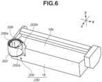
- Fig. 6 is a perspective view of the development container 230. In Fig. 6 , a lever 201 of the replenishment portion 200 and some portions associated with the lever 201 are omitted.
- the development container 230 includes the containing unit 18 and the replenishment portion 200.
- the replenishment portion 200 includes a lever 201, a cylindrical passage portion 202, and a main body shutter 206 (see Fig. 7A ).
- an extending portion 202b extending to the containing unit 18 and a side surface opening 202a connected to the extending portion 202b are formed.
- the replenishment pack 210 is attached to the replenishment portion 200, and toner discharged from the replenishment pack 210 is supplied to the containing unit 18 via an opening 206a on the main body shutter 206 and the side surface opening 202a on the passage portion 202 and the extending portion 202b.
- the extending portion 202b is connected to one end of the containing unit 18 in the longitudinal direction of the development container 230, i.e., the X-direction.
- an agitation member 60 that rotates about a rotary shaft 60a extending in the X-direction is disposed.
- the agitation member 60 includes a blade member 60b fixed to the rotary shaft 60a. Rotation of the agitation member 60 being driven by a motor 311 (see Figs. 15A and 15B ) agitates and levels toner in the containing unit 18 which has been replenished with toner from the replenishment pack 210, and also conveys toner to the development roller 12. While, in the present exemplary embodiment, the agitation member 60 includes the rotary shaft 60a and the blade member 60b, an agitation member having a spiral shape may be used as a component for spreading the toner over the entire length of the containing unit 18.
- the agitation member 60 has the function of circulating toner, which has not been used in development and has been scraped off from the development roller 12, in the containing unit 18 and uniformizing toner in the containing unit 18.
- the agitation member 60 is not limited to a form in which the agitation member 60 rotates.
- an agitation member in a form in which the agitation member swings may be employed.
- Another agitation member may also be further disposed in addition to the agitation member 60.
- a remaining amount detection unit 312 (a toner remaining amount detection unit) for detecting the amount of toner in the containing unit 18 is disposed.
- the remaining amount detection unit 312 includes a light-emitting unit 312a and a light-receiving unit 312b.
- the light-emitting unit 312a and the light-receiving unit 312b are disposed next to each other in the X-direction. Light emitted from the light-emitting unit 312a passes through the inside of the containing unit 18 and is received by the light-receiving unit 312b.
- the light-emitting unit 312a and the light-receiving unit 312b form an optical path Q1 inside the containing unit 18.
- the optical path Q1 extends in the X-direction.
- a light-emitting element and a light-receiving element respectively, may be placed inside the containing unit 18, or the light-emitting element and the light-receiving element, respectively, may be placed outside the containing unit 18, and a light-guiding portion may guide light to the inside and outside of the containing unit 18.
- the light-emitting unit 312a and the light-receiving unit 312b are disposed in a center portion of the containing unit 18 in the X-direction. More specifically, the light-emitting unit 312a and the light-receiving unit 312b are disposed within an area corresponding to a laser passing space SP in the X-direction. Disposing the light-emitting unit 312a and the light-receiving unit 312b in this way in the center portion of the containing unit 18 allows the remaining amount of toner in the containing unit 18 to be excellently detected. More specifically, because a developer (toner) may unevenly gather at end portions of the containing unit 18 in the X-direction while the developer less unevenly gathers at the center portion of the containing unit 18, the actual remaining amount of toner can be detected.
- an LED is used as the light-emitting unit 312a
- a phototransistor that enters an on state by light from the LED is used as the light-receiving unit 312b
- the configuration is not limited to this.
- a halogen lamp or a fluorescent light may be applied to the light-emitting unit 312a
- a photodiode or an avalanche photodiode may be applied to the light-receiving unit 312b.
- the light-receiving unit 312b that is a phototransistor receives light emitted from the light-emitting unit 312a and outputs a signal (a current) according to the amount of the received light.
- the signal is converted into a voltage, and the voltage is input to a control unit 302 (see Figs. 15A and 15B ). That is, the light-receiving unit 312b changes the output value based on the amount of toner (developer) stored in the containing unit 18.
- the control unit 302 determines whether the light-receiving unit 312b has received light from the light-emitting unit 312a. Based on lengths of time in which the light-receiving unit 312b has detected beams of light when the agitation member 60 agitates toner in the containing unit 18 for a certain time, the control unit 302 calculates the amount of toner (the amount of developer) in the containing unit 18. More specifically, a read-only memory (ROM) 302b of the control unit 302 in Fig. 15A stores in advance a table to be used for outputting the remaining amount of toner based on the light reception time when toner is conveyed by the agitation member 60. The control unit 302 predicts and calculates the remaining amount of toner based on the table.
- ROM read-only memory
- the optical path Q1 of the remaining amount detection unit 312 is set to overlap a rotation trajectory TC of the agitation member 60 when viewed in the axis direction of the rotary shaft of the agitation member 60.
- light emitted from the light-emitting unit 312a of the remaining amount detection unit 312 passes through the inside of the containing unit 18 within the rotation trajectory TC of the agitation member 60 when viewed in the axis direction of the agitation member 60.
- the time in which the optical path Q1 is shielded from light by toner conveyed by the agitation member 60 when the agitation member 60 rotates once i.e., the time in which the light-receiving unit 312b does not detect light from the light-emitting unit 312a, changes depending on the remaining amount of toner.
- the control unit 302 can determine the level of the remaining amount of toner in the containing unit 18.
- FIGs. 7A and 7B are perspective views of the replenishment portion 200 as viewed in the same direction.
- Fig. 7C is a perspective view of the replenishment portion 200 as viewed from an angle different from that in Fig. 7A .
- Figs. 8A and 8B are exploded perspective views of the replenishment portion 200.
- the replenishment portion 200 includes the lever 201 (an operation portion), a rotation restriction portion 247, a cover 248, a sealing portion 243, the main body shutter 206, and the passage portion 202.
- the main body shutter 206 is configured to be rotatable about a rotational axis RA with respect to the passage portion 202.
- the main body shutter 206 is disposed inside the passage portion 202 having a tubular form.
- the main body shutter opening 206a is provided in the main body shutter 206.
- the main body shutter 206 also includes a main body shutter engagement portion 206b configured to be engaged with a main body shutter engaged portion 214b of a container shutter 214. If a virtual circle centered on the rotational axis RA is a virtual circle VC, the main body shutter engagement portion 206b is a protruding portion protruding inward in a radial direction r of a virtual circle VC.
- the main body shutter 206 moves (rotates) between the closed position and the opened position by the lever 201 being rotated in the state where the replenishment pack 210 is attached to the replenishment portion 200. That is, the main body shutter 206 moves from the closed position illustrated in Fig. 7A to the closed position illustrated in Fig. 7B by the user rotating the lever 201 by 90 degrees counterclockwise.
- the sealing portion 243 is stuck to the periphery of the main body shutter opening 206a on the inner peripheral surface of the main body shutter 206.
- the sealing portion 243 has a seal opening 243a, and the sealing portion 243 is attached to the main body shutter 206 in such a manner that the seal opening 243a overlaps (communicates with) the main body shutter opening 206a.
- the sealing portion 243 seals a gap between the periphery of an insertion portion opening 212a of an insertion portion 212 of the replenishment pack 210 and the main body shutter 206.
- the rotation restriction portion 247 is disposed inside the main body shutter 206 in the radial direction r of the virtual circle VC.
- the rotation restriction portion 247 includes a rotation restriction portion 247a that restricts the rotation of the insertion portion 212 of the replenishment pack 210 about the rotational axis RA in engagement with a rotation restricted portion 212b of the insertion portion 212.
- the lever 201 includes a ring portion 201a (an annular portion) having an insertion opening 201e into which the insertion portion 212 of the replenishment pack 210 is inserted, and a holding portion 201b disposed integrally with the ring portion 201a.
- the holding portion 201 is a protruding portion protruding outward in the radial direction r of the virtual circle VC from the ring portion 201a.
- the lever 201 includes a lever engagement portion 201d protruding inward in the radial direction r of the virtual circle VC from the inner peripheral surface forming the insertion opening 201e. As illustrated in Fig.
- the cover 248 is a portion that covers the main body shutter opening 206a when the main body shutter 206 is at the closed position.
- the agitation member 60 (see Fig. 4 ) agitates toner in the containing unit 18, and the main body shutter 206 blocks the side surface opening 202a of the passage portion 202 so that toner does not leak from the side surface opening 202a.
- the lever 201 is at an operation position (a first position) illustrated in Fig. 7A so that the main body shutter 206 is at the closed position.
- the side surface opening 202a is required to be opened.
- the lever 201 is at a replenishment position (a second position) illustrated in Fig. 7B so that the main body shutter 206 is at the opened position.
- Figs. 9A and 9B are side views illustrating the lever 201 and a switch 208 (a detection unit).
- the lever 201 includes a detected rib 201c formed integrally with the ring portion 201a.
- the switch 208 as a sensor is disposed below the ring portion 201a.
- the switch 208 is not in contact with the detection rib 201c, and the switch 208 is off.
- the switch 208 is in contact with the detection rib 201c, and the switch 208 is on.
- Turning on and off of the switch 208 is used to detect whether the lever 201 is at the operation position or the replenishment position. That is, in response to the switch 208 switching from the off state to the on state, it can be detected that the lever 201 moves from the operation position to the replenishment position. In response to the switch 208 switching from the off state to the on state, it can be detected that the lever 201 moves from the replenishment position to the operation position.
- FIGS. 11A and 11B and Figs. 12A , 12B , and 12C the configuration of the replenishment pack 210 is described.
- FIGs. 11A and 11B are perspective views of the replenishment pack 210 when viewed from angles different from each other.
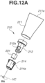
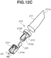
- Figs. 12A , 12B , and 12C are exploded perspective views of the replenishment pack 210 when viewed from angles different from each other.
- the insertion portion opening 212a is covered by the container shutter 214 and actually not seen, and therefore is indicated by a dotted line.
- the replenishment pack 210 includes a pouch 211, an insertion portion 212 (end portion member), the container shutter 214, and a container shutter seal 231.
- the rotational axis RA is a rotational axis about which the container shutter 214 rotates with respect to the insertion portion 212.
- the pouch 211 is a container obtained by pouching a polypropylene sheet into a bag and stores toner inside.
- the pouch 211 is formed such that the thickness tapers down toward the opposite side of the insertion portion 212.
- the pouch 211 includes a pouch end portion 211a extending in a direction orthogonal to the rotational axis RA at its end.
- a pouch is used as a toner storage portion of the replenishment pack 210 in the present exemplary embodiment, a resin bottle or a paper or vinyl container may be used.
- the insertion portion 212 is a tubular portion capable of being inserted into the insertion opening 201e of the lever 201.
- the side surface of the insertion portion 212 extending in the direction of the rotational axis RA has an insertion portion opening 212a.
- the insertion portion 212 is a portion disposed in an end portion of the pouch 211 in the direction of the rotational axis RA and for discharging toner in the pouch 211 to outside the replenishment pack 210 through the insertion portion opening 212a.
- the insertion portion 212 further includes a rotation restricted portion 212b.
- the rotation restricted portion 212b is engaged with the rotation restriction portion 247a of the rotation restriction portion 247 of the replenishment portion 200, to restrict the rotation of the insertion portion 212 about the rotational axis RA.
- the container shutter 214 is a cylindrical member configured to be concentric with the insertion portion 212.
- the container shutter 214 is disposed to be rotatable about the rotational axis RA with respect to the insertion portion 212 outside the insertion portion 212 in the radial direction r of the virtual circle VC and is configured to move (rotate) between a closed position (first closed position) where the insertion portion opening 212a is closed and an opened position (second opened position) where the insertion portion opening 212a is opened.
- a container shutter opening 214c (opening portion) is formed.
- the container shutter opening 214c and the insertion portion opening 212a overlap (communicate with) each other.
- toner can be discharged from the replenishment pack 210 to outside the replenishment pack 210 through the container shutter opening 214c and the insertion portion opening 212a.
- the insertion portion opening 212a is closed by the container shutter 214.
- toner is not discharged from the replenishment pack 210 to outside the replenishment pack 210.
- the container shutter 214 is at the closed position.
- the rotation restricted portion 212b of the insertion portion 212 is exposed through the container shutter opening 214c. This will be described below.
- the main body shutter engaged portion 214b is disposed and is engaged with the lever engagement portion 201d of the lever 201 and the main body shutter engagement portion 206b of the main body shutter 206 when the replenishment pack 210 is attached to the replenishment portion 200.
- the main body shutter engaged portion 214b is a recessed portion recessed inward in the radial direction r of the virtual circle VC from the outer peripheral surface of the container shutter 214 and extends to the end of the container shutter 214 on the side far from the pouch 211 in the direction of the rotational axis RA.
- the container shutter 214 In response to the main body shutter engaged portion 214b receiving a force in a rotational direction about the rotational axis RA from the lever engagement portion 201d of the lever 201, the container shutter 214 is rotated with respect to the insertion portion 212.
- the main body shutter engaged portion 214b does not need to be a recessed portion as long as the container shutter 214 is configured to be rotatable by the rotation of the lever 201 in engagement with the lever 201.
- the container shutter seal 231 is stuck to the inner peripheral surface of the container shutter 214.
- the container shutter seal 231 seals a portion between the periphery of the insertion portion opening 212a of the insertion portion 212 and the container shutter 214.
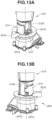
- Figs. 13A and 13B are perspective views of the replenishment portion 200 of the image forming apparatus 1 and the replenishment pack 210 immediately before the replenishment pack 210 is attached to the replenishment portion 200 as viewed from directions different from each other.
- Figs. 13A and 13B when the replenishment pack 210 is attached to the replenishment portion 200 of the image forming apparatus 1, two alignments need to be performed on the replenishment pack 210 with respect to the replenishment portion 200. These alignments are performed in the rotational direction about the rotational axis RA and can be performed in the state where the container shutter 214 is at the closed position.
- Fig. 13A and 13B are perspective views of the replenishment portion 200 of the image forming apparatus 1 and the replenishment pack 210 immediately before the replenishment pack 210 is attached to the replenishment portion 200 as viewed from directions different from each other.
- two alignments need to be performed on the replenishment pack 210 with respect to the replenishment portion 200. These alignments are performed in the rotational direction about the rotational axis
- the first alignment is the alignment between the rotation restricted portion 212b of the insertion portion 212 exposed through the container shutter opening 214c of the container shutter 214 and the rotation restriction portion 247a of the rotation restriction portion 247.
- the second alignment is the alignment between the main body shutter engaged portion 214b and the lever engagement portion 201d.
- the second alignment is successful, this means that the alignment between the main body shutter engaged portion 214b and the main body shutter engagement portion 206b is also successful. This is because the lever engagement portion 201d and the main body shutter engagement portion 206b overlap each other when viewed in the direction of the rotational axis RA.
- the main body shutter engaged portion 214b is engaged with the lever engagement portion 201d and also engaged with the main body shutter engagement portion 206b of the main body shutter 206.
- the rotation restricted portion 212b of the insertion portion 212 is engaged with the rotation restriction portion 247a.
- the user rotates the lever 201 by 90 degrees clockwise by holding the holding portion 201b, whereby the lever 201 is rotated from the first position to the second position with respect to the insertion portion 212.
- the main body shutter engaged portion 214b is pressed by the lever engagement portion 201d, and the container shutter 214 is rotated from the closed position to the opened position with the lever 201.
- the main body shutter engagement portion 206b is pressed by the main body shutter engaged portion 214b, and the main body shutter 206 is rotated from the closed position to the opened position with the lever 201 and the container shutter 214.
- the main body shutter 206 is configured to be rotated via the container shutter 214, which means that the main body shutter 206 does not rotate even in a case where the lever 201 is rotated from the first position to the second position in the state where the replenishment pack 210 is not attached to the replenishment portion 200. More specifically, the main body shutter 206 does not open even if the lever 201 is operated by the user in the state where the replenishment pack 210 is not attached.
- the container shutter 214 and the main body shutter 206 are both at the opened positions, and the container shutter opening 214c and the main body shutter opening 206a communicate with each other.
- the user softens the pouch 211 using their hands as illustrated in Fig. 14 , whereby toner in the pouch 211 moves to the insertion portion 212 with air.
- the toner having moved to the insertion portion 212 passes through the insertion portion opening 212a, the container shutter opening 214c, and the main body shutter opening 206a and is supplied to the containing unit 18 of the development container 230.
- the user rotates the lever 201 by 90 degrees counterclockwise by holding the holding portion 201b.
- the lever 201 is rotated from the second position to the first position with respect to the insertion portion 212.
- the main body shutter engaged portion 214b is pressed by the lever engagement portion 201d, and the container shutter 214 is rotated from the opened position to the closed position with the lever 201.
- the main body shutter engagement portion 206b is pressed by the main body shutter engaged portion 214b, and the main body shutter 206 is rotated from the opened position to the closed position with the lever 201 and the container shutter 214.
- the replenishment pack 210 is detached from the replenishment portion 200 in the state where the lever 201 is at the first position.
- the container shutter 214 is at the closed position.
- toner is prevented from leaking from the insertion portion opening 212a of the replenishment pack 210.
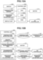
- Fig. 15A is a block diagram illustrating the hardware configuration of the control unit 302 disposed in the image forming apparatus 1.
- the control unit 302 includes a central processing unit (CPU) 302a serving as a calculation device, the ROM 302b, and a random-access memory (RAM) 302c.
- the CPU 302a reads various programs stored in the ROM 302b and executes processing.
- the RAM 302c is used as a work area for the CPU 302a.
- the switch 208 To the input side of the control unit 302, the switch 208, a temperature sensor 9d, and the remaining amount detection unit 312 are connected.
- the temperature sensor 9d detects the temperature of the fixing nip of the fixing unit 9.
- the motor 311 serving as an actuator and a display unit 415 are connected.
- an input/output (I/O) controller 313 serving as an input/output port connected to an external device is also connected.
- the motor 311 drives the agitation member 60 and various rollers (including the photosensitive drum 11, the development roller 12, and various conveyance rollers) in the image forming apparatus 1. While, in the present exemplary embodiment, all the rollers in the image forming apparatus 1 and the agitation member 60 are driven by a single motor 311, the configuration is not limited to this. For example, the agitation member 60 and some of the rollers in the image forming apparatus 1 may be driven by the motor 311, and the other rollers may be driven by another motor. Alternatively, a configuration in which the motor 311 is directly connected to all the rollers via drive transmission members such as gears, and an electromagnetic clutch is disposed between the motor 311 and the agitation member 60 may be employed. In this case, an actuator that turns on and off the driving of the agitation member 60 is the electromagnetic clutch. Alternatively, the actuator may be a solenoid that turns on and off a mechanical clutch disposed between the motor 311 and the agitation member 60.
- Fig. 15B is a block diagram illustrating the functional configuration of the control unit 302 disposed in the image forming apparatus 1.
- the control unit 302 includes a temperature detection unit 303, a driving control unit 304, a transmission/reception unit 305, a remaining amount calculation unit 306, and a storage unit 315.
- the temperature detection unit 303 Based on a temperature detection signal 307 from the temperature sensor 9d, the temperature detection unit 303 detects the current temperature of the fixing unit 9.
- the driving control unit 304 controls the driving of the motor 311 where necessary.
- a driving permission determination unit 314 determines whether to permit driving of the motor 311. For example, in a jam state where the recording material P is jammed in the image forming apparatus 1 or in a breakdown state, the driving permission determination unit 314 does not permit driving of the motor 311. Based on the determination of the driving permission determination unit 314, the driving control unit 304 drives the motor 311.
- the remaining amount calculation unit 306 calculates the amount of toner stored in the containing unit 18.
- the transmission/reception unit 305 transmits and receives information to and from the I/O controller 313 that receives image information from a host, such as a personal computer (PC) (not illustrated).
- the transmission/reception unit 305 transmits particularly the remaining amount of toner stored in the containing unit 18 as remaining amount information 308.
- the remaining amount of toner is transmitted in percentage representation where, for example, the amount of toner that can be stored in the containing unit 18 is 100%.
- the remaining amount detection signal 309 is, for example, an analog signal based on the voltage which changes based on the remaining amount of development, or for example, a pulse signal based on a pulse which is output at constant periods and the H/L pulse width of which changes according to the remaining amount of toner.
- the display unit 415 is disposed on the right side of the front surface of the housing 72 of the image forming apparatus 1 and displays information regarding the remaining amount of toner in the containing unit 18 of the development container 230.
- Figs. 19A, 19B , 19C, and 19D illustrate enlarged views of the display unit 415.
- the display unit 415 is a panel member including a plurality of (three in the present exemplary embodiment) graduations arranged one on top of the other.
- Fig. 19A in a case where only the lower graduation blinks, this indicates that the remaining amount of toner in the containing unit 18 is at a near out level.
- Fig. 19B in a case where only the lower graduation is turned on, this indicates that the remaining amount of toner in the containing unit 18 is at a low level.
- Fig. 19A in a case where only the lower graduation blinks, this indicates that the remaining amount of toner in the containing unit 18 is at a near out level.
- Fig. 19B in a case where only the lower graduation is turned on, this indicates that the remaining amount of toner in the containing unit 18 is at a low level.
- Fig. 19A in a case where only the lower graduation blinks, this
- the display unit 415 is not limited to a liquid crystal panel, and may include a light source, such as an LED or an incandescent light and a diffusion lens. Alternatively, a configuration in which the display unit 415 is not separately provided may be employed, and the remaining amount of toner may be displayed using graduations as described in the present exemplary embodiment on a display of an operation unit. While the display unit 415 according to the present exemplary embodiment includes three graduations, the number of graduations is not limited to this, and may be appropriately set according to the configuration of the image forming apparatus.
- a schematic diagram illustrates thresholds for changing the display of the display unit 415 in accordance with a detection result of the remaining amount of toner in the containing unit 18 of the development container 230 and the display patterns of the display unit 415.
- the display of the display unit 415 is changed based on a result of detection by the remaining amount detection unit 312. Specifically, in a case where the result of detecting the remaining amount of toner in the containing unit 18 by the remaining amount detection unit 312 is greater than or equal to a threshold D (first threshold), the control unit 302 sets the display of the display unit 415 to the full level (first state or first display) where all the three graduations are turned on.
- a threshold D first threshold
- the control unit 302 sets the display of the display unit 415 to the mid level (second state or second display) where the two graduations are turned on.
- the value of the threshold D is set to 5.0 K.
- Various thresholds described below including the threshold D may be appropriately set in accordance with the volume of toner to be supplied or various configurations of the image forming apparatus.
- the control unit 302 sets the display of the display unit 415 to the low level (third state or third display) where the single graduation is turned on. In a case where the result of detecting the remaining amount of toner in the containing unit 18 by the remaining amount detection unit 312 is less than a threshold B (0.5 K in the present exemplary embodiment), the control unit 302 sets the display of the display unit 415 to the near out level (fourth state or fourth display) where the single lower graduation blinks.
- the control unit 302 determines that the toner in the containing unit 18 runs out, and then sets the display of the display unit 415 to a toner out state where all the three graduations are turned off.
- the control unit 302 sets the display of the display unit 415 to the second state. In a case where the result of detecting the remaining amount of toner in the containing unit 18 by the remaining amount detection unit 312 is between 0.5 K and 2.5 K, the control unit 302 sets the display of the display unit 415 to the third state. In a case where the result of detecting the remaining amount of toner in the containing unit 18 by the remaining amount detection unit 312 is between 0 K and 0.5 K, the control unit 302 sets the display of the display unit 415 to the fourth state. If it is determined that there is no remaining amount of toner, the control unit 302 sets the display of the display unit 415 to the state where all the graduations are turned off.
- the interval (the difference) between the amount of toner corresponding to the threshold D and the amount of toner corresponding to the threshold C i.e., the interval (the difference) between the amounts of toner corresponding to thresholds related to the changing of the display of the top graduation
- the interval (the difference) between the amount of toner corresponding to the threshold C and the amount of toner corresponding to the threshold A is also set to the replenishment amount corresponding to a single replenishment pack 210.
- the replenishment mode according to the present exemplary embodiment is started by the opening/closing detection unit detecting that the discharge tray 14 in Fig. 3B has moved from the closed position to the opened position.
- the control unit 302 determines whether the lever 201 is at the replenishment position.
- the replenishment pack 210 is attached to the replenishment portion 200, the lever 201 is rotated from the operation position to the replenishment position, and toner can be supplied from the replenishment pack 210 to the containing unit 18.
- the user softens the pouch 211 of the replenishment pack 210 and replenishes the containing unit 18 with toner from the replenishment pack 210.
- the display unit 415 starts the display of the replenishment mode.
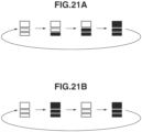
- Figs. 21A and 21B illustrate the display of the replenishment mode on the display unit 415 according to the present exemplary embodiment.
- the display of the replenishment mode is to notify the user that the replenishment mode is being executed.
- Examples of the display of the replenishment mode include a pattern where the state with the three graduations of the display unit 415 being turned on one by one is repeated as illustrated in Fig. 21A , and a pattern where the state with all the three graduations being turned off and being turned on are repeated as illustrated in Fig. 21B .
- the present invention is not limited to these two patterns.
- a pattern where the above first to fourth states of the display unit 415 are randomly changed including a pattern where the state with the three graduations being turned off one by one from the state with all the three graduations being turned on is repeated, is also applicable.
- a configuration in which at least two of the five states including the first to fourth states illustrated in Figs. 19A, 19B , 19C, and 19D and the all-turned-off state where none of the graduations is turned on are repeatedly displayed may be employed. With this configuration, display corresponding to none of the above five states can be performed, which helps the user to visually check that the replenishment mode is currently executed.
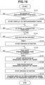
- step S103 the control unit 302 determines whether the lever 201 is at the operation position, based on the detection result of the switch 208. More specifically, the control unit 302 determines whether the lever 201 has been moved from the replenishment position to the operation position. In a case where the determination is YES in step S103, in step S104, the control unit 302 determines whether the motor 311 can be driven. In the state where a printing operation can be performed without delay if the motor 311 is driven, it is determined that the motor 311 can be driven.
- step S104 is necessary. However, in a case where the rollers related to the conveyance of the recording material are not driven, step S 104 may be omitted.
- step S105 the control unit 302 starts the driving of the motor 311.
- the agitation member 60 disposed in the containing unit 18 is driven.
- step S106 the control unit 302 determines whether a first predetermined time has elapsed from when the driving of the motor 311 has been started.
- the first predetermined time is set to three seconds.
- Toner in the containing unit 18 is leveled in three seconds. The leveling of the toner in the containing unit 18 by the agitation member 60 is executed to prepare for the detection of the remaining amount of toner to be executed in the subsequent steps, but may be omitted.
- step S107 the control unit 302 causes the remaining amount detection unit 312 to start the detection of the remaining amount of toner in the containing unit 18 ().
- step S108 the detection of the remaining amount of toner ends, and in step S109, the control unit 302 stops the driving of the motor 311.
- step S 110 the control unit 302 changes the display of the replenishment mode on the display unit 415 to the display of the remaining amount of toner.
- the display of the remaining amount of toner is display reflecting the result of the detection of the remaining amount of toner that has been executed by the remaining amount detection unit 312 between steps S107 and S108.
- the display method according to the detection of the remaining amount of toner is as described above.
- the detection of the remaining amount of toner in step S108 and the driving of the motor 311 in step S109 may be ended at the same time. The above-described steps are executed, and the replenishment mode ends.
- the user may need to perform replenishment work including softening the pouch 211.
- driving sounds are not generated from the motor 311 and gears for driving the agitation member 60 while the user performs the replenishment work, which is effective at preventing the user from hesitating to perform the replenishment work.
- the replenishment pack 210 including the pouch 211 is used.
- the present invention is not limited to this.
- the effects of the present exemplary embodiment can also be obtained by a resin container that pushes toner to outside by the user pushing a plunger into the resin container, or a resin container that discharges toner to outside by the user tapping or squeezing the resin container.
- a second exemplary embodiment of the present invention is described.
- the control in the replenishment mode according to the first exemplary embodiment is modified.
- the configurations of an image forming apparatus 1 and a replenishment pack 210 are similar to those according to the first exemplary embodiment, and the redundant descriptions are omitted.
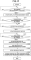
- step S201 the control unit 302 determines whether the lever 201 is at the replenishment position, based on the detection result of the switch 208. In a case where it is determined that the lever 201 is at the replenishment position, in step S202, the display unit 415 starts the display of the replenishment mode.
- the display of the replenishment mode is similar to that in the first exemplary embodiment, and the redundant description is omitted.
- step S203 the control unit 302 determines whether a second predetermined time has elapsed after it has been detected that the lever 201 is at the replenishment position.
- the second predetermined time is 60 seconds.
- the second predetermined time is not limited to 60 seconds.
- the second predetermined time can be any seconds as long as the time is sufficient for detection of movement of the lever 201 from the operation position to the replenishment position, finishing of the replenishment work by the user softening the pouch 211 of the replenishment pack 210 as illustrated in Fig. 14 , and movement of the lever 201 from the replenishment position to the operation position.
- Step S204 to S210 are similar to steps S104 to S110 in the first exemplary embodiment, and the redundant descriptions are omitted.
- the driving of the motor 311 in which driving sounds are generated from the motor 311 and the gears is started after a sufficient time to move the lever 201 from the opened position to the closed position after the user has ended the replenishment work has elapsed. This is effective at preventing the user from hesitating to perform the replenishment work.
- the replenishment pack 210 including the pouch 211 is used, similarly to the first exemplary embodiment, the present invention is not limited to this.
- the second predetermined time may be set to a time sufficient for pushing the plunger into the toner container and rotating the toner container to rotate the container shutter from the opened position to the closed position.
- a third exemplary embodiment of the present invention is described.
- the control in the replenishment mode according to the first exemplary embodiment is modified.
- the configurations of an image forming apparatus 1 and a replenishment pack 210 are similar to those according to the first exemplary embodiment, and the redundant descriptions are omitted.
- step S301 the control unit 302 determines whether the lever 201 is at the replenishment position, based on the detection result of the switch 208. In a case where it is determined that the lever 201 is at the replenishment position, in step S302, the display unit 415 starts the display of the replenishment mode.
- the display of the replenishment mode is similar to that in the first exemplary embodiment, and the redundant description is omitted.
- step S303 the control unit 302 determines whether the motor 311 can be driven.
- step S304 the control unit 302 starts the driving of the motor 311 at a first rotational speed.
- the first rotational speed is a speed that is two-thirds of the rotational speed (a second rotational speed) of the motor 311 in printing on plain paper by the image forming apparatus.
- the rotational speed of the agitation member 60 in rotation of the motor 311 at the first rotational speed is a rotational speed that is two-thirds of rotation of the motor 311 rotating at the second rotational speed.
- step S305 the control unit 302 determines whether the lever 201 is at the operation position, based on the detection result of the switch 208. That is, the control unit 302 determines whether the lever 201 is at the operation position. In a case where it is determined that the lever 201 is at the replenishment position, in step S306, the control unit 302 changes the rotational speed of the motor 311 from the first rotational speed to the second rotational speed faster than the first rotational speed. In step S307, the control unit 302 determines whether a third predetermined time has elapsed from when the rotational speed of the motor 311 has been changed from the first rotational speed to the second rotational speed in step S306. In the present exemplary embodiment, the third predetermined time is set to two seconds.
- Steps S308 to S311 are similar to steps S107 to S 110 in the first exemplary embodiment, and the redundant descriptions are omitted.
- the motor 311 is driven at the first rotational speed lower than the second rotational speed from when the lever 201 is moved from the operation position to the replenishment position to when the lever 201 is moved from the replenishment position to the operation position. Since driving sounds generated from the motor 311 and the gears for driving the agitation member 60 while the user performs the replenishment work on the replenishment pack 210 are small, this configuration is effective at preventing the user from hesitating to perform the replenishment work. Further, since the rotational speed of the motor 311 is increased during a period after the lever 201 on which the user has completed the replenishment work has been moved to the operation position, downtime can be reduced.
- the first rotational speed may be any rotational speed as long as the speed is slower than the second rotational speed.
- the lever 201 is operated in the state where the replenishment pack 210 is attached to the replenishment portion 200, which allows transition between the state where replenishment is possible and the state where replenishment is impossible.
- the present invention is not limited to this.
- a configuration in which the transition between the state where replenishment is possible and the state where replenishment is impossible is performed by rotation of the replenishment pack 210 itself instead of operation on the lever 201 may be employed.
- a configuration in which the container shutter 214 and the main body shutter 206 rotate in conjunction with the rotation of the replenishment pack 210 may be employed.
- the image forming apparatus includes the main body shutter.
- a removable cap may be used instead of the main body shutter.
- a configuration in which the user removes or moves the cap and then attaches the replenishment pack 210 to the replenishment portion 200 may be employed.
Landscapes
- Physics & Mathematics (AREA)
- General Physics & Mathematics (AREA)
- Engineering & Computer Science (AREA)
- Microelectronics & Electronic Packaging (AREA)
- Dry Development In Electrophotography (AREA)
- Control Or Security For Electrophotography (AREA)
Abstract
Description
- The present invention relates to an image forming apparatus that forms an image on a recording material.
- Generally, an electrophotographic image forming apparatus ultimately transfers a toner image formed on a surface of a photosensitive drum to a recording material, to form an image on the recording material. A configuration in which the image forming apparatus is replenished with toner from outside the image forming apparatus is widely employed. Patent literature (PTL) 1 discusses an image forming apparatus in which a toner container storing toner is attached to an attachment portion of the image forming apparatus, and a user softens the toner container to replenish the image forming apparatus with toner from the toner container.
- PTL 1:
Japanese Patent Laid-Open No. 2020-154300 - The present invention is directed to further improving usability related to toner replenishment in the image forming apparatus in patent literature.
- An image forming apparatus to which a toner container is attachable, the toner container storing toner and including an opening portion for toner replenishment and a shutter movable between a closed position where the opening portion is closed and an opened position where the opening portion is opened, the image forming apparatus includes an attachment portion configured to receive attachment of the toner container, a storage portion configured to store toner supplied from the opening portion of the toner container attached to the attachment portion, an agitation member configured to agitate toner in the storage portion, an actuator configured to drive the agitation member; and, a control unit configured to control the actuator, wherein the attachment portion includes an operation portion, including an engagement portion configured to be engaged with the shutter in a state where the toner container is attached to the attachment portion, configured to move with the shutter by the engagement portion being engaged with the shutter, the operation portion being movable between a first position where the shutter is at the closed position and a second position where the shutter is at the opened position, and a detection unit configured to detect a movement of the operation portion, and wherein the control unit controls the actuator in such a manner that driving of the agitation member is started based on detection by the detection unit detecting a movement of the operation portion from the second position to the first position.
- According to the present invention, it is possible to further improve usability related to toner replenishment.
-
- [
Fig. 1] Fig. 1 is a perspective view illustrating an image forming apparatus according to a first exemplary embodiment. - [
Fig. 2] Fig. 2 is a schematic cross-sectional view of the image forming apparatus according to the first exemplary embodiment. - [
Fig. 3A] Fig. 3A is a perspective view illustrating a state where a discharge tray of the image forming apparatus according to the first exemplary embodiment is at a closed position and an opened position. - [
Fig. 3B] Fig. 3B is a perspective view illustrating the state where the discharge tray of the image forming apparatus according to the first exemplary embodiment is at the closed position and the opened position. - [
Fig. 4] Fig. 4 is a cross-sectional view of a development container of the image forming apparatus according to the first exemplary embodiment. - [
Fig. 5] Fig. 5 is a top view of a replenishment portion, a scanner unit, and a photosensitive drum according to the first exemplary embodiment. - [
Fig. 6] Fig. 6 is a perspective view of the development container according to the first exemplary embodiment. - [
Fig. 7A] Fig. 7A is a perspective view of the replenishment portion when a lever is at an operation position and a replenishment position according to the first exemplary embodiment. - [
Fig. 7B] Fig. 7B is a perspective view of the replenishment portion when the lever is at the operation position and the replenishment position according to the first exemplary embodiment. - [
Fig. 7C] Fig. 7C is a perspective view of the replenishment portion when the lever is at the operation position and the replenishment position according to the first exemplary embodiment. - [
Fig. 8A] Fig. 8A is an exploded perspective view of the replenishment portion. - [
Fig. 8B] Fig. 8B is an exploded perspective view of the replenishment portion. - [
Fig. 9A] Fig. 9A is a diagram illustrating a state of a switch when the lever is at the operation position and the replenishment position according to the first exemplary embodiment. - [
Fig. 9B] Fig. 9B is a diagram illustrating a state of a switch when the lever is at the operation position and the replenishment position according to the first exemplary embodiment. - [
Fig. 10] Fig. 10 is a diagram illustrating a position of a holding portion of the lever when the lever is at the operation position and the replenishment position according to the first exemplary embodiment. - [
Fig. 11A] Fig. 11A is a perspective view of a replenishment pack according to the first exemplary embodiment. - [
Fig. 11B] Fig. 11B is a perspective view of the replenishment pack according to the first exemplary embodiment. - [
Fig. 12A] Fig. 12A is an exploded perspective view of the replenishment pack according to the first exemplary embodiment. - [
Fig. 12B] Fig. 12B is an exploded perspective view of the replenishment pack according to the first exemplary embodiment. - [
Fig. 12C] Fig. 12C is an exploded perspective view of the replenishment pack according to the first exemplary embodiment. - [
Fig. 13A] Fig. 13A is a perspective view of the replenishment pack and the replenishment portion immediately before the replenishment pack according to the first exemplary embodiment is attached to the replenishment portion. - [
Fig. 13B] Fig. 13B is a perspective view of the replenishment pack and the replenishment portion immediately before the replenishment pack according to the first exemplary embodiment is attached to the replenishment portion. - [
Fig. 14] Fig. 14 is a diagram illustrating a state where a user softens the replenishment pack according to the first exemplary embodiment. - [
Fig. 15A] Fig. 15A is a control block diagram according to the first exemplary embodiment. - [
Fig. 15B] Fig. 15A is the control block diagram according to the first exemplary embodiment. - [
Fig. 16] Fig. 16 is a diagram illustrating a control flow in a replenishment mode according to the first exemplary embodiment. - [
Fig. 17] Fig. 17 is a diagram illustrating a control flow in a replenishment mode according to a second exemplary embodiment. - [
Fig. 18] Fig. 18 is a diagram illustrating a control flow in a replenishment mode according to a third exemplary embodiment. - [
Fig. 19A] Fig. 19A is a diagram illustrating display of a remaining amount of toner on a display unit of the image forming apparatus according to the first exemplary embodiment. - [
Fig. 19B] Fig. 19B is a diagram illustrating display of the remaining amount of toner on the display unit of the image forming apparatus according to the first exemplary embodiment. - [
Fig. 19C] Fig. 19C is a diagram illustrating display of the remaining amount of toner on the display unit of the image forming apparatus according to the first exemplary embodiment. - [
Fig. 19D] Fig. 19D is a diagram illustrating display of the remaining amount of toner on the display unit of the image forming apparatus according to the first exemplary embodiment. - [
Fig. 20] Fig. 20 is a diagram illustrating relationships between thresholds for changing the display of the remaining amount of toner and an amount of toner in a storage portion according to the first exemplary embodiment. - [
Fig. 21A] Fig. 21A is a diagram illustrating display of the replenishment mode on the display unit according to the first exemplary embodiment. - [
Fig. 21B] Fig. 21B is a diagram illustrating display of the replenishment mode on the display unit according to the first exemplary embodiment. - Exemplary embodiments for carrying out the present invention will be described below with reference to the drawings.
-
Fig. 1 is a perspective view of animage forming apparatus 1 according to a first exemplary embodiment.Fig. 2 is a schematic cross-sectional view of theimage forming apparatus 1. Theimage forming apparatus 1 is a monochrome printer that forms an image on a recording material, based on image information input from an external device. Examples of the recording material include various sheet materials made of different materials, e.g., paper such as plain paper and thick paper, a plastic film such as an overhead projector sheet, sheets having special shapes such as an envelope and index paper, and cloth. - In the following description, the height direction of the image forming apparatus 1 (a direction opposite to the vertical direction) in a case where the
image forming apparatus 1 is installed on a horizontal surface is a Z-direction. A direction intersecting the Z-direction and parallel to a rotational axis direction (a main scanning direction) of aphotosensitive drum 11 is an X-direction. A direction intersecting the X-direction and the Z-direction is a Y-direction. It is desirable that the X-direction, the Y-direction, and the Z-direction should perpendicularly intersect each other. For convenience, the positive side in the X-direction is referred to as a right side, and the negative side in the X-direction is referred to as a left side. The positive side in the Y-direction is referred to as a front side or a front surface side, and the negative side in the Y-direction is referred to as a back side or a back surface side. The positive side in the Z-direction is referred to as an upper side, and the negative side in the Z-direction is referred to as a lower side. - With reference to
Figs. 1 and2 , the overall configuration of theimage forming apparatus 1 is described. As illustrated inFig. 2 , theimage forming apparatus 1 includes animage forming unit 20 that forms a toner image on the recording material, afeeding unit 30 that feeds the recording material P, a fixing unit 9 that fixes the toner image formed by theimage forming unit 20 to the recording material, and adischarge roller pair 10. - The
image forming unit 20 includes ascanner unit 50, anelectrophotographic process unit 40, and a transfer roller 7 that transfers a toner image formed on aphotosensitive drum 11 of theprocess unit 40 to the recording material P. Theprocess unit 40 includes thephotosensitive drum 11 and acleaning unit 13, a chargingroller 17, adevelopment roller 12, and a containingunit 18 that contains toner, which are placed around thephotosensitive drum 11. Theprocess unit 40 may be screwed to ahousing 72 of theimage forming apparatus 1. A process unit that is removed by a serviceman is also included in theprocess unit 40. - The
photosensitive drum 11 as an image bearing member is a photosensitive member molded into a cylindrical shape. Thephotosensitive drum 11 according to the present exemplary embodiment includes a photosensitive layer formed of a negatively charged organic photosensitive member on a drum-like base molded from aluminum. Thephotosensitive drum 11 as the image bearing member is rotationally driven at a predetermined process speed in a predetermined direction (a direction R inFig. 2 ) by a motor. - The charging
roller 17 comes into contact with thephotosensitive drum 11 with a predetermined pressure contact force and forms a charging portion. An application of a desired charging voltage to the chargingroller 17 by a charging high-voltage power supply uniformly charges the surface of thephotosensitive drum 11 to a predetermined potential. In the present exemplary embodiment, thephotosensitive drum 11 is charged to a negative polarity by the chargingroller 17. - The
scanner unit 50 emits laser light corresponding to image information, which has been input from the external device to thephotosensitive drum 11, by using a polygon mirror to scan and expose the surface of thephotosensitive drum 11. As a result of the exposure, an electrostatic latent image according to the image information is formed on the surface of thephotosensitive drum 11. Thescanner unit 50 is not limited to a laser scanner device, and for example, a light-emitting diode (LED) exposure device including an LED array in which a plurality of LEDs is arranged in the longitudinal direction of thephotosensitive drum 11 may be employed. - The
development roller 12 is rotatably supported by the containingunit 18. Thedevelopment roller 12 is disposed in an opening portion of a development container 230 (seeFig. 5 ) including the containingunit 18 in such a manner that thedevelopment roller 12 faces thephotosensitive drum 11. In the containingunit 18, a supply roller for applying toner serving as a developer stored in the containingunit 18 to the surface of thedevelopment roller 12 may be disposed. - The
process unit 40 according to the present exemplary embodiment uses a contact development method as a development method. That is, a toner layer borne on thedevelopment roller 12 comes into contact with thephotosensitive drum 11 in a development portion (a development area) where thephotosensitive drum 11 and thedevelopment roller 12 face each other. A development voltage is applied to thedevelopment roller 12 by a development high-voltage power supply. Because of the development voltage, the toner borne on thedevelopment roller 12 is transferred from thedevelopment roller 12 to the surface of thephotosensitive drum 11 according to the potential distribution of the drum surface, whereby the electrostatic latent image is developed into a toner image. - The toner according to the present exemplary embodiment is a nonmagnetic one-component developer, which is toner that does not contain a magnetic component and is borne on the
development roller 12 mainly by an intermolecular force or an electrostatic force (an image force). Alternatively, a one-component developer containing a magnetic component may be used. Some types of the one-component developer include an additive (e.g., wax or silica microparticles) for adjusting the fluidity or the charging performance of toner in addition to toner particles. Alternatively, a two-component developer composed of nonmagnetic toner and a magnetic carrier may be used as a developer. In a case where a magnetic developer is used, for example, a cylindrical development sleeve inside which a magnet is placed is used as a developer bearing member. - The fixing unit 9 uses a heat fixing method in which the process of fixing an image is performed by heating and fusing the toner on the recording material. The fixing unit 9 includes a
heating roller 9a including a fixing heater 9c, and apressure roller 9b that is in pressure contact with theheating roller 9a. - The
feeding unit 30 includes acassette 4 in which the recording material P is stacked, and a pickup roller 3, a feedingroller 5a, and aseparation roller 5b, which serve as a conveyance unit. In a part of the end surface on the front surface of theimage forming apparatus 1, afront cover 70 is disposed. Thefront cover 70 covers acircuit substrate 100. Thehousing 72 includes thefront cover 70, adischarge tray 14, and anexterior cover 71 forming the exterior of theimage forming apparatus 1 except for thefront cover 70 and thedischarge tray 14. In thehousing 72, adischarge opening 15 through which the sheet to be discharged to thedischarge tray 14 passes is formed. - As illustrated in
Fig. 2 , theimage forming apparatus 1 includes thecircuit substrate 100. Thecircuit substrate 100 includes awiring board 101 made of an insulator andelectronic components wiring board 101. Conductor wiring is disposed on and inside the board of thewiring board 101, and therefore, theelectronic components circuit substrate 100 has the functions of converting an alternating current supplied from outside theimage forming apparatus 1 into a direct current and converting an input voltage to obtain a predetermined voltage value required for an image forming process. - The
circuit substrate 100 is disposed in such a direction that the surface of thewiring board 101 on which theelectronic components wiring board 101 is disposed between thefront cover 70 and thescanner unit 50 in the discharge direction. Theelectronic components wiring board 101 on the side facing thescanner unit 50. - Next, an image forming mode of the
image forming apparatus 1 is described. In an image forming mode according to the present exemplary embodiment, an image is formed on the recording material in the state where thedischarge tray 14 is at a closed position as illustrated inFigs. 1 and3A . In response to an image forming command being input to theimage forming apparatus 1, theimage forming unit 20 starts an image forming process based on image information input from an external computer connected to theimage forming apparatus 1. Thescanner unit 50 emits laser light to thephotosensitive drum 11, based on the input image information. In this process, thephotosensitive drum 11 has been charged by the chargingroller 17, and the irradiation of the laser light forms an electrostatic latent image on thephotosensitive drum 11. Thedevelopment roller 12 develops the electrostatic latent image, and a toner image is formed on thephotosensitive drum 11. - Simultaneously with the above-described image forming process, the pickup roller 3 of the
feeding unit 30 feeds the recording material P supported by thecassette 4. Recording materials P are separated one by one by the feedingroller 5a and theseparation roller 5b, and each recording material P is conveyed to aconveyance roller pair 5c. Then, theconveyance roller pair 5c conveys the recording material P to a transfer nip formed between the transfer roller 7 and thephotosensitive drum 11. - A transfer voltage is applied to the transfer roller 7 by a transfer high-voltage power supply, and the toner image borne on the
photosensitive drum 11 is transferred to the recording material P conveyed by theconveyance roller pair 5c. The recording material P to which the toner image has been transferred is conveyed to the fixing unit 9. When the recording material P passes through a nip portion between theheating roller 9a and thepressure roller 9b of the fixing unit 9, the toner image is heated and pressurized. This fuses toner particles, and the toner particles firmly adhere, whereby the toner image is fixed to the recording material P. The recording material P passed through the fixing unit 9 is discharged through thedischarge opening 15 to outside the image forming apparatus 1 (outside the apparatus) by thedischarge roller pair 10 and stacked on thedischarge tray 14. - In a case where images are formed on both sides of the recording material P, the
discharge roller pair 10 conveys the recording material P, on a first surface of which an image has been formed, in a backward direction to guide the recording material P to a two-sided conveyance path 16. The recording material P guided to the two-sided conveyance path 16 is conveyed toward the transfer roller 7 again by a two-sidedconveyance roller pair 5d. After an image is formed on a second surface of the recording material P by the transfer roller 7, the recording material P is discharged to outside the apparatus by thedischarge roller pair 10. After the transfer of the toner image to the recording material P, toner remaining on thephotosensitive drum 11 is cleaned by thecleaning unit 13. - Next, with reference to
Figs. 3A and 3B toFigs. 7A ,7B , and7C , a replenishment portion 200 (an attachment portion) is described. Thedischarge tray 14 is openably and closably supported to be movable between a closed position where the recording material P can be stacked and the image forming mode can be executed as illustrated inFig. 3A , and an opened position where thedischarge tray 14 is opened as illustrated inFig. 3B . An opening/closing detection unit (not illustrated) can detect at which of the opened position and the closed position thesheet discharge tray 14 is. Thedischarge tray 14 covers thereplenishment portion 200 at the closed position. When thedischarge tray 14 is moved to the opened position, atop surface portion 240 and thereplenishment portion 200 disposed adjacent to thetop surface portion 240 are exposed. Thereplenishment portion 200 is configured such that areplenishment pack 210 is attachable to and detachable from thereplenishment portion 200. Thereplenishment portion 200 is configured such that a user or a serviceman can replenish theimage forming apparatus 1 with toner from outside without removing thedevelopment container 230 from the housing 72 (Fig. 1 ). -
Fig. 4 is a cross-sectional view of thedevelopment container 230 of theimage forming apparatus 1.Fig. 5 is a top view of the image forming apparatus 1 (replenishment portion 200 and scanner unit 50) in the state where the exterior is removed.Fig. 6 is a perspective view of thedevelopment container 230. InFig. 6 , alever 201 of thereplenishment portion 200 and some portions associated with thelever 201 are omitted. - As illustrated in
Figs. 4 to 6 , thedevelopment container 230 includes the containingunit 18 and thereplenishment portion 200. Thereplenishment portion 200 includes alever 201, acylindrical passage portion 202, and a main body shutter 206 (seeFig. 7A ). - In the
passage portion 202, an extendingportion 202b extending to the containingunit 18 and aside surface opening 202a connected to the extendingportion 202b are formed. Thereplenishment pack 210 is attached to thereplenishment portion 200, and toner discharged from thereplenishment pack 210 is supplied to the containingunit 18 via anopening 206a on themain body shutter 206 and theside surface opening 202a on thepassage portion 202 and the extendingportion 202b. - The extending
portion 202b is connected to one end of the containingunit 18 in the longitudinal direction of thedevelopment container 230, i.e., the X-direction. Inside the containingunit 18, as illustrated inFig. 4 , anagitation member 60 that rotates about arotary shaft 60a extending in the X-direction is disposed. Theagitation member 60 includes ablade member 60b fixed to therotary shaft 60a. Rotation of theagitation member 60 being driven by a motor 311 (seeFigs. 15A and 15B ) agitates and levels toner in the containingunit 18 which has been replenished with toner from thereplenishment pack 210, and also conveys toner to thedevelopment roller 12. While, in the present exemplary embodiment, theagitation member 60 includes therotary shaft 60a and theblade member 60b, an agitation member having a spiral shape may be used as a component for spreading the toner over the entire length of the containingunit 18. - The
agitation member 60 has the function of circulating toner, which has not been used in development and has been scraped off from thedevelopment roller 12, in the containingunit 18 and uniformizing toner in the containingunit 18. Theagitation member 60 is not limited to a form in which theagitation member 60 rotates. For example, an agitation member in a form in which the agitation member swings may be employed. Another agitation member may also be further disposed in addition to theagitation member 60. - On a
side surface 18a of the containingunit 18 which is opposite to a side with thedevelopment roller 12, a remaining amount detection unit 312 (a toner remaining amount detection unit) for detecting the amount of toner in the containingunit 18 is disposed. The remainingamount detection unit 312 includes a light-emittingunit 312a and a light-receivingunit 312b. The light-emittingunit 312a and the light-receivingunit 312b are disposed next to each other in the X-direction. Light emitted from the light-emittingunit 312a passes through the inside of the containingunit 18 and is received by the light-receivingunit 312b. That is, the light-emittingunit 312a and the light-receivingunit 312b form an optical path Q1 inside the containingunit 18. The optical path Q1 extends in the X-direction. As the light-emittingunit 312a and the light-receivingunit 312b, a light-emitting element and a light-receiving element, respectively, may be placed inside the containingunit 18, or the light-emitting element and the light-receiving element, respectively, may be placed outside the containingunit 18, and a light-guiding portion may guide light to the inside and outside of the containingunit 18. - Further, the light-emitting
unit 312a and the light-receivingunit 312b are disposed in a center portion of the containingunit 18 in the X-direction. More specifically, the light-emittingunit 312a and the light-receivingunit 312b are disposed within an area corresponding to a laser passing space SP in the X-direction. Disposing the light-emittingunit 312a and the light-receivingunit 312b in this way in the center portion of the containingunit 18 allows the remaining amount of toner in the containingunit 18 to be excellently detected. More specifically, because a developer (toner) may unevenly gather at end portions of the containingunit 18 in the X-direction while the developer less unevenly gathers at the center portion of the containingunit 18, the actual remaining amount of toner can be detected. - While, in the present exemplary embodiment, an LED is used as the light-emitting
unit 312a, and a phototransistor that enters an on state by light from the LED is used as the light-receivingunit 312b, the configuration is not limited to this. For example, a halogen lamp or a fluorescent light may be applied to the light-emittingunit 312a, and a photodiode or an avalanche photodiode may be applied to the light-receivingunit 312b. - The light-receiving
unit 312b that is a phototransistor receives light emitted from the light-emittingunit 312a and outputs a signal (a current) according to the amount of the received light. The signal is converted into a voltage, and the voltage is input to a control unit 302 (seeFigs. 15A and 15B ). That is, the light-receivingunit 312b changes the output value based on the amount of toner (developer) stored in the containingunit 18. - Based on the level of the input voltage, the
control unit 302 determines whether the light-receivingunit 312b has received light from the light-emittingunit 312a. Based on lengths of time in which the light-receivingunit 312b has detected beams of light when theagitation member 60 agitates toner in the containingunit 18 for a certain time, thecontrol unit 302 calculates the amount of toner (the amount of developer) in the containingunit 18. More specifically, a read-only memory (ROM) 302b of thecontrol unit 302 inFig. 15A stores in advance a table to be used for outputting the remaining amount of toner based on the light reception time when toner is conveyed by theagitation member 60. Thecontrol unit 302 predicts and calculates the remaining amount of toner based on the table. - More specifically, as illustrated in
Fig. 4 , the optical path Q1 of the remainingamount detection unit 312 is set to overlap a rotation trajectory TC of theagitation member 60 when viewed in the axis direction of the rotary shaft of theagitation member 60. In other words, light emitted from the light-emittingunit 312a of the remainingamount detection unit 312 passes through the inside of the containingunit 18 within the rotation trajectory TC of theagitation member 60 when viewed in the axis direction of theagitation member 60. The time in which the optical path Q1 is shielded from light by toner conveyed by theagitation member 60 when theagitation member 60 rotates once, i.e., the time in which the light-receivingunit 312b does not detect light from the light-emittingunit 312a, changes depending on the remaining amount of toner. - More specifically, when the remaining amount of toner is great, the optical path Q1 is likely to be blocked by toner, and consequently, the time in which the light-receiving
unit 312b receives light is short. On the other hand, when the remaining amount of toner is small, conversely, the time in which the light-receivingunit 312b receives light is long. Thus, based on the light reception time of the light-receivingunit 312b as described above, thecontrol unit 302 can determine the level of the remaining amount of toner in the containingunit 18. - The method for detecting and estimating the remaining amount of toner is not limited to the above method, and various known methods for detecting and estimating the remaining amount of toner can be employed. For example, the remaining amount of toner may be detected and estimated in such a manner that two or more metal plates or conductive resin sheets extending in the longitudinal direction of the development roller are disposed on an inner wall of the containing
unit 18, and the capacitance between two of the metal plates or conductive resin sheets are measured. Alternatively, a load cell may be disposed to support thedevelopment container 230 from below, and the remaining amount of toner may be calculated based on a weight measured by the load cell. - A description is given of the detailed configuration of the
replenishment portion 200 to which thereplenishment pack 210 is attached.Figs. 7A and 7B are perspective views of thereplenishment portion 200 as viewed in the same direction.Fig. 7C is a perspective view of thereplenishment portion 200 as viewed from an angle different from that inFig. 7A .Figs. 8A and 8B are exploded perspective views of thereplenishment portion 200. - As illustrated in
Figs. 8A and 8B , thereplenishment portion 200 includes the lever 201 (an operation portion), arotation restriction portion 247, acover 248, a sealingportion 243, themain body shutter 206, and thepassage portion 202. - The
main body shutter 206 is configured to be rotatable about a rotational axis RA with respect to thepassage portion 202. Themain body shutter 206 is disposed inside thepassage portion 202 having a tubular form. In themain body shutter 206, the mainbody shutter opening 206a is provided. Themain body shutter 206 also includes a main bodyshutter engagement portion 206b configured to be engaged with a main body shutter engagedportion 214b of acontainer shutter 214. If a virtual circle centered on the rotational axis RA is a virtual circle VC, the main bodyshutter engagement portion 206b is a protruding portion protruding inward in a radial direction r of a virtual circle VC. - In a case where the
main body shutter 206 is at a closed position (a second closed position) illustrated inFig. 7A , the main body shutter opening 206a and theside surface opening 202a (Fig. 8B ) of thepassage portion 202 do not overlap (communicate with) each other. Theside surface opening 202a is blocked by themain body shutter 206, and toner is not discharged to the extendingportion 202b of thepassage portion 202. In a case where themain body shutter 206 is at an opened position (second opened position) illustrated inFig. 7B , the main body shutter opening 206a and the side surface opening 202a of thepassage portion 202 overlap (communicate with) each other. Thus, toner supplied from thereplenishment pack 210 attached to thereplenishment portion 200 can pass through the main body shutter opening 206a and theside surface opening 202a and be discharged to the extendingportion 202b of thepassage portion 202. - Although the details will be described below, the
main body shutter 206 moves (rotates) between the closed position and the opened position by thelever 201 being rotated in the state where thereplenishment pack 210 is attached to thereplenishment portion 200. That is, themain body shutter 206 moves from the closed position illustrated inFig. 7A to the closed position illustrated inFig. 7B by the user rotating thelever 201 by 90 degrees counterclockwise. - The sealing
portion 243 is stuck to the periphery of the main body shutter opening 206a on the inner peripheral surface of themain body shutter 206. The sealingportion 243 has aseal opening 243a, and the sealingportion 243 is attached to themain body shutter 206 in such a manner that theseal opening 243a overlaps (communicates with) the mainbody shutter opening 206a. In a case where themain body shutter 206 is at the opened position, the sealingportion 243 seals a gap between the periphery of aninsertion portion opening 212a of aninsertion portion 212 of thereplenishment pack 210 and themain body shutter 206. - The
rotation restriction portion 247 is disposed inside themain body shutter 206 in the radial direction r of the virtual circle VC. Therotation restriction portion 247 includes arotation restriction portion 247a that restricts the rotation of theinsertion portion 212 of thereplenishment pack 210 about the rotational axis RA in engagement with a rotation restrictedportion 212b of theinsertion portion 212. - The
lever 201 includes aring portion 201a (an annular portion) having an insertion opening 201e into which theinsertion portion 212 of thereplenishment pack 210 is inserted, and a holdingportion 201b disposed integrally with thering portion 201a. The holdingportion 201 is a protruding portion protruding outward in the radial direction r of the virtual circle VC from thering portion 201a. Thelever 201 includes alever engagement portion 201d protruding inward in the radial direction r of the virtual circle VC from the inner peripheral surface forming the insertion opening 201e. As illustrated inFig. 7C , when themain body shutter 206 is at the closed position, thelever engagement portion 201d is in the same phase with the main bodyshutter engagement portion 206b in the circumferential direction of the virtual circle VC. In other words, when themain body shutter 206 is at the closed position, thelever engagement portion 201d overlaps the main bodyshutter engagement portion 206b when viewed in the direction of the rotational axis RA. - As illustrated in
Fig. 7A , thecover 248 is a portion that covers the mainbody shutter opening 206a when themain body shutter 206 is at the closed position. - In image formation on the recording material P, the agitation member 60 (see
Fig. 4 ) agitates toner in the containingunit 18, and themain body shutter 206 blocks the side surface opening 202a of thepassage portion 202 so that toner does not leak from theside surface opening 202a. Thus, in image formation, thelever 201 is at an operation position (a first position) illustrated inFig. 7A so that themain body shutter 206 is at the closed position. On the other hand, in toner replenishment from thereplenishment pack 210 to the containingunit 18, theside surface opening 202a is required to be opened. Thus, in toner replenishment, thelever 201 is at a replenishment position (a second position) illustrated inFig. 7B so that themain body shutter 206 is at the opened position. -
Figs. 9A and 9B are side views illustrating thelever 201 and a switch 208 (a detection unit). As illustrated inFigs. 8A and9A , thelever 201 includes a detectedrib 201c formed integrally with thering portion 201a. Theswitch 208 as a sensor is disposed below thering portion 201a. When thelever 201 is at the operation position, theswitch 208 is not in contact with thedetection rib 201c, and theswitch 208 is off. When thelever 201 is at the replenishment position, theswitch 208 is in contact with thedetection rib 201c, and theswitch 208 is on. - Turning on and off of the
switch 208 is used to detect whether thelever 201 is at the operation position or the replenishment position. That is, in response to theswitch 208 switching from the off state to the on state, it can be detected that thelever 201 moves from the operation position to the replenishment position. In response to theswitch 208 switching from the off state to the on state, it can be detected that thelever 201 moves from the replenishment position to the operation position. - With reference to
Figs. 11A and11B andFigs. 12A ,12B , and12C , the configuration of thereplenishment pack 210 is described.Figs. 11A and11B are perspective views of thereplenishment pack 210 when viewed from angles different from each other.Figs. 12A ,12B , and12C are exploded perspective views of thereplenishment pack 210 when viewed from angles different from each other. Theinsertion portion opening 212a is covered by thecontainer shutter 214 and actually not seen, and therefore is indicated by a dotted line. - As illustrated in
Figs. 11A and11B andFigs. 12A ,12B , and12C , thereplenishment pack 210 includes apouch 211, an insertion portion 212 (end portion member), thecontainer shutter 214, and acontainer shutter seal 231. The rotational axis RA is a rotational axis about which thecontainer shutter 214 rotates with respect to theinsertion portion 212. - The
pouch 211 is a container obtained by pouching a polypropylene sheet into a bag and stores toner inside. Thepouch 211 is formed such that the thickness tapers down toward the opposite side of theinsertion portion 212. Thepouch 211 includes apouch end portion 211a extending in a direction orthogonal to the rotational axis RA at its end. Although a pouch is used as a toner storage portion of thereplenishment pack 210 in the present exemplary embodiment, a resin bottle or a paper or vinyl container may be used. - The
insertion portion 212 is a tubular portion capable of being inserted into the insertion opening 201e of thelever 201. The side surface of theinsertion portion 212 extending in the direction of the rotational axis RA has aninsertion portion opening 212a. Theinsertion portion 212 is a portion disposed in an end portion of thepouch 211 in the direction of the rotational axis RA and for discharging toner in thepouch 211 to outside thereplenishment pack 210 through theinsertion portion opening 212a. Theinsertion portion 212 further includes a rotation restrictedportion 212b. The rotation restrictedportion 212b is engaged with therotation restriction portion 247a of therotation restriction portion 247 of thereplenishment portion 200, to restrict the rotation of theinsertion portion 212 about the rotational axis RA. - The
container shutter 214 is a cylindrical member configured to be concentric with theinsertion portion 212. Thecontainer shutter 214 is disposed to be rotatable about the rotational axis RA with respect to theinsertion portion 212 outside theinsertion portion 212 in the radial direction r of the virtual circle VC and is configured to move (rotate) between a closed position (first closed position) where theinsertion portion opening 212a is closed and an opened position (second opened position) where theinsertion portion opening 212a is opened. In thecontainer shutter 214, a container shutter opening 214c (opening portion) is formed. When thecontainer shutter 214 is at the opened position, thecontainer shutter opening 214c and theinsertion portion opening 212a overlap (communicate with) each other. In this state, toner can be discharged from thereplenishment pack 210 to outside thereplenishment pack 210 through thecontainer shutter opening 214c and theinsertion portion opening 212a. When thecontainer shutter 214 is at the closed position, theinsertion portion opening 212a is closed by thecontainer shutter 214. In this state, toner is not discharged from thereplenishment pack 210 to outside thereplenishment pack 210. When thereplenishment pack 210 is not attached to theimage forming apparatus 1, thecontainer shutter 214 is at the closed position. When thecontainer shutter 214 is at the closed position, the rotation restrictedportion 212b of theinsertion portion 212 is exposed through thecontainer shutter opening 214c. This will be described below. - On the outer peripheral surface of the
container shutter 214, the main body shutter engagedportion 214b is disposed and is engaged with thelever engagement portion 201d of thelever 201 and the main bodyshutter engagement portion 206b of themain body shutter 206 when thereplenishment pack 210 is attached to thereplenishment portion 200. The main body shutter engagedportion 214b is a recessed portion recessed inward in the radial direction r of the virtual circle VC from the outer peripheral surface of thecontainer shutter 214 and extends to the end of thecontainer shutter 214 on the side far from thepouch 211 in the direction of the rotational axis RA. In response to the main body shutter engagedportion 214b receiving a force in a rotational direction about the rotational axis RA from thelever engagement portion 201d of thelever 201, thecontainer shutter 214 is rotated with respect to theinsertion portion 212. The main body shutter engagedportion 214b does not need to be a recessed portion as long as thecontainer shutter 214 is configured to be rotatable by the rotation of thelever 201 in engagement with thelever 201. - The
container shutter seal 231 is stuck to the inner peripheral surface of thecontainer shutter 214. When thecontainer shutter 214 is at the closed position, thecontainer shutter seal 231 seals a portion between the periphery of theinsertion portion opening 212a of theinsertion portion 212 and thecontainer shutter 214. - A description is given of a method for attaching the
replenishment pack 210 to thereplenishment portion 200 and a method for toner replenishment using thereplenishment pack 210. -
Figs. 13A and 13B are perspective views of thereplenishment portion 200 of theimage forming apparatus 1 and thereplenishment pack 210 immediately before thereplenishment pack 210 is attached to thereplenishment portion 200 as viewed from directions different from each other. As illustrated inFigs. 13A and 13B , when thereplenishment pack 210 is attached to thereplenishment portion 200 of theimage forming apparatus 1, two alignments need to be performed on thereplenishment pack 210 with respect to thereplenishment portion 200. These alignments are performed in the rotational direction about the rotational axis RA and can be performed in the state where thecontainer shutter 214 is at the closed position. As illustrated inFig. 13A , the first alignment is the alignment between the rotation restrictedportion 212b of theinsertion portion 212 exposed through the container shutter opening 214c of thecontainer shutter 214 and therotation restriction portion 247a of therotation restriction portion 247. As illustrated inFig. 13B , the second alignment is the alignment between the main body shutter engagedportion 214b and thelever engagement portion 201d. When the second alignment is successful, this means that the alignment between the main body shutter engagedportion 214b and the main bodyshutter engagement portion 206b is also successful. This is because thelever engagement portion 201d and the main bodyshutter engagement portion 206b overlap each other when viewed in the direction of the rotational axis RA. - In the state where the attachment of the
replenishment pack 210 to thereplenishment portion 200 is completed, the main body shutter engagedportion 214b is engaged with thelever engagement portion 201d and also engaged with the main bodyshutter engagement portion 206b of themain body shutter 206. The rotation restrictedportion 212b of theinsertion portion 212 is engaged with therotation restriction portion 247a. In this state, as illustrated inFig. 10 , the user rotates thelever 201 by 90 degrees clockwise by holding the holdingportion 201b, whereby thelever 201 is rotated from the first position to the second position with respect to theinsertion portion 212. In this operation, the main body shutter engagedportion 214b is pressed by thelever engagement portion 201d, and thecontainer shutter 214 is rotated from the closed position to the opened position with thelever 201. The main bodyshutter engagement portion 206b is pressed by the main body shutter engagedportion 214b, and themain body shutter 206 is rotated from the closed position to the opened position with thelever 201 and thecontainer shutter 214. Themain body shutter 206 is configured to be rotated via thecontainer shutter 214, which means that themain body shutter 206 does not rotate even in a case where thelever 201 is rotated from the first position to the second position in the state where thereplenishment pack 210 is not attached to thereplenishment portion 200. More specifically, themain body shutter 206 does not open even if thelever 201 is operated by the user in the state where thereplenishment pack 210 is not attached. - When the
lever 201 is at the second position in the state where thereplenishment pack 210 is attached to thereplenishment portion 200, thecontainer shutter 214 and themain body shutter 206 are both at the opened positions, and thecontainer shutter opening 214c and the mainbody shutter opening 206a communicate with each other. In this state, the user softens thepouch 211 using their hands as illustrated inFig. 14 , whereby toner in thepouch 211 moves to theinsertion portion 212 with air. Then, the toner having moved to theinsertion portion 212 passes through theinsertion portion opening 212a, thecontainer shutter opening 214c, and the main body shutter opening 206a and is supplied to the containingunit 18 of thedevelopment container 230. - In a case where the
replenishment pack 210 is to be detached from thereplenishment portion 200 after completion of the toner replenishment, then as illustrated inFig. 10 , the user rotates thelever 201 by 90 degrees counterclockwise by holding the holdingportion 201b. By this operation, thelever 201 is rotated from the second position to the first position with respect to theinsertion portion 212. In this operation, the main body shutter engagedportion 214b is pressed by thelever engagement portion 201d, and thecontainer shutter 214 is rotated from the opened position to the closed position with thelever 201. The main bodyshutter engagement portion 206b is pressed by the main body shutter engagedportion 214b, and themain body shutter 206 is rotated from the opened position to the closed position with thelever 201 and thecontainer shutter 214. Thereplenishment pack 210 is detached from thereplenishment portion 200 in the state where thelever 201 is at the first position. In the state where thereplenishment pack 210 is detached from thereplenishment portion 200, thecontainer shutter 214 is at the closed position. Thus, toner is prevented from leaking from theinsertion portion opening 212a of thereplenishment pack 210. -
Fig. 15A is a block diagram illustrating the hardware configuration of thecontrol unit 302 disposed in theimage forming apparatus 1. Thecontrol unit 302 includes a central processing unit (CPU) 302a serving as a calculation device, theROM 302b, and a random-access memory (RAM) 302c. TheCPU 302a reads various programs stored in theROM 302b and executes processing. TheRAM 302c is used as a work area for theCPU 302a. - To the input side of the
control unit 302, theswitch 208, atemperature sensor 9d, and the remainingamount detection unit 312 are connected. Thetemperature sensor 9d detects the temperature of the fixing nip of the fixing unit 9. To the output side of thecontrol unit 302, themotor 311 serving as an actuator and adisplay unit 415 are connected. To thecontrol unit 302, an input/output (I/O)controller 313 serving as an input/output port connected to an external device is also connected. - The
motor 311 drives theagitation member 60 and various rollers (including thephotosensitive drum 11, thedevelopment roller 12, and various conveyance rollers) in theimage forming apparatus 1. While, in the present exemplary embodiment, all the rollers in theimage forming apparatus 1 and theagitation member 60 are driven by asingle motor 311, the configuration is not limited to this. For example, theagitation member 60 and some of the rollers in theimage forming apparatus 1 may be driven by themotor 311, and the other rollers may be driven by another motor. Alternatively, a configuration in which themotor 311 is directly connected to all the rollers via drive transmission members such as gears, and an electromagnetic clutch is disposed between themotor 311 and theagitation member 60 may be employed. In this case, an actuator that turns on and off the driving of theagitation member 60 is the electromagnetic clutch. Alternatively, the actuator may be a solenoid that turns on and off a mechanical clutch disposed between themotor 311 and theagitation member 60. -
Fig. 15B is a block diagram illustrating the functional configuration of thecontrol unit 302 disposed in theimage forming apparatus 1. Thecontrol unit 302 includes atemperature detection unit 303, a drivingcontrol unit 304, a transmission/reception unit 305, a remainingamount calculation unit 306, and a storage unit 315. Based on atemperature detection signal 307 from thetemperature sensor 9d, thetemperature detection unit 303 detects the current temperature of the fixing unit 9. Based on a printing operation, initial control or the like in theimage forming apparatus 1, the drivingcontrol unit 304 controls the driving of themotor 311 where necessary. - Based on the state of the
image forming apparatus 1, a drivingpermission determination unit 314 determines whether to permit driving of themotor 311. For example, in a jam state where the recording material P is jammed in theimage forming apparatus 1 or in a breakdown state, the drivingpermission determination unit 314 does not permit driving of themotor 311. Based on the determination of the drivingpermission determination unit 314, the drivingcontrol unit 304 drives themotor 311. - Based on a remaining
amount detection signal 309 output from the remainingamount detection unit 312 disposed in the containingunit 18, the remainingamount calculation unit 306 calculates the amount of toner stored in the containingunit 18. The transmission/reception unit 305 transmits and receives information to and from the I/O controller 313 that receives image information from a host, such as a personal computer (PC) (not illustrated). In the present exemplary embodiment, the transmission/reception unit 305 transmits particularly the remaining amount of toner stored in the containingunit 18 as remainingamount information 308. - The remaining amount of toner is transmitted in percentage representation where, for example, the amount of toner that can be stored in the containing
unit 18 is 100%. Although depending on the configuration of the remainingamount detection unit 312, the remainingamount detection signal 309 is, for example, an analog signal based on the voltage which changes based on the remaining amount of development, or for example, a pulse signal based on a pulse which is output at constant periods and the H/L pulse width of which changes according to the remaining amount of toner. - The display of the remaining amount of toner according to the present exemplary embodiment is described. As illustrated in
Fig. 1 , thedisplay unit 415 is disposed on the right side of the front surface of thehousing 72 of theimage forming apparatus 1 and displays information regarding the remaining amount of toner in the containingunit 18 of thedevelopment container 230. -
Figs. 19A, 19B ,19C, and 19D illustrate enlarged views of thedisplay unit 415. As illustrated inFigs. 19A, 19B ,19C, and 19D , thedisplay unit 415 is a panel member including a plurality of (three in the present exemplary embodiment) graduations arranged one on top of the other. As illustrated inFig. 19A , in a case where only the lower graduation blinks, this indicates that the remaining amount of toner in the containingunit 18 is at a near out level. As illustrated inFig. 19B , in a case where only the lower graduation is turned on, this indicates that the remaining amount of toner in the containingunit 18 is at a low level. As illustrated inFig. 19C , in a case where the lower and middle graduations are turned on and the upper graduation is turned off, this indicates that the remaining amount of toner in the containingunit 18 is at a middle (mid) level. As illustrated inFig. 19D , in a case where all the three graduations are turned on, this indicates that the remaining amount of toner in the containingunit 18 is at a full level. - The
display unit 415 is not limited to a liquid crystal panel, and may include a light source, such as an LED or an incandescent light and a diffusion lens. Alternatively, a configuration in which thedisplay unit 415 is not separately provided may be employed, and the remaining amount of toner may be displayed using graduations as described in the present exemplary embodiment on a display of an operation unit. While thedisplay unit 415 according to the present exemplary embodiment includes three graduations, the number of graduations is not limited to this, and may be appropriately set according to the configuration of the image forming apparatus. - A description is given of the changing of the display of the
display unit 415 according to the present exemplary embodiment. A schematic diagram illustrates thresholds for changing the display of thedisplay unit 415 in accordance with a detection result of the remaining amount of toner in the containingunit 18 of thedevelopment container 230 and the display patterns of thedisplay unit 415. - As illustrated in
Fig. 20 , in response to a change in the remaining amount of toner in the containingunit 18 in accordance with the toner consumption or the toner replenishment in the image forming mode, the display of thedisplay unit 415 is changed based on a result of detection by the remainingamount detection unit 312. Specifically, in a case where the result of detecting the remaining amount of toner in the containingunit 18 by the remainingamount detection unit 312 is greater than or equal to a threshold D (first threshold), thecontrol unit 302 sets the display of thedisplay unit 415 to the full level (first state or first display) where all the three graduations are turned on. In a case where the result of detecting the remaining amount of toner in the containingunit 18 by the remainingamount detection unit 312 is less than the threshold D, thecontrol unit 302 sets the display of thedisplay unit 415 to the mid level (second state or second display) where the two graduations are turned on. In the present exemplary embodiment, the value of the threshold D is set to 5.0 K. Various thresholds described below including the threshold D may be appropriately set in accordance with the volume of toner to be supplied or various configurations of the image forming apparatus. - In a case where the result of detecting the remaining amount of toner in the containing
unit 18 by the remainingamount detection unit 312 is less than a threshold C (2.5 K in the present exemplary embodiment), thecontrol unit 302 sets the display of thedisplay unit 415 to the low level (third state or third display) where the single graduation is turned on. In a case where the result of detecting the remaining amount of toner in the containingunit 18 by the remainingamount detection unit 312 is less than a threshold B (0.5 K in the present exemplary embodiment), thecontrol unit 302 sets the display of thedisplay unit 415 to the near out level (fourth state or fourth display) where the single lower graduation blinks. Then, in a case where the result of detecting the remaining amount of toner in the containingunit 18 by the remainingamount detection unit 312 is less than a threshold A (0 K in the present exemplary embodiment), thecontrol unit 302 determines that the toner in the containingunit 18 runs out, and then sets the display of thedisplay unit 415 to a toner out state where all the three graduations are turned off. - That is, in a case where the result of detecting the remaining amount of toner in the containing
unit 18 by the remainingamount detection unit 312 is between 2.5 K and 5.0 K, thecontrol unit 302 sets the display of thedisplay unit 415 to the second state. In a case where the result of detecting the remaining amount of toner in the containingunit 18 by the remainingamount detection unit 312 is between 0.5 K and 2.5 K, thecontrol unit 302 sets the display of thedisplay unit 415 to the third state. In a case where the result of detecting the remaining amount of toner in the containingunit 18 by the remainingamount detection unit 312 is between 0 K and 0.5 K, thecontrol unit 302 sets the display of thedisplay unit 415 to the fourth state. If it is determined that there is no remaining amount of toner, thecontrol unit 302 sets the display of thedisplay unit 415 to the state where all the graduations are turned off. - The interval (the difference) between the amount of toner corresponding to the threshold D and the amount of toner corresponding to the threshold C, i.e., the interval (the difference) between the amounts of toner corresponding to thresholds related to the changing of the display of the top graduation, according to the present exemplary embodiment is set to the replenishment amount corresponding to a
single replenishment pack 210. Similarly, the interval (the difference) between the amount of toner corresponding to the threshold C and the amount of toner corresponding to the threshold A, i.e., the interval between the amounts of toner corresponding to thresholds related to the changing of the display of the middle graduation, according to the present exemplary embodiment is also set to the replenishment amount corresponding to asingle replenishment pack 210. Setting the intervals between the amounts of toner corresponding to thresholds related to the changing of the display of a graduation in the above-described way helps the user to easily identify the number of replenishment packs 210 to be usable for replenishment. This improves the visibility of the status whether the user performs toner replenishment. - With reference to a control flowchart in
Fig. 16 , a replenishment mode according to the present exemplary embodiment is described. The replenishment mode according to the present exemplary embodiment is started by the opening/closing detection unit detecting that thedischarge tray 14 inFig. 3B has moved from the closed position to the opened position. In a case where the replenishment mode is started, then as illustrated inFig. 16 , in step S101, based on the detection result of theswitch 208, thecontrol unit 302 determines whether thelever 201 is at the replenishment position. In the present exemplary embodiment, as described above, thereplenishment pack 210 is attached to thereplenishment portion 200, thelever 201 is rotated from the operation position to the replenishment position, and toner can be supplied from thereplenishment pack 210 to the containingunit 18. In the state where thelever 201 is at the opened position, the user softens thepouch 211 of thereplenishment pack 210 and replenishes the containingunit 18 with toner from thereplenishment pack 210. After the rotation of thelever 201 from the operation position to the replenishment position has been detected via theswitch 208, in step S102, thedisplay unit 415 starts the display of the replenishment mode. - The display of the replenishment mode on the
display unit 415 in step S102 is described.Figs. 21A and 21B illustrate the display of the replenishment mode on thedisplay unit 415 according to the present exemplary embodiment. The display of the replenishment mode is to notify the user that the replenishment mode is being executed. Examples of the display of the replenishment mode include a pattern where the state with the three graduations of thedisplay unit 415 being turned on one by one is repeated as illustrated inFig. 21A , and a pattern where the state with all the three graduations being turned off and being turned on are repeated as illustrated inFig. 21B . The present invention, however, is not limited to these two patterns. For example, a pattern where the above first to fourth states of thedisplay unit 415 are randomly changed, including a pattern where the state with the three graduations being turned off one by one from the state with all the three graduations being turned on is repeated, is also applicable. As the display of the replenishment mode, a configuration in which at least two of the five states including the first to fourth states illustrated inFigs. 19A, 19B ,19C, and 19D and the all-turned-off state where none of the graduations is turned on are repeatedly displayed may be employed. With this configuration, display corresponding to none of the above five states can be performed, which helps the user to visually check that the replenishment mode is currently executed. - The description returns to the control flowchart in
Fig. 16 . After thedisplay unit 415 has started the display of the replenishment mode in step S102, in step S103, thecontrol unit 302 determines whether thelever 201 is at the operation position, based on the detection result of theswitch 208. More specifically, thecontrol unit 302 determines whether thelever 201 has been moved from the replenishment position to the operation position. In a case where the determination is YES in step S103, in step S104, thecontrol unit 302 determines whether themotor 311 can be driven. In the state where a printing operation can be performed without delay if themotor 311 is driven, it is determined that themotor 311 can be driven. In the state where a jam will be exacerbated if themotor 311 is driven, it is determined that themotor 311 cannot be driven. Also, if a failure occurs in theimage forming apparatus 1, it is determined that themotor 311 cannot be driven. In a case where all the rollers in theimage forming apparatus 1 and theagitation member 60 are driven by thesingle motor 311 as themotor 311 as in the present exemplary embodiment, step S104 is necessary. However, in a case where the rollers related to the conveyance of the recording material are not driven, step S 104 may be omitted. - In a case where the determination is YES in step S104, in step S105, the
control unit 302 starts the driving of themotor 311. In the driving, theagitation member 60 disposed in the containingunit 18 is driven. In step S106, thecontrol unit 302 determines whether a first predetermined time has elapsed from when the driving of themotor 311 has been started. In the present exemplary embodiment, the first predetermined time is set to three seconds. Toner in the containingunit 18 is leveled in three seconds. The leveling of the toner in the containingunit 18 by theagitation member 60 is executed to prepare for the detection of the remaining amount of toner to be executed in the subsequent steps, but may be omitted. - In a case where the determination is YES in step S106, in step S107, the
control unit 302 causes the remainingamount detection unit 312 to start the detection of the remaining amount of toner in the containing unit 18 (). In step S108, the detection of the remaining amount of toner ends, and in step S109, thecontrol unit 302 stops the driving of themotor 311. In step S 110, thecontrol unit 302 changes the display of the replenishment mode on thedisplay unit 415 to the display of the remaining amount of toner. The display of the remaining amount of toner is display reflecting the result of the detection of the remaining amount of toner that has been executed by the remainingamount detection unit 312 between steps S107 and S108. The display method according to the detection of the remaining amount of toner is as described above. The detection of the remaining amount of toner in step S108 and the driving of themotor 311 in step S109 may be ended at the same time. The above-described steps are executed, and the replenishment mode ends. - In a case of using the
replenishment pack 210 according to the present exemplary embodiment, to replenish the containingunit 18 of thedevelopment container 230 with toner from thereplenishment pack 210, the user may need to perform replenishment work including softening thepouch 211. In the replenishment mode according to the present exemplary embodiment, driving sounds are not generated from themotor 311 and gears for driving theagitation member 60 while the user performs the replenishment work, which is effective at preventing the user from hesitating to perform the replenishment work. - In the present exemplary embodiment, the
replenishment pack 210 including thepouch 211 is used. The present invention, however, is not limited to this. For example, the effects of the present exemplary embodiment can also be obtained by a resin container that pushes toner to outside by the user pushing a plunger into the resin container, or a resin container that discharges toner to outside by the user tapping or squeezing the resin container. - A second exemplary embodiment of the present invention is described. In the second exemplary embodiment, the control in the replenishment mode according to the first exemplary embodiment is modified. The configurations of an
image forming apparatus 1 and areplenishment pack 210 are similar to those according to the first exemplary embodiment, and the redundant descriptions are omitted. - With reference to a control flowchart in
Fig. 17 , control in a replenishment mode according to the present exemplary embodiment is described. As illustrated inFig. 17 , in step S201, thecontrol unit 302 determines whether thelever 201 is at the replenishment position, based on the detection result of theswitch 208. In a case where it is determined that thelever 201 is at the replenishment position, in step S202, thedisplay unit 415 starts the display of the replenishment mode. The display of the replenishment mode is similar to that in the first exemplary embodiment, and the redundant description is omitted. - In step S203, the
control unit 302 determines whether a second predetermined time has elapsed after it has been detected that thelever 201 is at the replenishment position. In the present exemplary embodiment, the second predetermined time is 60 seconds. The second predetermined time is not limited to 60 seconds. The second predetermined time can be any seconds as long as the time is sufficient for detection of movement of thelever 201 from the operation position to the replenishment position, finishing of the replenishment work by the user softening thepouch 211 of thereplenishment pack 210 as illustrated inFig. 14 , and movement of thelever 201 from the replenishment position to the operation position. - In a case where the determination is YES in step S203, the
control unit 302 executes steps S204 to S210. Steps S204 to S210 are similar to steps S104 to S110 in the first exemplary embodiment, and the redundant descriptions are omitted. - In the replenishment mode according to the present exemplary embodiment, the driving of the
motor 311 in which driving sounds are generated from themotor 311 and the gears is started after a sufficient time to move thelever 201 from the opened position to the closed position after the user has ended the replenishment work has elapsed. This is effective at preventing the user from hesitating to perform the replenishment work. - While, in the present exemplary embodiment, the
replenishment pack 210 including thepouch 211 is used, similarly to the first exemplary embodiment, the present invention is not limited to this. In a case where a toner container that discharges toner by a plunger being pushed into the toner container is used instead of thereplenishment pack 210, the second predetermined time may be set to a time sufficient for pushing the plunger into the toner container and rotating the toner container to rotate the container shutter from the opened position to the closed position. - A third exemplary embodiment of the present invention is described. In the third exemplary embodiment, the control in the replenishment mode according to the first exemplary embodiment is modified. The configurations of an
image forming apparatus 1 and areplenishment pack 210 are similar to those according to the first exemplary embodiment, and the redundant descriptions are omitted. - With reference to a control flowchart in
Fig. 18 , control in a replenishment mode according to the present exemplary embodiment is described. In step S301, thecontrol unit 302 determines whether thelever 201 is at the replenishment position, based on the detection result of theswitch 208. In a case where it is determined that thelever 201 is at the replenishment position, in step S302, thedisplay unit 415 starts the display of the replenishment mode. The display of the replenishment mode is similar to that in the first exemplary embodiment, and the redundant description is omitted. - In step S303, the
control unit 302 determines whether themotor 311 can be driven. - In a case where the determination is YES in step S303, in step S304, the
control unit 302 starts the driving of themotor 311 at a first rotational speed. The first rotational speed is a speed that is two-thirds of the rotational speed (a second rotational speed) of themotor 311 in printing on plain paper by the image forming apparatus. The rotational speed of theagitation member 60 in rotation of themotor 311 at the first rotational speed is a rotational speed that is two-thirds of rotation of themotor 311 rotating at the second rotational speed. - In step S305, the
control unit 302 determines whether thelever 201 is at the operation position, based on the detection result of theswitch 208. That is, thecontrol unit 302 determines whether thelever 201 is at the operation position. In a case where it is determined that thelever 201 is at the replenishment position, in step S306, thecontrol unit 302 changes the rotational speed of themotor 311 from the first rotational speed to the second rotational speed faster than the first rotational speed. In step S307, thecontrol unit 302 determines whether a third predetermined time has elapsed from when the rotational speed of themotor 311 has been changed from the first rotational speed to the second rotational speed in step S306. In the present exemplary embodiment, the third predetermined time is set to two seconds. Toner in the containingunit 18 is leveled in two seconds. Then, thecontrol unit 302 executes steps S308 to S311. Steps S308 to S311 are similar to steps S107 to S 110 in the first exemplary embodiment, and the redundant descriptions are omitted. - In the control in the replenishment mode according to the present exemplary embodiment, the
motor 311 is driven at the first rotational speed lower than the second rotational speed from when thelever 201 is moved from the operation position to the replenishment position to when thelever 201 is moved from the replenishment position to the operation position. Since driving sounds generated from themotor 311 and the gears for driving theagitation member 60 while the user performs the replenishment work on thereplenishment pack 210 are small, this configuration is effective at preventing the user from hesitating to perform the replenishment work. Further, since the rotational speed of themotor 311 is increased during a period after thelever 201 on which the user has completed the replenishment work has been moved to the operation position, downtime can be reduced. - While, in the present exemplary embodiment, the
replenishment pack 210 including thepouch 211 is used, similarly to the first exemplary embodiment, the present invention is not limited to this. The first rotational speed may be any rotational speed as long as the speed is slower than the second rotational speed. - In each of the first to third exemplary embodiments, the
lever 201 is operated in the state where thereplenishment pack 210 is attached to thereplenishment portion 200, which allows transition between the state where replenishment is possible and the state where replenishment is impossible. The present invention, however, is not limited to this. For example, a configuration in which the transition between the state where replenishment is possible and the state where replenishment is impossible is performed by rotation of thereplenishment pack 210 itself instead of operation on thelever 201 may be employed. More specifically, a configuration in which thecontainer shutter 214 and themain body shutter 206 rotate in conjunction with the rotation of thereplenishment pack 210 may be employed. - The image forming apparatus according to each of the first to third exemplary embodiments includes the main body shutter. Alternatively, a removable cap may be used instead of the main body shutter. A configuration in which the user removes or moves the cap and then attaches the
replenishment pack 210 to thereplenishment portion 200 may be employed. - The present invention is not limited to the above exemplary embodiments, and can be changed and modified in various ways without departing from the spirit and the scope of the present invention. Thus, the following claims are appended to publicize the scope of the present invention.
- The present application claims priority to
Japanese Patent Application No. 2021-124190 filed on July 29, 2021 -
- 1 image forming apparatus
- 18 containing unit
- 60 agitation member
- 200 replenishment portion (attachment portion)
- 201 lever (operation portion)
- 201d lever engagement portion
- 208 switch (detection unit)
- 210 replenishment pack
- 211 pouch
- 212 insertion portion (end portion member)
- 212a insertion portion opening
- 214 container shutter
- 214b main body shutter engaged portion
- 302 control unit
- 302 motor (actuator)
- 312 remaining amount detection unit
Claims (17)
- An image forming apparatus to which a toner container is attachable, the toner container storing toner and including an opening portion for toner replenishment and a shutter movable between a closed position where the opening portion is closed and an opened position where the opening portion is opened, the image forming apparatus comprising:an attachment portion configured to receive attachment of the toner container;a storage portion configured to store toner supplied from the opening portion of the toner container attached to the attachment portion;an agitation member configured to agitate toner in the storage portion;an actuator configured to drive the agitation member; anda control unit configured to control the actuator,wherein the attachment portion includesan operation portion, including an engagement portion configured to be engaged with the shutter in a state where the toner container is attached to the attachment portion, configured to move with the shutter by the engagement portion being engaged with the shutter, the operation portion being movable between a first position where the shutter is at the closed position and a second position where the shutter is at the opened position, anda detection unit configured to detect a movement of the operation portion, and wherein the control unit controls the actuator in such a manner that driving of the agitation member is started based on detection by the detection unit detecting a movement of the operation portion from the second position to the first position.
- The image forming apparatus according to claim 1, wherein driving of the agitation member stops during a period from detection by the detection unit detecting a movement of the operation portion from the first position to the second position until detection by the detection unit detecting the movement of the operation portion from the second position to the first position.
- The image forming apparatus according to claim 1 or 2, further comprising a toner remaining amount detection unit configured to detect an amount of toner stored in the storage portion,
wherein the toner remaining amount detection unit detects the amount of toner after driving of the agitation member has been started based on detection by the detection unit detecting the movement of the operation portion from the second position to the first position, and while the agitation member is being driven. - The image forming apparatus according to claim 3, wherein the toner remaining amount detection unit starts detecting the amount of toner after a first predetermined time has elapsed from when the driving of the agitation member has been started based on detection by the detection unit detecting the movement of the operation portion from the second position to the first position.
- The image forming apparatus according to claim 3 or 4, wherein the control unit controls the actuator in such a manner that driving of the agitation member is stopped after completion of detection of the amount of toner by the toner remaining amount detection unit.
- The image forming apparatus according to any one of claims 3 to 5, further comprising a display unit configured to display a remaining amount of toner in accordance with a result of detection of the amount of toner by the toner remaining amount detection unit,
wherein the control unit controls the display unit in such a manner that display of a replenishment mode different from the display of the remaining amount of toner is started based detection by the detection unit detecting the movement of the operation portion from the first position to the second position, and the control unit changes the display of the replenishment mode to the display of the remaining amount of toner after completion of detection of the amount of toner by the toner remaining amount detection unit. - An image forming apparatus to which a toner container is attachable, the toner container storing toner and including an opening portion for toner replenishment and a shutter movable between a closed position where the opening portion is open chain and an opened position where the opening portion is opened, the image forming apparatus comprising:an attachment portion configured to receive attachment of the toner container;a storage portion configured to store toner supplied from the opening portion of the toner container attached to the attachment portion;an agitation member configured to agitate toner in the storage portion;an actuator configured to drive the agitation member; anda control unit configured to control the actuator,wherein the attachment portion includesan operation portion, including an engagement portion configured to be engaged with the shutter in a state where the toner container is attached to the attachment portion, configured to move with the shutter by the engagement portion being engaged with the shutter, the operation portion being movable between a first position where the shutter is at the closed position and a second position where the shutter is at the opened position, anda detection unit configured to detect a movement of the operation portion, andwherein the control unit controls the actuator in such a manner that driving of the agitation member is started after a predetermined time has elapsed from when the detection unit has detected a movement of the operation portion from the first position to the second position.
- An image forming apparatus to which a toner container is attachable, the toner container storing toner and including an opening portion for toner replenishment and a shutter movable between a closed position where the opening portion is closed and an opened position where the opening portion is opened, the image forming apparatus comprising:an attachment portion configured to receive attachment of the toner container;a storage portion configured to store toner supplied from the opening portion of the toner container attached to the attachment portion;an agitation member configured to agitate toner in the storage portion;an actuator configured to drive the agitation member; anda control unit configured to control the actuator,wherein the attachment portion includesan operation portion, including an engagement portion configured to be engaged with the shutter in a state where the toner container is attached to the attachment portion, configured to move with the shutter by the engagement portion being engaged with the shutter, the operation portion being movable between a first position where the shutter is at the closed position and a second position where the shutter is at the opened position, anda detection unit configured to detect a movement of the operation portion, and wherein driving of the agitation member is started before the detection unit detects a movement of the operation portion from the second position to the first position, and the control unit controls the actuator in such a manner that a driving speed of the agitation member increases based on detection by the detection unit detecting the movement of the operation portion from the second position to the first position.
- An image forming system comprising:a toner container configured to store toner and including a pouch storing toner, an end portion member which is disposed in an end portion of the pouch and has an opening portion for discharging toner in the pouch to outside of the toner container, and a container shutter which includes an engaged portion and is movable relative to the end portion member between a closed position where the opening portion is closed and an opened position where the opening portion is opened; andan image forming apparatus to which the toner container is attachable,wherein the image forming apparatus includesan attachment portion to which the toner container is attachable;a storage portion configured to store the toner supplied from the opening portion of the toner container attached to the attachment portion;an agitation member configured to agitate the toner in the storage portion;an actuator configured to drive the agitation member; anda control unit configured to control the actuator,wherein the attachment portion includesan operation portion, including an engagement portion configured to be engaged with the engaged portion of the container shutter in a state where the toner container is attached to the attachment portion, configured to move with the container shutter by the engagement portion being engaged with the engaged portion of the container shutter, the operation portion being movable between a first position where the container shutter is at the closed position and a second position where the container shutter is at the opened position, anda detection unit configured to detect a movement of the operation portion, andwherein the control unit controls the actuator in such a manner that driving of the agitation member is started based on detection by the detection unit detecting a movement of the operation portion from the second position to the first position.
- The image forming apparatus according to claim 9, wherein the pouch is formed of a polypropylene sheet.
- The image forming apparatus according to claim 9 or 10, wherein in a case where the container shutter is rotated by the operation portion, the pouch does not rotate.
- The image forming apparatus according to any one of claims 1, 7, and 9, wherein the operation portion includes an annular portion and a protruding portion protruding outward in a radial direction of the annular portion from a center of the annular portion.
- An image forming apparatus to which a toner container is attachable, the toner container storing toner and including an opening portion for toner replenishment and a shutter movable between a closed position where the opening portion is closed and an opened position where the opening portion is opened, the image forming apparatus comprising:an attachment portion to which the toner container is attachable;a storage portion configured to store toner supplied from the opening portion of the toner container attached to the attachment portion;an agitation member configured to agitate toner in the storage portion;an actuator configured to drive the agitation member; anda control unit configured to control the actuator,wherein the attachment portion includesan operation portion, including an engagement portion configured to be engaged with the shutter in a state where the toner container is attached to the attachment portion, configured to move with the shutter by the engagement portion being engaged with the shutter, the operation portion being movable between a first position where the shutter is at the closed position and a second position where the shutter is at the opened position, anda detection unit configured to detect whether the operation portion is at the first position, andwherein the control unit controls the actuator in such a manner that driving of the agitation member is started based on detection by the detection unit detecting transition from a state with the operation portion being not at the first position to a state with the operation portion being at the first position.
- The image forming apparatus according to claim 13, further comprising a toner remaining amount detection unit configured to detect an amount of toner stored in the storage portion,
wherein the toner remaining amount detection unit detects the amount of toner after driving of the agitation member has been started based on detection by the detection unit detecting transition from a state with the operation portion being not at the first position to a state with the operation portion being at the first position, and while the agitation member is being driven. - The image forming apparatus according to claim 14, wherein the toner remaining amount detection unit starts detecting the amount of toner after a first predetermined time elapsed from when driving of the agitation member has been started based on detection by the detection unit detecting transition from a state with the operation portion being not at the first position to a state with the operation portion being at the first position.
- The image forming apparatus according to claim 14 or 15, wherein the control unit controls the actuator in such a manner that driving of the agitation member is started after completion of detection of the amount of toner by the toner remaining amount detection unit.
- The image forming apparatus according to any one of claims 14 to 16, further comprising a display unit configured to display a remaining amount of toner in accordance with a result of detection of the amount of toner by the toner remaining amount detection unit,
wherein the control unit controls the display unit in such a manner that display of a replenishment mode different from the display of the remaining amount of toner is started based on detection by the detection unit detecting transition from a state with the operation portion being not at the first position to a state with the operation portion being at the first position, and the control unit changes the display of the replenishment mode to the display of the remaining amount of toner after completion of detection of the amount of toner by the toner remaining amount detection unit.
Applications Claiming Priority (2)
| Application Number | Priority Date | Filing Date | Title |
|---|---|---|---|
| JP2021124190A JP7764158B2 (en) | 2021-07-29 | 2021-07-29 | Image forming device |
| PCT/JP2022/028514 WO2023008340A1 (en) | 2021-07-29 | 2022-07-22 | Image formation device |
Publications (2)
| Publication Number | Publication Date |
|---|---|
| EP4379471A1 true EP4379471A1 (en) | 2024-06-05 |
| EP4379471A4 EP4379471A4 (en) | 2025-08-06 |
Family
ID=85086922
Family Applications (1)
| Application Number | Title | Priority Date | Filing Date |
|---|---|---|---|
| EP22849402.7A Pending EP4379471A4 (en) | 2021-07-29 | 2022-07-22 | IMAGE FORMING DEVICE |
Country Status (5)
| Country | Link |
|---|---|
| US (2) | US12379679B2 (en) |
| EP (1) | EP4379471A4 (en) |
| JP (1) | JP7764158B2 (en) |
| CN (1) | CN117730283A (en) |
| WO (1) | WO2023008340A1 (en) |
Family Cites Families (14)
| Publication number | Priority date | Publication date | Assignee | Title |
|---|---|---|---|---|
| JP2000227704A (en) | 1999-02-08 | 2000-08-15 | Canon Inc | Developer supply device, development device, and image forming apparatus including the same |
| JP2001255727A (en) | 2000-03-09 | 2001-09-21 | Oki Data Corp | A toner cartridge and a printing apparatus to which the toner cartridge is attached. |
| US6332065B1 (en) * | 2000-11-17 | 2001-12-18 | Xerox Corporation | CRU/toner bottle connector assembly |
| JP4014984B2 (en) | 2002-09-20 | 2007-11-28 | 株式会社リコー | Developing device, image forming apparatus |
| JP4710760B2 (en) * | 2006-08-29 | 2011-06-29 | 富士ゼロックス株式会社 | Developer transport device and image forming apparatus |
| JP6665828B2 (en) * | 2017-04-25 | 2020-03-13 | 京セラドキュメントソリューションズ株式会社 | Image forming apparatus, toner container attachable to image forming apparatus |
| JP7006094B2 (en) * | 2017-09-28 | 2022-01-24 | ブラザー工業株式会社 | Image forming device |
| JP7406896B2 (en) | 2018-11-14 | 2023-12-28 | キヤノン株式会社 | Image forming device |
| JP7458828B2 (en) | 2019-03-15 | 2024-04-01 | キヤノン株式会社 | Image forming device |
| JP7458829B2 (en) * | 2019-03-15 | 2024-04-01 | キヤノン株式会社 | image forming device |
| JP7387328B2 (en) | 2019-08-09 | 2023-11-28 | キヤノン株式会社 | Image forming device |
| JP2021060462A (en) * | 2019-10-03 | 2021-04-15 | キヤノン株式会社 | Image forming apparatus |
| JP2021124190A (en) | 2020-02-07 | 2021-08-30 | 日本電産コパル電子株式会社 | Three-way valve |
| JP7527843B2 (en) * | 2020-05-22 | 2024-08-05 | キヤノン株式会社 | Image forming system |
-
2021
- 2021-07-29 JP JP2021124190A patent/JP7764158B2/en active Active
-
2022
- 2022-07-22 CN CN202280052499.3A patent/CN117730283A/en active Pending
- 2022-07-22 WO PCT/JP2022/028514 patent/WO2023008340A1/en not_active Ceased
- 2022-07-22 EP EP22849402.7A patent/EP4379471A4/en active Pending
-
2024
- 2024-01-26 US US18/424,489 patent/US12379679B2/en active Active
-
2025
- 2025-06-18 US US19/242,806 patent/US20250314992A1/en active Pending
Also Published As
| Publication number | Publication date |
|---|---|
| JP7764158B2 (en) | 2025-11-05 |
| WO2023008340A1 (en) | 2023-02-02 |
| EP4379471A4 (en) | 2025-08-06 |
| US12379679B2 (en) | 2025-08-05 |
| US20240231258A1 (en) | 2024-07-11 |
| JP2023019462A (en) | 2023-02-09 |
| CN117730283A (en) | 2024-03-19 |
| US20250314992A1 (en) | 2025-10-09 |
Similar Documents
| Publication | Publication Date | Title |
|---|---|---|
| CN113574467B (en) | imaging equipment | |
| JP7683071B2 (en) | Image forming device | |
| JP7707350B2 (en) | Image forming device | |
| CN113574466B (en) | Image forming apparatus | |
| CN112711178B (en) | Imaging equipment | |
| EP3940459A1 (en) | Image forming device and image forming system | |
| EP3940460A1 (en) | Image forming device | |
| US20250076786A1 (en) | Image forming apparatus and image forming system | |
| CN113574463A (en) | Image forming apparatus | |
| US12332584B2 (en) | Image forming apparatus having toner replenishment | |
| CN113574464A (en) | Imaging apparatus and imaging system | |
| EP4379471A1 (en) | Image formation device | |
| US12429797B2 (en) | Image forming apparatus and image forming system with display of remaining toner amount | |
| JP2022135424A (en) | image forming device | |
| JP2024068015A (en) | Image forming apparatus and image forming system | |
| JP2025092479A (en) | Image forming device |
Legal Events
| Date | Code | Title | Description |
|---|---|---|---|
| STAA | Information on the status of an ep patent application or granted ep patent |
Free format text: STATUS: THE INTERNATIONAL PUBLICATION HAS BEEN MADE |
|
| PUAI | Public reference made under article 153(3) epc to a published international application that has entered the european phase |
Free format text: ORIGINAL CODE: 0009012 |
|
| STAA | Information on the status of an ep patent application or granted ep patent |
Free format text: STATUS: REQUEST FOR EXAMINATION WAS MADE |
|
| 17P | Request for examination filed |
Effective date: 20240229 |
|
| AK | Designated contracting states |
Kind code of ref document: A1 Designated state(s): AL AT BE BG CH CY CZ DE DK EE ES FI FR GB GR HR HU IE IS IT LI LT LU LV MC MK MT NL NO PL PT RO RS SE SI SK SM TR |
|
| DAV | Request for validation of the european patent (deleted) | ||
| DAX | Request for extension of the european patent (deleted) | ||
| A4 | Supplementary search report drawn up and despatched |
Effective date: 20250703 |
|
| RIC1 | Information provided on ipc code assigned before grant |
Ipc: G03G 15/08 20060101AFI20250627BHEP Ipc: G03G 21/00 20060101ALI20250627BHEP Ipc: G03G 21/14 20060101ALI20250627BHEP |