EP4379417B1 - Dual-wavelength phase range finder for improving measurement of vision capture - Google Patents
Dual-wavelength phase range finder for improving measurement of vision capture Download PDFInfo
- Publication number
- EP4379417B1 EP4379417B1 EP23204078.2A EP23204078A EP4379417B1 EP 4379417 B1 EP4379417 B1 EP 4379417B1 EP 23204078 A EP23204078 A EP 23204078A EP 4379417 B1 EP4379417 B1 EP 4379417B1
- Authority
- EP
- European Patent Office
- Prior art keywords
- signal
- frequency
- low
- light signal
- processing device
- Prior art date
- Legal status (The legal status is an assumption and is not a legal conclusion. Google has not performed a legal analysis and makes no representation as to the accuracy of the status listed.)
- Active
Links
Images

Classifications
-
- G—PHYSICS
- G01—MEASURING; TESTING
- G01S—RADIO DIRECTION-FINDING; RADIO NAVIGATION; DETERMINING DISTANCE OR VELOCITY BY USE OF RADIO WAVES; LOCATING OR PRESENCE-DETECTING BY USE OF THE REFLECTION OR RERADIATION OF RADIO WAVES; ANALOGOUS ARRANGEMENTS USING OTHER WAVES
- G01S17/00—Systems using the reflection or reradiation of electromagnetic waves other than radio waves, e.g. lidar systems
- G01S17/02—Systems using the reflection of electromagnetic waves other than radio waves
- G01S17/06—Systems determining position data of a target
- G01S17/08—Systems determining position data of a target for measuring distance only
- G01S17/32—Systems determining position data of a target for measuring distance only using transmission of continuous waves, whether amplitude-, frequency-, or phase-modulated, or unmodulated
- G01S17/34—Systems determining position data of a target for measuring distance only using transmission of continuous waves, whether amplitude-, frequency-, or phase-modulated, or unmodulated using transmission of continuous, frequency-modulated waves while heterodyning the received signal, or a signal derived therefrom, with a locally-generated signal related to the contemporaneously transmitted signal
-
- G—PHYSICS
- G01—MEASURING; TESTING
- G01S—RADIO DIRECTION-FINDING; RADIO NAVIGATION; DETERMINING DISTANCE OR VELOCITY BY USE OF RADIO WAVES; LOCATING OR PRESENCE-DETECTING BY USE OF THE REFLECTION OR RERADIATION OF RADIO WAVES; ANALOGOUS ARRANGEMENTS USING OTHER WAVES
- G01S17/00—Systems using the reflection or reradiation of electromagnetic waves other than radio waves, e.g. lidar systems
- G01S17/02—Systems using the reflection of electromagnetic waves other than radio waves
- G01S17/06—Systems determining position data of a target
- G01S17/08—Systems determining position data of a target for measuring distance only
- G01S17/32—Systems determining position data of a target for measuring distance only using transmission of continuous waves, whether amplitude-, frequency-, or phase-modulated, or unmodulated
- G01S17/36—Systems determining position data of a target for measuring distance only using transmission of continuous waves, whether amplitude-, frequency-, or phase-modulated, or unmodulated with phase comparison between the received signal and the contemporaneously transmitted signal
-
- G—PHYSICS
- G01—MEASURING; TESTING
- G01S—RADIO DIRECTION-FINDING; RADIO NAVIGATION; DETERMINING DISTANCE OR VELOCITY BY USE OF RADIO WAVES; LOCATING OR PRESENCE-DETECTING BY USE OF THE REFLECTION OR RERADIATION OF RADIO WAVES; ANALOGOUS ARRANGEMENTS USING OTHER WAVES
- G01S7/00—Details of systems according to groups G01S13/00, G01S15/00, G01S17/00
- G01S7/48—Details of systems according to groups G01S13/00, G01S15/00, G01S17/00 of systems according to group G01S17/00
- G01S7/481—Constructional features, e.g. arrangements of optical elements
- G01S7/4814—Constructional features, e.g. arrangements of optical elements of transmitters alone
- G01S7/4815—Constructional features, e.g. arrangements of optical elements of transmitters alone using multiple transmitters
-
- G—PHYSICS
- G01—MEASURING; TESTING
- G01S—RADIO DIRECTION-FINDING; RADIO NAVIGATION; DETERMINING DISTANCE OR VELOCITY BY USE OF RADIO WAVES; LOCATING OR PRESENCE-DETECTING BY USE OF THE REFLECTION OR RERADIATION OF RADIO WAVES; ANALOGOUS ARRANGEMENTS USING OTHER WAVES
- G01S7/00—Details of systems according to groups G01S13/00, G01S15/00, G01S17/00
- G01S7/48—Details of systems according to groups G01S13/00, G01S15/00, G01S17/00 of systems according to group G01S17/00
- G01S7/491—Details of non-pulse systems
- G01S7/4911—Transmitters
-
- G—PHYSICS
- G01—MEASURING; TESTING
- G01S—RADIO DIRECTION-FINDING; RADIO NAVIGATION; DETERMINING DISTANCE OR VELOCITY BY USE OF RADIO WAVES; LOCATING OR PRESENCE-DETECTING BY USE OF THE REFLECTION OR RERADIATION OF RADIO WAVES; ANALOGOUS ARRANGEMENTS USING OTHER WAVES
- G01S7/00—Details of systems according to groups G01S13/00, G01S15/00, G01S17/00
- G01S7/48—Details of systems according to groups G01S13/00, G01S15/00, G01S17/00 of systems according to group G01S17/00
- G01S7/491—Details of non-pulse systems
- G01S7/4912—Receivers
- G01S7/4913—Circuits for detection, sampling, integration or read-out
-
- G—PHYSICS
- G01—MEASURING; TESTING
- G01S—RADIO DIRECTION-FINDING; RADIO NAVIGATION; DETERMINING DISTANCE OR VELOCITY BY USE OF RADIO WAVES; LOCATING OR PRESENCE-DETECTING BY USE OF THE REFLECTION OR RERADIATION OF RADIO WAVES; ANALOGOUS ARRANGEMENTS USING OTHER WAVES
- G01S7/00—Details of systems according to groups G01S13/00, G01S15/00, G01S17/00
- G01S7/48—Details of systems according to groups G01S13/00, G01S15/00, G01S17/00 of systems according to group G01S17/00
- G01S7/491—Details of non-pulse systems
- G01S7/4912—Receivers
- G01S7/4917—Receivers superposing optical signals in a photodetector, e.g. optical heterodyne detection
-
- G—PHYSICS
- G01—MEASURING; TESTING
- G01S—RADIO DIRECTION-FINDING; RADIO NAVIGATION; DETERMINING DISTANCE OR VELOCITY BY USE OF RADIO WAVES; LOCATING OR PRESENCE-DETECTING BY USE OF THE REFLECTION OR RERADIATION OF RADIO WAVES; ANALOGOUS ARRANGEMENTS USING OTHER WAVES
- G01S7/00—Details of systems according to groups G01S13/00, G01S15/00, G01S17/00
- G01S7/48—Details of systems according to groups G01S13/00, G01S15/00, G01S17/00 of systems according to group G01S17/00
- G01S7/491—Details of non-pulse systems
- G01S7/493—Extracting wanted echo signals
-
- G—PHYSICS
- G01—MEASURING; TESTING
- G01S—RADIO DIRECTION-FINDING; RADIO NAVIGATION; DETERMINING DISTANCE OR VELOCITY BY USE OF RADIO WAVES; LOCATING OR PRESENCE-DETECTING BY USE OF THE REFLECTION OR RERADIATION OF RADIO WAVES; ANALOGOUS ARRANGEMENTS USING OTHER WAVES
- G01S7/00—Details of systems according to groups G01S13/00, G01S15/00, G01S17/00
- G01S7/48—Details of systems according to groups G01S13/00, G01S15/00, G01S17/00 of systems according to group G01S17/00
- G01S7/51—Display arrangements
Definitions
- the disclosure relates to the field of laser ranging, in particular to a dual-wavelength phase range finder for improving measurement of vision capture.
- Laser-ranging devices are widely used in fields such as architecture and interior decoration due to their high measurement accuracy.
- US2021247495A1 discloses a light emitting module, an optical signal detection unit, an optical system and a laser radar system.
- the light emitting module comprises: a high-frequency modulation signal output unit, which is configured to output at least two preset high-frequency modulation signals with different frequencies; a laser emitting unit, which is connected with the high-frequency modulation signal output unit, and is configured to emit at least two laser beams with different frequencies after being respectively modulated by at least two high-frequency modulation signals with different frequencies; a reference signal emitting unit, which is connected with the high-frequency modulation signal output unit, and is configured to emit at least two reference signals with different frequencies after being respectively modulated by at least two high-frequency modulation signals with different frequencies.
- US20140071432A1 discloses a system and method for a rangefinding instrument incorporating pulse and continuous wave signal generating and processing techniques for increased distance measurement accuracy.
- the use of the former technique effectively solves the ambiguity issues inherent in the latter while allowing for relatively simple circuit implementations.
- a potentially more accurate phase-based distance measurement technique can be utilized which is also completely independent of the maximum range to the target.
- a photoreceiver for a lidar system has a photodetector configured to generate an output current in response to received light.
- a transimpedance amplifier is configured to receive the output current and generate a voltage output corresponding to the output current in response thereto, and a diode circuit has a cathode coupled at a node between the photodetector output and the transimpedance amplifier input.
- a purpose of the disclosure is to provide a dual-wavelength phase range finder for improving measurement of visual capture, and the range finder solves the technical problem of inaccurate measurement in the related art.
- phase range finder according to claim 1 is provided.
- the laser aiming device is added to the dual-wavelength phase range finder, the laser aiming device is configured to emit the visible light signal to the naked eye, and the outer optical path is configured to emit the first invisible light signal for measurement, and thus the measurement can be performed by a dual-wavelength measurement method. Even in a strong light environment, the naked eye of the user can also accurately see whether the visible light is irradiated on the target, and thus the range finder can adapt to measurements in various environments.
- the dual-wavelength phase range finder also improves measurement range, measurement accuracy, and measurement speed, and the dual-wavelength phase range finder solves the problem of large measurement errors in various complex environments.
- a red light ranging scheme on the market has shortcomings including a short measurement range and poor measurement accuracy, and thus it is difficult to be used in outdoor measurement.
- embodiments of the disclosure provide a dual-wavelength phase range finder for improving measurement of visual capture.
- a laser aiming device is added to the dual-wavelength phase range finder, the laser aiming device is configured to emit a visible light signal to the naked eye, and an outer optical path is configured to emit a first invisible light signal for measurement, and thus the measurement can be performed by a dual-wavelength measurement method.
- the naked eye of the user can also accurately see whether the visible light is irradiated on the target, and thus the range finder can adapt to measurements in various environments.
- the dual-wavelength phase range finder also improves measurement range, measurement accuracy, and measurement speed, and the dual-wavelength phase range finder solves the problem of large measurement errors in various complex environments.
- the dual-wavelength phase range finder for improving measurement of visual capture may also be referred to as a laser ranging system.
- the dual-wavelength phase range finder may be applied to an outdoor environment as well as an indoor environment.
- the devices involved in the embodiments of the disclosure are all physical devices, and the connection modes involved are physical connections.
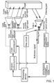
- FIG. 1 illustrates a schematic diagram of a dual-wavelength phase range finder for improving measurement of vision capture provided in an embodiment of the disclosure.
- the dual-wavelength phase range finder includes an emitting device, a receiving device, and a processing device.
- the emitting device may include a frequency synthesizing device, a laser processing device, a laser aiming device configured to aim a target, and an emitting optical system configured to collimate and focus a laser and project the laser on the target.
- the receiving device may include a receiving optical system configured to receive signals diffusely reflected back from the target and focus the signals on a receiver, a filtering device, and a signal-transmitting circuit of the receiving device.
- the signal-transmitting circuit includes a transconductance amplification circuit and a low-frequency bandpass amplification circuit; the transconductance amplification circuit is configured to pre-amplify a first low-frequency signal and a second low-frequency signal demodulated by the receiver to obtain a pre-amplified first low-frequency signal and a pre-amplified second low-frequency signal; and the low-frequency bandpass amplification circuit is configured to amplify the pre-amplified first low-frequency signal and the pre-amplified second low-frequency signal within a preset frequency range to obtain actual phase signals.
- the processing device may control the frequency synthesizing device to generate a high-frequency modulation signal and a reference signal.
- the high-frequency modulation signal passes through the laser processing device to generate a first invisible light signal configured to emit to the target, the first invisible light signal may be collimated and focused by the emitting optical system to project onto the target, and an optical path that the first invisible light signal is emitted from the emitting optical system, irradiated on the target, diffusely reflected to the filtering device, and emitted to the receiver is considered as an outer optical path.
- the frequency synthesizing device may simultaneously generate another invisible optical path with the same frequency as the outer optical path, and the another invisible optical path is directly irradiated to an inner optical path of the receiver through the filtering device.
- the filtering device only allows measurement signals to pass through, and light signals with other wavelengths are blocked by the filtering device (in other words, the filtering device only allows a first reflecting light signal, a second invisible light signal used as a reference, and other measurement signals with long wavelengths to pass through; and the filtering device filters out signals with short wavelengths, such as a second reflecting light signal), i.e., the filtering device is configured to allow the first reflecting light signal and the second invisible light signal to pass through, the first reflecting light signal is obtained by reflecting the first invisible light signal after the first invisible light signal is irradiated onto the target, the filtering device is further configured to block the second reflecting light signal (i.e., block the second reflecting light signal), the second reflecting light signal is obtained by reflecting the visible light signal after the visible light signal is irradiated onto the target, thereby to avoid interference of two wavelengths affecting measurement of a distance.
- the wavelength of the first invisible light signal is equal to the wavelength of the second invisible light signal.
- the processing device While measuring, the processing device also controls the laser aiming device to emit visible light signals or laser signals (such as a green laser, a blue laser, or a red laser) with strong visual impacts, and thus the target can be seen clearly under strong outdoor lights by using the strong visual impacts of light sources.
- visible light signals or laser signals such as a green laser, a blue laser, or a red laser
- the processing device may control the first reflecting light signal and the reference signal to undergo a photoelectric frequency mixing process at the receiver, thereby obtaining the first low-frequency signal used to measure the distance.
- the processing device further controls the second invisible light signal and the reference signal to undergo the photoelectric frequency mixing process at the receiver, thereby obtaining the second low-frequency signal used to measure the distance.
- the first low-frequency signal and the second low-frequency signal are transmitted to the processing device through the transconductance amplification circuit and the low-frequency bandpass amplification circuit for phase discrimination to obtain resultant distance data.
- the processing device uses an existing method to calculate a time difference between the first low-frequency signal amplified by the low-frequency bandpass amplification circuit (i.e., the amplified first low-frequency signal mentioned above) and the second low-frequency signal amplified by the low-frequency bandpass amplification circuit (i.e., the amplified second low-frequency signal mentioned above), and the distance between the dual-wavelength phase range finder and the target is calculated according to the time difference.
- the first low-frequency signal amplified by the low-frequency bandpass amplification circuit i.e., the amplified first low-frequency signal mentioned above
- the second low-frequency signal amplified by the low-frequency bandpass amplification circuit i.e., the amplified second low-frequency signal mentioned above
- the dual-wavelength phase range finder further includes a bias circuit configured to generate and supply a bias voltage to the receiver under control of the processing device, and one end of the bias circuit is connected to the processing device and the other end of the bias circuit is connected to the receiver.
- the dual-wavelength phase range finder further includes a display device configured to display the distance, and the display device is connected to the processing device.
- the wavelength of the visible light signal is in a range of 440 nanometers (nm) to 580 nm.
- the wavelength of the first invisible light signal is greater than 760 nm, and the wavelength of the first invisible light signal is equal to the wavelength of the second invisible light signal.
- FIG. 2 illustrates a schematic diagram of a frequency synthesizing device provided in the embodiment of the disclosure.
- the processing device may control the frequency synthesizing device by a port A and a port B on the frequency synthesizing device, and the processing device controls the frequency synthesizing device to output multiple sets of high-frequency modulation signals TX and reference signals REFERENCE.
- the frequency synthesizing device may be a direct digital synthesizer (DDS) circuit.
- DDS direct digital synthesizer
- Multiple sets of phase-locked loop (PLL) high-frequency oscillation signals are generated by the control of the processing device. In use, a set of PLL high-frequency oscillation signals is selected as the high-frequency modulation signals for output.
- PLL phase-locked loop
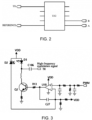
- FIG. 3 illustrates a schematic diagram of a laser processing device provided in the embodiment of the disclosure.
- the laser processing device may include an automatic laser power control circuit, which may include peripheral components such as a laser diode D3, a transistor Q2, and a comparator U18.
- the automatic laser power control circuit is simple, the automatic laser power control circuit may effectively control the automatic laser power and ensure that the laser emission power remains unchanged in an environment of -20 Celsius degrees (°C) ⁇ 60°C, thereby ensuring stable ranging accuracy.
- the laser aiming device may be an existing laser-emitting device
- the processing device controls the laser aiming device to turn on or turn off, thereby controlling whether to emit the visible light.
- the emitting optical system may be an existing emitting optical system, the emitting optical system is configured to ensure that a laser is collimated, focused, and projected onto the target, and the embodiments of the disclosure are not limited to this.
- the receiving optical system may be an existing receiving optical system, and the embodiments of the disclosure are not limited to this.
- the filtering device may be a wavelength filter.
- FIG. 4 illustrates a schematic diagram of a receiver and a transconductance amplification circuit provided in the embodiment of the disclosure.
- the receiver is one of an avalanche photodiode (APD), and a photodiode.
- APD avalanche photodiode
- FIG. 5 illustrates a schematic diagram of a bias circuit provided in the embodiment of the disclosure.
- the bias circuit may include peripheral components such as an inductance L5 and a diode D1.
- the bias circuit changes the frequency control of pulse width modulation (PWM) and analog-to-digital conversion sampling of channel 1 of analog-to-digital converter (ADC1), which can achieve VH-APD voltage output accuracy of 0.1 volts (V).
- PWM pulse width modulation
- ADC1 analog-to-digital conversion sampling of channel 1 of analog-to-digital converter
- V V
- Traditional methods cannot achieve the voltage output accuracy of the disclosure.
- high-precision voltage is supplied to APD to improve the resolution of APD, thereby improving resultant ranging accuracy of the disclosure.
- the transconductance amplification circuit may be an existing transconductance amplification circuit, as long as the transconductance amplification circuit ensures that the signal of the outer optical path (i.e. the first low-frequency signal) and the signal of the inner optical path (i.e. the second low-frequency signal) undergo pre-amplification after demodulation of the receiver, the embodiments of the disclosure are not limited to this.
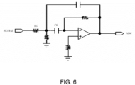
- FIG. 6 illustrates a schematic diagram of a low-frequency bandpass amplification circuit provided in the embodiment of the disclosure.
- the low-frequency bandpass amplification circuit includes peripheral components such as a resistor R6 and a capacitor C6.
- the low-frequency bandpass amplification circuit is further configured to make the pre-amplified signals and reference signal be amplified within a preset frequency range, signals outside the frequency range are blocked, and useful signals are better amplified without distortion, which greatly improves measurement accuracy (also referred to as ranging accuracy) and stability.
- the display device may be a light emitting diode (LED) display screen.
- LED light emitting diode
- the processing device may be a chip or the like. Moreover, the processing device may achieve the phase discrimination of hardware, control various branches, and send the ranging data to the display device. Therefore, the range finder of the disclosure does not require an additional phase discrimination system needed in traditional ranging devices to complete ranging, which greatly reduces costs. The problems existing in production are correspondingly reduced, and the product appearance may be made small and compact.
- the laser aiming device is added to the dual-wavelength phase range finder, and the laser aiming device may emit the visible light signal to the naked eye. Even in a strong light environment, the naked eye of the user can also accurately see whether the visible light is irradiated on the target, and thus the range finder can adapt to measurements in various environments.
- the dual-wavelength phase range finder also improves measurement range, measurement accuracy, and measurement speed, and the dual-wavelength phase range finder solves the problem of large measurement errors in various complex environments.
- a specific structure of the frequency synthesizing device a specific structure of the laser processing device, a specific structure of the laser aiming device, a specific structure of the emitting optical system, a specific structure of the receiving optical system, a specific structure of the filtering device, a specific structure of the receiver, a specific structure of the bias circuit, a specific structure of the transconductance amplification circuit, a specific structure of the low-frequency bandpass amplification circuit, a specific structure of the processing device, and a specific structure of the display device, a specific wavelength of the visible light signal, a specific wavelength of the first invisible light signal, and a specific wavelength of the second invisible light signal may be set according to actual needs.
- the embodiments of the disclosure are not limited to these.
- the terms such as “install”, “connect”, and “fix” should be interpreted in a broad sense.
- the meanings of the terms can be a fixed connection, a detachable connection, an integration, a mechanical connection, or an electrical connection; the meanings of the terms can be a direct connection or indirect connection through an intermediate medium; and the meanings of the terms can be an internal connection of two elements or an interaction relationship between two elements.
- first feature is “above” or “below” a second feature refers to the first and second features can be in direct contact, or the first and second features can be in indirect contact through an intermediate medium.
- first feature is “on”, “above”, or “over” the second feature may mean that that first feature is directly above or obliquely above the second feature, or simply mean that the first feature is higher than the second feature.
- first feature is “under” or “below” the second feature may mean that that first feature is directly below or obliquely below the second feature, or simply mean that the first feature is lower than the second feature.
Landscapes
- Engineering & Computer Science (AREA)
- Physics & Mathematics (AREA)
- Computer Networks & Wireless Communication (AREA)
- General Physics & Mathematics (AREA)
- Radar, Positioning & Navigation (AREA)
- Remote Sensing (AREA)
- Electromagnetism (AREA)
- Optical Radar Systems And Details Thereof (AREA)
Description
- The disclosure relates to the field of laser ranging, in particular to a dual-wavelength phase range finder for improving measurement of vision capture.
- Laser-ranging devices are widely used in fields such as architecture and interior decoration due to their high measurement accuracy.
- However, for traditional laser ranging devices, it is difficult for a naked eye of a user to clearly see whether a laser irradiates a target in a strong light environment, and the ranging to the target may be performed under a condition that the laser does not irradiate the target, thereby resulting in a problem of inaccurate measurement.
-
US2021247495A1 discloses a light emitting module, an optical signal detection unit, an optical system and a laser radar system. The light emitting module comprises: a high-frequency modulation signal output unit, which is configured to output at least two preset high-frequency modulation signals with different frequencies; a laser emitting unit, which is connected with the high-frequency modulation signal output unit, and is configured to emit at least two laser beams with different frequencies after being respectively modulated by at least two high-frequency modulation signals with different frequencies; a reference signal emitting unit, which is connected with the high-frequency modulation signal output unit, and is configured to emit at least two reference signals with different frequencies after being respectively modulated by at least two high-frequency modulation signals with different frequencies. -
US20140071432A1 discloses a system and method for a rangefinding instrument incorporating pulse and continuous wave signal generating and processing techniques for increased distance measurement accuracy. The use of the former technique effectively solves the ambiguity issues inherent in the latter while allowing for relatively simple circuit implementations. Thus, a potentially more accurate phase-based distance measurement technique can be utilized which is also completely independent of the maximum range to the target. -
US2020256961A1 discloses amplifier input protection circuits. In one embodiment, a photoreceiver for a lidar system has a photodetector configured to generate an output current in response to received light. A transimpedance amplifier is configured to receive the output current and generate a voltage output corresponding to the output current in response thereto, and a diode circuit has a cathode coupled at a node between the photodetector output and the transimpedance amplifier input. - In view of the above shortcomings in the related art, a purpose of the disclosure is to provide a dual-wavelength phase range finder for improving measurement of visual capture, and the range finder solves the technical problem of inaccurate measurement in the related art.
- In order to achieve the above purpose, a phase range finder according to claim 1 is provided.
- Therefore, in an embodiment of the disclosure, the laser aiming device is added to the dual-wavelength phase range finder, the laser aiming device is configured to emit the visible light signal to the naked eye, and the outer optical path is configured to emit the first invisible light signal for measurement, and thus the measurement can be performed by a dual-wavelength measurement method. Even in a strong light environment, the naked eye of the user can also accurately see whether the visible light is irradiated on the target, and thus the range finder can adapt to measurements in various environments. The dual-wavelength phase range finder also improves measurement range, measurement accuracy, and measurement speed, and the dual-wavelength phase range finder solves the problem of large measurement errors in various complex environments.
- Additional preferred embodiments are mirrored by the dependent claims.
-
-
FIG. 1 illustrates a schematic diagram of a dual-wavelength phase range finder for improving measurement of vision capture provided in an embodiment of the disclosure. -
FIG. 2 illustrates a schematic diagram of a frequency synthesizing device provided in the embodiment of the disclosure. -
FIG. 3 illustrates a schematic diagram of a laser processing device provided in the embodiment of the disclosure. -
FIG. 4 illustrates a schematic diagram of a receiver and a transconductance amplification circuit provided in the embodiment of the disclosure. -
FIG. 5 illustrates a schematic diagram of a bias circuit provided in the embodiment of the disclosure. -
FIG. 6 illustrates a schematic diagram of a low-frequency bandpass amplification circuit provided in the embodiment of the disclosure. - At present, a red light ranging scheme on the market has shortcomings including a short measurement range and poor measurement accuracy, and thus it is difficult to be used in outdoor measurement.
- In view of the above shortcomings, embodiments of the disclosure provide a dual-wavelength phase range finder for improving measurement of visual capture. A laser aiming device is added to the dual-wavelength phase range finder, the laser aiming device is configured to emit a visible light signal to the naked eye, and an outer optical path is configured to emit a first invisible light signal for measurement, and thus the measurement can be performed by a dual-wavelength measurement method. Even in a strong light environment, the naked eye of the user can also accurately see whether the visible light is irradiated on the target, and thus the range finder can adapt to measurements in various environments. The dual-wavelength phase range finder also improves measurement range, measurement accuracy, and measurement speed, and the dual-wavelength phase range finder solves the problem of large measurement errors in various complex environments.
- It should be understood that the dual-wavelength phase range finder for improving measurement of visual capture may also be referred to as a laser ranging system.
- It should be noted that the dual-wavelength phase range finder may be applied to an outdoor environment as well as an indoor environment.
- In order to understand the above technical solutions clearer, exemplary embodiments of the disclosure will be described in detail below with reference to the drawings. Although the exemplary embodiments of the disclosure are shown in the drawings, it should be understood that the disclosure may be implemented in various forms and should not be limited by the embodiments set forth herein. On the contrary, these embodiments are provided to understand the disclosure clearer and to fully convey the scope of the disclosure to those skilled in the art.
- It should be noted that the devices involved in the embodiments of the disclosure are all physical devices, and the connection modes involved are physical connections.
- Please refer to
FIG. 1, FIG. 1 illustrates a schematic diagram of a dual-wavelength phase range finder for improving measurement of vision capture provided in an embodiment of the disclosure. As shown inFIG. 1 , the dual-wavelength phase range finder includes an emitting device, a receiving device, and a processing device. Specifically, the emitting device may include a frequency synthesizing device, a laser processing device, a laser aiming device configured to aim a target, and an emitting optical system configured to collimate and focus a laser and project the laser on the target. The receiving device may include a receiving optical system configured to receive signals diffusely reflected back from the target and focus the signals on a receiver, a filtering device, and a signal-transmitting circuit of the receiving device. The signal-transmitting circuit includes a transconductance amplification circuit and a low-frequency bandpass amplification circuit; the transconductance amplification circuit is configured to pre-amplify a first low-frequency signal and a second low-frequency signal demodulated by the receiver to obtain a pre-amplified first low-frequency signal and a pre-amplified second low-frequency signal; and the low-frequency bandpass amplification circuit is configured to amplify the pre-amplified first low-frequency signal and the pre-amplified second low-frequency signal within a preset frequency range to obtain actual phase signals. - Specifically, the processing device may control the frequency synthesizing device to generate a high-frequency modulation signal and a reference signal. The high-frequency modulation signal passes through the laser processing device to generate a first invisible light signal configured to emit to the target, the first invisible light signal may be collimated and focused by the emitting optical system to project onto the target, and an optical path that the first invisible light signal is emitted from the emitting optical system, irradiated on the target, diffusely reflected to the filtering device, and emitted to the receiver is considered as an outer optical path. The frequency synthesizing device may simultaneously generate another invisible optical path with the same frequency as the outer optical path, and the another invisible optical path is directly irradiated to an inner optical path of the receiver through the filtering device. The filtering device only allows measurement signals to pass through, and light signals with other wavelengths are blocked by the filtering device (in other words, the filtering device only allows a first reflecting light signal, a second invisible light signal used as a reference, and other measurement signals with long wavelengths to pass through; and the filtering device filters out signals with short wavelengths, such as a second reflecting light signal), i.e., the filtering device is configured to allow the first reflecting light signal and the second invisible light signal to pass through, the first reflecting light signal is obtained by reflecting the first invisible light signal after the first invisible light signal is irradiated onto the target, the filtering device is further configured to block the second reflecting light signal (i.e., block the second reflecting light signal), the second reflecting light signal is obtained by reflecting the visible light signal after the visible light signal is irradiated onto the target, thereby to avoid interference of two wavelengths affecting measurement of a distance. Specifically, the wavelength of the first invisible light signal is equal to the wavelength of the second invisible light signal.
- In addition, While measuring, the processing device also controls the laser aiming device to emit visible light signals or laser signals (such as a green laser, a blue laser, or a red laser) with strong visual impacts, and thus the target can be seen clearly under strong outdoor lights by using the strong visual impacts of light sources.
- Furthermore, the processing device may control the first reflecting light signal and the reference signal to undergo a photoelectric frequency mixing process at the receiver, thereby obtaining the first low-frequency signal used to measure the distance. The processing device further controls the second invisible light signal and the reference signal to undergo the photoelectric frequency mixing process at the receiver, thereby obtaining the second low-frequency signal used to measure the distance. The first low-frequency signal and the second low-frequency signal are transmitted to the processing device through the transconductance amplification circuit and the low-frequency bandpass amplification circuit for phase discrimination to obtain resultant distance data. For example, the processing device uses an existing method to calculate a time difference between the first low-frequency signal amplified by the low-frequency bandpass amplification circuit (i.e., the amplified first low-frequency signal mentioned above) and the second low-frequency signal amplified by the low-frequency bandpass amplification circuit (i.e., the amplified second low-frequency signal mentioned above), and the distance between the dual-wavelength phase range finder and the target is calculated according to the time difference.
- In addition, please refer to
FIG. 1 , the dual-wavelength phase range finder further includes a bias circuit configured to generate and supply a bias voltage to the receiver under control of the processing device, and one end of the bias circuit is connected to the processing device and the other end of the bias circuit is connected to the receiver. - In addition, please refer to
FIG. 1 , the dual-wavelength phase range finder further includes a display device configured to display the distance, and the display device is connected to the processing device. - In an embodiment, the wavelength of the visible light signal is in a range of 440 nanometers (nm) to 580 nm.
- In an embodiment, the wavelength of the first invisible light signal is greater than 760 nm, and the wavelength of the first invisible light signal is equal to the wavelength of the second invisible light signal.
- In an embodiment, please refer to
FIG. 2, FIG. 2 illustrates a schematic diagram of a frequency synthesizing device provided in the embodiment of the disclosure. The processing device may control the frequency synthesizing device by a port A and a port B on the frequency synthesizing device, and the processing device controls the frequency synthesizing device to output multiple sets of high-frequency modulation signals TX and reference signals REFERENCE. - The frequency synthesizing device may be a direct digital synthesizer (DDS) circuit. Multiple sets of phase-locked loop (PLL) high-frequency oscillation signals are generated by the control of the processing device. In use, a set of PLL high-frequency oscillation signals is selected as the high-frequency modulation signals for output.
- In an embodiment, please refer to
FIG. 3, FIG. 3 illustrates a schematic diagram of a laser processing device provided in the embodiment of the disclosure. As shown inFIG. 3 , the laser processing device may include an automatic laser power control circuit, which may include peripheral components such as a laser diode D3, a transistor Q2, and a comparator U18. Furthermore, the automatic laser power control circuit is simple, the automatic laser power control circuit may effectively control the automatic laser power and ensure that the laser emission power remains unchanged in an environment of -20 Celsius degrees (°C)~60°C, thereby ensuring stable ranging accuracy. - In an embodiment, the laser aiming device may be an existing laser-emitting device, the processing device controls the laser aiming device to turn on or turn off, thereby controlling whether to emit the visible light.
- In an embodiment, the emitting optical system may be an existing emitting optical system, the emitting optical system is configured to ensure that a laser is collimated, focused, and projected onto the target, and the embodiments of the disclosure are not limited to this.
- In an embodiment, the receiving optical system may be an existing receiving optical system, and the embodiments of the disclosure are not limited to this.
- In an embodiment, the filtering device may be a wavelength filter.
- In an embodiment, please refer to
FIG. 4, FIG. 4 illustrates a schematic diagram of a receiver and a transconductance amplification circuit provided in the embodiment of the disclosure. As shown inFIG. 4 , the receiver is one of an avalanche photodiode (APD), and a photodiode. - Specifically, when the receiver is APD, the receiver is more sensitive to receive light signals, and the receiver has high gain and low noise, which ensures the ranging accuracy. The transconductance amplification circuit and APD form an optoelectronic frequency mixing circuit configured to demodulate out low-frequency signals.
- In an embodiment, please refer to
FIG. 5, FIG. 5 illustrates a schematic diagram of a bias circuit provided in the embodiment of the disclosure. As shown inFIG. 5 , the bias circuit may include peripheral components such as an inductance L5 and a diode D1. - Moreover, the bias circuit changes the frequency control of pulse width modulation (PWM) and analog-to-digital conversion sampling of channel 1 of analog-to-digital converter (ADC1), which can achieve VH-APD voltage output accuracy of 0.1 volts (V). Traditional methods cannot achieve the voltage output accuracy of the disclosure. Furthermore, high-precision voltage is supplied to APD to improve the resolution of APD, thereby improving resultant ranging accuracy of the disclosure.
- In an embodiment, the transconductance amplification circuit may be an existing transconductance amplification circuit, as long as the transconductance amplification circuit ensures that the signal of the outer optical path (i.e. the first low-frequency signal) and the signal of the inner optical path (i.e. the second low-frequency signal) undergo pre-amplification after demodulation of the receiver, the embodiments of the disclosure are not limited to this.
- In an embodiment, please refer to
FIG. 6, FIG. 6 illustrates a schematic diagram of a low-frequency bandpass amplification circuit provided in the embodiment of the disclosure. The low-frequency bandpass amplification circuit includes peripheral components such as a resistor R6 and a capacitor C6. The low-frequency bandpass amplification circuit is further configured to make the pre-amplified signals and reference signal be amplified within a preset frequency range, signals outside the frequency range are blocked, and useful signals are better amplified without distortion, which greatly improves measurement accuracy (also referred to as ranging accuracy) and stability. - In an embodiment, the display device may be a light emitting diode (LED) display screen.
- In an embodiment, the processing device may be a chip or the like. Moreover, the processing device may achieve the phase discrimination of hardware, control various branches, and send the ranging data to the display device. Therefore, the range finder of the disclosure does not require an additional phase discrimination system needed in traditional ranging devices to complete ranging, which greatly reduces costs. The problems existing in production are correspondingly reduced, and the product appearance may be made small and compact.
- Therefore, based on the above technical solutions, in the embodiments of the disclosure, the laser aiming device is added to the dual-wavelength phase range finder, and the laser aiming device may emit the visible light signal to the naked eye. Even in a strong light environment, the naked eye of the user can also accurately see whether the visible light is irradiated on the target, and thus the range finder can adapt to measurements in various environments. The dual-wavelength phase range finder also improves measurement range, measurement accuracy, and measurement speed, and the dual-wavelength phase range finder solves the problem of large measurement errors in various complex environments.
- It should be understood that a specific structure of the frequency synthesizing device, a specific structure of the laser processing device, a specific structure of the laser aiming device, a specific structure of the emitting optical system, a specific structure of the receiving optical system, a specific structure of the filtering device, a specific structure of the receiver, a specific structure of the bias circuit, a specific structure of the transconductance amplification circuit, a specific structure of the low-frequency bandpass amplification circuit, a specific structure of the processing device, and a specific structure of the display device, a specific wavelength of the visible light signal, a specific wavelength of the first invisible light signal, and a specific wavelength of the second invisible light signal may be set according to actual needs. The embodiments of the disclosure are not limited to these.
- In the description of the disclosure, it should be understood that the terms "first", "second", and the like are only used for a descriptive purpose and cannot be understood as indicating or implying relative importance or implying the number of indicated technical features. Therefore, features limited to "first", "second", and the like can explicitly or implicitly include one or more of these features. In the description of the disclosure, the meaning of "multiple" refers to two or more, unless otherwise specified.
- In the disclosure, unless otherwise specified and defined, the terms such as "install", "connect", and "fix" should be interpreted in a broad sense. For example, the meanings of the terms can be a fixed connection, a detachable connection, an integration, a mechanical connection, or an electrical connection; the meanings of the terms can be a direct connection or indirect connection through an intermediate medium; and the meanings of the terms can be an internal connection of two elements or an interaction relationship between two elements. Those of ordinary skill in the art can understand the specific meanings of the above terms in the disclosure according to specific situations.
- In the disclosure, unless otherwise specified and limited, the meaning of a first feature is "above" or "below" a second feature refers to the first and second features can be in direct contact, or the first and second features can be in indirect contact through an intermediate medium. In addition, the first feature is "on", "above", or "over" the second feature may mean that that first feature is directly above or obliquely above the second feature, or simply mean that the first feature is higher than the second feature. The first feature is "under" or "below" the second feature may mean that that first feature is directly below or obliquely below the second feature, or simply mean that the first feature is lower than the second feature.
-
- TX
- high-frequency modulation signals
- D1
- diode
- D2
- laser diode
- Q2
- transistor
- U18
- comparator
- L5
- inductance
- R6
- resistor
- C6
- capacitor
Claims (10)
- A phase range finder, comprising:an emitting device, a receiving device, and a processing device;wherein the emitting device comprises a frequency synthesizing device, a laser processing device, and a laser aiming device; and the laser processing device is connected between the frequency synthesizing device and the laser aiming device;the processing device is configured to control the frequency synthesizing device to generate a high-frequency modulation signal and a reference signal; the high-frequency modulation signal passes through the laser processing device to define an outer optical path emitted to a target and define an inner optical path emitted to a filtering device of the receiving device, the outer optical path is configured to emit a first invisible light signal, and the inner optical path is configured to emit a second invisible light signal;the receiving device comprises the filtering device, a receiver, and a signal-transmitting circuit;the filtering device is configured to allow a first reflecting light signal and the second invisible light signal to pass through, and the first reflecting light signal is obtained by reflecting the first invisible light signal after the first invisible light signal is irradiated onto the target; the filtering device is further configured to block a second reflecting light signal;the first invisible light signal and the reference signal undergo a photoelectric frequency mixing process at the receiver, thereby causing the processing device to obtain a first low-frequency signal; the second invisible light signal and the reference signal undergo the photoelectric frequency mixing process at the receiver, thereby causing the processing device to obtain a second low-frequency signal; and the first low-frequency signal and the second low-frequency signal pass through the signal-transmitting circuit to obtain an amplified first low-frequency signal and an amplified second low-frequency signal and then are transmitted to the processing device; andthe processing device is configured to determine a distance between the phase range finder and the target;characterized in thatthe processing device is configured to control the laser aiming device to emit a visible light signal for aiming at the target;the second reflecting light signal is obtained by reflecting the visible light signal after the visible light signal is irradiated onto the target;the processing device is specifically configured to control the laser aiming device to be turned on or turned off, to thereby control whether to emit the visible light signal for aiming at the target;the receiver comprises a photodiode;a wavelength of the first invisible light signal is equal to a wavelength of the second invisible light signal; andthe processing device is specifically configured to calculate a time difference of the amplified first low-frequency signal and the amplified second low-frequency signal, to thereby determine the distance between the phase range finder and the target.
- The phase range finder as claimed in claim 1, wherein a wavelength of the visible light signal is smaller than the wavelength of the first invisible light signal.
- The phase range finder as claimed in one of preceding claims, wherein the signal-transmitting circuit comprises a transconductance amplification circuit and a low-frequency bandpass amplification circuit; and
the transconductance amplification circuit is configured to respectively pre-amplify the first low-frequency signal and the second low-frequency signal to obtain a pre-amplified first low-frequency signal and a pre-amplified second low-frequency signal, and transmit the pre-amplified first low-frequency signal and the pre-amplified second low-frequency signal to the low-frequency bandpass amplification circuit; and the low-frequency bandpass amplification circuit is configured to respectively amplify the pre-amplified first low-frequency signal and the pre-amplified second low-frequency signal in a preset frequency range, thereby to obtain the amplified first low-frequency signal and the amplified second low-frequency signal, and transmit the amplified first low-frequency signal and the amplified second low-frequency signal to the processing device. - The phase range finder as claimed in in one of preceding claims, wherein the phase range finder further comprises a bias circuit configured to generate and supply a bias voltage to the receiver under control of the processing device, and a first end of the bias circuit is connected to the processing device and a second end of the bias circuit is connected to the receiver.
- The phase range finder as claimed in one of preceding claims, wherein the phase range finder further comprises a display device configured to display the distance, and the display device is connected to the processing device.
- The phase range finder as claimed in one of preceding claims, wherein the receiver comprises an avalanche photodiode, APD.
- The phase range finder as claimed in claim 6, wherein the frequency synthesizing device comprises a direct digital synthesizer, DDS, circuit.
- The phase range finder as claimed in claim 6 or 7, wherein the laser processing device comprises a laser driving circuit and laser diodes.
- The phase range finder as claimed in one of preceding claims, wherein a color of the visible light signal is one of green, blue, and red.
- The phase range finder as claimed in one of preceding claims, wherein a wavelength of the visible light signal is in a range of 440 nanometers, nm, to 580 nm, and the wavelength of the first invisible light signal and the wavelength of the second invisible light signal are both greater than 760 nm.
Applications Claiming Priority (1)
| Application Number | Priority Date | Filing Date | Title |
|---|---|---|---|
| CN202223208294.6U CN218956802U (en) | 2022-11-30 | 2022-11-30 | Dual-wavelength phase range finder capable of improving measurement vision capture |
Publications (3)
| Publication Number | Publication Date |
|---|---|
| EP4379417A1 EP4379417A1 (en) | 2024-06-05 |
| EP4379417B1 true EP4379417B1 (en) | 2025-05-07 |
| EP4379417C0 EP4379417C0 (en) | 2025-05-07 |
Family
ID=86109044
Family Applications (1)
| Application Number | Title | Priority Date | Filing Date |
|---|---|---|---|
| EP23204078.2A Active EP4379417B1 (en) | 2022-11-30 | 2023-10-17 | Dual-wavelength phase range finder for improving measurement of vision capture |
Country Status (4)
| Country | Link |
|---|---|
| US (1) | US20240175998A1 (en) |
| EP (1) | EP4379417B1 (en) |
| CN (1) | CN218956802U (en) |
| PL (1) | PL4379417T3 (en) |
Families Citing this family (1)
| Publication number | Priority date | Publication date | Assignee | Title |
|---|---|---|---|---|
| CN220137388U (en) * | 2023-05-26 | 2023-12-05 | 深达威科技(广东)股份有限公司 | Three-laser phase distance measuring device |
Family Cites Families (8)
| Publication number | Priority date | Publication date | Assignee | Title |
|---|---|---|---|---|
| CN102540170B (en) * | 2012-02-10 | 2016-02-10 | 江苏徕兹光电科技股份有限公司 | Based on calibration steps and the distance measuring equipment thereof of the phase measurement of dual-wavelength laser pipe |
| US9354051B2 (en) * | 2012-09-13 | 2016-05-31 | Laser Technology, Inc. | System and method for a rangefinding instrument incorporating pulse and continuous wave signal generating and processing techniques for increased distance measurement accuracy |
| CN104035099B (en) * | 2013-03-08 | 2017-02-01 | 江苏徕兹测控科技有限公司 | Dual-transmitting dual-receiving phase measurement-based calibration method and range finding device |
| CN108828615B (en) * | 2018-06-11 | 2024-07-26 | 深圳市镭神智能系统有限公司 | Light emitting unit, optical system, and laser radar system |
| TWI698623B (en) * | 2018-10-15 | 2020-07-11 | 億光電子工業股份有限公司 | Proximity sensing device and display device |
| US11519840B2 (en) * | 2019-01-22 | 2022-12-06 | Ford Global Technologies, Llc | Hydrophobic coating characterization |
| US11774561B2 (en) * | 2019-02-08 | 2023-10-03 | Luminar Technologies, Inc. | Amplifier input protection circuits |
| US12546582B2 (en) * | 2021-06-22 | 2026-02-10 | Duke University | Rapid coherent synthetic wavelength interferometric absolute distance measurement |
-
2022
- 2022-11-30 CN CN202223208294.6U patent/CN218956802U/en active Active
-
2023
- 2023-09-12 US US18/465,178 patent/US20240175998A1/en active Pending
- 2023-10-17 PL PL23204078.2T patent/PL4379417T3/en unknown
- 2023-10-17 EP EP23204078.2A patent/EP4379417B1/en active Active
Also Published As
| Publication number | Publication date |
|---|---|
| US20240175998A1 (en) | 2024-05-30 |
| EP4379417A1 (en) | 2024-06-05 |
| PL4379417T3 (en) | 2025-08-11 |
| CN218956802U (en) | 2023-05-02 |
| EP4379417C0 (en) | 2025-05-07 |
Similar Documents
| Publication | Publication Date | Title |
|---|---|---|
| CN110308456A (en) | It is a kind of for improving the bias adjustment device and laser radar system of detection range | |
| CN111665486B (en) | Laser radar system | |
| CN101581783B (en) | Calibration method and device for phase measurement and distance measuring equipment | |
| CN105319558B (en) | A kind of light energy stabilization control device of phase-shift laser range-finder | |
| US7760337B2 (en) | Optoelectronic distance measuring device | |
| CN1466692A (en) | Apparatus and method for signal detection in a distance measuring device | |
| CA2657677A1 (en) | Optical distance measuring method and corresponding optical distance measurement device | |
| WO2017096957A1 (en) | Calibration method based on single-wavelength and double-laser-tube phase measurement, and device thereof | |
| CN108387902B (en) | Optical ranging method and device | |
| WO2013116963A1 (en) | Calibration method and distance measurement device thereof based on phase measurement of double-wavelength laser tube | |
| US10451715B2 (en) | Using integrated silicon LED to calibrate phase offset in optical receiver in laser range finder | |
| KR20050028921A (en) | Method and device for optically measuring distance | |
| CN109283546B (en) | Phase type laser ranging device and method | |
| CN107450081A (en) | A kind of zero blind area range-measurement system | |
| US20230288538A1 (en) | Laser receiving system and laser ranging system | |
| CN114428239A (en) | Laser radar, method for acquiring flight time of laser radar, method for measuring distance of laser radar, and storage medium | |
| CN106646502A (en) | Novel laser ranging device and method | |
| CN110927737A (en) | A multi-frequency modulation laser dynamic target ranging and speed measuring system and method | |
| US20020131034A1 (en) | High precision laser range finder with an automatic peak control loop | |
| CN116679310A (en) | FMCW laser measuring device | |
| EP4379417A1 (en) | Dual-wavelength phase range finder for improving measurement of vision capture | |
| US20100283990A1 (en) | Optoelectronic distance measuring device | |
| CN103983962A (en) | Calibration method and device for phase measurement and measuring device | |
| WO2026007718A1 (en) | Laser transceiving device | |
| CN213210475U (en) | Laser receiving system, laser radar system and robot equipment |
Legal Events
| Date | Code | Title | Description |
|---|---|---|---|
| PUAI | Public reference made under article 153(3) epc to a published international application that has entered the european phase |
Free format text: ORIGINAL CODE: 0009012 |
|
| STAA | Information on the status of an ep patent application or granted ep patent |
Free format text: STATUS: THE APPLICATION HAS BEEN PUBLISHED |
|
| AK | Designated contracting states |
Kind code of ref document: A1 Designated state(s): AL AT BE BG CH CY CZ DE DK EE ES FI FR GB GR HR HU IE IS IT LI LT LU LV MC ME MK MT NL NO PL PT RO RS SE SI SK SM TR |
|
| STAA | Information on the status of an ep patent application or granted ep patent |
Free format text: STATUS: REQUEST FOR EXAMINATION WAS MADE |
|
| 17P | Request for examination filed |
Effective date: 20241128 |
|
| RBV | Designated contracting states (corrected) |
Designated state(s): AL AT BE BG CH CY CZ DE DK EE ES FI FR GB GR HR HU IE IS IT LI LT LU LV MC ME MK MT NL NO PL PT RO RS SE SI SK SM TR |
|
| GRAP | Despatch of communication of intention to grant a patent |
Free format text: ORIGINAL CODE: EPIDOSNIGR1 |
|
| STAA | Information on the status of an ep patent application or granted ep patent |
Free format text: STATUS: GRANT OF PATENT IS INTENDED |
|
| RIC1 | Information provided on ipc code assigned before grant |
Ipc: G01S 7/51 20060101ALN20250121BHEP Ipc: G01S 17/34 20200101ALI20250121BHEP Ipc: G01S 7/4912 20200101ALI20250121BHEP Ipc: G01S 7/4913 20200101ALI20250121BHEP Ipc: G01S 7/4911 20200101ALI20250121BHEP Ipc: G01S 7/481 20060101AFI20250121BHEP |
|
| INTG | Intention to grant announced |
Effective date: 20250131 |
|
| GRAS | Grant fee paid |
Free format text: ORIGINAL CODE: EPIDOSNIGR3 |
|
| GRAA | (expected) grant |
Free format text: ORIGINAL CODE: 0009210 |
|
| STAA | Information on the status of an ep patent application or granted ep patent |
Free format text: STATUS: THE PATENT HAS BEEN GRANTED |
|
| AK | Designated contracting states |
Kind code of ref document: B1 Designated state(s): AL AT BE BG CH CY CZ DE DK EE ES FI FR GB GR HR HU IE IS IT LI LT LU LV MC ME MK MT NL NO PL PT RO RS SE SI SK SM TR |
|
| REG | Reference to a national code |
Ref country code: GB Ref legal event code: FG4D |
|
| REG | Reference to a national code |
Ref country code: CH Ref legal event code: EP |
|
| REG | Reference to a national code |
Ref country code: DE Ref legal event code: R096 Ref document number: 602023003351 Country of ref document: DE |
|
| REG | Reference to a national code |
Ref country code: IE Ref legal event code: FG4D |
|
| U01 | Request for unitary effect filed |
Effective date: 20250604 |
|
| U07 | Unitary effect registered |
Designated state(s): AT BE BG DE DK EE FI FR IT LT LU LV MT NL PT RO SE SI Effective date: 20250611 |
|
| U20 | Renewal fee for the european patent with unitary effect paid |
Year of fee payment: 3 Effective date: 20250826 |
|
| PG25 | Lapsed in a contracting state [announced via postgrant information from national office to epo] |
Ref country code: ES Free format text: LAPSE BECAUSE OF FAILURE TO SUBMIT A TRANSLATION OF THE DESCRIPTION OR TO PAY THE FEE WITHIN THE PRESCRIBED TIME-LIMIT Effective date: 20250507 |
|
| PG25 | Lapsed in a contracting state [announced via postgrant information from national office to epo] |
Ref country code: NO Free format text: LAPSE BECAUSE OF FAILURE TO SUBMIT A TRANSLATION OF THE DESCRIPTION OR TO PAY THE FEE WITHIN THE PRESCRIBED TIME-LIMIT Effective date: 20250807 Ref country code: GR Free format text: LAPSE BECAUSE OF FAILURE TO SUBMIT A TRANSLATION OF THE DESCRIPTION OR TO PAY THE FEE WITHIN THE PRESCRIBED TIME-LIMIT Effective date: 20250808 |
|
| PGFP | Annual fee paid to national office [announced via postgrant information from national office to epo] |
Ref country code: PL Payment date: 20250825 Year of fee payment: 3 |
|
| PG25 | Lapsed in a contracting state [announced via postgrant information from national office to epo] |
Ref country code: HR Free format text: LAPSE BECAUSE OF FAILURE TO SUBMIT A TRANSLATION OF THE DESCRIPTION OR TO PAY THE FEE WITHIN THE PRESCRIBED TIME-LIMIT Effective date: 20250507 |
|
| PG25 | Lapsed in a contracting state [announced via postgrant information from national office to epo] |
Ref country code: RS Free format text: LAPSE BECAUSE OF FAILURE TO SUBMIT A TRANSLATION OF THE DESCRIPTION OR TO PAY THE FEE WITHIN THE PRESCRIBED TIME-LIMIT Effective date: 20250807 |
|
| PG25 | Lapsed in a contracting state [announced via postgrant information from national office to epo] |
Ref country code: IS Free format text: LAPSE BECAUSE OF FAILURE TO SUBMIT A TRANSLATION OF THE DESCRIPTION OR TO PAY THE FEE WITHIN THE PRESCRIBED TIME-LIMIT Effective date: 20250907 |
|
| PG25 | Lapsed in a contracting state [announced via postgrant information from national office to epo] |
Ref country code: SM Free format text: LAPSE BECAUSE OF FAILURE TO SUBMIT A TRANSLATION OF THE DESCRIPTION OR TO PAY THE FEE WITHIN THE PRESCRIBED TIME-LIMIT Effective date: 20250507 |
|
| PGFP | Annual fee paid to national office [announced via postgrant information from national office to epo] |
Ref country code: TR Payment date: 20251008 Year of fee payment: 3 |
|
| PG25 | Lapsed in a contracting state [announced via postgrant information from national office to epo] |
Ref country code: CZ Free format text: LAPSE BECAUSE OF FAILURE TO SUBMIT A TRANSLATION OF THE DESCRIPTION OR TO PAY THE FEE WITHIN THE PRESCRIBED TIME-LIMIT Effective date: 20250507 |
|
| PG25 | Lapsed in a contracting state [announced via postgrant information from national office to epo] |
Ref country code: SK Free format text: LAPSE BECAUSE OF FAILURE TO SUBMIT A TRANSLATION OF THE DESCRIPTION OR TO PAY THE FEE WITHIN THE PRESCRIBED TIME-LIMIT Effective date: 20250507 |
|
| PLBE | No opposition filed within time limit |
Free format text: ORIGINAL CODE: 0009261 |
|
| STAA | Information on the status of an ep patent application or granted ep patent |
Free format text: STATUS: NO OPPOSITION FILED WITHIN TIME LIMIT |
|
| REG | Reference to a national code |
Ref country code: CH Ref legal event code: L10 Free format text: ST27 STATUS EVENT CODE: U-0-0-L10-L00 (AS PROVIDED BY THE NATIONAL OFFICE) Effective date: 20260318 |
|
| 26N | No opposition filed |
Effective date: 20260210 |