EP4379346A1 - Tire rolling resistance estimation system and method - Google Patents
Tire rolling resistance estimation system and method Download PDFInfo
- Publication number
- EP4379346A1 EP4379346A1 EP23212111.1A EP23212111A EP4379346A1 EP 4379346 A1 EP4379346 A1 EP 4379346A1 EP 23212111 A EP23212111 A EP 23212111A EP 4379346 A1 EP4379346 A1 EP 4379346A1
- Authority
- EP
- European Patent Office
- Prior art keywords
- tire
- steady state
- rolling resistance
- temperature
- module
- Prior art date
- Legal status (The legal status is an assumption and is not a legal conclusion. Google has not performed a legal analysis and makes no representation as to the accuracy of the status listed.)
- Granted
Links
Images





Classifications
-
- B—PERFORMING OPERATIONS; TRANSPORTING
- B60—VEHICLES IN GENERAL
- B60C—VEHICLE TYRES; TYRE INFLATION; TYRE CHANGING; CONNECTING VALVES TO INFLATABLE ELASTIC BODIES IN GENERAL; DEVICES OR ARRANGEMENTS RELATED TO TYRES
- B60C23/00—Devices for measuring, signalling, controlling, or distributing tyre pressure or temperature, specially adapted for mounting on vehicles; Arrangement of tyre inflating devices on vehicles, e.g. of pumps or of tanks; Tyre cooling arrangements
- B60C23/02—Signalling devices actuated by tyre pressure
- B60C23/04—Signalling devices actuated by tyre pressure mounted on the wheel or tyre
- B60C23/0486—Signalling devices actuated by tyre pressure mounted on the wheel or tyre comprising additional sensors in the wheel or tyre mounted monitoring device, e.g. movement sensors, microphones or earth magnetic field sensors
-
- G—PHYSICS
- G01—MEASURING; TESTING
- G01M—TESTING STATIC OR DYNAMIC BALANCE OF MACHINES OR STRUCTURES; TESTING OF STRUCTURES OR APPARATUS, NOT OTHERWISE PROVIDED FOR
- G01M17/00—Testing of vehicles
- G01M17/007—Wheeled or endless-tracked vehicles
- G01M17/02—Tyres
-
- B—PERFORMING OPERATIONS; TRANSPORTING
- B60—VEHICLES IN GENERAL
- B60C—VEHICLE TYRES; TYRE INFLATION; TYRE CHANGING; CONNECTING VALVES TO INFLATABLE ELASTIC BODIES IN GENERAL; DEVICES OR ARRANGEMENTS RELATED TO TYRES
- B60C23/00—Devices for measuring, signalling, controlling, or distributing tyre pressure or temperature, specially adapted for mounting on vehicles; Arrangement of tyre inflating devices on vehicles, e.g. of pumps or of tanks; Tyre cooling arrangements
- B60C23/02—Signalling devices actuated by tyre pressure
- B60C23/04—Signalling devices actuated by tyre pressure mounted on the wheel or tyre
- B60C23/0408—Signalling devices actuated by tyre pressure mounted on the wheel or tyre transmitting the signals by non-mechanical means from the wheel or tyre to a vehicle body mounted receiver
- B60C23/0484—Detecting an ongoing tyre inflation
Definitions
- the invention relates generally to tire monitoring. More particularly, the invention relates to systems that monitor and estimate certain characteristics of a tire. Specifically, the invention is directed to a system that estimates the rolling resistance coefficient of a tire under transient driving or operating conditions.
- Multiple tires support a vehicle, and transmit driving and braking forces from the vehicle to the road surface. It is often beneficial to estimate characteristics of a tire.
- the rolling resistance of a tire is the amount of energy that is needed to enable the tire to roll over a surface. Estimation or prediction of tire rolling resistance is important, as it enables prediction of the driving range of a vehicle. Estimation of tire rolling resistance also enables prediction of energy loss, including fuel consumption for internal combustion engines and battery consumption for electric vehicles. In addition, estimates of tire rolling resistance are employed in force allocation determinations, which may be useful in braking and other control systems of the vehicle.
- the rolling resistance of a tire is a transient value or characteristic. As a tire is driven, its temperature generally increases, and rolling resistance changes as the tire temperature increases.
- the invention relates to a system in accordance with claim 1 and to a method in accordance with claim 14.
- a tire rolling resistance estimation system estimates a real-time rolling resistance coefficient of a tire supporting a vehicle, and includes a tire sensor unit mounted to the tire, in which the tire sensor unit measures an inflation pressure of the tire and a temperature of the tire.
- a processor is in electronic communication with the tire sensor unit.
- a steady state coefficient determination module is in electronic communication with the processor, receives a plurality of inputs, and determines a steady state rolling resistance coefficient of the tire.
- a steady state tire temperature module is in electronic communication with the processor, receives the steady state rolling resistance coefficient of the tire from the steady state coefficient determination module, and estimates a steady state tire temperature of the tire.
- a real-time rolling resistance coefficient module is in electronic communication with the processor and receives the steady state tire temperature of the tire from the steady state tire temperature module.
- the real-time rolling resistance coefficient module estimates a real-time rolling resistance coefficient of the tire from the steady state rolling resistance coefficient and a difference between the steady state tire temperature and a current tire temperature from the tire sensor unit.
- ANN artificial neural network
- ANN neural networks are non-linear statistical data modeling tools used to model complex relationships between inputs and outputs or to find patterns in data.
- Axial and “axially” means lines or directions that are parallel to the axis of rotation of the tire.
- CAN bus or "CAN bus system” is an abbreviation for controller area network system, which is a vehicle bus standard designed to allow microcontrollers and devices to communicate with each other within a vehicle without a host computer.
- “Circumferential” means lines or directions extending along the perimeter of the surface of the annular tread perpendicular to the axial direction.
- Equatorial centerplane means the plane perpendicular to the tire's axis of rotation and passing through the center of the tread.
- “Footprint” means the contact patch or area of contact created by the tire tread with a flat surface as the tire rotates or rolls.
- Inboard side means the side of the tire nearest the vehicle when the tire is mounted on a wheel and the wheel is mounted on the vehicle.
- “Lateral” means an axial direction.
- “Lateral edges” means a line tangent to the axially outermost tread contact patch or footprint of the tire as measured under normal load and tire inflation, the lines being parallel to the equatorial centerplane.
- Net contact area means the total area of ground contacting tread elements between the lateral edges around the entire circumference of the tread of the tire divided by the gross area of the entire tread between the lateral edges.
- Outboard side means the side of the tire farthest away from the vehicle when the tire is mounted on a wheel and the wheel is mounted on the vehicle.
- Ring and radially means directions radially toward or away from the axis of rotation of the tire.
- Ring means a circumferentially extending strip of rubber on the tread which is defined by at least one circumferential groove and either a second such groove or a lateral edge, the strip being laterally undivided by full-depth grooves.
- Thread element or “traction element” means a rib or a block element defined by a shape having adjacent grooves.
- the system 10 estimates the rolling resistance of each tire 12 supporting a vehicle 14.
- vehicle 14 may be any vehicle type, and is shown by way of example as a passenger car.
- the tires 12 are of conventional construction, and each tire is mounted on a respective wheel 16 as known to those skilled in the art.
- Each tire 12 includes a pair of sidewalls 18 that extend to a circumferential tread 20, which wears with age from road abrasion.
- An innerliner 22 is disposed on the inner surface of the tire 12, and when the tire is mounted on the wheel 16, an internal cavity 24 is formed, which is filled with a pressurized fluid, such as air.
- a tire sensor unit 26 is mounted to each tire 12, such as by attachment to the innerliner 22 by means such as an adhesive, and measures certain characteristics of the tire, such as tire inflation pressure 28 ( Figure 3 ) and tire temperature 30.
- the tire sensor unit 26 preferably includes a pressure sensor and a temperature sensor, and may be of any known configuration, such as a tire pressure management system (TPMS) sensor.
- TPMS tire pressure management system
- the tire sensor unit 26 may also include electronic memory capacity for storing identification (ID) information for each tire 12, known as tire ID information. It is to be understood that the tire sensor unit 26 may be mounted on a component or structure of the tire 12 other than the innerliner 22.
- aspects of the tire rolling resistance estimation system 10 preferably are executed on a processor 40.
- the processor 40 enables input of parameters and execution of specific techniques, to be described below, which are stored in a suitable storage medium and are in electronic communication with the processor.
- the processor 40 may be mounted on the vehicle 14, may be in communication with an electronic control system 42 of the vehicle, such as the vehicle CAN bus system, and/or may be a remote processor in a cloud-based server 44.
- Wireless transmission means 32 may wirelessly send the measured tire pressure 28 and tire temperature 30 from the tire sensor unit 26 ( Figure 1 ) to the processor 40.
- Output from the tire rolling resistance estimation system 10 may be wirelessly transmitted by an antenna 34 from the processor 40 to a display or controller device 36 and/or to the electronic control system 42 of the vehicle 14.
- the tire rolling resistance estimation system 10 provides an estimation of the rolling resistance of the tire 12. Rolling resistance is often expressed as a coefficient multiplied by normal force, and the coefficient is referred to as the rolling resistance coefficient (RRc), indicated at 50.
- the goal of the system 10 is to predict or estimate an accurate real-time rolling resistance coefficient 50 under transient driving or operating conditions of the tire 12.
- a steady state rolling resistance coefficient 52 is determined with a steady state coefficient determination module 54.
- the steady state coefficient determination module 54 preferably employs a regression model 58 with multiple inputs 56.
- a preferred regression model 58 is a multiple linear regression model, which determines the relationship between multiple independent variables, which are the inputs 56, and one dependent variable, which is the steady state rolling resistance coefficient 52.
- the inputs 56 may include a tire load 60, the tire inflation pressure 28, a wear state 62 of the tire 12, and a rotational or rolling speed of the tire, which is referred to as a wheel speed 64.
- the tire wear state may be directly measured as an amount of remaining non-skid depth of the tread 20, or may be calculated according to any known method.
- An exemplary method for the calculation of tire wear state 62 is shown and described in U.S. Published Patent Application Number 2019/0001757 .
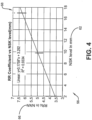
- Rolling resistance lab testing or controlled environment testing may be performed to correlate measured or calculated values of the tire wear state 62 to corresponding rolling resistance values 66 in a wear component 68 of the steady state coefficient determination module 54.
- one component of the multiple linear regression model 58 of the steady state coefficient determination module 54 is the wear component 68.
- the calculation of tire load may be performed according to any known method. Exemplary methods for the calculation of tire load 60 are shown and described in U.S. Patent Numbers 9,120,356 and 10,245,906 .
- Rolling resistance lab testing or controlled environment testing may be performed to correlate calculated values of the tire load 60 to corresponding rolling resistance values 70 in a load component 72 of the steady state coefficient determination module 54.
- the tire wear state 62 is taken into consideration in generating the load component 72 due to a correlation 74 between the tire load 60 and the tire wear state.
- another component of the multiple linear regression model 58 of the steady coefficient state determination module 54 is the load component 72.
- the inflation pressure preferably is provided by the tire sensor unit 26.
- Rolling resistance lab testing or controlled environment testing may be performed to correlate predetermined values of the tire inflation pressure 28 to corresponding rolling resistance values 76 in a pressure component 78 of the steady state coefficient determination module 54.
- the tire wear state 62 is taken into consideration in generating the pressure component 78 due to a correlation 80 between tire inflation pressure 28 and the tire wear state.
- another component of the multiple linear regression model 58 of the steady state coefficient determination module 54 is the pressure component 78.
- the wheel speed preferably is provided by a tire-mounted, wheel-mounted, or vehicle mounted speed or acceleration sensor unit.
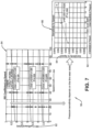
- Rolling resistance lab testing or controlled environment testing may be performed to correlate predetermined values of the wheel speed 64 to corresponding rolling resistance values 82 in a wheel speed component 84 of the steady state coefficient determination module 54.
- the tire wear state 62 is taken into consideration in generating the wheel speed component 84 due to a correlation 86 between wheel speed 64 and the tire wear state.
- another component of the multiple linear regression model 58 of the steady state coefficient determination module 54 is the wheel speed component 84.
- the steady state coefficient determination module 54 thus determines the relationship between the independent variables of the tire load 60, the tire inflation pressure 28, the tire wear state 62, and the wheel speed 64, and the dependent variable of the steady state rolling resistance coefficient 52.
- the relationship is determined by the multiple linear regression model 58, which employs the wear component 68, the load component 72, the pressure component 78, and the wheel speed component 84 to determine the steady state rolling resistance coefficient 52.
- the tire rolling resistance estimation system 10 also includes a steady state tire temperature module 90 and a real-time rolling resistance coefficient module 92.
- the steady state tire temperature module 90 employs a combination of data-driven and physics-based approaches to build a semi-empirical model for prediction of a steady state tire temperature 94, as opposed to prior art techniques, which solely employed a physics-based approach.
- the steady state tire temperature module 90 estimates the steady state tire temperature 94 based on the expected the steady state rolling resistance coefficient 52 from the steady state coefficient determination module 54, the tire load 60, and the wheel speed 64.
- the steady state tire temperature module 90 also accounts for an ambient temperature 96, which may be input from a wheel-mounted sensor, a vehicle-mounted temperature sensor, and/or a weather-based service.
- the steady state tire temperature module 90 further accounts for a ratio of an initial measured tire temperature 30i from the tire sensor unit 26 to an initial measured tire inflation pressure 28i from the tire sensor unit, and a current measured tire inflation pressure 28 from the tire sensor unit. With these inputs, the steady state tire temperature module 90 determines the steady state tire temperature 94.
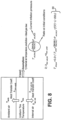
- the real-time rolling resistance coefficient module 92 preferably employs a linear model to estimate the real-time rolling resistance coefficient 50.
- the estimation of the real-time rolling resistance coefficient 50 is based on the expected the steady state rolling resistance coefficient 52 and a difference 98 between the steady state tire temperature 94 and the current tire temperature 30 from the tire sensor unit 26.
- the difference 98 between the steady state tire temperature 94 and the current tire temperature 30 indicates how far the tire 12 is from a steady state.
- a coefficient ⁇ is employed, which is a function of the tire wear state.
- the real-time rolling resistance coefficient module 92 thus generates the real-time rolling resistance coefficient 50, which accurately reflects current temperature 30 of the tire 12.
- the rolling resistance coefficient 50 may be wirelessly transmitted by an antenna 34 from the processor 40 to a display or controller device 36 and/or to the electronic control system 42 of the vehicle 14.
- the rolling resistance coefficient 50 from the tire rolling resistance estimation system 10 may thus be employed by systems that are in electronic communication with the electronic control system 42 of the vehicle 14 to predict the driving range of the vehicle, predict energy loss, and/or provide force allocation determinations.
- the tire rolling resistance estimation system 10 provides an accurate estimate of the real-time rolling resistance coefficient 50 of the tire 12 under transient driving or operating conditions.
- the system 10 includes the tire wear state 62 in the determination of the steady state rolling resistance coefficient 52, in the determination of the steady state tire temperature 94, and in the determination of the real-time rolling resistance coefficient 50.
- the system 10 also includes the tire inflation pressure 28 as an influencing variable in the determination of the steady state tire temperature 94.
- the system 10 is data-driven, leveraging the measured tire pressure 28 and temperature 30 from the tire sensor unit 26.
- the present invention also includes a method for estimating the rolling resistance of a tire.
- the method includes steps in accordance with the description that is presented above and shown in Figures 1 through 9 .
- tire rolling resistance estimation system may be altered or rearranged, or components or steps known to those skilled in the art omitted or added, without affecting the overall concept or operation of the invention.
- electronic communication may be through a wired connection or wireless communication without affecting the overall concept or operation of the invention.
- wireless communications include radio frequency (RF) and Bluetooth ® communications.
Landscapes
- Engineering & Computer Science (AREA)
- Mechanical Engineering (AREA)
- Physics & Mathematics (AREA)
- General Physics & Mathematics (AREA)
- Tires In General (AREA)
Abstract
Description
- The invention relates generally to tire monitoring. More particularly, the invention relates to systems that monitor and estimate certain characteristics of a tire. Specifically, the invention is directed to a system that estimates the rolling resistance coefficient of a tire under transient driving or operating conditions.
- Multiple tires support a vehicle, and transmit driving and braking forces from the vehicle to the road surface. It is often beneficial to estimate characteristics of a tire.
- One characteristic that is beneficial to estimate is the rolling resistance of a tire. The rolling resistance of a tire is the amount of energy that is needed to enable the tire to roll over a surface. Estimation or prediction of tire rolling resistance is important, as it enables prediction of the driving range of a vehicle. Estimation of tire rolling resistance also enables prediction of energy loss, including fuel consumption for internal combustion engines and battery consumption for electric vehicles. In addition, estimates of tire rolling resistance are employed in force allocation determinations, which may be useful in braking and other control systems of the vehicle.
- It is desirable to estimate the rolling resistance of a tire with the highest possible accuracy, but rolling resistance can be difficult to accurately predict, particularly in view of dynamic driving conditions. More particularly, the rolling resistance of a tire is a transient value or characteristic. As a tire is driven, its temperature generally increases, and rolling resistance changes as the tire temperature increases.
- In the prior art, estimates of tire rolling resistance have been determined through rolling resistance lab testing or other controlled environments. However, it is difficult to extrapolate results from rolling resistance lab tests to accurately predict rolling resistance during dynamic driving conditions. For example, the ambient temperature in lab testing is often set at a fixed value, such as about 25 degrees Celsius. Prior art estimation techniques do not include an appropriate thermal model that accounts for tire temperature prediction during driving and tire warm-up.
- As a result, there is a need in the art for a system that provides an accurate estimation of the rolling resistance of a tire under transient driving or operating conditions.
- The invention relates to a system in accordance with
claim 1 and to a method in accordance withclaim 14. - Dependent claims refer to preferred embodiments of the invention.
- According to an aspect of an exemplary embodiment of the invention, a tire rolling resistance estimation system is provided. The system estimates a real-time rolling resistance coefficient of a tire supporting a vehicle, and includes a tire sensor unit mounted to the tire, in which the tire sensor unit measures an inflation pressure of the tire and a temperature of the tire. A processor is in electronic communication with the tire sensor unit. A steady state coefficient determination module is in electronic communication with the processor, receives a plurality of inputs, and determines a steady state rolling resistance coefficient of the tire. A steady state tire temperature module is in electronic communication with the processor, receives the steady state rolling resistance coefficient of the tire from the steady state coefficient determination module, and estimates a steady state tire temperature of the tire. A real-time rolling resistance coefficient module is in electronic communication with the processor and receives the steady state tire temperature of the tire from the steady state tire temperature module. The real-time rolling resistance coefficient module estimates a real-time rolling resistance coefficient of the tire from the steady state rolling resistance coefficient and a difference between the steady state tire temperature and a current tire temperature from the tire sensor unit.
- The invention will be described by way of example and with reference to the accompanying drawings, in which:
-
Figure 1 is a schematic perspective view of a vehicle that includes a tire which employs an exemplary embodiment of a tire rolling resistance estimation system of the present invention; -
Figure 2 is a schematic representation of data transmission to a cloud-based server and to a device; -
Figure 3 is a schematic diagram of an exemplary embodiment of the tire rolling resistance estimation system of the present invention; -
Figure 4 is a graphical representation of an aspect of the exemplary embodiment of the tire rolling resistance estimation system shown inFigure 3 ; -
Figure 5 is a graphical representation of another aspect of the exemplary embodiment of the tire rolling resistance estimation system shown inFigure 3 ; -
Figure 6 is a graphical representation of another aspect of the exemplary embodiment of the tire rolling resistance estimation system shown inFigure 3 ; -
Figure 7 is a graphical representation of another aspect of the exemplary embodiment of the tire rolling resistance estimation system shown inFigure 3 ; -
Figure 8 is a graphical representation of another aspect of the exemplary embodiment of the tire rolling resistance estimation system shown inFigure 3 ; and -
Figure 9 is a graphical representation of another aspect of the exemplary embodiment of the tire rolling resistance estimation system shown inFigure 3 . - Similar numerals refer to similar parts throughout the drawings.
- "ANN" or "artificial neural network" is an adaptive tool for non-linear statistical data modeling that changes its structure based on external or internal information that flows through a network during a learning phase. ANN neural networks are non-linear statistical data modeling tools used to model complex relationships between inputs and outputs or to find patterns in data.
- "Axial" and "axially" means lines or directions that are parallel to the axis of rotation of the tire.
- "CAN bus" or "CAN bus system" is an abbreviation for controller area network system, which is a vehicle bus standard designed to allow microcontrollers and devices to communicate with each other within a vehicle without a host computer.
- "Circumferential" means lines or directions extending along the perimeter of the surface of the annular tread perpendicular to the axial direction.
- "Equatorial centerplane" means the plane perpendicular to the tire's axis of rotation and passing through the center of the tread.
- "Footprint" means the contact patch or area of contact created by the tire tread with a flat surface as the tire rotates or rolls.
- "Inboard side" means the side of the tire nearest the vehicle when the tire is mounted on a wheel and the wheel is mounted on the vehicle.
- "Lateral" means an axial direction.
- "Lateral edges" means a line tangent to the axially outermost tread contact patch or footprint of the tire as measured under normal load and tire inflation, the lines being parallel to the equatorial centerplane.
- "Net contact area" means the total area of ground contacting tread elements between the lateral edges around the entire circumference of the tread of the tire divided by the gross area of the entire tread between the lateral edges.
- "Outboard side" means the side of the tire farthest away from the vehicle when the tire is mounted on a wheel and the wheel is mounted on the vehicle.
- "Radial" and "radially" means directions radially toward or away from the axis of rotation of the tire.
- "Rib" means a circumferentially extending strip of rubber on the tread which is defined by at least one circumferential groove and either a second such groove or a lateral edge, the strip being laterally undivided by full-depth grooves.
- "Tread element" or "traction element" means a rib or a block element defined by a shape having adjacent grooves.
- With reference to
Figures 1 through 9 , an exemplary embodiment of the tire rollingresistance estimation system 10 of the present invention is shown. - With particular reference to
Figure 1 , thesystem 10 estimates the rolling resistance of eachtire 12 supporting avehicle 14. It is to be understood that thevehicle 14 may be any vehicle type, and is shown by way of example as a passenger car. Thetires 12 are of conventional construction, and each tire is mounted on arespective wheel 16 as known to those skilled in the art. Eachtire 12 includes a pair ofsidewalls 18 that extend to acircumferential tread 20, which wears with age from road abrasion. Aninnerliner 22 is disposed on the inner surface of thetire 12, and when the tire is mounted on thewheel 16, aninternal cavity 24 is formed, which is filled with a pressurized fluid, such as air. - A
tire sensor unit 26 is mounted to eachtire 12, such as by attachment to theinnerliner 22 by means such as an adhesive, and measures certain characteristics of the tire, such as tire inflation pressure 28 (Figure 3 ) andtire temperature 30. For this reason, thetire sensor unit 26 preferably includes a pressure sensor and a temperature sensor, and may be of any known configuration, such as a tire pressure management system (TPMS) sensor. Thetire sensor unit 26 may also include electronic memory capacity for storing identification (ID) information for eachtire 12, known as tire ID information. It is to be understood that thetire sensor unit 26 may be mounted on a component or structure of thetire 12 other than theinnerliner 22. - Turning to
Figure 2 , aspects of the tire rollingresistance estimation system 10 preferably are executed on aprocessor 40. Theprocessor 40 enables input of parameters and execution of specific techniques, to be described below, which are stored in a suitable storage medium and are in electronic communication with the processor. Theprocessor 40 may be mounted on thevehicle 14, may be in communication with anelectronic control system 42 of the vehicle, such as the vehicle CAN bus system, and/or may be a remote processor in a cloud-basedserver 44. - Wireless transmission means 32, such as an antenna, may wirelessly send the measured
tire pressure 28 andtire temperature 30 from the tire sensor unit 26 (Figure 1 ) to theprocessor 40. Output from the tire rollingresistance estimation system 10 may be wirelessly transmitted by anantenna 34 from theprocessor 40 to a display orcontroller device 36 and/or to theelectronic control system 42 of thevehicle 14. - Referring to
Figure 3 , the tire rollingresistance estimation system 10 provides an estimation of the rolling resistance of thetire 12. Rolling resistance is often expressed as a coefficient multiplied by normal force, and the coefficient is referred to as the rolling resistance coefficient (RRc), indicated at 50. The goal of thesystem 10 is to predict or estimate an accurate real-time rollingresistance coefficient 50 under transient driving or operating conditions of thetire 12. - In the tire rolling
resistance estimation system 10, a steady state rollingresistance coefficient 52 is determined with a steady statecoefficient determination module 54. The steady statecoefficient determination module 54 preferably employs aregression model 58 withmultiple inputs 56. Apreferred regression model 58 is a multiple linear regression model, which determines the relationship between multiple independent variables, which are theinputs 56, and one dependent variable, which is the steady state rollingresistance coefficient 52. By way of example, theinputs 56 may include atire load 60, thetire inflation pressure 28, awear state 62 of thetire 12, and a rotational or rolling speed of the tire, which is referred to as awheel speed 64. - With additional reference to
Figure 4 , turning to theinput 56 of thetire wear state 62, the tire wear state may be directly measured as an amount of remaining non-skid depth of thetread 20, or may be calculated according to any known method. An exemplary method for the calculation oftire wear state 62 is shown and described inU.S. Published Patent Application Number 2019/0001757 . - Rolling resistance lab testing or controlled environment testing may be performed to correlate measured or calculated values of the
tire wear state 62 to corresponding rolling resistance values 66 in awear component 68 of the steady statecoefficient determination module 54. In this manner, one component of the multiplelinear regression model 58 of the steady statecoefficient determination module 54 is thewear component 68. - Turning to
Figure 5 , for theinput 56 of thetire load 60, the calculation of tire load may be performed according to any known method. Exemplary methods for the calculation oftire load 60 are shown and described inU.S. Patent Numbers 9,120,356 10,245,906 - Rolling resistance lab testing or controlled environment testing may be performed to correlate calculated values of the
tire load 60 to corresponding rolling resistance values 70 in aload component 72 of the steady statecoefficient determination module 54. Preferably, thetire wear state 62 is taken into consideration in generating theload component 72 due to a correlation 74 between thetire load 60 and the tire wear state. In this manner, another component of the multiplelinear regression model 58 of the steady coefficientstate determination module 54 is theload component 72. - Referring to
Figure 6 , for theinput 56 of thetire inflation pressure 28, the inflation pressure preferably is provided by thetire sensor unit 26. Rolling resistance lab testing or controlled environment testing may be performed to correlate predetermined values of thetire inflation pressure 28 to corresponding rolling resistance values 76 in apressure component 78 of the steady statecoefficient determination module 54. Preferably, thetire wear state 62 is taken into consideration in generating thepressure component 78 due to acorrelation 80 betweentire inflation pressure 28 and the tire wear state. In this manner, another component of the multiplelinear regression model 58 of the steady statecoefficient determination module 54 is thepressure component 78. - Referring to
Figure 7 , for theinput 56 of thewheel speed 64, the wheel speed preferably is provided by a tire-mounted, wheel-mounted, or vehicle mounted speed or acceleration sensor unit. Rolling resistance lab testing or controlled environment testing may be performed to correlate predetermined values of thewheel speed 64 to corresponding rolling resistance values 82 in awheel speed component 84 of the steady statecoefficient determination module 54. Preferably, thetire wear state 62 is taken into consideration in generating thewheel speed component 84 due to acorrelation 86 betweenwheel speed 64 and the tire wear state. In this manner, another component of the multiplelinear regression model 58 of the steady statecoefficient determination module 54 is thewheel speed component 84. - Returning to
Figure 3 , the steady statecoefficient determination module 54 thus determines the relationship between the independent variables of thetire load 60, thetire inflation pressure 28, thetire wear state 62, and thewheel speed 64, and the dependent variable of the steady state rollingresistance coefficient 52. The relationship is determined by the multiplelinear regression model 58, which employs thewear component 68, theload component 72, thepressure component 78, and thewheel speed component 84 to determine the steady state rollingresistance coefficient 52. - The tire rolling
resistance estimation system 10 also includes a steady statetire temperature module 90 and a real-time rollingresistance coefficient module 92. With additional reference toFigure 8 , the steady statetire temperature module 90 employs a combination of data-driven and physics-based approaches to build a semi-empirical model for prediction of a steadystate tire temperature 94, as opposed to prior art techniques, which solely employed a physics-based approach. - The steady state
tire temperature module 90 estimates the steadystate tire temperature 94 based on the expected the steady state rollingresistance coefficient 52 from the steady statecoefficient determination module 54, thetire load 60, and thewheel speed 64. The steady statetire temperature module 90 also accounts for anambient temperature 96, which may be input from a wheel-mounted sensor, a vehicle-mounted temperature sensor, and/or a weather-based service. The steady statetire temperature module 90 further accounts for a ratio of an initial measured tire temperature 30i from thetire sensor unit 26 to an initial measuredtire inflation pressure 28i from the tire sensor unit, and a current measuredtire inflation pressure 28 from the tire sensor unit. With these inputs, the steady statetire temperature module 90 determines the steadystate tire temperature 94. - Referring to
Figures 3 and9 , the real-time rollingresistance coefficient module 92 preferably employs a linear model to estimate the real-time rollingresistance coefficient 50. The estimation of the real-time rollingresistance coefficient 50 is based on the expected the steady state rollingresistance coefficient 52 and adifference 98 between the steadystate tire temperature 94 and thecurrent tire temperature 30 from thetire sensor unit 26. Thedifference 98 between the steadystate tire temperature 94 and thecurrent tire temperature 30 indicates how far thetire 12 is from a steady state. To account for thetire wear state 62 in the real-time rollingresistance coefficient module 92, a coefficient α is employed, which is a function of the tire wear state. - The real-time rolling
resistance coefficient module 92 thus generates the real-time rollingresistance coefficient 50, which accurately reflectscurrent temperature 30 of thetire 12. As shown inFigure 2 , the rollingresistance coefficient 50 may be wirelessly transmitted by anantenna 34 from theprocessor 40 to a display orcontroller device 36 and/or to theelectronic control system 42 of thevehicle 14. The rollingresistance coefficient 50 from the tire rollingresistance estimation system 10 may thus be employed by systems that are in electronic communication with theelectronic control system 42 of thevehicle 14 to predict the driving range of the vehicle, predict energy loss, and/or provide force allocation determinations. - In this manner, the tire rolling
resistance estimation system 10 provides an accurate estimate of the real-time rollingresistance coefficient 50 of thetire 12 under transient driving or operating conditions. Thesystem 10 includes thetire wear state 62 in the determination of the steady state rollingresistance coefficient 52, in the determination of the steadystate tire temperature 94, and in the determination of the real-time rollingresistance coefficient 50. Thesystem 10 also includes thetire inflation pressure 28 as an influencing variable in the determination of the steadystate tire temperature 94. Thesystem 10 is data-driven, leveraging the measuredtire pressure 28 andtemperature 30 from thetire sensor unit 26. - The present invention also includes a method for estimating the rolling resistance of a tire. The method includes steps in accordance with the description that is presented above and shown in
Figures 1 through 9 . - It is to be understood that the structure and method of the above-described tire rolling resistance estimation system may be altered or rearranged, or components or steps known to those skilled in the art omitted or added, without affecting the overall concept or operation of the invention. For example, electronic communication may be through a wired connection or wireless communication without affecting the overall concept or operation of the invention. Such wireless communications include radio frequency (RF) and Bluetooth® communications.
Claims (15)
- A tire rolling resistance estimation system, the system (10) estimating a real-time rolling resistance coefficient (50) of a tire (12) supporting a vehicle (14), the system (10) including:a tire sensor unit (26) mounted to the tire (12), the tire sensor unit (26) being configured for measuring an inflation pressure of the tire and a temperature of the tire;a processor (40) in electronic communication with the tire sensor unit (26);a steady state coefficient determination module (54) in electronic communication with the processor (40), the steady state coefficient determination module (54) being configured for receiving a plurality of inputs and for determining a steady state rolling resistance coefficient of the tire;a steady state tire temperature module (90) in electronic communication with the processor (40), the steady state tire temperature module (90) being configured for receiving the steady state rolling resistance coefficient of the tire from the steady state coefficient determination module (54) and for estimating a steady state tire temperature of the tire; anda real-time rolling resistance coefficient module (92) in electronic communication with the processor (40), the real-time rolling resistance coefficient (92) module being configured for receiving the steady state tire temperature of the tire from the steady state tire temperature module and for estimating a real-time rolling resistance coefficient of the tire from the steady state rolling resistance coefficient and a difference between the steady state tire temperature and a current tire temperature from the tire sensor unit (26).
- The system of claim 1, wherein the real-time rolling resistance coefficient is the coefficient under transient operating conditions of the tire (12).
- The system of claim 1 or 2, wherein the steady state coefficient determination module (54) is configured for employing a regression model (58).
- The system of at least one of the previous claims, wherein the regression model (58) includes a multiple linear regression model.
- The system of at least one of the previous claims, wherein the plurality of inputs include at least one of a tire load, an inflation pressure of the tire, a wear state of the tire, and a wheel speed of the tire.
- The system of at least one of the previous claims, wherein the steady state coefficient determination module (54) includes a wear component, the wear component being configured for correlating values of the wear state of the tire to corresponding rolling resistance values; and/or wherein the steady state coefficient determination module (54) includes a load component, the load component being configured for correlating values of the tire load to corresponding rolling resistance values and, optionally, the load component being configured for accounting for the wear state of the tire.
- The system of at least one of the previous claims, wherein the steady state coefficient determination module (54) includes a pressure component, the pressure component being configured for correlating values of the tire inflation pressure to corresponding rolling resistance values and, optionally, the pressure component being configured for accounting for the wear state of the tire.
- The system of at least one of the previous claims, wherein the steady state coefficient determination module (54) includes a wheel speed component, the wheel speed component being configured for correlating values of the wheel speed to corresponding rolling resistance values and, optionally, the wheel speed component being configured for accounting for the wear state of the tire.
- The system of at least one of the previous claims, wherein the steady state tire temperature module (90) is configured for estimating the steady state tire temperature based on the steady state rolling resistance coefficient of the tire, a tire load, and a wheel speed of the tire and, optionally, the steady state tire temperature module being configured for accounting for an ambient temperature.
- The system of at least one of the previous claims, wherein the steady state tire temperature module (90) is configured for accounting for a ratio of an initial measured tire temperature from the tire sensor unit (26) to an initial measured tire inflation pressure from the tire sensor unit.
- The system of at least one of the previous claims, wherein the steady state tire temperature module (90) is configured for accounting for a current measured tire inflation pressure from the tire sensor unit.
- The system of at least one of the previous claims, wherein the real-time rolling resistance coefficient module (92) includes a linear model (58).
- The system of at least one of the previous claims, wherein the real-time rolling resistance coefficient module (92) is configured for employing a function of the tire wear state.
- A tire rolling resistance estimation method, the method estimating a real-time rolling resistance coefficient of a tire (12) supporting a vehicle (14), the method including:providing a tire sensor unit (26) mounted to the tire, the tire sensor unit measuring an inflation pressure of the tire and a temperature of the tire;providing a processor (40) in electronic communication with the tire sensor unit (26);providing a steady state coefficient determination module (54) in electronic communication with the processor, the steady state coefficient determination module receiving a plurality of inputs and determining a steady state rolling resistance coefficient of the tire;providing a steady state tire temperature module (90) in electronic communication with the processor, the steady state tire temperature module receiving the steady state rolling resistance coefficient of the tire from the steady state coefficient determination module and estimating a steady state tire temperature of the tire; andproviding a real-time rolling resistance coefficient module (92) in electronic communication with the processor, the real-time rolling resistance coefficient module receiving the steady state tire temperature of the tire from the steady state tire temperature module and estimating a real-time rolling resistance coefficient of the tire from the steady state rolling resistance coefficient and a difference between the steady state tire temperature and a current tire temperature from the tire sensor unit (26).
- The method of claim 14 wherein the method is implemented using a system (10) in accordance with at least one of the claims 1 to 13.
Applications Claiming Priority (2)
| Application Number | Priority Date | Filing Date | Title |
|---|---|---|---|
| US202263385412P | 2022-11-30 | 2022-11-30 | |
| US18/506,589 US20240174034A1 (en) | 2022-11-30 | 2023-11-10 | Tire rolling resistance estimation system |
Publications (2)
| Publication Number | Publication Date |
|---|---|
| EP4379346A1 true EP4379346A1 (en) | 2024-06-05 |
| EP4379346B1 EP4379346B1 (en) | 2025-10-01 |
Family
ID=88969755
Family Applications (1)
| Application Number | Title | Priority Date | Filing Date |
|---|---|---|---|
| EP23212111.1A Active EP4379346B1 (en) | 2022-11-30 | 2023-11-24 | Tire rolling resistance estimation system and method |
Country Status (2)
| Country | Link |
|---|---|
| US (1) | US20240174034A1 (en) |
| EP (1) | EP4379346B1 (en) |
Families Citing this family (1)
| Publication number | Priority date | Publication date | Assignee | Title |
|---|---|---|---|---|
| US20260141756A1 (en) * | 2024-11-21 | 2026-05-21 | The Goodyear Tire & Rubber Company | Transient tire energy dissipation analysis |
Citations (4)
| Publication number | Priority date | Publication date | Assignee | Title |
|---|---|---|---|---|
| US9120356B2 (en) | 2012-06-27 | 2015-09-01 | The Goodyear Tire & Rubber Company | Load estimation system and method for a vehicle tire |
| US20190001757A1 (en) | 2017-06-29 | 2019-01-03 | The Goodyear Tire & Rubber Company | Tire wear state estimation system and method |
| US10245906B2 (en) | 2014-11-11 | 2019-04-02 | The Goodyear Tire & Rubber Company | Tire wear compensated load estimation system and method |
| US20220299405A1 (en) * | 2021-03-19 | 2022-09-22 | Sensata Technologies, Inc. | Enhanced method and system to estimate the tire operating efficiency and range of an electric vehicle |
Family Cites Families (2)
| Publication number | Priority date | Publication date | Assignee | Title |
|---|---|---|---|---|
| US11592358B2 (en) * | 2019-11-14 | 2023-02-28 | University Of South Carolina | Sensing in tires for rolling resistance |
| CN117715771A (en) * | 2021-08-27 | 2024-03-15 | 普利司通美国轮胎运营有限责任公司 | System and method for estimating in real time the rolling resistance of a tyre |
-
2023
- 2023-11-10 US US18/506,589 patent/US20240174034A1/en active Pending
- 2023-11-24 EP EP23212111.1A patent/EP4379346B1/en active Active
Patent Citations (4)
| Publication number | Priority date | Publication date | Assignee | Title |
|---|---|---|---|---|
| US9120356B2 (en) | 2012-06-27 | 2015-09-01 | The Goodyear Tire & Rubber Company | Load estimation system and method for a vehicle tire |
| US10245906B2 (en) | 2014-11-11 | 2019-04-02 | The Goodyear Tire & Rubber Company | Tire wear compensated load estimation system and method |
| US20190001757A1 (en) | 2017-06-29 | 2019-01-03 | The Goodyear Tire & Rubber Company | Tire wear state estimation system and method |
| US20220299405A1 (en) * | 2021-03-19 | 2022-09-22 | Sensata Technologies, Inc. | Enhanced method and system to estimate the tire operating efficiency and range of an electric vehicle |
Non-Patent Citations (2)
| Title |
|---|
| EJSMONT JERZY ET AL: "Influence of temperature on the tyre rolling resistance", INTERNATIONAL JOURNAL OF AUTOMOTIVE TECHNOLOGY, THE KOREAN SOCIETY OF AUTOMOTIVE ENGINEERS, HEIDELBERG, vol. 19, no. 1, 3 October 2017 (2017-10-03), pages 45 - 54, XP036332008, ISSN: 1229-9138, [retrieved on 20171003], DOI: 10.1007/S12239-018-0005-4 * |
| MARS ET AL: "An Analytical Model for the Transient Rolling Resistance Behavior of Tires", vol. 27, no. 3, 1 July 1999 (1999-07-01), pages 161 - 175, XP009544922, ISSN: 0090-8657, Retrieved from the Internet <URL:http://meridian.allenpress.com/tst/article-pdf/27/3/161/1974629/1_2135982.pdf> DOI: 10.2346/1.2135982 * |
Also Published As
| Publication number | Publication date |
|---|---|
| EP4379346B1 (en) | 2025-10-01 |
| US20240174034A1 (en) | 2024-05-30 |
Similar Documents
| Publication | Publication Date | Title |
|---|---|---|
| CN112440628B (en) | Tire wear estimation system and method using footprint length | |
| EP3421267B1 (en) | Tire wear state estimation system and method | |
| EP3858690B1 (en) | Method for estimating tire grip | |
| EP3957501B1 (en) | Tire high temperature forecasting system and method | |
| EP3785942B1 (en) | Method for extracting changes in tire characteristics | |
| EP4197822B1 (en) | Tire replacement system and method | |
| CN115519942B (en) | Tire Replacement Prediction System and Method | |
| EP4379346B1 (en) | Tire rolling resistance estimation system and method | |
| EP4385762B1 (en) | System and method for estimation of tire tread depth employing wheel speed | |
| EP4368419A1 (en) | System and method for auto-location of tires employing footprint length | |
| EP4385767B1 (en) | System and method for auto-location of tires employing footprint length | |
| US12589618B2 (en) | Method and system for monitoring tire inflation pressure | |
| EP4140838B1 (en) | Road condition monitoring system and method | |
| CN118107594A (en) | Tire rolling resistance estimation system | |
| EP4385763B1 (en) | System and method for estimation of remaining tire mileage | |
| EP4151436B1 (en) | Counter-deflection load estimation system and method | |
| CN118182019A (en) | Tire remaining mileage estimation system | |
| CN118182021A (en) | System for automatically positioning tire by utilizing print length | |
| CN116278523A (en) | tire changing system | |
| CN118024792A (en) | Method and system for monitoring tire inflation pressure |
Legal Events
| Date | Code | Title | Description |
|---|---|---|---|
| PUAI | Public reference made under article 153(3) epc to a published international application that has entered the european phase |
Free format text: ORIGINAL CODE: 0009012 |
|
| STAA | Information on the status of an ep patent application or granted ep patent |
Free format text: STATUS: THE APPLICATION HAS BEEN PUBLISHED |
|
| AK | Designated contracting states |
Kind code of ref document: A1 Designated state(s): AL AT BE BG CH CY CZ DE DK EE ES FI FR GB GR HR HU IE IS IT LI LT LU LV MC ME MK MT NL NO PL PT RO RS SE SI SK SM TR |
|
| STAA | Information on the status of an ep patent application or granted ep patent |
Free format text: STATUS: REQUEST FOR EXAMINATION WAS MADE |
|
| 17P | Request for examination filed |
Effective date: 20241205 |
|
| GRAP | Despatch of communication of intention to grant a patent |
Free format text: ORIGINAL CODE: EPIDOSNIGR1 |
|
| STAA | Information on the status of an ep patent application or granted ep patent |
Free format text: STATUS: GRANT OF PATENT IS INTENDED |
|
| INTG | Intention to grant announced |
Effective date: 20250513 |
|
| GRAS | Grant fee paid |
Free format text: ORIGINAL CODE: EPIDOSNIGR3 |
|
| GRAA | (expected) grant |
Free format text: ORIGINAL CODE: 0009210 |
|
| STAA | Information on the status of an ep patent application or granted ep patent |
Free format text: STATUS: THE PATENT HAS BEEN GRANTED |
|
| AK | Designated contracting states |
Kind code of ref document: B1 Designated state(s): AL AT BE BG CH CY CZ DE DK EE ES FI FR GB GR HR HU IE IS IT LI LT LU LV MC ME MK MT NL NO PL PT RO RS SE SI SK SM TR |
|
| REG | Reference to a national code |
Ref country code: GB Ref legal event code: FG4D Ref country code: CH Ref legal event code: F10 Free format text: ST27 STATUS EVENT CODE: U-0-0-F10-F00 (AS PROVIDED BY THE NATIONAL OFFICE) Effective date: 20251001 |
|
| REG | Reference to a national code |
Ref country code: IE Ref legal event code: FG4D |
|
| REG | Reference to a national code |
Ref country code: DE Ref legal event code: R096 Ref document number: 602023007136 Country of ref document: DE |
|
| PGFP | Annual fee paid to national office [announced via postgrant information from national office to epo] |
Ref country code: DE Payment date: 20251022 Year of fee payment: 3 |
|
| PGFP | Annual fee paid to national office [announced via postgrant information from national office to epo] |
Ref country code: AT Payment date: 20260113 Year of fee payment: 3 |
|
| PGFP | Annual fee paid to national office [announced via postgrant information from national office to epo] |
Ref country code: FR Payment date: 20251119 Year of fee payment: 3 |
|
| REG | Reference to a national code |
Ref country code: NL Ref legal event code: MP Effective date: 20251001 |
|
| REG | Reference to a national code |
Ref country code: AT Ref legal event code: MK05 Ref document number: 1842914 Country of ref document: AT Kind code of ref document: T Effective date: 20251001 |
|
| PG25 | Lapsed in a contracting state [announced via postgrant information from national office to epo] |
Ref country code: NL Free format text: LAPSE BECAUSE OF FAILURE TO SUBMIT A TRANSLATION OF THE DESCRIPTION OR TO PAY THE FEE WITHIN THE PRESCRIBED TIME-LIMIT Effective date: 20251001 |
|
| PG25 | Lapsed in a contracting state [announced via postgrant information from national office to epo] |
Ref country code: ES Free format text: LAPSE BECAUSE OF FAILURE TO SUBMIT A TRANSLATION OF THE DESCRIPTION OR TO PAY THE FEE WITHIN THE PRESCRIBED TIME-LIMIT Effective date: 20251001 |
|
| REG | Reference to a national code |
Ref country code: LT Ref legal event code: MG9D |
|
| PG25 | Lapsed in a contracting state [announced via postgrant information from national office to epo] |
Ref country code: NO Free format text: LAPSE BECAUSE OF FAILURE TO SUBMIT A TRANSLATION OF THE DESCRIPTION OR TO PAY THE FEE WITHIN THE PRESCRIBED TIME-LIMIT Effective date: 20260101 |
|
| PG25 | Lapsed in a contracting state [announced via postgrant information from national office to epo] |
Ref country code: FI Free format text: LAPSE BECAUSE OF FAILURE TO SUBMIT A TRANSLATION OF THE DESCRIPTION OR TO PAY THE FEE WITHIN THE PRESCRIBED TIME-LIMIT Effective date: 20251001 Ref country code: AT Free format text: LAPSE BECAUSE OF FAILURE TO SUBMIT A TRANSLATION OF THE DESCRIPTION OR TO PAY THE FEE WITHIN THE PRESCRIBED TIME-LIMIT Effective date: 20251001 Ref country code: HR Free format text: LAPSE BECAUSE OF FAILURE TO SUBMIT A TRANSLATION OF THE DESCRIPTION OR TO PAY THE FEE WITHIN THE PRESCRIBED TIME-LIMIT Effective date: 20251001 |
|
| PG25 | Lapsed in a contracting state [announced via postgrant information from national office to epo] |
Ref country code: RS Free format text: LAPSE BECAUSE OF FAILURE TO SUBMIT A TRANSLATION OF THE DESCRIPTION OR TO PAY THE FEE WITHIN THE PRESCRIBED TIME-LIMIT Effective date: 20260101 |
|
| PG25 | Lapsed in a contracting state [announced via postgrant information from national office to epo] |
Ref country code: IS Free format text: LAPSE BECAUSE OF FAILURE TO SUBMIT A TRANSLATION OF THE DESCRIPTION OR TO PAY THE FEE WITHIN THE PRESCRIBED TIME-LIMIT Effective date: 20260201 |
|
| PG25 | Lapsed in a contracting state [announced via postgrant information from national office to epo] |
Ref country code: PT Free format text: LAPSE BECAUSE OF FAILURE TO SUBMIT A TRANSLATION OF THE DESCRIPTION OR TO PAY THE FEE WITHIN THE PRESCRIBED TIME-LIMIT Effective date: 20260202 Ref country code: CZ Free format text: LAPSE BECAUSE OF FAILURE TO SUBMIT A TRANSLATION OF THE DESCRIPTION OR TO PAY THE FEE WITHIN THE PRESCRIBED TIME-LIMIT Effective date: 20251001 |
|
| PG25 | Lapsed in a contracting state [announced via postgrant information from national office to epo] |
Ref country code: PL Free format text: LAPSE BECAUSE OF FAILURE TO SUBMIT A TRANSLATION OF THE DESCRIPTION OR TO PAY THE FEE WITHIN THE PRESCRIBED TIME-LIMIT Effective date: 20251001 |
|
| PG25 | Lapsed in a contracting state [announced via postgrant information from national office to epo] |
Ref country code: LV Free format text: LAPSE BECAUSE OF FAILURE TO SUBMIT A TRANSLATION OF THE DESCRIPTION OR TO PAY THE FEE WITHIN THE PRESCRIBED TIME-LIMIT Effective date: 20251001 |
|
| PG25 | Lapsed in a contracting state [announced via postgrant information from national office to epo] |
Ref country code: BG Free format text: LAPSE BECAUSE OF FAILURE TO SUBMIT A TRANSLATION OF THE DESCRIPTION OR TO PAY THE FEE WITHIN THE PRESCRIBED TIME-LIMIT Effective date: 20251001 |
|
| PG25 | Lapsed in a contracting state [announced via postgrant information from national office to epo] |
Ref country code: RO Free format text: LAPSE BECAUSE OF FAILURE TO SUBMIT A TRANSLATION OF THE DESCRIPTION OR TO PAY THE FEE WITHIN THE PRESCRIBED TIME-LIMIT Effective date: 20251001 |
|
| PG25 | Lapsed in a contracting state [announced via postgrant information from national office to epo] |
Ref country code: LT Free format text: LAPSE BECAUSE OF FAILURE TO SUBMIT A TRANSLATION OF THE DESCRIPTION OR TO PAY THE FEE WITHIN THE PRESCRIBED TIME-LIMIT Effective date: 20251001 |
|
| PG25 | Lapsed in a contracting state [announced via postgrant information from national office to epo] |
Ref country code: MC Free format text: LAPSE BECAUSE OF FAILURE TO SUBMIT A TRANSLATION OF THE DESCRIPTION OR TO PAY THE FEE WITHIN THE PRESCRIBED TIME-LIMIT Effective date: 20251001 |
|
| REG | Reference to a national code |
Ref country code: DE Ref legal event code: R097 Ref document number: 602023007136 Country of ref document: DE |
|
| PG25 | Lapsed in a contracting state [announced via postgrant information from national office to epo] |
Ref country code: SM Free format text: LAPSE BECAUSE OF FAILURE TO SUBMIT A TRANSLATION OF THE DESCRIPTION OR TO PAY THE FEE WITHIN THE PRESCRIBED TIME-LIMIT Effective date: 20251001 |
|
| PG25 | Lapsed in a contracting state [announced via postgrant information from national office to epo] |
Ref country code: DK Free format text: LAPSE BECAUSE OF FAILURE TO SUBMIT A TRANSLATION OF THE DESCRIPTION OR TO PAY THE FEE WITHIN THE PRESCRIBED TIME-LIMIT Effective date: 20251001 |
|
| PG25 | Lapsed in a contracting state [announced via postgrant information from national office to epo] |
Ref country code: IT Free format text: LAPSE BECAUSE OF FAILURE TO SUBMIT A TRANSLATION OF THE DESCRIPTION OR TO PAY THE FEE WITHIN THE PRESCRIBED TIME-LIMIT Effective date: 20251001 |
|
| PG25 | Lapsed in a contracting state [announced via postgrant information from national office to epo] |
Ref country code: LU Free format text: LAPSE BECAUSE OF NON-PAYMENT OF DUE FEES Effective date: 20251124 |
|
| PG25 | Lapsed in a contracting state [announced via postgrant information from national office to epo] |
Ref country code: EE Free format text: LAPSE BECAUSE OF FAILURE TO SUBMIT A TRANSLATION OF THE DESCRIPTION OR TO PAY THE FEE WITHIN THE PRESCRIBED TIME-LIMIT Effective date: 20251001 |
|
| PG25 | Lapsed in a contracting state [announced via postgrant information from national office to epo] |
Ref country code: SK Free format text: LAPSE BECAUSE OF FAILURE TO SUBMIT A TRANSLATION OF THE DESCRIPTION OR TO PAY THE FEE WITHIN THE PRESCRIBED TIME-LIMIT Effective date: 20251001 |
|
| PG25 | Lapsed in a contracting state [announced via postgrant information from national office to epo] |
Ref country code: SE Free format text: LAPSE BECAUSE OF FAILURE TO SUBMIT A TRANSLATION OF THE DESCRIPTION OR TO PAY THE FEE WITHIN THE PRESCRIBED TIME-LIMIT Effective date: 20251001 |
|
| PLBE | No opposition filed within time limit |
Free format text: ORIGINAL CODE: 0009261 |
|
| STAA | Information on the status of an ep patent application or granted ep patent |
Free format text: STATUS: NO OPPOSITION FILED WITHIN TIME LIMIT |
|
| REG | Reference to a national code |
Ref country code: CH Ref legal event code: L10 Free format text: ST27 STATUS EVENT CODE: U-0-0-L10-L00 (AS PROVIDED BY THE NATIONAL OFFICE) Effective date: 20260812 |