EP4379308A1 - Telescope range finder based on thermal image-wind speed-noise and ranging method thereof - Google Patents
Telescope range finder based on thermal image-wind speed-noise and ranging method thereof Download PDFInfo
- Publication number
- EP4379308A1 EP4379308A1 EP23204072.5A EP23204072A EP4379308A1 EP 4379308 A1 EP4379308 A1 EP 4379308A1 EP 23204072 A EP23204072 A EP 23204072A EP 4379308 A1 EP4379308 A1 EP 4379308A1
- Authority
- EP
- European Patent Office
- Prior art keywords
- range finder
- wind speed
- noise
- thermal image
- processor
- Prior art date
- Legal status (The legal status is an assumption and is not a legal conclusion. Google has not performed a legal analysis and makes no representation as to the accuracy of the status listed.)
- Granted
Links
Images

Classifications
-
- F—MECHANICAL ENGINEERING; LIGHTING; HEATING; WEAPONS; BLASTING
- F41—WEAPONS
- F41G—WEAPON SIGHTS; AIMING
- F41G3/00—Aiming or laying means
- F41G3/06—Aiming or laying means with rangefinder
-
- A—HUMAN NECESSITIES
- A63—SPORTS; GAMES; AMUSEMENTS
- A63B—APPARATUS FOR PHYSICAL TRAINING, GYMNASTICS, SWIMMING, CLIMBING, OR FENCING; BALL GAMES; TRAINING EQUIPMENT
- A63B69/00—Training appliances or apparatus for special sports
- A63B69/36—Training appliances or apparatus for special sports for golf
- A63B69/3658—Means associated with the ball for indicating or measuring, e.g. speed, direction
-
- F—MECHANICAL ENGINEERING; LIGHTING; HEATING; WEAPONS; BLASTING
- F41—WEAPONS
- F41G—WEAPON SIGHTS; AIMING
- F41G3/00—Aiming or laying means
- F41G3/08—Aiming or laying means with means for compensating for speed, direction, temperature, pressure, or humidity of the atmosphere
-
- F—MECHANICAL ENGINEERING; LIGHTING; HEATING; WEAPONS; BLASTING
- F41—WEAPONS
- F41G—WEAPON SIGHTS; AIMING
- F41G3/00—Aiming or laying means
- F41G3/14—Indirect aiming means
- F41G3/16—Sighting devices adapted for indirect laying of fire
- F41G3/165—Sighting devices adapted for indirect laying of fire using a TV-monitor
-
- G—PHYSICS
- G01—MEASURING; TESTING
- G01P—MEASURING LINEAR OR ANGULAR SPEED, ACCELERATION, DECELERATION, OR SHOCK; INDICATING PRESENCE, ABSENCE, OR DIRECTION, OF MOVEMENT
- G01P5/00—Measuring speed of fluids, e.g. of air stream; Measuring speed of bodies relative to fluids, e.g. of ship, of aircraft
- G01P5/10—Measuring speed of fluids, e.g. of air stream; Measuring speed of bodies relative to fluids, e.g. of ship, of aircraft by measuring thermal variables
-
- G—PHYSICS
- G01—MEASURING; TESTING
- G01S—RADIO DIRECTION-FINDING; RADIO NAVIGATION; DETERMINING DISTANCE OR VELOCITY BY USE OF RADIO WAVES; LOCATING OR PRESENCE-DETECTING BY USE OF THE REFLECTION OR RERADIATION OF RADIO WAVES; ANALOGOUS ARRANGEMENTS USING OTHER WAVES
- G01S17/00—Systems using the reflection or reradiation of electromagnetic waves other than radio waves, e.g. lidar systems
- G01S17/02—Systems using the reflection of electromagnetic waves other than radio waves
- G01S17/06—Systems determining position data of a target
- G01S17/08—Systems determining position data of a target for measuring distance only
-
- G—PHYSICS
- G01—MEASURING; TESTING
- G01S—RADIO DIRECTION-FINDING; RADIO NAVIGATION; DETERMINING DISTANCE OR VELOCITY BY USE OF RADIO WAVES; LOCATING OR PRESENCE-DETECTING BY USE OF THE REFLECTION OR RERADIATION OF RADIO WAVES; ANALOGOUS ARRANGEMENTS USING OTHER WAVES
- G01S17/00—Systems using the reflection or reradiation of electromagnetic waves other than radio waves, e.g. lidar systems
- G01S17/02—Systems using the reflection of electromagnetic waves other than radio waves
- G01S17/06—Systems determining position data of a target
- G01S17/08—Systems determining position data of a target for measuring distance only
- G01S17/10—Systems determining position data of a target for measuring distance only using transmission of interrupted, pulse-modulated waves
-
- G—PHYSICS
- G01—MEASURING; TESTING
- G01S—RADIO DIRECTION-FINDING; RADIO NAVIGATION; DETERMINING DISTANCE OR VELOCITY BY USE OF RADIO WAVES; LOCATING OR PRESENCE-DETECTING BY USE OF THE REFLECTION OR RERADIATION OF RADIO WAVES; ANALOGOUS ARRANGEMENTS USING OTHER WAVES
- G01S17/00—Systems using the reflection or reradiation of electromagnetic waves other than radio waves, e.g. lidar systems
- G01S17/86—Combinations of lidar systems with systems other than lidar, radar or sonar, e.g. with direction finders
-
- A—HUMAN NECESSITIES
- A63—SPORTS; GAMES; AMUSEMENTS
- A63B—APPARATUS FOR PHYSICAL TRAINING, GYMNASTICS, SWIMMING, CLIMBING, OR FENCING; BALL GAMES; TRAINING EQUIPMENT
- A63B2220/00—Measuring of physical parameters relating to sporting activity
- A63B2220/20—Distances or displacements
-
- A—HUMAN NECESSITIES
- A63—SPORTS; GAMES; AMUSEMENTS
- A63B—APPARATUS FOR PHYSICAL TRAINING, GYMNASTICS, SWIMMING, CLIMBING, OR FENCING; BALL GAMES; TRAINING EQUIPMENT
- A63B2220/00—Measuring of physical parameters relating to sporting activity
- A63B2220/70—Measuring or simulating ambient conditions, e.g. weather, terrain or surface conditions
- A63B2220/76—Wind conditions
-
- Y—GENERAL TAGGING OF NEW TECHNOLOGICAL DEVELOPMENTS; GENERAL TAGGING OF CROSS-SECTIONAL TECHNOLOGIES SPANNING OVER SEVERAL SECTIONS OF THE IPC; TECHNICAL SUBJECTS COVERED BY FORMER USPC CROSS-REFERENCE ART COLLECTIONS [XRACs] AND DIGESTS
- Y02—TECHNOLOGIES OR APPLICATIONS FOR MITIGATION OR ADAPTATION AGAINST CLIMATE CHANGE
- Y02A—TECHNOLOGIES FOR ADAPTATION TO CLIMATE CHANGE
- Y02A90/00—Technologies having an indirect contribution to adaptation to climate change
- Y02A90/10—Information and communication technologies [ICT] supporting adaptation to climate change, e.g. for weather forecasting or climate simulation
Definitions
- the disclosure relates to the field of laser ranging technologies, particularly to a telescope range finder based on thermal image-wind speed-noise and a ranging method thereof.
- Chinese patent publication CN 115531845 B discloses a telescope range finder based on thermal wind speed and a ranging method, where the range finder includes a range finder body and a wind speed measuring device.
- the wind speed measuring device includes a thermal wind speed probe, a processing unit, a movable rod, and a fixing device.
- the thermal wind speed probe can freely expand and contract with the help of the movable rod. When thermal wind speed probe retracts, it shrinks in the fixing device.
- the fixing device is installed and fixed at a first side of the range finder body.
- the processing unit is electrically connected to the thermal wind speed probe and a control device in the range finder body.
- the processing unit is located in the fixing device or integrated in the control device of the range finder body.
- a second side of the range finder body is provided with a mode switching button which is electrically connected to the control device.
- the second side is opposite to the first side.
- the telescope range finder in this patent publication can measure accurately a wind speed through the thermal wind speed probe and can help a golfer to plan a more effective hitting distance and a more effective ball path through compensating the hitting distance based on the wind speed.
- the disclosure proposes a telescope range finder based on thermal image-wind speed-noise and a ranging method thereof to solve related technical problems.
- objectives of the disclosure are to provide a telescope range finder based on thermal image-wind speed-noise and a ranging method thereof, which are used for solving the problem that due to large shooting error caused by wind in a trajectory in a process of hunting, a targeted prey cannot be hit, and for solving the safety problem of a hunter in the process of hunting.
- the disclosure provides a telescope range finder based on thermal image-wind speed-noise and a ranging method, according to the independent claims.
- the disclosure has the following beneficial effects.
- a first embodiment of the disclosure provides a telescope range finder based on thermal image-wind speed-noise, which includes a range finder body.
- One side of a top portion of the range finder body is provided with a wind speed measuring device, the other side of the top portion of the range finder body is provided with a measuring mode component, a front end of the range finder body is provided with a noise measuring device, and a side of the range finder body is provided with a thermal image display device.
- the wind speed measuring device includes a frame, gaps are disposed on the frame, a wind wheel 1 is disposed in the frame, the wind wheel 1 is connected to a tachometer, and the tachometer is connected to a processor in the range finder body.
- the noise measuring device includes a microphone 11, and the microphone 11 is connected to an amplification-filtering-rectification circuit.
- the amplification-filtering-rectification circuit is connected to the processor.
- the microphone 11 is configured to convert a noise into an electrical signal for entering the processor through the amplification-filtering-rectification circuit.
- the processor is configured to calculate a noise value of the noise, and a noise alarm value is set in the processor.
- the thermal image display device includes a thermal image sensor, which is arranged in the range finder body.
- the thermal image sensor is connected to a display 6 through the processor.
- the display 6 is disposed at the side of the range finder body, and the display 6 is foldably connected to a surface of the range finder body.
- a prey radiates an infrared thermal signal, which enter the thermal image sensor through a laser emitting objective lens 2.
- a thermal image is collected by the thermal image sensor, then the collected thermal image is processed by the processor, and finally displayed on the display 6.
- the display 6 flashes to remind the hunter that he in danger and he needs to escape quickly.
- the range finder body also includes an eyepiece 10 with an eyepiece adjustment 9 thereon.
- the eyepiece 10 is disposed at the front end of the range finder body, and an objective lens assembly is disposed at a rear end of the range finder body.
- a top cover 4 is disposed on the range finder body, and the top cover 4 is connected to a housing 5 of the range finder body for sealing.
- a diopter of the eyepiece 10 can be adjusted through the eyepiece adjustment 9, so that different users can adjust the diopter based on their sights, and can see a distant situation in front clearly.
- the range finder body is also provided with a power supply assembly therein, the power supply assembly is configured to supply power to the whole of the telescope range finder.
- the power supply assembly includes a charging interface 13, a charging indicator light 12, a lithium battery charged by the charging interface 13 and a charging circuit.
- the charging interface 13 is configured to charge the lithium battery through the charging circuit.
- a charging cable is connected to the charging interface 13, if the charging indicator light 12 is red, it means that the lithium battery is not fully charged, and if the charging indicator light 12 is green, it means that the lithium battery is fully charged.
- the measurement mode component includes two modes, including a basic distance measurement mode and a shooting compensation distance measurement mode.
- the measurement mode component includes a power-on measurement button 8 and a mode switching button 7.
- the measurement mode component is connected to a time-of-flight (TOF) measurement module, and the TOF measurement module is connected to the processor and the objective lens assembly.
- TOF time-of-flight
- the user can select the basic distance measurement mode and the shooting compensation distance measurement mode by short pressing the mode switching button 7, and can enter a setting menu by long pressing the mode switching button 7; and the user can control the telescope range finder to perform distance measurement by pressing the power-on measurement button 8, for one-time distance measurement by short pressing, and for continuous measurement by long pressing the power-on measurement button 8.
- the measurement instruction excites the laser transmitting objective lens 2 to emit a laser to a prey, the laser is reflected and the reflected laser is received by the laser receiving objective lens 3, and then the TOF measurement module performs measuring to obtain the distance.
- shooting compensation distance target distance ⁇ k ⁇ wind speed ⁇ target distance / m
- the second embodiment of the disclosure provides a ranging method of the telescope range finder based on thermal image-wind speed-noise described in the first embodiment, which includes the following steps:
- the parameters in S1 includes a working mode, a working frequency, a noise filtering parameter of a TOF measuring module, wind speed calibration parameters k and b, and a proportional coefficient m.
- a step of obtaining the target distance includes:
- the obtaining a final to-be-measured distance based on the wind speed in S3 includes:
- a screen of the display 6 is configured to: in a situation that the noise value obtained through the electrical signal converted by the microphone 11 is greater than the noise alarm value set by the processor, flash in the current environment based on the thermal image on the display 6, to prompt a hunter to escape.
- aspects of this specification can be illustrated and described by several patentable categories or situations, including any novel and useful process, machine, product or substance combination, or any novel and useful improvement thereof. Accordingly, various aspects of this specification can be completely executed by hardware, completely executed by software including firmware, resident software, and microcode, or executed by a combination of hardware and software. All the above hardware or software can be called “block”, “module”, “engine”, “unit”, “component” or “system”. Furthermore, aspects of this specification may be embodied as a computer product in one or more computer-readable media, which includes computer-readable program code.
Landscapes
- Engineering & Computer Science (AREA)
- Physics & Mathematics (AREA)
- General Engineering & Computer Science (AREA)
- Electromagnetism (AREA)
- General Physics & Mathematics (AREA)
- Radar, Positioning & Navigation (AREA)
- Remote Sensing (AREA)
- Computer Networks & Wireless Communication (AREA)
- Biophysics (AREA)
- Health & Medical Sciences (AREA)
- General Health & Medical Sciences (AREA)
- Physical Education & Sports Medicine (AREA)
- Aviation & Aerospace Engineering (AREA)
- Life Sciences & Earth Sciences (AREA)
- Telescopes (AREA)
- Optical Radar Systems And Details Thereof (AREA)
Abstract
Description
- The disclosure relates to the field of laser ranging technologies, particularly to a telescope range finder based on thermal image-wind speed-noise and a ranging method thereof.
- For hunting activities, in a process of hunting at night, because there is no light source, it is difficult to capture a prey, and a traditional telescope range finder needs to rely on an external light source to identify the prey. In addition, in a process of hunting in windy weather, a wind direction and a wind speed will change in real time, which results in a great deviation in a shooting trajectory. In this case, if a hunter relies on his body perception and his own experience to compensate the shooting trajectory, a big error will occur and the wind speed cannot be accurately measured, thereby leading to the loss of the prey. Moreover, in a process of hunting, some preys are aggressive, and the hunter's energy is focused on the prey, so the hunter often ignores the safety of his surrounding environment.
- Chinese patent publication
CN 115531845 B discloses a telescope range finder based on thermal wind speed and a ranging method, where the range finder includes a range finder body and a wind speed measuring device. The wind speed measuring device includes a thermal wind speed probe, a processing unit, a movable rod, and a fixing device. The thermal wind speed probe can freely expand and contract with the help of the movable rod. When thermal wind speed probe retracts, it shrinks in the fixing device. The fixing device is installed and fixed at a first side of the range finder body. The processing unit is electrically connected to the thermal wind speed probe and a control device in the range finder body. The processing unit is located in the fixing device or integrated in the control device of the range finder body. A second side of the range finder body is provided with a mode switching button which is electrically connected to the control device. The second side is opposite to the first side. The telescope range finder in this patent publication can measure accurately a wind speed through the thermal wind speed probe and can help a golfer to plan a more effective hitting distance and a more effective ball path through compensating the hitting distance based on the wind speed. - At present, there is no telescope device for trajectory ranging with wind speed compensation function for hunting in the market. In view of this, the disclosure proposes a telescope range finder based on thermal image-wind speed-noise and a ranging method thereof to solve related technical problems.
- With respect to the shortcomings of the related art, objectives of the disclosure are to provide a telescope range finder based on thermal image-wind speed-noise and a ranging method thereof, which are used for solving the problem that due to large shooting error caused by wind in a trajectory in a process of hunting, a targeted prey cannot be hit, and for solving the safety problem of a hunter in the process of hunting.
- In order to achieve the above objectives, the disclosure provides a telescope range finder based on thermal image-wind speed-noise and a ranging method, according to the independent claims.
- Preferred embodiments are mirrored by the dependent claims.
- Compared with the related art, the disclosure has the following beneficial effects.
- (1) In the disclosure, a wind speed at a current moment is accurately calculated through the arrangement of the wind wheel and the tachometer, a real-time distance of the shooting trajectory can be corrected at any time, and shooting times are reduced; and compared with the wind speed sensed by a human body, the wind speed compensation distance measured by the wind wheel driving the tachometer is more stable.
- (2) In the disclosure, through the setting of the thermal image sensor, the infrared signal of the prey is obtained and transmitted to the display through the processor for display, so that a range where the prey is located can be monitored in real time, and a detection range of the prey is reduced; and when hunting at night, the hunting can be carried out smoothly without light, and the recognition ability of the prey is strong.
- (3) In the disclosure, by setting the noise alarm value through the processor, the noise alarm value is compared with the noise value obtained through processing a noise collected by the microphone, and when the noise value is greater than the noise alarm value, it indicates that the prey is approaching the hunter, and the screen of the display flashes, so that the hunter can be reminded, and in case of danger, the hunter can escape quickly to ensure the safety of the hunter.
- (4) In the disclosure, under the condition of ensuring the hunter's safety, the real-time movement of the prey is displayed on the display through the noise measuring device, so that the ability of catching the prey is strong, and the shooting distance is compensated through the wind speed measuring device, so that the hunter can design a better shooting trajectory, which is suitable for any shooting occasion.
-
-
FIG. 1 illustrates a schematic structural view of a telescope range finder based on thermal image-wind speed-noise according to an embodiment of the disclosure. -
FIG. 2 illustrates a schematic structural view of another telescope range finder based on thermal image -wind speed-noise according to another embodiment of the disclosure. -
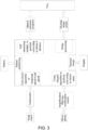
FIG. 3 illustrates a schematic view of an overall design framework of a support loop assembly of a telescope range finder based on thermal image wind-speed-noise according to an embodiment of the disclosure. - A first embodiment of the disclosure provides a telescope range finder based on thermal image-wind speed-noise, which includes a range finder body. One side of a top portion of the range finder body is provided with a wind speed measuring device, the other side of the top portion of the range finder body is provided with a measuring mode component, a front end of the range finder body is provided with a noise measuring device, and a side of the range finder body is provided with a thermal image display device.
- The wind speed measuring device includes a frame, gaps are disposed on the frame, a wind wheel 1 is disposed in the frame, the wind wheel 1 is connected to a tachometer, and the tachometer is connected to a processor in the range finder body.
- The processor is configured to: in response to rotating of the wind wheel 1, obtain a current wind speed according to the following calculation formula 1:

- where the rotational speed represents data obtained by the tachometer, and k and b represent wind speed calibration parameters;
- when 0 V < voltage ≤0.6 V, k= 11.2 and b = -0.72;
- when 0.6 V < voltage ≤1.5 V, k=10.3 and b = -0.18;
- when voltage > 1.5 V, k = 9.8 and b = 0.57.
- The noise measuring device includes a
microphone 11, and themicrophone 11 is connected to an amplification-filtering-rectification circuit. The amplification-filtering-rectification circuit is connected to the processor. Themicrophone 11 is configured to convert a noise into an electrical signal for entering the processor through the amplification-filtering-rectification circuit. The processor is configured to calculate a noise value of the noise, and a noise alarm value is set in the processor. - The thermal image display device includes a thermal image sensor, which is arranged in the range finder body. The thermal image sensor is connected to a
display 6 through the processor. Thedisplay 6 is disposed at the side of the range finder body, and thedisplay 6 is foldably connected to a surface of the range finder body. - A prey radiates an infrared thermal signal, which enter the thermal image sensor through a laser emitting
objective lens 2. A thermal image is collected by the thermal image sensor, then the collected thermal image is processed by the processor, and finally displayed on thedisplay 6. When a noise value obtained through calculating of a noise received by themicrophone 11 by the processor is greater than the noise alarm value set by the processor, thedisplay 6 flashes to remind the hunter that he in danger and he needs to escape quickly. - In an embodiment, the range finder body also includes an
eyepiece 10 with aneyepiece adjustment 9 thereon. Theeyepiece 10 is disposed at the front end of the range finder body, and an objective lens assembly is disposed at a rear end of the range finder body. Atop cover 4 is disposed on the range finder body, and thetop cover 4 is connected to ahousing 5 of the range finder body for sealing. - A diopter of the
eyepiece 10 can be adjusted through theeyepiece adjustment 9, so that different users can adjust the diopter based on their sights, and can see a distant situation in front clearly. There may be a display screen inside theeyepiece 10, which can display a aimed bull's-eye and measurement data. - The range finder body is also provided with a power supply assembly therein, the power supply assembly is configured to supply power to the whole of the telescope range finder. The power supply assembly includes a
charging interface 13, acharging indicator light 12, a lithium battery charged by thecharging interface 13 and a charging circuit. Thecharging interface 13 is configured to charge the lithium battery through the charging circuit. - When charging, a charging cable is connected to the
charging interface 13, if thecharging indicator light 12 is red, it means that the lithium battery is not fully charged, and if thecharging indicator light 12 is green, it means that the lithium battery is fully charged. - In an embodiment, the measurement mode component includes two modes, including a basic distance measurement mode and a shooting compensation distance measurement mode. The measurement mode component includes a power-on
measurement button 8 and amode switching button 7. The measurement mode component is connected to a time-of-flight (TOF) measurement module, and the TOF measurement module is connected to the processor and the objective lens assembly. - The user can select the basic distance measurement mode and the shooting compensation distance measurement mode by short pressing the
mode switching button 7, and can enter a setting menu by long pressing themode switching button 7; and the user can control the telescope range finder to perform distance measurement by pressing the power-onmeasurement button 8, for one-time distance measurement by short pressing, and for continuous measurement by long pressing the power-onmeasurement button 8. - In an embodiment, the objective lens assembly includes a laser emitting
objective lens 2 and a laser receivingobjective lens 3, and the TOF measuring module is configured to measure a distance measured by the laser emittingobjective lens 2 and the laser receivingobjective lens 3, internal code data of the TOF measuring module is read through the processor, and a target distance is calculated according to aformula 2 based on the internal code data;
- When the processor sends out a measurement instruction, the measurement instruction excites the laser transmitting
objective lens 2 to emit a laser to a prey, the laser is reflected and the reflected laser is received by the laser receivingobjective lens 3, and then the TOF measurement module performs measuring to obtain the distance. - In an embodiment, when the shooting compensation distance measurement mode is triggered by a user, a shooting compensation distance is obtained according to a
formula 3;
- k represents a shooting compensation coefficient, and m represent a proportional coefficient;
- when target distance ≤50 m, k=1.0 and m = 2506;
- when 50 m < target distance < target distance ≤200 m, k=1.06, and m = 8480;
- when 200 m < target distance < target distance ≤500 m, k=1.12, and m = 28,000;
- when target distance > 500 m, k=1.21, and m =61256.25.
- The second embodiment of the disclosure provides a ranging method of the telescope range finder based on thermal image-wind speed-noise described in the first embodiment, which includes the following steps:
- S1, when the telescope range finder is turned on, initializing, by the processor of the telescope range finder, parameters of the telescope range finder, and collecting, by the thermal image sensor, a thermal image in front of the telescope range finder, and displaying the thermal image on the
display 6 through the processor; - S2, selecting, by a user, a shooting compensation distance measurement mode or a basic distance measurement mode by triggering a mode switching button, to perform corresponding distance measurement, and to thereby obtain a target distance; and
- S3, obtaining, by the wind speed measuring device, the wind speed in a current environment, and obtaining a final to-be-measured distance based on the wind speed.
- In an embodiment, the parameters in S1 includes a working mode, a working frequency, a noise filtering parameter of a TOF measuring module, wind speed calibration parameters k and b, and a proportional coefficient m.
- In an embodiment, in S2, a step of obtaining the target distance includes:
- sending, by the processor, a measurement instruction to drive a laser emitting
objective lens 2 to emit a laser to a to-be-measured target, and to drive a laser receivingobjective lens 3 to receive a returned laser from the to-be-measured target; and - measuring, by a TOF measuring module, a distance measured by the laser emitting
objective lens 2 and the laser receivingobjective lens 3, reading internal code data of the TOF measuring module through the processor, and calculating the target distance based on the internal code data. - In an embodiment, the obtaining a final to-be-measured distance based on the wind speed in S3 includes:
- in a situation that the wind speed in the current environment does not affect a shooting trajectory, taking the obtained target distance as the final to-be-measured distance;
- in a situation that the wind speed in the current environment affects the shooting trajectory, calculating a shooting compensation distance based on the wind speed obtained by a wind wheel 1 and the target distance, and taking the shooting compensation distance as the final to-be-measured distance.
- In an embodiment, a screen of the
display 6 is configured to: in a situation that the noise value obtained through the electrical signal converted by themicrophone 11 is greater than the noise alarm value set by the processor, flash in the current environment based on the thermal image on thedisplay 6, to prompt a hunter to escape. - Basic concepts have been described above, and it is apparent that for those skilled in the art, the above detailed disclosure is merely exemplary, and does not constitute a limitation of this specification. Although it is not explicitly stated herein, those skilled in the art may make various modifications, improvements and offset treatments to the specification. Such modifications, improvements and offset treatments are suggested in this specification, and such modifications, improvements and offset treatments still belong to the spirit and scope of the exemplary embodiments of this specification.
- In addition, those skilled in the art can understand that various aspects of this specification can be illustrated and described by several patentable categories or situations, including any novel and useful process, machine, product or substance combination, or any novel and useful improvement thereof. Accordingly, various aspects of this specification can be completely executed by hardware, completely executed by software including firmware, resident software, and microcode, or executed by a combination of hardware and software. All the above hardware or software can be called "block", "module", "engine", "unit", "component" or "system". Furthermore, aspects of this specification may be embodied as a computer product in one or more computer-readable media, which includes computer-readable program code.
-
- 1
- Wind blade
- 2
- Laser emitting objective lens
- 3
- Laser receiving objective lens
- 4
- Top cover
- 5
- Housing
- 6
- Display
- 7
- Mode switching button
- 8
- Power-on measurement button
- 9
- Eyepiece adjustment
- 10
- Eyepiece
- 11
- Microphone
- 12
- Charging indicator light
- 13
- Charging interface
Claims (10)
- A telescope range finder based on thermal image-wind speed-noise, comprising a range finder body,wherein a side of a top portion of the range finder body is provided with a wind speed measuring device, another side of the top portion of the range finder body is provided with a measuring mode component, a front end of the range finder body is provided with a noise measuring device, and a side of the range finder body is provided with a thermal image display device;wherein the wind speed measuring device comprises a frame, gaps are disposed on the frame, a wind wheel (1) is disposed in the frame, the wind wheel (1) is connected to a tachometer, and the tachometer is connected to a processor in the range finder body;wherein the processor is configured to: in response to rotating of the wind wheel (1), obtain a wind speed at a current moment according to a formula 1:
 where the rotational speed represents data obtained by the tachometer, and k and b represent wind speed calibration parameters;wherein the noise measuring device comprises a microphone (11), the microphone (11) is connected to an amplification-filtering-rectification circuit, the amplification-filtering-rectification circuit is connected to the processor, the microphone (11) is configured to convert a noise into an electrical signal for entering the processor through the amplification-filtering- rectification circuit, the processor is configured to calculate a noise value of the noise, and a noise alarm value is set in the processor; andwherein the thermal image display device comprises a thermal image sensor, the thermal image sensor is disposed in the range finder body, the thermal image sensor is connected to a display (6) through the processor, the display (6) is disposed at the side of the range finder body, and the display (6) is foldably connected to a surface of the range finder body.
 - The telescope range finder based on thermal image-wind speed-noise as claimed in claim 1, wherein the range finder body further comprises an eyepiece (10) with an eyepiece adjustment (9) thereon, the eyepiece (10) is disposed at the front end of the range finder body, and an objective lens assembly is disposed at a rear end of the range finder body, a top cover (4) is disposed on the range finder body, and the top cover (4) is connected to a housing (5) of the range finder body for sealing;
wherein the range finder body is also provided with a power supply assembly therein, the power supply assembly is configured to supply power to the whole of the telescope range finder, the power supply assembly comprises a charging interface (13), a charging indicator light (12), a lithium battery charged by the charging interface (13), and a charging circuit; and the charging interface (13) is configured to charge the lithium battery through the charging circuit. - The telescope range finder based on thermal image-wind speed-noise as claimed in claim 2, wherein the measurement mode component has a basic distance measurement mode and a shooting compensation distance measurement mode, the measurement mode component comprises a power-on measurement button (8) and a mode switching button (7), the measurement mode component is connected to a time-of-flight (TOF) measurement module, and the TOF measurement module is connected to the processor and the objective lens assembly.
- The telescope range finder based on thermal image-wind speed-noise as claimed in claim 2 or 3, wherein the objective lens assembly comprises a laser emitting objective lens (2) and a laser receiving objective lens (3), the TOF measuring module is configured to measure a distance measured by the laser emitting objective lens (2) and the laser receiving objective lens (3), internal code data of the TOF measuring module is read through the processor, and a target distance is calculated according to a formula 2 based on the internal code data;

- The telescope range finder based on thermal image-wind speed-noise as claimed in claim 3, wherein when the shooting compensation distance measurement mode is triggered by a user, a shooting compensation distance is obtained according to a formula 3;

- A ranging method of the telescope range finder based on thermal image-wind speed-noise as claimed in any one of claims 1-5, comprising:S1, when the telescope range finder is turned on, initializing, by the processor of the telescope range finder, parameters of the telescope range finder, collecting, by the thermal image sensor, a thermal image in front of the telescope range finder, and displaying the thermal image on the display (6) through the processor;S2, selecting, by a user, a shooting compensation distance measurement mode or a basic distance measurement mode by triggering a mode switching button (7), to perform corresponding distance measurement, and to thereby obtain a target distance; andS3, obtaining, by the wind speed measuring device, the wind speed in a current environment, and obtaining a final to-be-measured distance based on the wind speed.
- The ranging method of the telescope range finder based on thermal image-wind speed-noise as claimed in claim 6, wherein the parameters in S1 comprises a working mode, a working frequency, a noise filtering parameter of a TOF measuring module, wind speed calibration parameters k and b, and a proportional coefficient m.
- The ranging method of the telescope range finder based on thermal image-wind speed-noise as claimed in claim 6 or 7, wherein in S2, a step of obtaining the target distance comprises:sending, by the processor, a measurement instruction to drive a laser emitting objective lens (2) to emit a laser to a to-be-measured target, and to drive a laser receiving objective lens (3) to receive a returned laser from the to-be-measured target; andmeasuring, by a TOF measuring module, a distance measured by the laser emitting objective lens (2) and the laser receiving objective lens (3), reading internal code data of the TOF measuring module through the processor, and calculating the target distance based on the internal code data.
- The ranging method of the telescope range finder based on thermal image-wind speed-noise as claimed in one of claims 6 to 8, wherein the obtaining a final to-be-measured distance based on the wind speed in S3 comprises:in a situation that the wind speed in the current environment does not affect a shooting trajectory, taking the target distance as the final to-be-measured distance;in a situation that the wind speed in the current environment affects the shooting trajectory, calculating a shooting compensation distance based on the wind speed obtained by a wind wheel (1) and the target distance, and taking the shooting compensation distance as the final to-be-measured distance.
- The ranging method of the telescope range finder based on thermal image-wind speed-noise as claimed in one of claims 6 to 9, wherein a screen of the display (6) is configured to: in a situation that the noise value obtained through the electrical signal converted by the microphone (11) is greater than the noise alarm value set by the processor, flash in the current environment based on the thermal image on the display (6), to prompt a hunter to escape.
Applications Claiming Priority (1)
| Application Number | Priority Date | Filing Date | Title |
|---|---|---|---|
| CN202211537449.2A CN115531845B (en) | 2022-12-02 | 2022-12-02 | Telescope range finder with thermosensitive wind speed and range finding method |
Publications (2)
| Publication Number | Publication Date |
|---|---|
| EP4379308A1 true EP4379308A1 (en) | 2024-06-05 |
| EP4379308B1 EP4379308B1 (en) | 2026-03-04 |
Family
ID=84722145
Family Applications (1)
| Application Number | Title | Priority Date | Filing Date |
|---|---|---|---|
| EP23204072.5A Active EP4379308B1 (en) | 2022-12-02 | 2023-10-17 | Telescope range finder based on thermal image-wind speed-noise and ranging method thereof |
Country Status (3)
| Country | Link |
|---|---|
| US (1) | US20240183638A1 (en) |
| EP (1) | EP4379308B1 (en) |
| CN (1) | CN115531845B (en) |
Families Citing this family (3)
| Publication number | Priority date | Publication date | Assignee | Title |
|---|---|---|---|---|
| CN115531845B (en) | 2022-12-02 | 2023-03-10 | 东莞市森威电子有限公司 | Telescope range finder with thermosensitive wind speed and range finding method |
| CN117593501B (en) * | 2023-11-24 | 2024-08-30 | 杭州隆硕科技有限公司 | Laser ranging telescope mode conversion method and system |
| TWI880643B (en) * | 2024-02-26 | 2025-04-11 | 亞洲光學股份有限公司 | Rangefinder with wireless charging function |
Citations (7)
| Publication number | Priority date | Publication date | Assignee | Title |
|---|---|---|---|---|
| US20040231220A1 (en) * | 2003-05-23 | 2004-11-25 | Mccormick Patrick | Trajectory compensating riflescope |
| US20140063261A1 (en) * | 2012-08-29 | 2014-03-06 | Pocket Optics, LLC | Portable distance measuring device with a laser range finder, image sensor(s) and microdisplay(s) |
| US20150369565A1 (en) * | 2014-06-20 | 2015-12-24 | Matthew Flint Kepler | Optical Device Having a Light Separation Element |
| US20160069644A1 (en) * | 2002-05-18 | 2016-03-10 | John Curtis Bell | Projectile sighting and launching control system |
| US20170115096A1 (en) * | 2015-10-26 | 2017-04-27 | Huntercraft Limited | Integrated Precise Photoelectric Sighting System |
| US20190377171A1 (en) * | 2018-06-12 | 2019-12-12 | Trackingpoint, Inc. | Analog-Digital Hybrid Firearm Scope |
| CN115531845B (en) | 2022-12-02 | 2023-03-10 | 东莞市森威电子有限公司 | Telescope range finder with thermosensitive wind speed and range finding method |
Family Cites Families (12)
| Publication number | Priority date | Publication date | Assignee | Title |
|---|---|---|---|---|
| CA2102442A1 (en) * | 1992-11-20 | 1994-05-21 | William Gobush | Method and apparatus to determine object striking instrument movement conditions |
| CN101428590A (en) * | 2008-08-13 | 2009-05-13 | 程滋颐 | Pick-up head for cars |
| CA2764120C (en) * | 2009-01-27 | 2019-01-08 | Xyz Interactive Technologies Inc. | A method and apparatus for ranging finding, orienting, and/or positioning of single and/or multiple devices |
| CN201378229Y (en) * | 2009-03-02 | 2010-01-06 | 重庆海珠光电科技有限公司 | Optical energy semiconductor laser ranging telescope |
| WO2011016892A2 (en) * | 2009-05-15 | 2011-02-10 | Michigan Aerospace Corporation | Range imaging lidar |
| EP2460034B1 (en) * | 2009-07-29 | 2015-09-09 | Michigan Aerospace Corporation | Atmospheric measurement system |
| US11002514B2 (en) * | 2018-04-13 | 2021-05-11 | Sheltered Wings, Inc. | Viewing optic with wind direction capture and method of using the same |
| US11804039B2 (en) * | 2020-05-28 | 2023-10-31 | Science House LLC | Systems, methods, and apparatus for enhanced cameras |
| US20220187448A1 (en) * | 2020-12-16 | 2022-06-16 | Waymo Llc | Adjusting Lidar Parameters Based on Environmental Conditions |
| JP7459779B2 (en) * | 2020-12-17 | 2024-04-02 | トヨタ自動車株式会社 | Sound source candidate extraction system and sound source exploration method |
| WO2023023200A1 (en) * | 2021-08-18 | 2023-02-23 | Maztech Industries, LLC | Weapon sight systems |
| FR3126248B1 (en) * | 2021-08-20 | 2023-07-28 | Ifp Energies Now | Method for determining wind speed using a laser remote sensing sensor mounted on a wind turbine |
-
2022
- 2022-12-02 CN CN202211537449.2A patent/CN115531845B/en active Active
-
2023
- 2023-09-12 US US18/465,175 patent/US20240183638A1/en active Pending
- 2023-10-17 EP EP23204072.5A patent/EP4379308B1/en active Active
Patent Citations (7)
| Publication number | Priority date | Publication date | Assignee | Title |
|---|---|---|---|---|
| US20160069644A1 (en) * | 2002-05-18 | 2016-03-10 | John Curtis Bell | Projectile sighting and launching control system |
| US20040231220A1 (en) * | 2003-05-23 | 2004-11-25 | Mccormick Patrick | Trajectory compensating riflescope |
| US20140063261A1 (en) * | 2012-08-29 | 2014-03-06 | Pocket Optics, LLC | Portable distance measuring device with a laser range finder, image sensor(s) and microdisplay(s) |
| US20150369565A1 (en) * | 2014-06-20 | 2015-12-24 | Matthew Flint Kepler | Optical Device Having a Light Separation Element |
| US20170115096A1 (en) * | 2015-10-26 | 2017-04-27 | Huntercraft Limited | Integrated Precise Photoelectric Sighting System |
| US20190377171A1 (en) * | 2018-06-12 | 2019-12-12 | Trackingpoint, Inc. | Analog-Digital Hybrid Firearm Scope |
| CN115531845B (en) | 2022-12-02 | 2023-03-10 | 东莞市森威电子有限公司 | Telescope range finder with thermosensitive wind speed and range finding method |
Also Published As
| Publication number | Publication date |
|---|---|
| CN115531845A (en) | 2022-12-30 |
| US20240183638A1 (en) | 2024-06-06 |
| CN115531845B (en) | 2023-03-10 |
| EP4379308B1 (en) | 2026-03-04 |
Similar Documents
| Publication | Publication Date | Title |
|---|---|---|
| EP4379308B1 (en) | Telescope range finder based on thermal image-wind speed-noise and ranging method thereof | |
| US11351436B2 (en) | Hybrid golf launch monitor | |
| US20070197314A1 (en) | Rangefinding devices and methods for golfing | |
| US7837572B2 (en) | Launch monitor | |
| US7053992B2 (en) | Rangefinder and method for collecting calibration data | |
| US7395696B2 (en) | Launch monitor | |
| US8500568B2 (en) | Launch monitor | |
| US7540500B2 (en) | Foldable launch monitor for golf | |
| US20120048931A1 (en) | System and method for the display of a ballestic trajectory adjusted reticule | |
| US20050282645A1 (en) | Launch monitor | |
| CN113203320A (en) | Simple fire control sighting device based on three lights | |
| NO332094B1 (en) | Method and system for fencing animals without the use of a physical fence | |
| CN108534603B (en) | Laser ranging night vision sighting telescope, anti-unmanned aerial vehicle net capturing gun and use method thereof | |
| US12276482B2 (en) | Method and system for sight target alignment | |
| CN101922894A (en) | Anti-sniper laser active detection system and method | |
| EP3655648A1 (en) | System recording the collisions of flying animals with wind turbines, its application and manner of recording collisions of flying animals with wind turbines with the use of the system | |
| CN115326049B (en) | A remote data acquisition system for antenna attitude based on NB-IOT | |
| CN110162735B (en) | A ballistic trajectory calculation method and system based on laser ranging telescope | |
| WO2020146577A1 (en) | Range finding display with power and angle indicators | |
| CN205067517U (en) | Laser velometer | |
| CN221099504U (en) | Active detection aiming system | |
| US20240053442A1 (en) | Laser Rangefinder | |
| CN205279883U (en) | A wrist formula indication of shots ware for shooting training aiding system | |
| US7982862B2 (en) | Line of sight wind speed detection system | |
| CN212723356U (en) | Laser ranging device with sensing device |
Legal Events
| Date | Code | Title | Description |
|---|---|---|---|
| PUAI | Public reference made under article 153(3) epc to a published international application that has entered the european phase |
Free format text: ORIGINAL CODE: 0009012 |
|
| STAA | Information on the status of an ep patent application or granted ep patent |
Free format text: STATUS: THE APPLICATION HAS BEEN PUBLISHED |
|
| AK | Designated contracting states |
Kind code of ref document: A1 Designated state(s): AL AT BE BG CH CY CZ DE DK EE ES FI FR GB GR HR HU IE IS IT LI LT LU LV MC ME MK MT NL NO PL PT RO RS SE SI SK SM TR |
|
| STAA | Information on the status of an ep patent application or granted ep patent |
Free format text: STATUS: REQUEST FOR EXAMINATION WAS MADE |
|
| 17P | Request for examination filed |
Effective date: 20241121 |
|
| RBV | Designated contracting states (corrected) |
Designated state(s): AL AT BE BG CH CY CZ DE DK EE ES FI FR GB GR HR HU IE IS IT LI LT LU LV MC ME MK MT NL NO PL PT RO RS SE SI SK SM TR |
|
| STAA | Information on the status of an ep patent application or granted ep patent |
Free format text: STATUS: EXAMINATION IS IN PROGRESS |
|
| 17Q | First examination report despatched |
Effective date: 20250122 |
|
| GRAP | Despatch of communication of intention to grant a patent |
Free format text: ORIGINAL CODE: EPIDOSNIGR1 |
|
| STAA | Information on the status of an ep patent application or granted ep patent |
Free format text: STATUS: GRANT OF PATENT IS INTENDED |
|
| INTG | Intention to grant announced |
Effective date: 20251121 |
|
| GRAS | Grant fee paid |
Free format text: ORIGINAL CODE: EPIDOSNIGR3 |
|
| GRAA | (expected) grant |
Free format text: ORIGINAL CODE: 0009210 |
|
| STAA | Information on the status of an ep patent application or granted ep patent |
Free format text: STATUS: THE PATENT HAS BEEN GRANTED |
|
| AK | Designated contracting states |
Kind code of ref document: B1 Designated state(s): AL AT BE BG CH CY CZ DE DK EE ES FI FR GB GR HR HU IE IS IT LI LT LU LV MC ME MK MT NL NO PL PT RO RS SE SI SK SM TR |
|
| REG | Reference to a national code |
Ref country code: CH Ref legal event code: F10 Free format text: ST27 STATUS EVENT CODE: U-0-0-F10-F00 (AS PROVIDED BY THE NATIONAL OFFICE) Effective date: 20260304 Ref country code: GB Ref legal event code: FG4D |
|
| REG | Reference to a national code |
Ref country code: IE Ref legal event code: FG4D |
|
| REG | Reference to a national code |
Ref country code: DE Ref legal event code: R096 Ref document number: 602023012923 Country of ref document: DE |
|
| PG25 | Lapsed in a contracting state [announced via postgrant information from national office to epo] |
Ref country code: RS Free format text: LAPSE BECAUSE OF FAILURE TO SUBMIT A TRANSLATION OF THE DESCRIPTION OR TO PAY THE FEE WITHIN THE PRESCRIBED TIME-LIMIT Effective date: 20260604 |
|
| PG25 | Lapsed in a contracting state [announced via postgrant information from national office to epo] |
Ref country code: ES Free format text: LAPSE BECAUSE OF FAILURE TO SUBMIT A TRANSLATION OF THE DESCRIPTION OR TO PAY THE FEE WITHIN THE PRESCRIBED TIME-LIMIT Effective date: 20260304 |
|
| REG | Reference to a national code |
Ref country code: NL Ref legal event code: MP Effective date: 20260304 |
|
| PG25 | Lapsed in a contracting state [announced via postgrant information from national office to epo] |
Ref country code: PL Free format text: LAPSE BECAUSE OF FAILURE TO SUBMIT A TRANSLATION OF THE DESCRIPTION OR TO PAY THE FEE WITHIN THE PRESCRIBED TIME-LIMIT Effective date: 20260304 |
|
| PG25 | Lapsed in a contracting state [announced via postgrant information from national office to epo] |
Ref country code: GR Free format text: LAPSE BECAUSE OF FAILURE TO SUBMIT A TRANSLATION OF THE DESCRIPTION OR TO PAY THE FEE WITHIN THE PRESCRIBED TIME-LIMIT Effective date: 20260605 |
|
| REG | Reference to a national code |
Ref country code: LT Ref legal event code: MG9D |
|
| PG25 | Lapsed in a contracting state [announced via postgrant information from national office to epo] |
Ref country code: LT Free format text: LAPSE BECAUSE OF FAILURE TO SUBMIT A TRANSLATION OF THE DESCRIPTION OR TO PAY THE FEE WITHIN THE PRESCRIBED TIME-LIMIT Effective date: 20260304 |
|
| PG25 | Lapsed in a contracting state [announced via postgrant information from national office to epo] |
Ref country code: NO Free format text: LAPSE BECAUSE OF FAILURE TO SUBMIT A TRANSLATION OF THE DESCRIPTION OR TO PAY THE FEE WITHIN THE PRESCRIBED TIME-LIMIT Effective date: 20260604 |
|
| PG25 | Lapsed in a contracting state [announced via postgrant information from national office to epo] |
Ref country code: SE Free format text: LAPSE BECAUSE OF FAILURE TO SUBMIT A TRANSLATION OF THE DESCRIPTION OR TO PAY THE FEE WITHIN THE PRESCRIBED TIME-LIMIT Effective date: 20260304 Ref country code: FI Free format text: LAPSE BECAUSE OF FAILURE TO SUBMIT A TRANSLATION OF THE DESCRIPTION OR TO PAY THE FEE WITHIN THE PRESCRIBED TIME-LIMIT Effective date: 20260304 |
|
| PG25 | Lapsed in a contracting state [announced via postgrant information from national office to epo] |
Ref country code: HR Free format text: LAPSE BECAUSE OF FAILURE TO SUBMIT A TRANSLATION OF THE DESCRIPTION OR TO PAY THE FEE WITHIN THE PRESCRIBED TIME-LIMIT Effective date: 20260304 |
|
| PG25 | Lapsed in a contracting state [announced via postgrant information from national office to epo] |
Ref country code: LV Free format text: LAPSE BECAUSE OF FAILURE TO SUBMIT A TRANSLATION OF THE DESCRIPTION OR TO PAY THE FEE WITHIN THE PRESCRIBED TIME-LIMIT Effective date: 20260304 |
|
| PG25 | Lapsed in a contracting state [announced via postgrant information from national office to epo] |
Ref country code: BG Free format text: LAPSE BECAUSE OF FAILURE TO SUBMIT A TRANSLATION OF THE DESCRIPTION OR TO PAY THE FEE WITHIN THE PRESCRIBED TIME-LIMIT Effective date: 20260304 |