EP4379248A1 - Coupling assembly, coupling system and links - Google Patents
Coupling assembly, coupling system and links Download PDFInfo
- Publication number
- EP4379248A1 EP4379248A1 EP23212059.2A EP23212059A EP4379248A1 EP 4379248 A1 EP4379248 A1 EP 4379248A1 EP 23212059 A EP23212059 A EP 23212059A EP 4379248 A1 EP4379248 A1 EP 4379248A1
- Authority
- EP
- European Patent Office
- Prior art keywords
- link
- coupling
- bonding
- arcuate
- pivot pin
- Prior art date
- Legal status (The legal status is an assumption and is not a legal conclusion. Google has not performed a legal analysis and makes no representation as to the accuracy of the status listed.)
- Granted
Links
Images





Classifications
-
- F—MECHANICAL ENGINEERING; LIGHTING; HEATING; WEAPONS; BLASTING
- F16—ENGINEERING ELEMENTS AND UNITS; GENERAL MEASURES FOR PRODUCING AND MAINTAINING EFFECTIVE FUNCTIONING OF MACHINES OR INSTALLATIONS; THERMAL INSULATION IN GENERAL
- F16L—PIPES; JOINTS OR FITTINGS FOR PIPES; SUPPORTS FOR PIPES, CABLES OR PROTECTIVE TUBING; MEANS FOR THERMAL INSULATION IN GENERAL
- F16L25/00—Construction or details of pipe joints not provided for in, or of interest apart from, groups F16L13/00 - F16L23/00
- F16L25/01—Construction or details of pipe joints not provided for in, or of interest apart from, groups F16L13/00 - F16L23/00 specially adapted for realising electrical conduction between the two pipe ends of the joint or between parts thereof
-
- F—MECHANICAL ENGINEERING; LIGHTING; HEATING; WEAPONS; BLASTING
- F16—ENGINEERING ELEMENTS AND UNITS; GENERAL MEASURES FOR PRODUCING AND MAINTAINING EFFECTIVE FUNCTIONING OF MACHINES OR INSTALLATIONS; THERMAL INSULATION IN GENERAL
- F16L—PIPES; JOINTS OR FITTINGS FOR PIPES; SUPPORTS FOR PIPES, CABLES OR PROTECTIVE TUBING; MEANS FOR THERMAL INSULATION IN GENERAL
- F16L21/00—Joints with sleeve or socket
- F16L21/06—Joints with sleeve or socket with a divided sleeve or ring clamping around the pipe ends
-
- F—MECHANICAL ENGINEERING; LIGHTING; HEATING; WEAPONS; BLASTING
- F16—ENGINEERING ELEMENTS AND UNITS; GENERAL MEASURES FOR PRODUCING AND MAINTAINING EFFECTIVE FUNCTIONING OF MACHINES OR INSTALLATIONS; THERMAL INSULATION IN GENERAL
- F16L—PIPES; JOINTS OR FITTINGS FOR PIPES; SUPPORTS FOR PIPES, CABLES OR PROTECTIVE TUBING; MEANS FOR THERMAL INSULATION IN GENERAL
- F16L17/00—Joints with packing adapted to sealing by fluid pressure
- F16L17/02—Joints with packing adapted to sealing by fluid pressure with sealing rings arranged between outer surface of pipe and inner surface of sleeve or socket
- F16L17/04—Joints with packing adapted to sealing by fluid pressure with sealing rings arranged between outer surface of pipe and inner surface of sleeve or socket with longitudinally split or divided sleeve
-
- F—MECHANICAL ENGINEERING; LIGHTING; HEATING; WEAPONS; BLASTING
- F16—ENGINEERING ELEMENTS AND UNITS; GENERAL MEASURES FOR PRODUCING AND MAINTAINING EFFECTIVE FUNCTIONING OF MACHINES OR INSTALLATIONS; THERMAL INSULATION IN GENERAL
- F16L—PIPES; JOINTS OR FITTINGS FOR PIPES; SUPPORTS FOR PIPES, CABLES OR PROTECTIVE TUBING; MEANS FOR THERMAL INSULATION IN GENERAL
- F16L23/00—Flanged joints
- F16L23/04—Flanged joints the flanges being connected by members tensioned in the radial plane
-
- F—MECHANICAL ENGINEERING; LIGHTING; HEATING; WEAPONS; BLASTING
- F16—ENGINEERING ELEMENTS AND UNITS; GENERAL MEASURES FOR PRODUCING AND MAINTAINING EFFECTIVE FUNCTIONING OF MACHINES OR INSTALLATIONS; THERMAL INSULATION IN GENERAL
- F16L—PIPES; JOINTS OR FITTINGS FOR PIPES; SUPPORTS FOR PIPES, CABLES OR PROTECTIVE TUBING; MEANS FOR THERMAL INSULATION IN GENERAL
- F16L23/00—Flanged joints
- F16L23/12—Flanged joints specially adapted for particular pipes
-
- F—MECHANICAL ENGINEERING; LIGHTING; HEATING; WEAPONS; BLASTING
- F16—ENGINEERING ELEMENTS AND UNITS; GENERAL MEASURES FOR PRODUCING AND MAINTAINING EFFECTIVE FUNCTIONING OF MACHINES OR INSTALLATIONS; THERMAL INSULATION IN GENERAL
- F16L—PIPES; JOINTS OR FITTINGS FOR PIPES; SUPPORTS FOR PIPES, CABLES OR PROTECTIVE TUBING; MEANS FOR THERMAL INSULATION IN GENERAL
- F16L23/00—Flanged joints
- F16L23/04—Flanged joints the flanges being connected by members tensioned in the radial plane
- F16L23/06—Flanged joints the flanges being connected by members tensioned in the radial plane connected by toggle-action levers
Definitions
- This disclosure relates to coupling assemblies for interconnecting confronting ends of a pair of fluid conveying members, and more particularly, clamshell variety coupling assembly, including methods of use.
- Couplings are often difficult to assemble and prone to failure.
- many do not form a tight seal between the pipe interior and ambient environment, thereby allowing the media to escape to the outside environment, or allowing the outside environment to contaminate the media.
- conventional couplings are difficult to install and assemble, thereby requiring expensive skilled artisans to construct the conduit system.
- a coupling assembly in one concept, includes a coupling body defined by first and second arcuate coupling members each having a first end and a second end; a hinge arrangement for pivotally connecting the second ends of the first and second arcuate coupling members together such that the first and second arcuate coupling members are pivotally moveable between an open position and a closed position, the first and second arcuate coupling members surrounding a central axis of the coupling body when in the closed position, the first and second arcuate coupling members defining a circumferential gap between the second ends, the hinge arrangement including first and second links that are parallel and that are spaced-apart from one another in an orientation along the central axis, the first and second links being configured to extend circumferentially across the gap, the first and second links being pivotally connected to the first arcuate coupling member at a first pivot axis and being pivotally connected to the second arcuate coupling member at a second pivot axis, the first link including a first bonding finger configured to project through the
- each of the first and second links includes parallel first and second link walls that extend between first and second link ends, the link walls define first pivot pin openings adjacent the first link ends and second pivot pin openings adjacent the second link ends, the first link end of the first link is connected to the first arcuate coupling member by a first pivot pin that extends along the first pivot axis and through the first pivot pin openings of the first link, the second link end of the first link is connected to the second arcuate coupling member by a second pivot pin that extends along the second pivot axis and through the second pivot pin openings of the first link, the first link end of the second link is connected to the first arcuate coupling member by a third pivot pin that extends along the first pivot axis and through the first pivot pin openings of the second link, the second link end of the second link is connected to the second arcuate coupling member by a fourth pivot pin that extends along the second pivot axis and through the second pivot pin openings of the second link and the first and second bonding fingers are defined
- each of the first and second links includes a bridge portion that couples the first and second link walls.
- the coupling body includes first and second axial ends, radial flanges are provide at the first and second axial ends, and bonding wires routed circumferentially within the coupling body within grooves defined by radial flanges, the bonding wires include a first bonding wire including circumferential portions routed circumferentially along the first arcuate coupling member at the first and second axial ends of the coupling body and a second bonding wire including circumferential portions routed circumferentially along second arcuate coupling member at the first and second axial ends of the coupling body, the first bonding wire includes an axial portion routed axially along the first arcuate coupling member between circumferential portions of the first bonding wire, and the second bonding wire includes an axial portion routed axially along the second arcuate coupling member between circumferential portions of the second bonding wire.
- the coupling assembly further includes a sleeve that fits within the coupling body, the first and second bonding fingers are adapted to contact the sleeve.
- a coupling system in one concept, includes a coupling assembly including a coupling body defined by first and second arcuate coupling members each having a first end and a second end; a hinge arrangement for pivotally connecting the second ends of the first and second arcuate coupling members together such that the first and second arcuate coupling members are pivotally moveable between an open position and a closed position, the first and second arcuate coupling members surrounding a central axis of the coupling body when in the closed position, the first and second arcuate coupling members defining a circumferential gap between the second ends, the hinge arrangement including first and second links that are parallel and that are spaced-apart from one another in an orientation along the central axis, the first and second links being configured to extend circumferentially across the gap, the first and second links being pivotally connected to the first arcuate coupling member at a first pivot axis and being pivotally connected to the second arcuate coupling member at a second pivot axis, the first link including a first bonding
- a link in one concept, includes a link body configured for at least a mechanical connection; and a bonding finger configured for at least an electrical bonding, the bonding finger couples to the link body.
- FIGS. 1-4 show a coupling system 10 including a coupling assembly 100 and a sleeve 112 that are both attached to a pair of fluid conveying members 108a,b.
- coupling system 10 can be part of a fluid conveying application, such as a low pressure aircraft fuel system.
- the coupling assembly 100 may be a threadless, clamshell variety.
- the coupling assembly 100 is configured to connect together a fluid joint that includes confronting ends of a pair of confronting fluid conveying members 108a,b, each end having a ferrule 110a,b attached to an end thereof, and a sleeve 112 that is installed over and surrounds the ferrules 110a,b.
- Each ferrule 110a,b includes an annular channel or groove 114a,b configured to receive an annular sealing member 116a,b, such as an O-ring.
- the sleeve 112 is generally cylindrical in shape and includes an inner cylindrical surface 118 and an outer cylindrical surface 120.
- the coupling operation begins with installing the annular sealing members 116a,b into respective grooves 114a,b in the ferrules 110a,b of the fluid conveying members 108a,b.
- the ferrules 110a,b of the fluid conveying members 108a,b are moved into a confronting position with each other, such that they are positioned in close proximity or contact with each other.
- the sleeve 112 is then installed over the ferrules 1 10a,b of the fluid conveying members 108a,b, such that the sleeve 112 surrounds the ferrules 110a,b.
- the ferrules 110a,b of the fluid conveying members 108a,b, which are surrounded by the sleeve 112, are then placed within one of the coupling members (e.g., first coupling member 102a), and the first and second coupling members 102a,b are rotated relative to each other towards the closed position of the coupling assembly 100.
- the coupling members e.g., first coupling member 102a
- the tubular first fluid conveying member 108a and the tubular second fluid conveying member 108b represent existing pipe sections to be joined.
- the first fluid conveying member 108a and second fluid conveying member 108b each have the outside diameter and the inside diameter.
- the first fluid conveying member 108a and second fluid conveying member 108b also have the pipe interior surface 130 and the pipe exterior surface 128.
- the first fluid conveying member 108a and second fluid conveying member 108b have the same outside diameter and the same inside diameter. It will be apparent to those of ordinary skill in the art that the typical application of the coupling assembly 100 will be for joining sections of the same inside and outside diameter, but the coupling assembly 100 may be altered to accommodate different pipe sizes. As shown in FIGS. 1 and 2 , the first fluid conveying member 108a and second fluid conveying member 108b share the longitudinal axis A.
- the axial gap between the first fluid conveying member 108a and second fluid conveying member 108b is designated. It will be understood that the axial gap may vary, depending, for example, on the outside diameter or the inside diameter.
- the first fluid conveying member 108a and second fluid conveying member 108b typically comprise the same material.
- the coupling assembly 100 may surround the two ends of the pair of fluid conveying members 108a,b and the axial gap between the two ends of the pair of fluid conveying members 108a,b.
- the coupling assembly 100 may have a generally circular or otherwise rounded shape configured to surround and conform to a contour or contours of the outer surfaces of the fluid conveying members 108a,b, and/or to other features in between the coupling assembly 100 and the fluid conveying members 108a,b. Although described primarily herein as having a generally circular or otherwise rounded shape, the coupling assembly 100 may have other shapes to conform to non-circular or non-rounded shapes or segments of the fluid conveying members 108a,b.
- portions of the outer surfaces of the fluid conveying members 108a,b are shown in dashed line underneath the coupling assembly 100 for clarity. As is discussed in further detail below, other features or structures may be located in between the coupling assembly 100 and the outer surfaces of the fluid conveying members 108a,b. For example, there may be a sleeve 112, a gasket or other types of seals in between the coupling assembly 100 and the fluid conveying members 108a,b.
- the coupling assembly 100 may be hinged together at one respective end via the hinge arrangement 104 and releasably secured together at the other respective end via the latching arrangement 106.
- the hinge arrangement 104 enables the first and second coupling members 102a,b to move relative to each other between a closed position of the first and second coupling members 102a,b ( FIG. 3 ), where the latching arrangement 106 is engaged and the first and second coupling members 102a,b are secured together as a single continuous annular unit, and an open position, where the latching arrangement 106 is disengaged and the first and second coupling members 102a,b are free to move relative to each other via the hinge arrangement 104.
- the latching arrangement 106 is further demounted from the first and second coupling members 102a,b to show the details. It is understandable that in open position of the first and second coupling members 102a,b, at least part of the latching arrangement 106 can be secured on at least one of the first and second coupling members 102a,b.
- the coupling body 102 In its closed position ( FIG. 3 ), the coupling body 102 defines a central longitudinal axis A.
- the first coupling member 102a defines a rotation axis B and the second coupling member 102b defines a rotation axis C, in some embodiments, at least one of the rotation axis B and rotation axis C is parallel to the central longitudinal axis A.
- FIGS. 5 through 11 depict various views of various embodiments of a coupling assembly 100 having first and second links 200a,b.
- the coupling assembly 100 may include a coupling body 102 which defined by first and second coupling members 102a,b, each first and second coupling members 102a,b having a first end 102c,d and a second end 102e,f.
- the coupling assembly 100 may include a hinge arrangement 104 for pivotally connecting the second end 102e,f of the first and second coupling members 102a,b together such that the first and second coupling members 102a,b are pivotally moveable between a closed position ( FIG. 3 ) and an open position ( FIG.
- first and second coupling members 102a,b surrounding a central axis A of the coupling body 102 when in the closed position, the first and second coupling members 102a,b defining a second circumferential gap 124c between the second end 102e,f.
- the coupling assembly 100 may be hinged together at one respective end via the hinge arrangement 104 and releasably secured together at the other respective end via the latching arrangement 106.
- the hinge arrangement 104 enables the first and second coupling members 102a,b to move relative to each other between a closed position ( FIG. 3 ), where the latching arrangement 106 is engaged and the first and second coupling members 102a,b are secured together as a single continuous annular unit, and an open position ( FIG. 4 ), where the latching arrangement 106 is disengaged and the first and second coupling members 102a,b are free to move relative to each other via the hinge arrangement 104.
- the coupling body 102 In its closed position ( FIG. 3 ), the coupling body 102 defines a central longitudinal axis A.
- the first coupling member 102a includes a first pair of parallel walls 1024a,c extend circumferentially on the outside surface of the first coupling member 102a
- the second coupling member 102b includes a second pair of parallel walls 1024b,d extend circumferentially on the outside surface of the second coupling member 102b.
- the hinge arrangement 104 may include first and second links 200a,b that are parallel and that are spaced-apart from one another in an orientation along the central axis A, the first and second links 200a,b being configured to extend circumferentially across the second circumferential gap 124c, the first and second links 200a,b being pivotally connected to the first pair of parallel walls 1024a,c at a first pivot axis B and being pivotally connected to the second pair of parallel walls 1024b,d at a second pivot axis C; and the latching arrangement 106 for latching the first end 102c,d of the first and second coupling members 102a,b together to latch the first and second coupling members 102a,b in the closed position having a first circumferential gap 124b.
- the coupling assembly combines the function of a hinging mechanism and an electrically bonding mechanism of the coupling assembly and the sleeve, therefore reduces part count of links 200a,b to a bare minimum of two. It improves the reliability and efficiency of the coupling assembly and reduces the manufacturing cost.
- the binding will remain operational both when the coupling assembly is in the open and closed position, ensuring that electrical and/or signal transmission between the fluid conveying members 108a,b is maintained at all times.
- the coupling assembly achieves electrical bonding via a second circumferential gap 124c between the first and second coupling members 102a,b, without interference with the first and second coupling members 102a,b.
- the first and second links 200a,b maintain the redundancy requirement of 14 CFR 25.981, which means that even if any of them fails, the remaining one will continue to work and fulfill its function.
- the latching arrangement 106 may lock or otherwise secure the first and second coupling members 102a,b together.
- the first and second links 200a,b may be used to bring together the first and second coupling members 102a,b of the coupling assembly 100 and tighten the coupling assembly 100 onto the two fluid conveying members 108a,b.
- the first and second links 200a,b may be coupled with the second end 102e,f.
- the first and second links 200a,b may therefore connect the second end 102e,f.
- the first and second links 200a,b may be adjustable so that the coupling assembly 100 can accommodate various sizes and/or shapes of fluid conveying members 108a,b.
- each of the first and second links 200a,b includes parallel first and second link walls 210a,b that extend between first and second link ends 220a,b, the first and second link walls 210a,b define first pivot pin openings 230a adjacent the first link ends 220a and second pivot pin openings 230b adjacent the second link ends 220b.
- first and second link walls 210a,b define first pivot pin openings 230a adjacent the first link ends 220a and second pivot pin openings 230b adjacent the second link ends 220b.
- the first link ends 220a of the first link 200a is connected to the first coupling member 102a by a first pivot pin 240a that extends along the first pivot axis B and through the first pivot pin openings 230a of the first link 200a and the first openings 1024a of the first coupling member 102a.
- the second link ends 220b of the first link 200a is connected to the second coupling member 102b by a second pivot pin 240b that extends along the second pivot axis C and through the second pivot pin openings 230b of the first link 200a and the second openings 1024b of the second coupling member 102b.
- first link ends 220a of the second link 200b is connected to the first coupling member 102a by a third pivot pin 240c that extends along the first pivot axis B and through the first pivot pin openings 230a of the second link 200b and the third openings 1024c of the first coupling member 102a.
- second link ends 220b of the second link 200b is connected to the second coupling member 102b by a fourth pivot pin 240d that extends along the second pivot axis C and through the second pivot pin openings 230b of the second link 200b and the fourth openings 1024d of the second coupling member 102b.
- the first and third openings 1024a,c defines the rotation axis B of the first coupling member 102a
- the second and fourth openings 1024b,d defines the rotation axis C of the first coupling member 102b.
- each pin has the same length and/or diameter.
- the diameters of pin ends 2404a,b,c,d of the pivot pins 240a,b,c,d increase as the pivot pin 240a,b,c,d extends axially. With such arrangement, the pivot pin is secured in its working position after passing through the opening of the coupling members, therefore holding the link in its working position.
- the pin ends 2404a,b,c,d of the pivot pin 240a,b,c,d is detachable from a body 2406a,b,c,d of the pivot pin, thus to facilitate the installation or removal of the link without dismantling the coupling assembly.
- the first and third pivot pin 240a,c can be connected via a first node 2402a, while the second and fourth pivot pin 240b,d can be connected via a second node 2402b.
- Such nodular connection makes it easier to connect the pins to each other, and provides buffering between the pins.
- the first coupling member 102a includes a third pair of parallel walls 1024e,g extend circumferentially on the outside surface of the first coupling member 102a
- the second coupling member 102b includes a fourth pair of parallel walls extend circumferentially on the outside surface of the second coupling member 102b.
- first and second bonding wires 330a,b is shown schematically.
- the coupling body 102 includes first and second axial ends 310a,b, radial flanges 320a,b are provide at the first and second axial ends 310a,b, and first and second bonding wires 330a,b routed circumferentially within the coupling body 102 within notches 322a,b defined by radial flanges 320a,b, the first and second bonding wires 330a,b include a first bonding wire 330a including first circumferential portions 332a routed circumferentially along the first coupling member 102a at the first and second axial ends 310a,b of the coupling body 102, and a second bonding wire 330b including second circumferential portions 332b routed circumferentially along second coupling member 102b at the first and second axial ends 310a,b of the coupling body 102, the first and second bonding wire 330a including first circumferential portions 3
- the radial flanges 320a,b may secure the connection and sealing between the coupling assembly 100 and the pair of fluid conveying members 108a,b, and the first and second bonding wires 330a,b provide the electrical connection between the pair of fluid conveying members 108a,b.
- at least one of the first and second circumferential portions 332a,b may also include several segments of lines based on designs, such as installation requirements.
- the first and second bonding wires 330a,b may also include radially portions and outer circumferential portions, as shown at least in FIGS. 14-17 .
- each of the links 200a,b includes a link body and a bonding finger.
- the first and second bonding fingers 202a,b are each defined by a resilient cantilever member 250 having has an end fixed to one of the first and second link walls 210a,b of each of the first and second links 200a,b.
- the resilient cantilever member 250 may include a cantilever body 252 and a hook 254.
- one end of the cantilever body 252 can be unitarily formed with the second link walls 210b.
- the hook 254 is, for example, fixed to an opposite end of the cantilever body 252 and located at a free end of the resilient cantilever member 250.
- the hook 254 can further enlarge the contact space between the first and second links 200a,b and the sleeve 112, and may also avoid, by its rounded shape, the physical damage to the sleeve 112 that could be caused by the contact. Therefore, the resilient cantilever members 250 may allow operation of the first and second bonding fingers 202a,b in different senses of motion.
- One sense of motion is the deflection of the resilient cantilever members 250 under impact loads applied at the free end of the first and second links 200a,b, thus securing the mechanical connection and the electrical bonding between the first and second links 200a,b and the sleeve 112.
- the angle P can be varied based on the distance between the first and second links 200a,b and the sleeve 112, such as ranging from 20°-60°. That is, the angle between the resilient cantilever members 250 and the second link wall 210b varies, for example, from 120°-160°. For example, the angle P might decrease when the distance between the first and second links 200a,b and the sleeve 112 increase, or the angle P might increase when the distance between the first and second links 200a,b and the sleeve 112 decrease. Thus, the mechanical connection and the electrical bonding between the first and second links 200a,b and the sleeve 112 is ensured.
- Such arrangement can be achieved by the flexible connection between the resilient cantilever member 250 and second link walls 210b.
- the length of the resilient cantilever members 250 can be varied based on the distance between the between the first and second links 200a,b and the sleeve 112 to secure the mechanical connection and the electrical bonding.
- each of the first and second links 200a,b includes a bridge portion 260 that couples the first and second link walls 210a,b.
- the bridge portion 260 may allow operation of the first and second links 200a,b in different senses of motion.
- One sense of motion is the deflection of the bridge portion 260 under impact loads applied at the first and second link walls 210a,b.
- Another sense of motion is the twisting of the first and second link walls 210a,b.
- the bridge portion 260 provide each of the first and second links 200a,b with the ability to withstand high impact loads and torsional loads, thus securing the mechanical connection and the electrical bonding between the first and second links 200a,b and the sleeve 112.
- the first link wall 210a includes a concave 280 located opposite to the bridge portion 260 to avoid potential contact between the link body and the bonding finger, especially when the link body and/or the bonding finger deflect.
Landscapes
- Engineering & Computer Science (AREA)
- General Engineering & Computer Science (AREA)
- Mechanical Engineering (AREA)
- Physics & Mathematics (AREA)
- Fluid Mechanics (AREA)
- Mutual Connection Of Rods And Tubes (AREA)
- Pivots And Pivotal Connections (AREA)
Abstract
Description
- This application claims priority to
U.S. Provisional Patent Application No. 63/428,378, titled "COUPLING ASSEMBLY, COUPLING SYSTEM AND LINKS," filed November 28, 2022 - This disclosure relates to coupling assemblies for interconnecting confronting ends of a pair of fluid conveying members, and more particularly, clamshell variety coupling assembly, including methods of use.
- Couplings are often difficult to assemble and prone to failure. In addition, many do not form a tight seal between the pipe interior and ambient environment, thereby allowing the media to escape to the outside environment, or allowing the outside environment to contaminate the media. In general, conventional couplings are difficult to install and assemble, thereby requiring expensive skilled artisans to construct the conduit system.
- In one concept, a coupling assembly is provided and includes a coupling body defined by first and second arcuate coupling members each having a first end and a second end; a hinge arrangement for pivotally connecting the second ends of the first and second arcuate coupling members together such that the first and second arcuate coupling members are pivotally moveable between an open position and a closed position, the first and second arcuate coupling members surrounding a central axis of the coupling body when in the closed position, the first and second arcuate coupling members defining a circumferential gap between the second ends, the hinge arrangement including first and second links that are parallel and that are spaced-apart from one another in an orientation along the central axis, the first and second links being configured to extend circumferentially across the gap, the first and second links being pivotally connected to the first arcuate coupling member at a first pivot axis and being pivotally connected to the second arcuate coupling member at a second pivot axis, the first link including a first bonding finger configured to project through the circumferential gap and the second link including a second bonding finger configured to project through the circumferential gap; and a latching arrangement for latching the first ends of the first and second arcuate coupling members together to latch the first and second arcuate coupling members in the closed position.
- In example implementations, each of the first and second links includes parallel first and second link walls that extend between first and second link ends, the link walls define first pivot pin openings adjacent the first link ends and second pivot pin openings adjacent the second link ends, the first link end of the first link is connected to the first arcuate coupling member by a first pivot pin that extends along the first pivot axis and through the first pivot pin openings of the first link, the second link end of the first link is connected to the second arcuate coupling member by a second pivot pin that extends along the second pivot axis and through the second pivot pin openings of the first link, the first link end of the second link is connected to the first arcuate coupling member by a third pivot pin that extends along the first pivot axis and through the first pivot pin openings of the second link, the second link end of the second link is connected to the second arcuate coupling member by a fourth pivot pin that extends along the second pivot axis and through the second pivot pin openings of the second link and the first and second bonding fingers are defined by resilient cantilever members having has ends unitarily formed with one of the first and second link walls of each of the first and second links.
- In example implementations, each of the first and second links includes a bridge portion that couples the first and second link walls.
- In example implementations, the coupling body includes first and second axial ends, radial flanges are provide at the first and second axial ends, and bonding wires routed circumferentially within the coupling body within grooves defined by radial flanges, the bonding wires include a first bonding wire including circumferential portions routed circumferentially along the first arcuate coupling member at the first and second axial ends of the coupling body and a second bonding wire including circumferential portions routed circumferentially along second arcuate coupling member at the first and second axial ends of the coupling body, the first bonding wire includes an axial portion routed axially along the first arcuate coupling member between circumferential portions of the first bonding wire, and the second bonding wire includes an axial portion routed axially along the second arcuate coupling member between circumferential portions of the second bonding wire.
- In an example embodiment, the coupling assembly further includes a sleeve that fits within the coupling body, the first and second bonding fingers are adapted to contact the sleeve.
- In one concept, a coupling system is provided and includes a coupling assembly including a coupling body defined by first and second arcuate coupling members each having a first end and a second end; a hinge arrangement for pivotally connecting the second ends of the first and second arcuate coupling members together such that the first and second arcuate coupling members are pivotally moveable between an open position and a closed position, the first and second arcuate coupling members surrounding a central axis of the coupling body when in the closed position, the first and second arcuate coupling members defining a circumferential gap between the second ends, the hinge arrangement including first and second links that are parallel and that are spaced-apart from one another in an orientation along the central axis, the first and second links being configured to extend circumferentially across the gap, the first and second links being pivotally connected to the first arcuate coupling member at a first pivot axis and being pivotally connected to the second arcuate coupling member at a second pivot axis, the first link including a first bonding finger configured to project through the circumferential gap and the second link including a second bonding finger configured to project through the circumferential gap; and a latching arrangement for latching the first ends of the first and second arcuate coupling members together to latch the first and second arcuate coupling members in the closed position; a sleeve that fits within the coupling body, the first and second bonding fingers are adapted to contact the sleeve.
- In one concept, a link is provided and includes a link body configured for at least a mechanical connection; and a bonding finger configured for at least an electrical bonding, the bonding finger couples to the link body.
- A variety of examples of desirable product features or methods are set forth in part in the description that follows, and in part will be apparent from the description, or may be learned by practicing various aspects of the disclosure. The aspects of the disclosure may relate to individual features as well as combinations of features. It is to be understood that both the foregoing general description and the following detailed description are explanatory only and are not restrictive of the claimed invention.
-
-
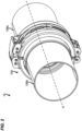
FIG. 1 is a schematic view of a coupling system including a coupling assembly and a sleeve, constructed in accordance with principles of this disclosure, depicting how a pair of fluid conveying members being interconnected. -
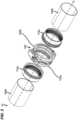
FIG. 2 is another schematic view of a coupling system including a coupling assembly and a sleeve, constructed in accordance with principles of this disclosure, depicting how a pair of fluid conveying members being interconnected. -
FIG. 3 is an exploded perspective view of one embodiment of a coupling assembly for interconnecting a pair of fluid conveying members, shown in a closed position of the first andsecond coupling members 102a,b. -
FIG. 4 is an exploded perspective view of one embodiment of a coupling assembly for interconnecting a pair of fluid conveying members, shown in an open position of the first andsecond coupling members 102a,b. -
FIG. 5 is a schematic view of a coupling assembly and a sleeve, constructed in accordance with principles of this disclosure, shown in a closed position of the first andsecond coupling members 102a,b. -
FIG. 6 is a front perspective view of the coupling assembly ofFIG. 5 . -
FIG. 7 is a top perspective view of the coupling assembly ofFIG. 5 . -
FIG. 8 is a bottom perspective view of the coupling assembly ofFIG. 5 . -
FIG. 9 is a side perspective view of the coupling assembly ofFIG. 5 . -
FIG. 10 is another side perspective view of the coupling assembly ofFIG. 5 , while asecond coupling member 102b is removed to show the details. -
FIG. 11 is an enlarge view of portion E shown inFIG. 10 , while asecond coupling member 102b is removed to show the details. -
FIG. 12 is another schematic view of the coupling assembly ofFIG. 5 . -
FIG. 13 is another schematic view of the coupling assembly ofFIG. 5 , in which part of thelatching arrangement 104 is removed to show the details. -
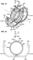
FIG. 14 is a schematic view of the coupling assembly, constructed in accordance with principles of this disclosure, shown in an open position of the first andsecond coupling members 102a,b. -
FIG. 15 is a front perspective view of the coupling assembly ofFIG. 14 . -
FIG. 16 is a top perspective view of the coupling assembly ofFIG. 14 . -
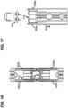
FIG. 17 is a side perspective view of the coupling assembly ofFIG. 14 . -
FIG. 18 is a schematic view of first andsecond links 200a,b including first andsecond bonding fingers 202a,b, constructed in accordance with principles of this disclosure. -
FIG. 19 is a front perspective view of the first andsecond links 200a,b ofFIG. 18 . -
FIG. 20 is a rear perspective view of the first andsecond links 200a,b ofFIG. 18 . -
FIG. 21 is a top perspective view of the first andsecond links 200a,b ofFIG. 18 . -
FIG. 22 is a bottom perspective view of the first andsecond links 200a,b ofFIG. 18 . -
FIG. 23 is a side perspective view of the first andsecond links 200a,b ofFIG. 18 . - Reference will now be made in detail to exemplary aspects of the present disclosure that are illustrated in the accompanying drawings. Wherever possible, the same reference numbers will be used throughout the drawings to refer to the same or like parts.
-
FIGS. 1-4 show acoupling system 10 including acoupling assembly 100 and asleeve 112 that are both attached to a pair offluid conveying members 108a,b. In one nonlimiting example,coupling system 10 can be part of a fluid conveying application, such as a low pressure aircraft fuel system. In this example, thecoupling assembly 100 may be a threadless, clamshell variety. - The
coupling assembly 100 is configured to connect together a fluid joint that includes confronting ends of a pair of confrontingfluid conveying members 108a,b, each end having aferrule 110a,b attached to an end thereof, and asleeve 112 that is installed over and surrounds theferrules 110a,b. Eachferrule 110a,b includes an annular channel orgroove 114a,b configured to receive anannular sealing member 116a,b, such as an O-ring. Thesleeve 112 is generally cylindrical in shape and includes an innercylindrical surface 118 and an outercylindrical surface 120. To couple the fluid joint having confronting ends of a pair of fluid conveying members, the coupling operation begins with installing theannular sealing members 116a,b intorespective grooves 114a,b in theferrules 110a,b of thefluid conveying members 108a,b. Next, theferrules 110a,b of thefluid conveying members 108a,b are moved into a confronting position with each other, such that they are positioned in close proximity or contact with each other. Thesleeve 112 is then installed over the ferrules 1 10a,b of thefluid conveying members 108a,b, such that thesleeve 112 surrounds theferrules 110a,b. Theferrules 110a,b of thefluid conveying members 108a,b, which are surrounded by thesleeve 112, are then placed within one of the coupling members (e.g.,first coupling member 102a), and the first andsecond coupling members 102a,b are rotated relative to each other towards the closed position of thecoupling assembly 100. - The tubular first
fluid conveying member 108a and the tubular secondfluid conveying member 108b represent existing pipe sections to be joined. The firstfluid conveying member 108a and secondfluid conveying member 108b each have the outside diameter and the inside diameter. The firstfluid conveying member 108a and secondfluid conveying member 108b also have thepipe interior surface 130 and thepipe exterior surface 128. Typically, the firstfluid conveying member 108a and secondfluid conveying member 108b have the same outside diameter and the same inside diameter. It will be apparent to those of ordinary skill in the art that the typical application of thecoupling assembly 100 will be for joining sections of the same inside and outside diameter, but thecoupling assembly 100 may be altered to accommodate different pipe sizes. As shown inFIGS. 1 and2 , the firstfluid conveying member 108a and secondfluid conveying member 108b share the longitudinal axis A. - The axial gap between the first
fluid conveying member 108a and secondfluid conveying member 108b is designated. It will be understood that the axial gap may vary, depending, for example, on the outside diameter or the inside diameter. The firstfluid conveying member 108a and secondfluid conveying member 108b typically comprise the same material. - The
coupling assembly 100 may surround the two ends of the pair offluid conveying members 108a,b and the axial gap between the two ends of the pair offluid conveying members 108a,b. Thecoupling assembly 100 may have a generally circular or otherwise rounded shape configured to surround and conform to a contour or contours of the outer surfaces of thefluid conveying members 108a,b, and/or to other features in between thecoupling assembly 100 and thefluid conveying members 108a,b. Although described primarily herein as having a generally circular or otherwise rounded shape, thecoupling assembly 100 may have other shapes to conform to non-circular or non-rounded shapes or segments of thefluid conveying members 108a,b. Portions of the outer surfaces of thefluid conveying members 108a,b are shown in dashed line underneath thecoupling assembly 100 for clarity. As is discussed in further detail below, other features or structures may be located in between thecoupling assembly 100 and the outer surfaces of thefluid conveying members 108a,b. For example, there may be asleeve 112, a gasket or other types of seals in between thecoupling assembly 100 and thefluid conveying members 108a,b. - Still in reference to
FIG. 1 , in some embodiments, thecoupling assembly 100 may be hinged together at one respective end via thehinge arrangement 104 and releasably secured together at the other respective end via the latchingarrangement 106. Thehinge arrangement 104 enables the first andsecond coupling members 102a,b to move relative to each other between a closed position of the first andsecond coupling members 102a,b (FIG. 3 ), where the latchingarrangement 106 is engaged and the first andsecond coupling members 102a,b are secured together as a single continuous annular unit, and an open position, where the latchingarrangement 106 is disengaged and the first andsecond coupling members 102a,b are free to move relative to each other via thehinge arrangement 104. InFIG.4 , based on the open position of the first andsecond coupling members 102a,b, the latchingarrangement 106 is further demounted from the first andsecond coupling members 102a,b to show the details. It is understandable that in open position of the first andsecond coupling members 102a,b, at least part of the latchingarrangement 106 can be secured on at least one of the first andsecond coupling members 102a,b. In its closed position (FIG. 3 ), thecoupling body 102 defines a central longitudinal axis A. Thefirst coupling member 102a defines a rotation axis B and thesecond coupling member 102b defines a rotation axis C, in some embodiments, at least one of the rotation axis B and rotation axis C is parallel to the central longitudinal axis A. -
FIGS. 5 through 11 depict various views of various embodiments of acoupling assembly 100 having first andsecond links 200a,b. In reference now toFIGS. 5-11 , in some embodiments, thecoupling assembly 100 may include acoupling body 102 which defined by first andsecond coupling members 102a,b, each first andsecond coupling members 102a,b having afirst end 102c,d and asecond end 102e,f. Thecoupling assembly 100 may include ahinge arrangement 104 for pivotally connecting thesecond end 102e,f of the first andsecond coupling members 102a,b together such that the first andsecond coupling members 102a,b are pivotally moveable between a closed position (FIG. 3 ) and an open position (FIG. 4 ), the first andsecond coupling members 102a,b surrounding a central axis A of thecoupling body 102 when in the closed position, the first andsecond coupling members 102a,b defining a secondcircumferential gap 124c between thesecond end 102e,f. - In some embodiments, the
coupling assembly 100 may be hinged together at one respective end via thehinge arrangement 104 and releasably secured together at the other respective end via the latchingarrangement 106. Thehinge arrangement 104 enables the first andsecond coupling members 102a,b to move relative to each other between a closed position (FIG. 3 ), where the latchingarrangement 106 is engaged and the first andsecond coupling members 102a,b are secured together as a single continuous annular unit, and an open position (FIG. 4 ), where the latchingarrangement 106 is disengaged and the first andsecond coupling members 102a,b are free to move relative to each other via thehinge arrangement 104. In its closed position (FIG. 3 ), thecoupling body 102 defines a central longitudinal axis A. - The
first coupling member 102a includes a first pair ofparallel walls 1024a,c extend circumferentially on the outside surface of thefirst coupling member 102a, and thesecond coupling member 102b includes a second pair ofparallel walls 1024b,d extend circumferentially on the outside surface of thesecond coupling member 102b. Thehinge arrangement 104 may include first andsecond links 200a,b that are parallel and that are spaced-apart from one another in an orientation along the central axis A, the first andsecond links 200a,b being configured to extend circumferentially across the secondcircumferential gap 124c, the first andsecond links 200a,b being pivotally connected to the first pair ofparallel walls 1024a,c at a first pivot axis B and being pivotally connected to the second pair ofparallel walls 1024b,d at a second pivot axis C; and the latchingarrangement 106 for latching thefirst end 102c,d of the first andsecond coupling members 102a,b together to latch the first andsecond coupling members 102a,b in the closed position having a firstcircumferential gap 124b. In some embodiments, thefirst link 200a including afirst bonding finger 202a configured to project axially through the secondcircumferential gap 124c and the second link 200b including asecond bonding finger 202b configured to project axially through the secondcircumferential gap 124c. Thus, the coupling assembly combines the function of a hinging mechanism and an electrically bonding mechanism of the coupling assembly and the sleeve, therefore reduces part count oflinks 200a,b to a bare minimum of two. It improves the reliability and efficiency of the coupling assembly and reduces the manufacturing cost. In addition, the binding will remain operational both when the coupling assembly is in the open and closed position, ensuring that electrical and/or signal transmission between the fluid conveyingmembers 108a,b is maintained at all times. Furthermore, the coupling assembly achieves electrical bonding via a secondcircumferential gap 124c between the first andsecond coupling members 102a,b, without interference with the first andsecond coupling members 102a,b. The first andsecond links 200a,b maintain the redundancy requirement of 14 CFR 25.981, which means that even if any of them fails, the remaining one will continue to work and fulfill its function. - The latching
arrangement 106 may lock or otherwise secure the first andsecond coupling members 102a,b together. The first andsecond links 200a,b may be used to bring together the first andsecond coupling members 102a,b of thecoupling assembly 100 and tighten thecoupling assembly 100 onto the twofluid conveying members 108a,b. As shown, the first andsecond links 200a,b may be coupled with thesecond end 102e,f. The first andsecond links 200a,b may therefore connect thesecond end 102e,f. As is further discussed in detail below, the first andsecond links 200a,b may be adjustable so that thecoupling assembly 100 can accommodate various sizes and/or shapes offluid conveying members 108a,b. The first andsecond links 200a,b may have a substantially shorter length as compared to that of thecoupling body 102. In some embodiments, the length of the first andsecond links 200a,b may be longer. Further, the first andsecond links 200a,b may have a width similar to that of thecoupling body 102. In some embodiments, the first andsecond links 200a,b may be narrower or wider than that of thecoupling body 102. - In reference at least to
FIGS. 8 ,11 ,12 and18 , an example embodiment of a latchingarrangement 106 is shown schematically. In some embodiments, at least inFIGS. 11-12 and18 , each of the first andsecond links 200a,b includes parallel first andsecond link walls 210a,b that extend between first and second link ends 220a,b, the first andsecond link walls 210a,b define firstpivot pin openings 230a adjacent the first link ends 220a and secondpivot pin openings 230b adjacent the second link ends 220b. In some embodiments, at least inFIG. 8 , the first link ends 220a of thefirst link 200a is connected to thefirst coupling member 102a by a first pivot pin 240a that extends along the first pivot axis B and through the firstpivot pin openings 230a of thefirst link 200a and thefirst openings 1024a of thefirst coupling member 102a. In some embodiments, the second link ends 220b of thefirst link 200a is connected to thesecond coupling member 102b by asecond pivot pin 240b that extends along the second pivot axis C and through the secondpivot pin openings 230b of thefirst link 200a and thesecond openings 1024b of thesecond coupling member 102b. In some embodiments, the first link ends 220a of the second link 200b is connected to thefirst coupling member 102a by athird pivot pin 240c that extends along the first pivot axis B and through the firstpivot pin openings 230a of the second link 200b and thethird openings 1024c of thefirst coupling member 102a. In some embodiments, the second link ends 220b of the second link 200b is connected to thesecond coupling member 102b by afourth pivot pin 240d that extends along the second pivot axis C and through the secondpivot pin openings 230b of the second link 200b and thefourth openings 1024d of thesecond coupling member 102b. In some embodiments, the first andthird openings 1024a,c defines the rotation axis B of thefirst coupling member 102a, and the second andfourth openings 1024b,d defines the rotation axis C of thefirst coupling member 102b. In some embodiments, for example inFIG. 11 , each pin has the same length and/or diameter. In some embodiments, for example inFIG. 11 , the diameters of pin ends 2404a,b,c,d of the pivot pins 240a,b,c,d increase as the pivot pin 240a,b,c,d extends axially. With such arrangement, the pivot pin is secured in its working position after passing through the opening of the coupling members, therefore holding the link in its working position. In some embodiments, for example inFIG. 11 , the pin ends 2404a,b,c,d of the pivot pin 240a,b,c,d is detachable from a body 2406a,b,c,d of the pivot pin, thus to facilitate the installation or removal of the link without dismantling the coupling assembly. In some embodiments, for example inFIGS. 8 and11 , the first and third pivot pin 240a,c can be connected via afirst node 2402a, while the second andfourth pivot pin 240b,d can be connected via asecond node 2402b. Such nodular connection makes it easier to connect the pins to each other, and provides buffering between the pins. In some embodiments, for example inFIGS. 8 and11 , thefirst coupling member 102a includes a third pair ofparallel walls 1024e,g extend circumferentially on the outside surface of thefirst coupling member 102a, and thesecond coupling member 102b includes a fourth pair of parallel walls extend circumferentially on the outside surface of thesecond coupling member 102b. Thus, the working position of the pivot pins is further secured, and the pins and the link attached will not be displaced even if they are subjected to external forces during operation. - In reference to
FIGS. 14-17 , an example embodiment of first andsecond bonding wires 330a,b is shown schematically. In some embodiments, thecoupling body 102 includes first and second axial ends 310a,b,radial flanges 320a,b are provide at the first and second axial ends 310a,b, and first andsecond bonding wires 330a,b routed circumferentially within thecoupling body 102 withinnotches 322a,b defined byradial flanges 320a,b, the first andsecond bonding wires 330a,b include afirst bonding wire 330a including firstcircumferential portions 332a routed circumferentially along thefirst coupling member 102a at the first and second axial ends 310a,b of thecoupling body 102, and asecond bonding wire 330b including secondcircumferential portions 332b routed circumferentially alongsecond coupling member 102b at the first and second axial ends 310a,b of thecoupling body 102, thefirst bonding wire 330a includes a firstaxial portion 334a routed axially along thefirst coupling member 102a between firstcircumferential portions 332a of thefirst bonding wire 330a, and thesecond bonding wire 330b includes a secondaxial portion 334b routed axially along thesecond coupling member 102b between secondcircumferential portions 332b of thesecond bonding wire 330b. As a result, theradial flanges 320a,b may secure the connection and sealing between thecoupling assembly 100 and the pair offluid conveying members 108a,b, and the first andsecond bonding wires 330a,b provide the electrical connection between the pair offluid conveying members 108a,b. In some embodiments, at least one of the first and secondcircumferential portions 332a,b may also include several segments of lines based on designs, such as installation requirements. In some embodiments, the first andsecond bonding wires 330a,b may also include radially portions and outer circumferential portions, as shown at least inFIGS. 14-17 . - In reference now to
FIGS. 18-23 , an example embodiment oflinks 200a,b is shown schematically. In some embodiments, each of thelinks 200a,b includes a link body and a bonding finger. In some embodiments, the first andsecond bonding fingers 202a,b are each defined by aresilient cantilever member 250 having has an end fixed to one of the first andsecond link walls 210a,b of each of the first andsecond links 200a,b. Theresilient cantilever member 250 may include acantilever body 252 and ahook 254. For example inFIG. 18 , one end of thecantilever body 252 can be unitarily formed with thesecond link walls 210b. Thehook 254 is, for example, fixed to an opposite end of thecantilever body 252 and located at a free end of theresilient cantilever member 250. Thehook 254 can further enlarge the contact space between the first andsecond links 200a,b and thesleeve 112, and may also avoid, by its rounded shape, the physical damage to thesleeve 112 that could be caused by the contact. Therefore, theresilient cantilever members 250 may allow operation of the first andsecond bonding fingers 202a,b in different senses of motion. One sense of motion is the deflection of theresilient cantilever members 250 under impact loads applied at the free end of the first andsecond links 200a,b, thus securing the mechanical connection and the electrical bonding between the first andsecond links 200a,b and thesleeve 112. - In some embodiments, the angle P can be varied based on the distance between the first and
second links 200a,b and thesleeve 112, such as ranging from 20°-60°. That is, the angle between theresilient cantilever members 250 and thesecond link wall 210b varies, for example, from 120°-160°. For example, the angle P might decrease when the distance between the first andsecond links 200a,b and thesleeve 112 increase, or the angle P might increase when the distance between the first andsecond links 200a,b and thesleeve 112 decrease. Thus, the mechanical connection and the electrical bonding between the first andsecond links 200a,b and thesleeve 112 is ensured. Such arrangement can be achieved by the flexible connection between theresilient cantilever member 250 andsecond link walls 210b. In some embodiments, the length of theresilient cantilever members 250 can be varied based on the distance between the between the first andsecond links 200a,b and thesleeve 112 to secure the mechanical connection and the electrical bonding. - Still in reference to
FIGS. 18-23 , in some embodiments, each of the first andsecond links 200a,b includes abridge portion 260 that couples the first andsecond link walls 210a,b. Here, thebridge portion 260 may allow operation of the first andsecond links 200a,b in different senses of motion. One sense of motion is the deflection of thebridge portion 260 under impact loads applied at the first andsecond link walls 210a,b. Another sense of motion is the twisting of the first andsecond link walls 210a,b. Thus, thebridge portion 260 provide each of the first andsecond links 200a,b with the ability to withstand high impact loads and torsional loads, thus securing the mechanical connection and the electrical bonding between the first andsecond links 200a,b and thesleeve 112. In some embodiments, thefirst link wall 210a includes a concave 280 located opposite to thebridge portion 260 to avoid potential contact between the link body and the bonding finger, especially when the link body and/or the bonding finger deflect. - Aspect 1. A coupling assembly comprising:
- a coupling body defined by first and second arcuate coupling members each having a first end and a second end;
- a hinge arrangement for pivotally connecting the second ends of the first and second arcuate coupling members together such that the first and second arcuate coupling members are pivotally moveable between an open position and a closed position, the first and second arcuate coupling members surrounding a central axis of the coupling body when in the closed position, the first and second arcuate coupling members defining a circumferential gap between the second ends, the hinge arrangement including first and second links that are parallel and that are spaced-apart from one another in an orientation along the central axis, the first and second links being configured to extend circumferentially across the circumferential gap, the first and second links being pivotally connected to the first arcuate coupling member at a first pivot axis and being pivotally connected to the second arcuate coupling member at a second pivot axis, the first link including a first bonding finger configured to project through the circumferential gap and the second link including a second bonding finger configured to project through the circumferential gap; and
- a latching arrangement for latching the first ends of the first and second arcuate coupling members together to latch the first and second arcuate coupling members in the closed position.
-
Aspect 2. The coupling assembly of Aspect 1, wherein each of the first and second links includes parallel first and second link walls that extend between first and second link ends, wherein the link walls define first pivot pin openings adjacent the first link ends and second pivot pin openings adjacent the second link ends, wherein the first link end of the first link is connected to the first arcuate coupling member by a first pivot pin that extends along the first pivot axis and through the first pivot pin openings of the first link, wherein the second link end of the first link is connected to the second arcuate coupling member by a second pivot pin that extends along the second pivot axis and through the second pivot pin openings of the first link, wherein the first link end of the second link is connected to the first arcuate coupling member by a third pivot pin that extends along the first pivot axis and through the first pivot pin openings of the second link, wherein the second link end of the second link is connected to the second arcuate coupling member by a fourth pivot pin that extends along the second pivot axis and through the second pivot pin openings of the second link and wherein the first and second bonding fingers are defined by resilient cantilever members having has ends unitarily formed with one of the first and second link walls of each of the first and second links. - Aspect 3. The coupling assembly of
Aspect 2, wherein each of the first and second links includes a bridge portion that couples the first and second link walls. - Aspect 4. The coupling assembly of Aspect 1, wherein the coupling body includes first and second axial ends, wherein radial flanges are provide at the first and second axial ends, and wherein bonding wires routed circumferentially within the coupling body within grooves defined by radial flanges, wherein the bonding wires include a first bonding wire including circumferential portions routed circumferentially along the first arcuate coupling member at the first and second axial ends of the coupling body and a second bonding wire including circumferential portions routed circumferentially along second arcuate coupling member at the first and second axial ends of the coupling body, wherein the first bonding wire includes an axial portion routed axially along the first arcuate coupling member between circumferential portions of the first bonding wire, and wherein the second bonding wire includes an axial portion routed axially along the second arcuate coupling member between circumferential portions of the second bonding wire.
- Aspect 5. A coupling system comprising:
- a coupling assembly including:
- a coupling body defined by first and second arcuate coupling members each having a first end and a second end;
- a hinge arrangement for pivotally connecting the second ends of the first and second arcuate coupling members together such that the first and second arcuate coupling members are pivotally moveable between an open position and a closed position, the first and second arcuate coupling members surrounding a central axis of the coupling body when in the closed position, the first and second arcuate coupling members defining a circumferential gap between the second ends, the hinge arrangement including first and second links that are parallel and that are spaced-apart from one another in an orientation along the central axis, the first and second links being configured to extend circumferentially across the gap, the first and second links being pivotally connected to the first arcuate coupling member at a first pivot axis and being pivotally connected to the second arcuate coupling member at a second pivot axis, the first link including a first bonding finger configured to project through the circumferential gap and the second link including a second bonding finger configured to project through the circumferential gap; and
- a latching arrangement for latching the first ends of the first and second arcuate coupling members together to latch the first and second arcuate coupling members in the closed position; and
- a sleeve that fits within the coupling body, wherein the first and second bonding fingers are adapted to contact the sleeve.
- Aspect 6. The coupling system of Aspect 5, wherein each of the first and second links includes parallel first and second link walls that extend between first and second link ends, wherein the link walls define first pivot pin openings adjacent the first link ends and second pivot pin openings adjacent the second link ends, wherein the first link end of the first link is connected to the first arcuate coupling member by a first pivot pin that extends along the first pivot axis and through the first pivot pin openings of the first link, wherein the second link end of the first link is connected to the second arcuate coupling member by a second pivot pin that extends along the second pivot axis and through the second pivot pin openings of the first link, wherein the first link end of the second link is connected to the first arcuate coupling member by a third pivot pin that extends along the first pivot axis and through the first pivot pin openings of the second link, wherein the second link end of the second link is connected to the second arcuate coupling member by a fourth pivot pin that extends along the second pivot axis and through the second pivot pin openings of the second link and wherein the first and second bonding fingers are defined by resilient cantilever members having has ends unitarily formed with one of the first and second link walls of each of the first and second links.
- Aspect 7. The coupling system of Aspect 6, wherein each of the first and second links includes a bridge portion that couples the first and second link walls.
- Aspect 8. The coupling system of Aspect 5, wherein the coupling body includes first and second axial ends, wherein radial flanges are provide at the first and second axial ends, and wherein bonding wires routed circumferentially within the coupling body within grooves defined by radial flanges, wherein the bonding wires include a first bonding wire including circumferential portions routed circumferentially along the first arcuate coupling member at the first and second axial ends of the coupling body and a second bonding wire including circumferential portions routed circumferentially along second arcuate coupling member at the first and second axial ends of the coupling body, wherein the first bonding wire includes an axial portion routed axially along the first arcuate coupling member between circumferential portions of the first bonding wire, and wherein the second bonding wire includes an axial portion routed axially along the second arcuate coupling member between circumferential portions of the second bonding wire.
- Aspect 9. A link comprising:
- a link body configured for at least a mechanical connection; and
- a bonding finger configured for at least an electrical bonding, wherein the bonding finger couples to the link body.
-
Aspect 10. The link of Aspect 9, wherein the link body includes at least one link wall. - Aspect 11. The link of
Aspect 10, wherein the link body includes a first link wall and a second link wall, the link body further includes a bridge portion that couples to the first and second link walls. - Aspect 12. The link of Aspect 11, wherein the first and second link walls parallel to each other.
- Aspect 13. The link of Aspect 11, wherein the first and second link walls each has at least one pivot pin opening, the pivot pin opening is configured for the mechanical connection.
- Aspect 14. The link of
Aspect 10, wherein the bonding finger is defined by a resilient cantilever member having an end, the end is configured to be connected to at least one of the first and second link walls. - Aspect 15. The link of Aspect 14, wherein the angle between the resilient cantilever member and the one of the at least one link wall is greater than 90°.
- Aspect 16. The link of Aspect 14, wherein the angle between the resilient cantilever member and the one of the at least one link wall is between 120°and 160°.
- Aspect 17. The link of Aspect 14, wherein the resilient cantilever member further includes a hook-shaped free end.
- Aspect 18. The link of Aspect 14, wherein the resilient cantilever member is configured for the electrical bonding.
- Aspect 19. The link of Aspect 14, wherein the bonding finger is unitarily formed with the link body.
- Aspect 20. The link of Aspect 9, wherein the link body is configured for the electrical bonding.
- Aspect 21. The link of any of the above Aspects, wherein the link is incorporated as part of a hinge of a clam-shell style clamp.
- Aspect 22. The link of Aspect 21, wherein the bonding finger is configured to extend through a circumferential gap between arcuate coupling members that are pivotally coupled together by the hinge.
- Aspect 23. The link of Aspect 21, wherein the clam-shell style clamp is part of a coupling system for coupling together fluid conveying members having ends with ferrules that fit within the clamp.
- Aspect 24. The link of aspect 23, wherein the coupling system includes a sleeve that fits within the clamp and fits over the ferrules, wherein the bonding finger electrically contacts the sleeve and projects through a circumferential gap between the arcuate coupling members at the hinge location to contact the sleeve.
- The above represents example principles. Many embodiments can be made using these principles. Many combinations, modifications, or alterations to the features of the above embodiments will be readily apparent to the skilled person and are intended to form part of the invention. Any of the features described specifically relating to one embodiment or example may be used in any other embodiment by making the appropriate changes.
Claims (15)
- A coupling assembly comprising:a coupling body defined by first and second arcuate coupling members each having a first end and a second end;a hinge arrangement for pivotally connecting the second ends of the first and second arcuate coupling members together such that the first and second arcuate coupling members are pivotally moveable between an open position and a closed position, the first and second arcuate coupling members surrounding a central axis of the coupling body when in the closed position, the first and second arcuate coupling members defining a circumferential gap between the second ends, the hinge arrangement including first and second links that are parallel and that are spaced-apart from one another in an orientation along the central axis, the first and second links being configured to extend circumferentially across the circumferential gap, the first and second links being pivotally connected to the first arcuate coupling member at a first pivot axis and being pivotally connected to the second arcuate coupling member at a second pivot axis, the first link including a first bonding finger configured to project through the circumferential gap and the second link including a second bonding finger configured to project through the circumferential gap; anda latching arrangement for latching the first ends of the first and second arcuate coupling members together to latch the first and second arcuate coupling members in the closed position.
- The coupling assembly of claim 1, wherein each of the first and second links includes parallel first and second link walls that extend between first and second link ends, wherein the link walls define first pivot pin openings adjacent the first link ends and second pivot pin openings adjacent the second link ends, wherein the first link end of the first link is connected to the first arcuate coupling member by a first pivot pin that extends along the first pivot axis and through the first pivot pin openings of the first link, wherein the second link end of the first link is connected to the second arcuate coupling member by a second pivot pin that extends along the second pivot axis and through the second pivot pin openings of the first link, wherein the first link end of the second link is connected to the first arcuate coupling member by a third pivot pin that extends along the first pivot axis and through the first pivot pin openings of the second link, wherein the second link end of the second link is connected to the second arcuate coupling member by a fourth pivot pin that extends along the second pivot axis and through the second pivot pin openings of the second link and wherein the first and second bonding fingers are defined by resilient cantilever members having has ends unitarily formed with one of the first and second link walls of each of the first and second links.
- The coupling assembly of any of claims 1-2, wherein each of the first and second links includes a bridge portion that couples the first and second link walls.
- The coupling assembly of any of claims 1-3, wherein the coupling body includes first and second axial ends, wherein radial flanges are provide at the first and second axial ends, and wherein bonding wires routed circumferentially within the coupling body within grooves defined by the radial flanges, wherein the bonding wires include a first bonding wire including first circumferential portions routed circumferentially along the first arcuate coupling member at the first and second axial ends of the coupling body and a second bonding wire including second circumferential portions routed circumferentially along second arcuate coupling member at the first and second axial ends of the coupling body, wherein the first bonding wire includes a first axial portion routed axially along the first arcuate coupling member between the first circumferential portions of the first bonding wire, and wherein the second bonding wire includes a second axial portion routed axially along the second arcuate coupling member between the second circumferential portions of the second bonding wire.
- The coupling assembly of any of claims 1-4, wherein at least one of the first and second links is configured for a mechanical connection and an electrical bonding; and wherein at least one of the first and second bonding fingers is configured for the electrical bonding.
- The coupling assembly of any of claims 1-5, wherein at least one of the first and second bonding fingers is configured to extend through the circumferential gap between the first and second arcuate coupling members.
- A coupling system comprising the coupling assembly of any of claims 1-6, and
a sleeve that fits within the coupling body, wherein the first and second bonding fingers are adapted to contact the sleeve. - The coupling system of claim 7, wherein each of the first and second links includes parallel first and second link walls that extend between first and second link ends, wherein the link walls define first pivot pin openings adjacent the first link ends and second pivot pin openings adjacent the second link ends, wherein the first link end of the first link is connected to the first arcuate coupling member by a first pivot pin that extends along the first pivot axis and through the first pivot pin openings of the first link, wherein the second link end of the first link is connected to the second arcuate coupling member by a second pivot pin that extends along the second pivot axis and through the second pivot pin openings of the first link, wherein the first link end of the second link is connected to the first arcuate coupling member by a third pivot pin that extends along the first pivot axis and through the first pivot pin openings of the second link, wherein the second link end of the second link is connected to the second arcuate coupling member by a fourth pivot pin that extends along the second pivot axis and through the second pivot pin openings of the second link and wherein the first and second bonding fingers are defined by resilient cantilever members having has ends unitarily formed with one of the first and second link walls of each of the first and second links.
- The coupling system of any of claims 7-8, wherein each of the first and second links includes a bridge portion that couples the first and second link walls.
- The coupling system of any of claims 7-9, wherein the coupling body includes first and second axial ends, wherein radial flanges are provide at the first and second axial ends, and wherein bonding wires routed circumferentially within the coupling body within grooves defined by the radial flanges, wherein the bonding wires include a first bonding wire including first circumferential portions routed circumferentially along the first arcuate coupling member at the first and second axial ends of the coupling body and a second bonding wire including a second circumferential portions routed circumferentially along second arcuate coupling member at the first and second axial ends of the coupling body, wherein the first bonding wire includes a first axial portion routed axially along the first arcuate coupling member between the first circumferential portions of the first bonding wire, and wherein the second bonding wire includes a second axial portion routed axially along the second arcuate coupling member between the second circumferential portions of the second bonding wire.
- The coupling assembly of any of claims 7-10, wherein at least one of the first and second links is configured for a mechanical connection and an electrical bonding; and wherein at least one of the first and second bonding fingers is configured for the electrical bonding.
- The coupling assembly of any of claims 7-11, wherein at least one of the first and second links is incorporated as part of a hinge of a clam-shell style clamp, and wherein the clam-shell style clamp is part of the coupling system having ends with ferrules that fit within the clamp.
- A link of the coupling assembly of any of claims 1-6, comprising:a link body configured for at least a mechanical connection; anda bonding finger configured for at least an electrical bonding, wherein the bonding finger couples to the link body.
- The link of claim 13, wherein the bonding finger is defined by a resilient cantilever member having a connecting end, the connecting end is configured to be connected to at least one of the first and second link walls; and wherein the resilient cantilever member further includes a hook-shaped free end.
- The link of any of claims 13-14, wherein the bonding finger is configured to extend through a circumferential gap between arcuate coupling members that are pivotally coupled together by a hinge.
Applications Claiming Priority (1)
| Application Number | Priority Date | Filing Date | Title |
|---|---|---|---|
| US202263428378P | 2022-11-28 | 2022-11-28 |
Publications (2)
| Publication Number | Publication Date |
|---|---|
| EP4379248A1 true EP4379248A1 (en) | 2024-06-05 |
| EP4379248B1 EP4379248B1 (en) | 2026-01-28 |
Family
ID=88969464
Family Applications (1)
| Application Number | Title | Priority Date | Filing Date |
|---|---|---|---|
| EP23212059.2A Active EP4379248B1 (en) | 2022-11-28 | 2023-11-24 | Coupling assembly, coupling system and links |
Country Status (2)
| Country | Link |
|---|---|
| US (1) | US20240175526A1 (en) |
| EP (1) | EP4379248B1 (en) |
Families Citing this family (1)
| Publication number | Priority date | Publication date | Assignee | Title |
|---|---|---|---|---|
| JP1734988S (en) * | 2022-08-08 | 2023-01-19 | pipe joint |
Citations (3)
| Publication number | Priority date | Publication date | Assignee | Title |
|---|---|---|---|---|
| US6880859B2 (en) * | 2003-07-31 | 2005-04-19 | Stanley Aviation Corporation | Conduit coupling assembly |
| US20090322078A1 (en) * | 2008-06-30 | 2009-12-31 | Eaton Corporation | Coupling Assembly |
| US20180135786A1 (en) * | 2015-05-05 | 2018-05-17 | Zodiac Fluid Equipment | Coupling collar and device for coupling pipes comprising such a coupling collar |
Family Cites Families (19)
| Publication number | Priority date | Publication date | Assignee | Title |
|---|---|---|---|---|
| US3999825A (en) * | 1975-12-17 | 1976-12-28 | De Laval Turbine Inc. | Tubing coupling with electrical bonding |
| US4053177A (en) * | 1976-06-08 | 1977-10-11 | Tridair Industries | Adjustable latch |
| US4249786A (en) * | 1978-11-03 | 1981-02-10 | Hydraflow Supply, Inc. | Flexible coupling |
| US4602812A (en) * | 1983-05-20 | 1986-07-29 | Hartwell Corporation | Adjustable double hook latch |
| US4900070A (en) * | 1989-02-21 | 1990-02-13 | Stanley Aviation Corporation | Conduit coupling device with redundancy features |
| US4881760A (en) * | 1988-11-07 | 1989-11-21 | Stanley Aviation Corporation | Conduit coupling device with redundancy features |
| US5984382A (en) * | 1998-03-13 | 1999-11-16 | Hartwell Corporation | Extended reach latch |
| CA2713779C (en) * | 2008-01-31 | 2016-05-31 | Hartwell Corporation | Tool operated channel latch |
| EP2292456B1 (en) * | 2009-09-03 | 2011-12-21 | VBG GROUP TRUCK EQUIPMENT GmbH | Clamping device |
| US9523449B2 (en) * | 2011-03-22 | 2016-12-20 | Airvac, Inc. | Pipe coupling |
| FR2974613B1 (en) * | 2011-04-26 | 2014-04-11 | In Flex | COUPLING DEVICE FOR RELIABLY CONNECTING TWO TUBES. |
| WO2013081910A1 (en) * | 2011-12-02 | 2013-06-06 | Alcoa Inc. | Pin latch with detection device and movable catch-pin and intermediate position with automatic return mechanism |
| US9611959B2 (en) * | 2012-07-06 | 2017-04-04 | Pfw Aerospace Ag | Coupling device |
| US9261211B2 (en) * | 2013-10-11 | 2016-02-16 | Eaton Corporation | Latching mechanisms for clamshell type couplers |
| US10173782B2 (en) * | 2015-03-13 | 2019-01-08 | Qrp, Inc. | Toggle link latch |
| DE102015101210A1 (en) * | 2015-01-28 | 2016-07-28 | Jungheinrich Aktiengesellschaft | Closure with a toggle clamp for a truck |
| US11009159B2 (en) * | 2017-09-28 | 2021-05-18 | AdelWiggins Group, a Division of Transdigm, Inc. | Visual and tactile latch indicator for a fuel system coupling |
| US11692651B2 (en) * | 2017-12-13 | 2023-07-04 | Eaton Intelligent Power Limited | Coupler with non-metallic conductive gasket |
| CN114110274A (en) * | 2021-11-30 | 2022-03-01 | 宜宾三江机械有限责任公司 | Clamp of two redundancy designs |
-
2023
- 2023-11-22 US US18/517,631 patent/US20240175526A1/en active Pending
- 2023-11-24 EP EP23212059.2A patent/EP4379248B1/en active Active
Patent Citations (3)
| Publication number | Priority date | Publication date | Assignee | Title |
|---|---|---|---|---|
| US6880859B2 (en) * | 2003-07-31 | 2005-04-19 | Stanley Aviation Corporation | Conduit coupling assembly |
| US20090322078A1 (en) * | 2008-06-30 | 2009-12-31 | Eaton Corporation | Coupling Assembly |
| US20180135786A1 (en) * | 2015-05-05 | 2018-05-17 | Zodiac Fluid Equipment | Coupling collar and device for coupling pipes comprising such a coupling collar |
Also Published As
| Publication number | Publication date |
|---|---|
| EP4379248B1 (en) | 2026-01-28 |
| US20240175526A1 (en) | 2024-05-30 |
Similar Documents
| Publication | Publication Date | Title |
|---|---|---|
| EP1698820B1 (en) | Pipe connection structure | |
| RU2382931C2 (en) | Clutch for connection of two pipes (versions) | |
| EP2304297B1 (en) | Coupling assembly | |
| KR101703673B1 (en) | A pipe connecting system using rotatable wedges | |
| EP4379248B1 (en) | Coupling assembly, coupling system and links | |
| KR101294859B1 (en) | Cable guide | |
| JPH0737836B2 (en) | Pipe fitting | |
| WO2005017402A1 (en) | Conduit coupling assembly | |
| KR20080108506A (en) | Fluid line coupling | |
| RU2313027C1 (en) | Connecting device with coaxial end sections of two liquid passing pipelines | |
| US5368069A (en) | Conduit joint assembly | |
| EP2682659A1 (en) | Coupling device | |
| EP3910224A1 (en) | Flexible alignment sealing coupling | |
| KR100856472B1 (en) | Connection system with coaxial end sections of two fluid lines that are to be joined | |
| US9939091B2 (en) | Modular pipe clamp | |
| WO1997047909A1 (en) | Flexible expansion joint | |
| US11939822B2 (en) | Control line protector assembly | |
| AU3598397A (en) | Bore seal assembly | |
| EP3255331B1 (en) | A method of connecting two conduits of equipment to be sterilised | |
| CN108071886B (en) | Coupling device for a media transfer line | |
| KR102880579B1 (en) | Non-metallic fluid coupling | |
| CN115031069B (en) | Connector for connecting pipeline and equipment | |
| JP2020515791A (en) | Device for axially connecting two pipe members | |
| CN116357816B (en) | Water pipe connection structure | |
| EP3293430B1 (en) | Articulating coupling assembly |
Legal Events
| Date | Code | Title | Description |
|---|---|---|---|
| PUAI | Public reference made under article 153(3) epc to a published international application that has entered the european phase |
Free format text: ORIGINAL CODE: 0009012 |
|
| STAA | Information on the status of an ep patent application or granted ep patent |
Free format text: STATUS: REQUEST FOR EXAMINATION WAS MADE |
|
| 17P | Request for examination filed |
Effective date: 20231124 |
|
| AK | Designated contracting states |
Kind code of ref document: A1 Designated state(s): AL AT BE BG CH CY CZ DE DK EE ES FI FR GB GR HR HU IE IS IT LI LT LU LV MC ME MK MT NL NO PL PT RO RS SE SI SK SM TR |
|
| GRAP | Despatch of communication of intention to grant a patent |
Free format text: ORIGINAL CODE: EPIDOSNIGR1 |
|
| STAA | Information on the status of an ep patent application or granted ep patent |
Free format text: STATUS: GRANT OF PATENT IS INTENDED |
|
| RIC1 | Information provided on ipc code assigned before grant |
Ipc: F16L 25/01 20060101AFI20250808BHEP Ipc: F16L 23/12 20060101ALI20250808BHEP Ipc: F16L 23/06 20060101ALN20250808BHEP |
|
| RIC1 | Information provided on ipc code assigned before grant |
Ipc: F16L 25/01 20060101AFI20250828BHEP Ipc: F16L 23/12 20060101ALI20250828BHEP Ipc: F16L 23/06 20060101ALN20250828BHEP |
|
| INTG | Intention to grant announced |
Effective date: 20250908 |
|
| GRAS | Grant fee paid |
Free format text: ORIGINAL CODE: EPIDOSNIGR3 |
|
| GRAA | (expected) grant |
Free format text: ORIGINAL CODE: 0009210 |
|
| STAA | Information on the status of an ep patent application or granted ep patent |
Free format text: STATUS: THE PATENT HAS BEEN GRANTED |
|
| P01 | Opt-out of the competence of the unified patent court (upc) registered |
Free format text: CASE NUMBER: UPC_APP_0017732_4379248/2025 Effective date: 20251216 |
|
| AK | Designated contracting states |
Kind code of ref document: B1 Designated state(s): AL AT BE BG CH CY CZ DE DK EE ES FI FR GB GR HR HU IE IS IT LI LT LU LV MC ME MK MT NL NO PL PT RO RS SE SI SK SM TR |
|
| REG | Reference to a national code |
Ref country code: CH Ref legal event code: F10 Free format text: ST27 STATUS EVENT CODE: U-0-0-F10-F00 (AS PROVIDED BY THE NATIONAL OFFICE) Effective date: 20260128 Ref country code: GB Ref legal event code: FG4D |
|
| REG | Reference to a national code |
Ref country code: DE Ref legal event code: R096 Ref document number: 602023011258 Country of ref document: DE |
|
| REG | Reference to a national code |
Ref country code: IE Ref legal event code: FG4D |
|
| REG | Reference to a national code |
Ref country code: NL Ref legal event code: MP Effective date: 20260128 |
|
| PG25 | Lapsed in a contracting state [announced via postgrant information from national office to epo] |
Ref country code: NL Free format text: LAPSE BECAUSE OF FAILURE TO SUBMIT A TRANSLATION OF THE DESCRIPTION OR TO PAY THE FEE WITHIN THE PRESCRIBED TIME-LIMIT Effective date: 20260128 |
|
| REG | Reference to a national code |
Ref country code: AT Ref legal event code: MK05 Ref document number: 1881644 Country of ref document: AT Kind code of ref document: T Effective date: 20260128 |
|
| PG25 | Lapsed in a contracting state [announced via postgrant information from national office to epo] |
Ref country code: RS Free format text: LAPSE BECAUSE OF FAILURE TO SUBMIT A TRANSLATION OF THE DESCRIPTION OR TO PAY THE FEE WITHIN THE PRESCRIBED TIME-LIMIT Effective date: 20260428 |
|
| PG25 | Lapsed in a contracting state [announced via postgrant information from national office to epo] |
Ref country code: ES Free format text: LAPSE BECAUSE OF FAILURE TO SUBMIT A TRANSLATION OF THE DESCRIPTION OR TO PAY THE FEE WITHIN THE PRESCRIBED TIME-LIMIT Effective date: 20260128 |
|
| PG25 | Lapsed in a contracting state [announced via postgrant information from national office to epo] |
Ref country code: PL Free format text: LAPSE BECAUSE OF FAILURE TO SUBMIT A TRANSLATION OF THE DESCRIPTION OR TO PAY THE FEE WITHIN THE PRESCRIBED TIME-LIMIT Effective date: 20260128 |
|
| PG25 | Lapsed in a contracting state [announced via postgrant information from national office to epo] |
Ref country code: GR Free format text: LAPSE BECAUSE OF FAILURE TO SUBMIT A TRANSLATION OF THE DESCRIPTION OR TO PAY THE FEE WITHIN THE PRESCRIBED TIME-LIMIT Effective date: 20260429 |
|
| REG | Reference to a national code |
Ref country code: LT Ref legal event code: MG9D |
|
| PG25 | Lapsed in a contracting state [announced via postgrant information from national office to epo] |
Ref country code: LT Free format text: LAPSE BECAUSE OF FAILURE TO SUBMIT A TRANSLATION OF THE DESCRIPTION OR TO PAY THE FEE WITHIN THE PRESCRIBED TIME-LIMIT Effective date: 20260128 |
|
| PG25 | Lapsed in a contracting state [announced via postgrant information from national office to epo] |
Ref country code: NO Free format text: LAPSE BECAUSE OF FAILURE TO SUBMIT A TRANSLATION OF THE DESCRIPTION OR TO PAY THE FEE WITHIN THE PRESCRIBED TIME-LIMIT Effective date: 20260428 |
|
| PG25 | Lapsed in a contracting state [announced via postgrant information from national office to epo] |
Ref country code: SE Free format text: LAPSE BECAUSE OF FAILURE TO SUBMIT A TRANSLATION OF THE DESCRIPTION OR TO PAY THE FEE WITHIN THE PRESCRIBED TIME-LIMIT Effective date: 20260128 Ref country code: FI Free format text: LAPSE BECAUSE OF FAILURE TO SUBMIT A TRANSLATION OF THE DESCRIPTION OR TO PAY THE FEE WITHIN THE PRESCRIBED TIME-LIMIT Effective date: 20260128 Ref country code: AT Free format text: LAPSE BECAUSE OF FAILURE TO SUBMIT A TRANSLATION OF THE DESCRIPTION OR TO PAY THE FEE WITHIN THE PRESCRIBED TIME-LIMIT Effective date: 20260128 |
|
| PG25 | Lapsed in a contracting state [announced via postgrant information from national office to epo] |
Ref country code: HR Free format text: LAPSE BECAUSE OF FAILURE TO SUBMIT A TRANSLATION OF THE DESCRIPTION OR TO PAY THE FEE WITHIN THE PRESCRIBED TIME-LIMIT Effective date: 20260128 |
|
| PG25 | Lapsed in a contracting state [announced via postgrant information from national office to epo] |
Ref country code: IS Free format text: LAPSE BECAUSE OF FAILURE TO SUBMIT A TRANSLATION OF THE DESCRIPTION OR TO PAY THE FEE WITHIN THE PRESCRIBED TIME-LIMIT Effective date: 20260528 Ref country code: PT Free format text: LAPSE BECAUSE OF FAILURE TO SUBMIT A TRANSLATION OF THE DESCRIPTION OR TO PAY THE FEE WITHIN THE PRESCRIBED TIME-LIMIT Effective date: 20260528 |
|
| PG25 | Lapsed in a contracting state [announced via postgrant information from national office to epo] |
Ref country code: LV Free format text: LAPSE BECAUSE OF FAILURE TO SUBMIT A TRANSLATION OF THE DESCRIPTION OR TO PAY THE FEE WITHIN THE PRESCRIBED TIME-LIMIT Effective date: 20260128 |
|
| PG25 | Lapsed in a contracting state [announced via postgrant information from national office to epo] |
Ref country code: BG Free format text: LAPSE BECAUSE OF FAILURE TO SUBMIT A TRANSLATION OF THE DESCRIPTION OR TO PAY THE FEE WITHIN THE PRESCRIBED TIME-LIMIT Effective date: 20260128 |