EP4379241A1 - Sealing device - Google Patents
Sealing device Download PDFInfo
- Publication number
- EP4379241A1 EP4379241A1 EP22849464.7A EP22849464A EP4379241A1 EP 4379241 A1 EP4379241 A1 EP 4379241A1 EP 22849464 A EP22849464 A EP 22849464A EP 4379241 A1 EP4379241 A1 EP 4379241A1
- Authority
- EP
- European Patent Office
- Prior art keywords
- axis
- inner peripheral
- outer peripheral
- sealing device
- recessed surface
- Prior art date
- Legal status (The legal status is an assumption and is not a legal conclusion. Google has not performed a legal analysis and makes no representation as to the accuracy of the status listed.)
- Pending
Links
Images



Classifications
-
- F—MECHANICAL ENGINEERING; LIGHTING; HEATING; WEAPONS; BLASTING
- F16—ENGINEERING ELEMENTS AND UNITS; GENERAL MEASURES FOR PRODUCING AND MAINTAINING EFFECTIVE FUNCTIONING OF MACHINES OR INSTALLATIONS; THERMAL INSULATION IN GENERAL
- F16J—PISTONS; CYLINDERS; SEALINGS
- F16J15/00—Sealings
- F16J15/16—Sealings between relatively-moving surfaces
- F16J15/18—Sealings between relatively-moving surfaces with stuffing-boxes for elastic or plastic packings
- F16J15/24—Sealings between relatively-moving surfaces with stuffing-boxes for elastic or plastic packings with radially or tangentially compressed packing
-
- F—MECHANICAL ENGINEERING; LIGHTING; HEATING; WEAPONS; BLASTING
- F16—ENGINEERING ELEMENTS AND UNITS; GENERAL MEASURES FOR PRODUCING AND MAINTAINING EFFECTIVE FUNCTIONING OF MACHINES OR INSTALLATIONS; THERMAL INSULATION IN GENERAL
- F16J—PISTONS; CYLINDERS; SEALINGS
- F16J15/00—Sealings
- F16J15/16—Sealings between relatively-moving surfaces
- F16J15/34—Sealings between relatively-moving surfaces with slip-ring pressed against a more or less radial face on one member
- F16J15/3404—Sealings between relatively-moving surfaces with slip-ring pressed against a more or less radial face on one member and characterised by parts or details relating to lubrication, cooling or venting of the seal
- F16J15/3408—Sealings between relatively-moving surfaces with slip-ring pressed against a more or less radial face on one member and characterised by parts or details relating to lubrication, cooling or venting of the seal at least one ring having an uneven slipping surface
- F16J15/3412—Sealings between relatively-moving surfaces with slip-ring pressed against a more or less radial face on one member and characterised by parts or details relating to lubrication, cooling or venting of the seal at least one ring having an uneven slipping surface with cavities
- F16J15/3416—Sealings between relatively-moving surfaces with slip-ring pressed against a more or less radial face on one member and characterised by parts or details relating to lubrication, cooling or venting of the seal at least one ring having an uneven slipping surface with cavities with at least one continuous groove
-
- F—MECHANICAL ENGINEERING; LIGHTING; HEATING; WEAPONS; BLASTING
- F16—ENGINEERING ELEMENTS AND UNITS; GENERAL MEASURES FOR PRODUCING AND MAINTAINING EFFECTIVE FUNCTIONING OF MACHINES OR INSTALLATIONS; THERMAL INSULATION IN GENERAL
- F16J—PISTONS; CYLINDERS; SEALINGS
- F16J15/00—Sealings
- F16J15/16—Sealings between relatively-moving surfaces
- F16J15/18—Sealings between relatively-moving surfaces with stuffing-boxes for elastic or plastic packings
Definitions
- the present invention relates to a sealing device.
- Sealing devices have been conventionally used to seal the space between members capable of relative movement such as rotational movement. Some of such sealing devices close a gap between the shaft and the hole in which the shaft is inserted or the cylindrical surface, and form two separated spaces, for example. Such sealing devices are required to reduce resistance to rotation (rotational resistance) and improve sealing performance, and various proposals have been made therefor (for example, see Patent Literature 1).
- Patent Literature 1 Japanese Patent Application Publication No. 2018-173089
- some of the conventional sealing devices have a configuration to reduce rotational resistance and improve sealing performance, and in some cases, it is required to improve the sealing performance regarding oozing and leakage of the sealed object such as a working fluid due to the rotational movement in both directions of the attaching target of the sealing deice such as a shaft.
- a sealing device is a sealing device that is annular around an axis to seal an annular space between a shaft and a shaft hole in which the shaft is inserted, and is characterized by including an inner peripheral surface that is a surface facing a surface on an inner periphery side of respective surfaces facing each other via the space, of the shaft and the shaft hole, and an outer peripheral surface that is a surface facing a surface on an outer periphery side of the respective surfaces facing each other via the space, of the shaft and the shaft hole, and characterized in that the inner peripheral surface has an inner peripheral recessed surface that is a surface recessed to the outer periphery side and annular around the axis, the outer peripheral surface has an outer peripheral recessed surface that is a surface recessed to the inner periphery side and annular around the axis, the inner peripheral recessed surface of the inner peripheral surface contacts a surface on the inner periphery side of respective surfaces facing each other via the space, of the shaft or
- a portion located in a position farthest from the axis in a direction orthogonal to the axis, of the inner peripheral recessed surface is provided in a center or substantially center in the axis direction, of the inner peripheral recessed surface
- a portion located in a position closest to the axis in the direction orthogonal to the axis, of the outer peripheral recessed surface is provided in a center or substantially center in the axis direction, of the outer peripheral recessed surface.
- a portion located in a position farthest from the axis in a direction orthogonal to the axis, of the inner peripheral recessed surface is provided on one side in the axis direction, of the inner peripheral recessed surface
- a portion located in a position closest to the axis in the direction orthogonal to the axis, of the outer peripheral recessed surface is provided on the one side in the axis direction, of the outer peripheral recessed surface, and the one side in the axis direction is a side to be a side of a sealed object.
- inner peripheral protruded surfaces that are a pair of surfaces that protrude toward the inner periphery side and are annular around the axis are formed on both ends of the inner peripheral surface in the axis direction
- outer peripheral protruded surfaces that are a pair of surfaces that protrude toward the outer periphery side and are annular around the axis are formed on both ends of the outer peripheral surface in the axis direction.
- the shaft or the shaft hole performs bidirectional rotational movement.
- sealing performance concerning oozing and leakage of a sealed object based on bidirectional rotational movement of an attaching target of the sealing device can be improved.
- Fig. 1 is a plan view of a sealing device 1 according to a first embodiment of the present invention
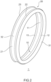
- Fig. 2 is a perspective view of the sealing device 1
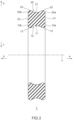
- Fig. 3 is a sectional view in a section along an axis x of the sealing device 1.
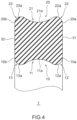
- Fig. 4 is a sectional view enlarging and illustrating one side of the section illustrated in Fig. 3 .
- a side (one side) in an arrow "a" (see Fig. 3 ) direction is defined as a sealed object side
- a side in an arrow "b" see Fig. 3 ) direction is defined as an atmosphere side.
- the object to be sealed is an object to be sealed by the sealing device 1, and a side where the object to be sealed exists, or the side where the object to be sealed is to exist is a sealed object side.
- the atmosphere side is a side opposite to the sealed object side, and is a side that is to be opened to atmosphere.
- the atmosphere side does not have to be opened to atmosphere, and another object to be sealed may exist.
- a side in an arrow "c" (see Fig. 3 ) direction is defined as an inner periphery side
- a side in an arrow "d" (see Fig. 3 ) direction is defined as an outer periphery side.
- the sealing device 1 is a sealing device for sealing an annular space between a shaft that is an attaching target of the sealing device 1 and a shaft hole that is an attaching target of the sealing device 1 in which the shaft is inserted.
- the sealing device 1 is annular around the axis x.
- the sealing device 1 includes an inner peripheral surface 10 that is a surface facing a surface on an inner periphery side (outer peripheral surface of the shaft) of respective surfaces facing each other via the space, of the shaft and the shaft hole, and an outer peripheral surface 20 that is a surface facing a surface on an outer periphery side (inner peripheral surface of the shaft hole) of the respective surfaces facing each other via the space, of the shaft and the shaft hole.
- the inner peripheral surface 10 has an inner peripheral recessed surface 11 that is recessed to the outer periphery side and is a surface annular around the axis x.
- the outer peripheral surface 20 has an outer peripheral recessed surface 21 that is recessed to the inner periphery side and is a surface annular around the axis x.
- the inner peripheral recessed surface 11 of the inner peripheral surface 10 is configured to contact the outer peripheral surface of the shaft.
- the outer peripheral recessed surface 21 of the outer peripheral surface 20 is configured to contact the inner peripheral surface of the shaft hole.
- the attaching targets for which the sealing device 1 is used include a vehicle, construction machinery, industrial machinery, general purpose machines or the like, and in the attaching targets, the sealing device 1 is used to seal between the shaft that relatively moves and the shaft hole which is formed in a housing or the like and in which this shaft is inserted.
- the sealing device 1 is favorably used in a damper, a valve or the like in which a shaft or a shaft hole performs bidirectional rotational movement that rotationally moves in both directions of one rotation direction such as a positive direction or a negative direction and another rotation direction opposite to the one rotation direction.
- the attaching targets to which the sealing device 1 according to the embodiment of the present invention is applied are not limited to the above.
- the sealing device 1 is an annular or substantially annular member with the axis x as a center axis or substantially center axis, and has the inner peripheral surface 10 and the outer peripheral surface 20 that face in opposite directions to each other as described above. Further, the sealing device 1 has a side surface 31 and a side surface 32 that are surfaces that face in opposite directions to each other.
- the side surface 31 is a surface extending between an end on the sealed object side (sealing side end 10a) of the inner peripheral surface 10 and an end on the sealed object side (sealing side end 20a) of the outer peripheral surface 20, and the side surface 32 is a surface extending between an end on the atmosphere side (atmosphere side end 10b) of the inner peripheral surface 10 and an end on the atmosphere side (atmosphere side end 20b) of the outer peripheral surface 20.
- a shape (hereinafter, also simply referred to as a sectional shape) of a section (hereinafter, also simply referred to as a section) along the axis x of the sealing device 1 is a substantial rectangle.
- the inner peripheral surface 10 extends over an extending direction of the sealing device 1, and is a surface having an annular shape or substantially annular shape with the axis x as the center axis or substantially center axis, and a sectional shape ( Figs. 3 and 4 ) of the inner peripheral surface 10 is uniform or substantially uniform over the extending direction (circumferential direction) of the sealing device 1.
- the inner peripheral surface 10 has the aforementioned inner peripheral recessed surface 11, and inner peripheral protruded surfaces 12 and 13 formed on both sides of the inner peripheral recessed surface 11 by the inner peripheral recessed surface 11.
- the inner peripheral recessed surface 11 is formed so that a bottom-most portion 11a of the inner peripheral recessed surface 11 is provided in a center or substantially center in an axis x direction of the inner peripheral recessed surface 11 in a section along the axis x of the sealing device 1.
- the bottom-most portion 11a is a portion that is located in a farthest position from the axis x in a direction orthogonal to the axis x of the inner peripheral recessed surface 11.
- the inner peripheral recessed surface 11 is formed so that an outline in the section of the inner peripheral recessed surface 11 draws an arc-shaped or substantially arc-shaped line, and the bottom-most portion 11a of the inner peripheral recessed surface 11 is formed to be located in the center or substantially center in the axis x direction of the inner peripheral recessed surface 11, in the section.
- the inner peripheral recessed surface 11 is symmetrical or substantially symmetrical about the bottom-most portion 11a.
- the inner peripheral recessed surface 11 is not limited to the one having the shape presenting arc-shaped or substantially arc-shaped shape in the section, but may have other shapes such as a shape presenting an outline drawn by a curved line in the section, a shape presenting an outline drawn by a combination of straight lines in the section, and a shape presenting an outline drawn by a combination of a curved line and a straight line in the section.
- the inner peripheral recessed surface 11 preferably has a shape drawing a smooth line in the section.
- inner peripheral protruded surfaces 12 and 13 that are a pair of surfaces that protrude toward the inner periphery side and are annular around the axis x are formed on both ends of the inner peripheral recessed surface 11 of the inner peripheral surface 10 by the inner peripheral recessed surface 11.
- the inner peripheral protruded surface 12 is located on the sealed object side with respect to the inner peripheral recessed surface 11, and the inner peripheral protruded surface 13 is located on the atmosphere side with respect to the inner peripheral recessed surface 11.
- a protrusion end portion 12a that is a portion located in a position closest to the axis x in the direction orthogonal to the axis x of the inner peripheral protruded surface 12 is located on the inner periphery side in the direction orthogonal to the axis x from the inner peripheral recessed surface 11.
- a protrusion end portion 13a that is a portion located in a position closest to the axis x in the direction orthogonal to the axis x of the inner peripheral protruded surface 13 is located on the inner periphery side in the direction orthogonal to the axis x from the inner peripheral recessed surface 11.
- the protrusion end portion 12a of the inner peripheral protruded surface 12 may be located in a same position in the direction orthogonal to the axis x as a connection portion with the inner peripheral protruded surface 12, of the inner peripheral recessed surface 11, and likewise, in the section, the protrusion end portion 13a of the inner peripheral protruded surface 13 may be located in the same position in the direction orthogonal to the axis x as a connection portion with the inner peripheral protruded surface 13, of the inner peripheral recessed surface 11.
- the protrusion end portion 12a of the inner peripheral protruded surface 12 and the protrusion end portion 13a of the inner peripheral protruded surface 13 may be located in a same position in the direction orthogonal to the axis x or may be located in different positions.
- the inner peripheral protruded surfaces 12 and 13 are provided on both the ends of the inner peripheral surface 10 in the axis x direction, as illustrated in Figs. 3 and 4 , for example.
- the inner peripheral protruded surfaces 12 and 13 do not have to be provided on both the ends of the inner peripheral surface 10 in the axis x direction. In that case, the inner peripheral surface 10 further continues to the sealed object side from the inner peripheral protruded surface 12, and the inner peripheral surface 10 further continues to the atmosphere side from the inner peripheral protruded surface 13.
- the outer peripheral surface 20 extends over an extending direction of the sealing device 1, and is a surface having an annular shape or substantially annular shape with the axis x as the center axis or substantially center axis, and a sectional shape ( Figs. 3 and 4 ) is uniform or substantially uniform over the extending direction (circumferential direction) of the sealing device 1.
- the outer peripheral surface 20 has the aforementioned outer peripheral recessed surface 21, and outer peripheral protruded surfaces 22 and 23 that are formed on both sides of the outer peripheral recessed surface 21 by the outer peripheral recessed surface 21.
- the outer peripheral recessed surface 21 is formed so that a bottom-most portion 21a of the outer peripheral recessed surface 21 is provided in a center or substantially center in an axis x direction of the outer peripheral recessed surface 21 in the section along the axis x of the sealing device 1.
- the bottom-most portion 21a is a portion that is located in a position closest to the axis x in the direction orthogonal to the axis x of the outer peripheral recessed surface 21.
- the outer peripheral recessed surface 21 is formed so that an outline in the section of the outer peripheral recessed surface 21 draws an arc-shaped or substantially arc-shaped line, the bottom-most portion 21a of the outer peripheral recessed surface 21 is formed to be located in the center or substantially center in the axis x direction of the outer peripheral recessed surface 21, in the section.
- the outer peripheral recessed surface 21 is symmetrical or substantially symmetrical about the bottom-most portion 21a.
- the outer peripheral recessed surface 21 is not limited to the one having the shape presenting an arc-shaped or substantially arc-shaped outline in the section, but may have other shapes such as a shape presenting an outline drawn by a curved line in the section, a shape presenting an outline drawn by a combination of straight lines in the section, and a shape presenting an outline drawn by a combination of a curved line and a straight line in the section.
- the outer peripheral recessed surface 21 preferably has a shape drawing a smooth line in the section.
- outer peripheral protruded surfaces 22 and 23 that are a pair of surfaces that protrude toward the outer periphery side and are annular around the axis x are formed on both ends of the outer peripheral recessed surface 21 of the outer peripheral surface 20 by the outer peripheral recessed surface 21.
- the outer peripheral protruded surface 22 is located on the sealed object side with respect to the outer peripheral recessed surface 21, and the outer peripheral protruded surface 23 is located on the atmosphere side with respect to the outer peripheral recessed surface 21.
- a protrusion end portion 22a that is a portion located in a position farthest from the axis x in the direction orthogonal to the axis x of the outer peripheral protruded surface 22 is located on the outer periphery side in the direction orthogonal to the axis x from the outer peripheral recessed surface 21.
- a protrusion end portion 23a that is a portion located in a position farthest from the axis x in the direction orthogonal to the axis x of the outer peripheral protruded surface 23 is located on the outer periphery side in the direction orthogonal to the axis x from the outer peripheral recessed surface 21.
- the protrusion end portion 22a of the outer peripheral protruded surface 22 may be located in a same position in the direction orthogonal to the axis x as a connection portion with the outer peripheral protruded surface 22, of the outer peripheral recessed surface 21, and likewise, in the section, the protrusion end portion 23a of the outer peripheral protruded surface 23 may be located in the same position in the direction orthogonal to the axis x as a connection portion with the outer peripheral protruded surface 23, of the outer peripheral recessed surface 21.
- the protrusion end portion 22a of the outer peripheral protruded surface 22 and the protrusion end portion 23a of the outer peripheral protruded surface 23 may be located in a same position in the direction orthogonal to the axis x or may be located in different positions.
- the outer peripheral protruded surfaces 22 and 23 are provided on both the ends of the outer peripheral surface 20 in the axis x direction, as illustrated in Figs. 3 and 4 , for example.
- the outer peripheral protruded surfaces 22 and 23 do not have to be provided on both the ends of the outer peripheral surface 20 in the axis x direction.
- the outer peripheral surface 20 further continues to the sealed object side from the outer peripheral protruded surface 22, and the outer peripheral surface 20 further continues to the atmosphere side from the outer peripheral protruded surface 23.
- the sealing device 1 is formed so that the inner peripheral recessed surface 11 contacts an outer peripheral surface of the shaft (bottom surface of a groove) as described later in the usage state where the sealing device 1 is attached to the attaching targets. Further, the sealing device 1 is formed so that the outer peripheral recessed surface 21 contacts the inner peripheral surface of the shaft hole as described later in the usage state of the sealing device 1. In other words, in the usage state of the sealing device 1 described later, in a range of the inner peripheral recessed surface 11 and the outer peripheral recessed surface 21, the sealing device 1 is sandwiched between the outer peripheral surface of the shaft and the inner peripheral surface of the shaft hole, and a compression rate in the direction orthogonal to the axis x or the direction substantially orthogonal to the axis x is 0% or more.
- the side surfaces 31 and 32 extend over the extending direction of the sealing device 1, and are surfaces having an annular shape or substantially annular shape with the axis x as the center axis or substantially center axis, and a sectional shape ( Figs. 3 and 4 ) is uniform or substantially uniform over the extending direction (circumferential direction) of the sealing device 1. Further, as illustrated in Figs. 3 and 4 , the side surfaces 31 and 32 extend along a plane orthogonal to the axis x, and extend parallel or substantially parallel to the plane orthogonal to the axis x, for example.
- the inner peripheral protruded surfaces 12 and 13 are symmetrical or substantially symmetrical about the straight line orthogonal to the axis x in the section, and the outer peripheral protruded surfaces 22 and 23 are symmetrical or substantially symmetrical about the straight line orthogonal to the axis x in the section. Further, the inner peripheral protruded surface 12 and the outer peripheral protruded surface 22 are symmetrical or substantially symmetrical about a straight line parallel to the axis x in the section. Further, the inner peripheral protruded surface 13 and the outer peripheral protruded surface 23 are symmetrical or substantially symmetrical about a straight line parallel to the axis x in the section.
- the inner peripheral recessed surface 11 and the outer peripheral recessed surface 21 are symmetrical or substantially symmetrical about a straight line parallel to the axis x in the section.
- the inner peripheral protruded surfaces 12 and 13 do not have to be symmetrical about the straight line orthogonal to the axis x in the section.
- the outer peripheral protruded surfaces 22 and 23 do not have to be symmetrical about the straight line orthogonal to the axis x in the section.
- the inner peripheral protruded surface 12 and the outer peripheral protruded surface 22 do not have to be symmetrical about the straight line parallel to the axis x in the section.
- the inner peripheral protruded surface 13 and the outer peripheral protruded surface 23 do not have to be symmetrical about the straight line parallel to the axis x in the section. Further, the inner peripheral recessed surface 11 and the outer peripheral recessed surface 21 do not have to be symmetrical about the straight line parallel to the axis x in the section.
- the sealing device 1 is a rubber-like elastic body, and as a rubber material of the sealing device 1, for example, fluororubber (FKM), ethylene propylene rubber (EPDM), hydrogenated nitrile rubber (H-NBR), nitrile rubber (NBR), acrylic rubber (ACM), ethylene acrylic rubber (AEM), vinyl methyl silicone rubber (VMQ), fluorosilicone rubber (FVMQ) and the like are listed.
- FKM fluororubber
- EPDM ethylene propylene rubber
- H-NBR hydrogenated nitrile rubber
- NBR nitrile rubber
- ACM acrylic rubber
- AEM ethylene acrylic rubber
- VMQ vinyl methyl silicone rubber
- FVMQ fluorosilicone rubber
- the sealing device 1 is used to seal an annular space between a shaft and a shaft hole in which the shaft is inserted, as described above.
- the sealing device 1 is designed to seal an annular space between a shaft 50 and a shaft hole 61 in which the shaft 50 is inserted, as illustrated in Fig. 5 , for example.
- the shaft hole 61 is a through-hole formed in a housing 60, and the housing 60 is a cylindrical or circular-cylindrical member, for example.
- an annular groove 51 is formed around an axis of the shaft 50, and the sealing device 1 is accommodated in the groove 51 to be brought into the usage state.
- Fig. 5 is a sectional view illustrating the sealing device 1 in the usage state where the sealing device 1 is attached to the shaft 50 and the shaft hole 61 of the housing 60 that are the attaching targets.
- the groove 51 is recessed from an outer peripheral surface 50a of the shaft 50, and opens to a space between the shaft 50 and the shaft hole 61 as illustrated in Fig. 5 . Further, as illustrated in Fig. 5 , the groove 51 has a pair of side surfaces 51a and 51b that face each other, and has a bottom surface 51c that extends between the side surfaces 51a and 51b.
- the side surface 51a is a side surface located on the sealed object side (arrow "a" direction side), and the side surface 51b is a side surface located on the atmosphere side (arrow "b" direction side).
- the groove 51 may be formed on an inner peripheral surface 61a of the shaft hole 61 of the housing 60 instead of the shaft 50. Further, the groove may be formed in the shaft 50 and the housing 60.
- the attaching target is, for example, a damper, a valve such as an EGR valve or the like, and the shaft 50 and the housing 60 rotationally move bidirectionally relative to each other.
- the shaft 50 may perform bidirectional rotational movement and the housing 60 may be fixed, the shaft 50 may be fixed and the housing 60 may perform bidirectional rotational movement, or the shaft 50 and the housing 60 may mutually perform bidirectional rotational movement.
- the sealing device 1 in the usage state where the sealing device 1 is attached to the shaft 50 and the housing 60 that are the attaching targets is compressed between the bottom surface 51c of the groove 51 and the inner peripheral surface 61a of the shaft hole 61 of the housing 60, and closes a gap between the shaft 50 and the shaft hole 61 of the housing 60.
- a space between the shaft 50 and the shaft hole 61 is sealed, and a space on the sealed object side is sealed.
- the space on the atmosphere side is also sealed, and the space on the atmosphere side may be sealed by the sealing device 1.
- the sealing device 1 in the usage state, the sealing device 1 is compressed between the bottom surface 51c of the groove 51 and the inner peripheral surface 61a of the shaft hole 61 of the housing 60. At this time, the sealing device 1 also deforms in the axis x direction to extend in the axis x direction, and as described above, the entire inner peripheral recessed surface 11 of the sealing device 1 contacts the bottom surface 51c of the groove 51, whereas the entire outer peripheral recessed surface 21 of the sealing device 1 contacts the inner peripheral surface 61a of the shaft hole 61.
- the compression rate of the sealing device 1 in the direction orthogonal to the axis x or the direction substantially orthogonal to the axis x is 0% or more.
- the inner peripheral protruded surfaces 12 and 13 of the inner peripheral surface 10 of the sealing device 1 are pressed against the bottom surface 51c of the groove 51 of the shaft 50, and the outer peripheral protruded surfaces 22 and 23 of the outer peripheral surface 20 of the sealing device 1 are pressed against the inner peripheral surface 61a of the shaft hole 61.
- the entire inner peripheral recessed surface 11 contacts the bottom surface 51c of the groove 51 in addition to the inner peripheral protruded surfaces 12 and 13 of the inner peripheral surface 10. Therefore, a width in the axis x direction of a region that contacts the bottom surface 51c of the groove 51, of the sealing device 1 in the usage state is larger than a width in the axis x direction between the inner peripheral protruded surfaces 12 and 13 of the sealing device 1 in a free state with no load illustrated in Figs. 1 to 4 . Therefore, the sealing device 1 can increase a contact region (seal surface) to the bottom surface 51c of the groove 51 of the sealing device 1 in the usage state.
- the sealing device 1 in the usage state the entire outer peripheral recessed surface 21 contacts the inner peripheral surface 61a of the shaft hole 61, in addition to the outer peripheral protruded surfaces 22 and 23 of the outer peripheral surface 20. Therefore, a width in the axis x direction in a region that contacts the inner peripheral surface 61a of the shaft hole 61 of the sealing device 1 in the usage state is larger than a width in the axis x direction between the outer peripheral protruded surfaces 22 and 23 of the sealing device 1 in the free state with no load illustrated in Figs. 1 to 4 . Therefore, the sealing device 1 can increase a contact region to the inner peripheral surface 61a of the shaft hole 61 of the sealing device 1 in the usage state.
- the sealing device 1 can increase the contact region to the bottom surface 51c of the groove 51, of the sealing device 1 in the usage state, can increase the contact region to the inner peripheral surface 61a of the shaft hole 61, of the sealing device 1 in the usage state, and can improve sealing performance of the sealing device 1.
- the sealed object may enter the contact surface on the inner peripheral surface 10 side of the sealing device 1 or the contact surface on the outer peripheral surface 20 side. In this case, it is also difficult for the sealed object that has entered the contact surface of the sealing device 1 to reach the atmosphere side on the opposite side, since the contact region of the sealing device 1 in the usage state is large as described above. In this way, the sealing device 1 can suppress oozing and leakage of the sealed object due to bidirectional rotational movement of the attaching targets.
- the inner peripheral protruded surfaces 12 and 13 of the inner peripheral surface 10 are high compression portions, and surface pressure of the contact surface of the sealing device 1 shows distinction in the inner peripheral protruded surfaces 12 and 13.
- the outer peripheral protruded surfaces 22 and 23 of the outer peripheral surface 20 are high compression portions, and the surface pressure of the contact surface of the sealing device 1 shows distinction in the outer peripheral protruded surfaces 22 and 23. Therefore, in the usage state, peak surface pressure can be generated on the sealed object side and the atmosphere side of the contact surface of the sealing device 1, a surface pressure gradient can be increased, and entry of the sealed object to inside of the contact surface can be made difficult. Thereby, sealing performance of the sealing device 1 can be improved.
- the compression rate of the inner peripheral recessed surface 11 of the sealing device 1 in the usage state is 0% or more, and the compression rate of the outer peripheral recessed surface 21 of the sealing device 1 in the usage state is 0% or more. Therefore, a rotational reaction force that occurs to the contact surface can be reduced, while the contact surface is increased as described above, driving torque of the shaft 50 or the housing 60 can be reduced, and wear of the sealing device 1, the bottom surface 51c of the groove 51, or the inner peripheral surface 61a of the shaft hole 61 can be reduced.
- the sealing device 1 has the inner peripheral recessed surface 11 and the outer peripheral recessed surface 21 on the contact surface, the contact surface pressure in the usage state decreases from the sealed object side toward the atmosphere side, and the surface pressure increases from the bottom-most portion 11a of the inner peripheral recessed surface 11 and the bottom-most portion 21a of the outer peripheral recessed surface 21. Therefore, for example, at the time of switching of the direction of rotation of the shaft 50 or the housing 60, or when the attaching targets stop moving, the sealed object that enters toward the atmosphere side from the sealed object side can be returned to the sealed object side. Thereby, oozing and leakage of the sealed object can be suppressed. When another object to be sealed is sealed in the space on the atmosphere side, oozing and leakage of the other sealed object can also be suppressed similarly.
- the sealing device 1 can exhibit an action of returning the sealed object described above similarly on the sealed object side and the atmosphere side of the inner peripheral recessed surface 11 and the outer peripheral recessed surface 21. Therefore, the sealing device 1 can be favorably used for an attaching target where another object to be sealed is also sealed in the space on the atmosphere side in addition to the space on the sealed object side.
- the sealing device 1 according to the first embodiment of the present invention, it is possible to improve sealing performance concerning oozing and leakage based on bidirectional rotational movement of the shaft 50 or the housing 60, of the sealing device 1.
- Fig. 6 is a sectional view in a section along an axis x of the sealing device 2 according to the second embodiment of the present invention
- Fig. 7 is a sectional view enlarging and illustrating one side of a section of the sealing device 2.
- the sealing device 2 according to the second embodiment of the present invention differs from the sealing device 1 according to the first embodiment of the present invention described above in the forms of the inner peripheral recessed surface and the outer peripheral recessed surface and has an inner peripheral recessed surface 15 and an outer peripheral recessed surface 25 that are different from the inner peripheral recessed surface 11 and the outer peripheral recessed surface 21 of the aforementioned sealing device 1.
- the components having the same configurations as or similar functions to the aforementioned sealing device 1 are assigned with the same reference signs to omit explanation thereof, and different components are be described.
- the inner peripheral recessed surface 15 of an inner peripheral surface 10 of the sealing device 2 is recessed to an outer periphery side similarly to the inner peripheral recessed surface 11 of the inner peripheral surface 10 of the sealing device 1, and has a bottom-most portion 15a corresponding to the bottom-most portion 11a of the inner peripheral recessed surface 11.
- the bottom-most portion 15a is a portion located in a position farthest from the axis x in a direction orthogonal to the axis x, of the inner peripheral recessed surface 15, in a section.
- a sectional shape of the inner peripheral recessed surface 15 is different from the sectional shape of the inner peripheral recessed surface 11, and the bottom-most portion 15a is not located in a center or substantially center in the axis x direction.
- the sectional shape of the inner peripheral recessed surface 15 is not symmetrical or substantially symmetrical about the bottom-most portion 15a.
- the bottom-most portion 15a is provided on the sealed object side in the axis x direction of the inner peripheral recessed surface 15.
- the bottom-most portion 15a is provided on the sealed object side from the center in the axis x direction of the inner peripheral recessed surface 15.
- the inner peripheral recessed surface 15 has a shape such as a shape that presents an outline drawn by a curved line in the section, a shape that presents an outline drawn by a combination of straight lines in the section, or a shape that presents an outline drawn by a combination of a curved line and a straight line in the section.
- the inner peripheral recessed surface 15 preferably has a shape that draws a smooth line in the section.
- the bottom-most portion 15a of the inner peripheral recessed surface 15 is provided on the sealed object side, and a width in the axis x direction is larger in a portion on the atmosphere side from the bottom-most portion 15a of the inner peripheral recessed surface 15 than a portion on the sealed object side from the bottom-most portion 15a of the inner peripheral recessed surface 15.
- the outer peripheral recessed surface 25 of an outer peripheral surface 20 of the sealing device 2 is recessed to an inner periphery side similarly to the outer peripheral recessed surface 21 of the outer peripheral surface 20 of the sealing device 1, and has a bottom-most portion 25a corresponding to the bottom-most portion 21a of the outer peripheral recessed surface 21.
- the bottom-most portion 25a is a portion located in a position closest to the axis x in a direction orthogonal to the axis x, of the outer peripheral recessed surface 25, in the section.
- a sectional shape of the outer peripheral recessed surface 25 is different from the sectional shape of the outer peripheral recessed surface 21, and the bottom-most portion 25a is not located in a center or substantially center in the axis x direction.
- the sectional shape of the outer peripheral recessed surface 25 is not symmetrical or substantially symmetrical about the bottom-most portion 25a.
- the bottom-most portion 25a is provided on the sealed object side in the axis x direction of the outer peripheral recessed surface 25.
- the bottom-most portion 25a is provided on the sealed object side from the center in the axis x direction of the outer peripheral recessed surface 25.
- the outer peripheral recessed surface 25 has a shape such as a shape that presents an outline drawn by a curved line in the section, a shape that presents an outline drawn by a combination of straight lines in the section, or a shape that presents an outline drawn by a combination of a curved line and a straight line in the section.
- the outer peripheral recessed surface 25 preferably has a shape that draws a smooth line in the section.
- the bottom-most portion 25a of the outer peripheral recessed surface 25 is provided on the sealed object side, and a width in the axis x direction is larger in a portion on the atmosphere side from the bottom-most portion 25a of the outer peripheral recessed surface 25 than a portion on the sealed object side from the bottom-most portion 25a of the outer peripheral recessed surface 25.
- the sealing device 2 is formed so that the inner peripheral recessed surface 15 contacts the bottom surface 51c of the groove 51 of the shaft 50 in the usage state where the sealing device 2 is attached to the attaching targets, similarly to the sealing device 1. Further, the sealing device 2 is formed so that the outer peripheral recessed surface 25 contacts the inner peripheral surface 61a of the shaft hole 61 in the usage state of the sealing device 2 similarly to the sealing device 1.
- the sealing device 2 in a range of the inner peripheral recessed surface 15 and the outer peripheral recessed surface 25, the sealing device 2 is sandwiched between the bottom surface 51c of the groove 51 of the shaft 50 and the inner peripheral surface 61a of the shaft hole 61, and a compression rate in the direction orthogonal to the axis x or the direction substantially orthogonal to the axis x is 0% or more.
- the inner peripheral recessed surface 15 and the outer peripheral recessed surface 25 are symmetrical or substantially symmetrical about a straight line parallel to the axis x. In the section of the sealing device 2, the inner peripheral recessed surface 15 and the outer peripheral recessed surface 25 do not have to be symmetrical about the straight line parallel to the axis x.
- the sealing device 2 is used to seal an annular space between a shaft and a shaft hole in which the shaft is inserted, similarly to the aforementioned sealing device 1.
- the sealing device 2 is accommodated in the groove 51 of the shaft 50 to seal an annular space between the shaft 50 and the shaft hole 61 in which the shaft 50 is inserted, as illustrated in Fig. 8 , for example.
- Fig. 8 is a sectional view illustrating the sealing device 2 in the usage state where the sealing device 2 is attached to the shaft 50 and the shaft hole 61 of the housing 60 that are attaching targets.
- the sealing device 2 operates similarly to the aforementioned sealing device 1 and exhibits similar effects.
- the bottom-most portion 15a is provided on the sealed object side from the center in the axis x direction of the inner peripheral recessed surface 15, and a width in the axis x direction of a portion on the atmosphere side from the bottom-most portion 15a of the inner peripheral recessed surface 15 is larger than a width in the axis x direction of a portion on the sealed object side from the bottom-most portion 15a of the inner peripheral recessed surface 15.
- the action of returning the sealed object that has entered to the sealed object side works in a wide range, and the action of returning the sealed object to the sealed object side can be improved since the width in the axis x direction of the portion on the atmosphere side from the bottom-most portion 15a of the inner peripheral recessed surface 15 is large.
- the bottom-most portion 25a is provided on the sealed object side from the center in the axis x direction of the outer peripheral recessed surface 25, and a width in the axis x direction of a portion on the atmosphere side from the bottom-most portion 25a of the outer peripheral recessed surface 25 is larger than a width in the axis x direction of a portion on the sealed object side from the bottom-most portion 25a of the outer peripheral recessed surface 25.
- the action of returning the sealed object that has entered to the sealed object side works in a wide range, and the action of returning the sealed object to the sealed object side can be improved, since the width in the axis x direction of the portion on the atmosphere side from the bottom-most portion 25a of the outer peripheral recessed surface 25 is large.
- the sealing device 2 the action of returning the sealed object to the sealed object side on the inner peripheral recessed surface 15 and the outer peripheral recessed surface 25 can be improved, and sealing performance can be more improved. Therefore, the sealing device 2 can be favorably used for the attaching target in which another object to be sealed is not sealed on the atmosphere side.
- the sealing device 2 according to the second embodiment of the present invention, it is possible to improve sealing performance concerning oozing and leakage of the sealed object based on the bidirectional rotational movement of the shaft 50 or the housing 60, of the sealing device 2.
- the present invention is not limited to the sealing devices 1 and 2 according to the embodiments of the present invention described above, and includes all aspects included in the idea and the claims of the present invention.
- the respective components may be selectively combined appropriately to exhibit at least part of the aforementioned object and effects.
- the shapes, materials, arrangements, sizes and the like of the respective components in the above-described embodiments can be changed as appropriate according to a specific usage aspect of the present invention.
Landscapes
- Engineering & Computer Science (AREA)
- General Engineering & Computer Science (AREA)
- Mechanical Engineering (AREA)
- Sealing Devices (AREA)
- Gasket Seals (AREA)
Abstract
Description
- The present invention relates to a sealing device.
- Sealing devices have been conventionally used to seal the space between members capable of relative movement such as rotational movement. Some of such sealing devices close a gap between the shaft and the hole in which the shaft is inserted or the cylindrical surface, and form two separated spaces, for example. Such sealing devices are required to reduce resistance to rotation (rotational resistance) and improve sealing performance, and various proposals have been made therefor (for example, see Patent Literature 1).
- Patent Literature 1:
Japanese Patent Application Publication No. 2018-173089 - As described above, some of the conventional sealing devices have a configuration to reduce rotational resistance and improve sealing performance, and in some cases, it is required to improve the sealing performance regarding oozing and leakage of the sealed object such as a working fluid due to the rotational movement in both directions of the attaching target of the sealing deice such as a shaft.
- It is an object of the present invention to provide a sealing device that can improve sealing performance regarding oozing and leakage of a sealed object based on bidirectional rotational movement of an attaching target of the sealing device.
- In order to attain the above-described object, a sealing device according to the present invention is a sealing device that is annular around an axis to seal an annular space between a shaft and a shaft hole in which the shaft is inserted, and is characterized by including an inner peripheral surface that is a surface facing a surface on an inner periphery side of respective surfaces facing each other via the space, of the shaft and the shaft hole, and an outer peripheral surface that is a surface facing a surface on an outer periphery side of the respective surfaces facing each other via the space, of the shaft and the shaft hole, and characterized in that the inner peripheral surface has an inner peripheral recessed surface that is a surface recessed to the outer periphery side and annular around the axis, the outer peripheral surface has an outer peripheral recessed surface that is a surface recessed to the inner periphery side and annular around the axis, the inner peripheral recessed surface of the inner peripheral surface contacts a surface on the inner periphery side of respective surfaces facing each other via the space, of the shaft or the shaft hole, and the outer peripheral recessed surface of the outer peripheral surface contacts a surface on the outer periphery side of the respective surfaces facing via the space, of the shaft or the shaft hole.
- In the sealing device according one aspect of the present invention, in a section along the axis of the sealing device, a portion located in a position farthest from the axis in a direction orthogonal to the axis, of the inner peripheral recessed surface is provided in a center or substantially center in the axis direction, of the inner peripheral recessed surface, and in the section along the axis of the sealing device, a portion located in a position closest to the axis in the direction orthogonal to the axis, of the outer peripheral recessed surface is provided in a center or substantially center in the axis direction, of the outer peripheral recessed surface.
- In the sealing device according to one aspect of the present invention, in a section along the axis of the sealing device, a portion located in a position farthest from the axis in a direction orthogonal to the axis, of the inner peripheral recessed surface is provided on one side in the axis direction, of the inner peripheral recessed surface, and in the section along the axis of the sealing device, a portion located in a position closest to the axis in the direction orthogonal to the axis, of the outer peripheral recessed surface is provided on the one side in the axis direction, of the outer peripheral recessed surface, and the one side in the axis direction is a side to be a side of a sealed object.
- In the sealing device according to one aspect of the present invention, by the inner peripheral recessed surface, inner peripheral protruded surfaces that are a pair of surfaces that protrude toward the inner periphery side and are annular around the axis are formed on both ends of the inner peripheral surface in the axis direction, and by the outer peripheral recessed surface, outer peripheral protruded surfaces that are a pair of surfaces that protrude toward the outer periphery side and are annular around the axis are formed on both ends of the outer peripheral surface in the axis direction.
- In the sealing device according to one aspect of the present invention, the shaft or the shaft hole performs bidirectional rotational movement.
- According to the sealing device of the present invention, sealing performance concerning oozing and leakage of a sealed object based on bidirectional rotational movement of an attaching target of the sealing device can be improved.
-
- [
Fig. 1 ] A plan view of a sealing device according to an embodiment of the present invention. - [
Fig. 2 ] A perspective view of the sealing device illustrated inFig. 1 . - [
Fig. 3 ] A sectional view in a section along an axis of the sealing device illustrated inFig. 1 . - [
Fig. 4 ] A sectional view enlarging and illustrating one side of the section illustrated inFig. 3 . - [
Fig. 5 ] A sectional view illustrating a sealing device in a usage state where the sealing device illustrated inFig. 1 is attached to a shaft and a shaft hole of a housing that are attaching targets. - [
Fig. 6 ] A sectional view in a section along an axis of a sealing device according to a second embodiment of the present invention. - [
Fig. 7 ] A sectional view enlarging and illustrating one side of the section illustrated inFig. 6 . - [
Fig. 8 ] A sectional view illustrating the sealing device in a usage state where the sealing device illustrated inFig. 6 is attached to a shaft and a shaft hole of a housing that are attaching targets. - Hereinafter, embodiments of the present invention will be described with reference to the drawings.
-
Fig. 1 is a plan view of asealing device 1 according to a first embodiment of the present invention,Fig. 2 is a perspective view of thesealing device 1, andFig. 3 is a sectional view in a section along an axis x of thesealing device 1.Fig. 4 is a sectional view enlarging and illustrating one side of the section illustrated inFig. 3 . Hereinafter, for convenience of explanation, a side (one side) in an arrow "a" (seeFig. 3 ) direction is defined as a sealed object side, and a side in an arrow "b" (seeFig. 3 ) direction is defined as an atmosphere side. The object to be sealed is an object to be sealed by thesealing device 1, and a side where the object to be sealed exists, or the side where the object to be sealed is to exist is a sealed object side. The atmosphere side is a side opposite to the sealed object side, and is a side that is to be opened to atmosphere. The atmosphere side does not have to be opened to atmosphere, and another object to be sealed may exist. Further, a side in an arrow "c" (seeFig. 3 ) direction is defined as an inner periphery side, and a side in an arrow "d" (seeFig. 3 ) direction is defined as an outer periphery side. - The
sealing device 1 according to the present embodiment is a sealing device for sealing an annular space between a shaft that is an attaching target of thesealing device 1 and a shaft hole that is an attaching target of thesealing device 1 in which the shaft is inserted. Thesealing device 1 is annular around the axis x. Thesealing device 1 includes an innerperipheral surface 10 that is a surface facing a surface on an inner periphery side (outer peripheral surface of the shaft) of respective surfaces facing each other via the space, of the shaft and the shaft hole, and an outerperipheral surface 20 that is a surface facing a surface on an outer periphery side (inner peripheral surface of the shaft hole) of the respective surfaces facing each other via the space, of the shaft and the shaft hole. The innerperipheral surface 10 has an inner peripheralrecessed surface 11 that is recessed to the outer periphery side and is a surface annular around the axis x. The outerperipheral surface 20 has an outer peripheralrecessed surface 21 that is recessed to the inner periphery side and is a surface annular around the axis x. The inner peripheralrecessed surface 11 of the innerperipheral surface 10 is configured to contact the outer peripheral surface of the shaft. The outer peripheralrecessed surface 21 of the outerperipheral surface 20 is configured to contact the inner peripheral surface of the shaft hole. Hereinafter, thesealing device 1 will be specifically described. - The attaching targets for which the
sealing device 1 is used include a vehicle, construction machinery, industrial machinery, general purpose machines or the like, and in the attaching targets, thesealing device 1 is used to seal between the shaft that relatively moves and the shaft hole which is formed in a housing or the like and in which this shaft is inserted. Thesealing device 1 is favorably used in a damper, a valve or the like in which a shaft or a shaft hole performs bidirectional rotational movement that rotationally moves in both directions of one rotation direction such as a positive direction or a negative direction and another rotation direction opposite to the one rotation direction. Note that the attaching targets to which thesealing device 1 according to the embodiment of the present invention is applied are not limited to the above. - As illustrated in
Figs. 1 and2 , thesealing device 1 is an annular or substantially annular member with the axis x as a center axis or substantially center axis, and has the innerperipheral surface 10 and the outerperipheral surface 20 that face in opposite directions to each other as described above. Further, thesealing device 1 has aside surface 31 and aside surface 32 that are surfaces that face in opposite directions to each other. Theside surface 31 is a surface extending between an end on the sealed object side (sealing side end 10a) of the innerperipheral surface 10 and an end on the sealed object side (sealing side end 20a) of the outerperipheral surface 20, and theside surface 32 is a surface extending between an end on the atmosphere side (atmosphere side end 10b) of the innerperipheral surface 10 and an end on the atmosphere side (atmosphere side end 20b) of the outerperipheral surface 20. As illustrated inFigs. 3 and4 , a shape (hereinafter, also simply referred to as a sectional shape) of a section (hereinafter, also simply referred to as a section) along the axis x of thesealing device 1 is a substantial rectangle. - As illustrated in
Figs. 1 and2 , the innerperipheral surface 10 extends over an extending direction of thesealing device 1, and is a surface having an annular shape or substantially annular shape with the axis x as the center axis or substantially center axis, and a sectional shape (Figs. 3 and4 ) of the innerperipheral surface 10 is uniform or substantially uniform over the extending direction (circumferential direction) of thesealing device 1. Further, the innerperipheral surface 10 has the aforementioned inner peripheralrecessed surface 11, and inner peripheralprotruded surfaces recessed surface 11 by the inner peripheralrecessed surface 11. - As illustrated in
Figs. 3 and4 , the inner peripheralrecessed surface 11 is formed so that abottom-most portion 11a of the inner peripheralrecessed surface 11 is provided in a center or substantially center in an axis x direction of the inner peripheralrecessed surface 11 in a section along the axis x of thesealing device 1. In the section, thebottom-most portion 11a is a portion that is located in a farthest position from the axis x in a direction orthogonal to the axis x of the inner peripheralrecessed surface 11. Specifically, the inner peripheralrecessed surface 11 is formed so that an outline in the section of the inner peripheralrecessed surface 11 draws an arc-shaped or substantially arc-shaped line, and thebottom-most portion 11a of the inner peripheralrecessed surface 11 is formed to be located in the center or substantially center in the axis x direction of the inner peripheralrecessed surface 11, in the section. In other words, in the section, the inner peripheralrecessed surface 11 is symmetrical or substantially symmetrical about thebottom-most portion 11a. The inner peripheralrecessed surface 11 is not limited to the one having the shape presenting arc-shaped or substantially arc-shaped shape in the section, but may have other shapes such as a shape presenting an outline drawn by a curved line in the section, a shape presenting an outline drawn by a combination of straight lines in the section, and a shape presenting an outline drawn by a combination of a curved line and a straight line in the section. However, the inner peripheralrecessed surface 11 preferably has a shape drawing a smooth line in the section. - As illustrated in
Figs. 3 and4 , inner peripheralprotruded surfaces recessed surface 11 of the innerperipheral surface 10 by the inner peripheralrecessed surface 11. The inner peripheral protrudedsurface 12 is located on the sealed object side with respect to the inner peripheralrecessed surface 11, and the inner peripheralprotruded surface 13 is located on the atmosphere side with respect to the inner peripheralrecessed surface 11. In the section, aprotrusion end portion 12a that is a portion located in a position closest to the axis x in the direction orthogonal to the axis x of the inner peripheralprotruded surface 12 is located on the inner periphery side in the direction orthogonal to the axis x from the inner peripheralrecessed surface 11. Likewise, in the section, aprotrusion end portion 13a that is a portion located in a position closest to the axis x in the direction orthogonal to the axis x of the inner peripheralprotruded surface 13 is located on the inner periphery side in the direction orthogonal to the axis x from the inner peripheralrecessed surface 11. Note that in the section, theprotrusion end portion 12a of the inner peripheralprotruded surface 12 may be located in a same position in the direction orthogonal to the axis x as a connection portion with the inner peripheralprotruded surface 12, of the inner peripheralrecessed surface 11, and likewise, in the section, theprotrusion end portion 13a of the inner peripheralprotruded surface 13 may be located in the same position in the direction orthogonal to the axis x as a connection portion with the inner peripheralprotruded surface 13, of the inner peripheralrecessed surface 11. In the section, theprotrusion end portion 12a of the inner peripheral protrudedsurface 12 and theprotrusion end portion 13a of the inner peripheral protrudedsurface 13 may be located in a same position in the direction orthogonal to the axis x or may be located in different positions. - The inner peripheral protruded
surfaces peripheral surface 10 in the axis x direction, as illustrated inFigs. 3 and4 , for example. The inner peripheral protrudedsurfaces peripheral surface 10 in the axis x direction. In that case, the innerperipheral surface 10 further continues to the sealed object side from the inner peripheral protrudedsurface 12, and the innerperipheral surface 10 further continues to the atmosphere side from the inner peripheral protrudedsurface 13. - As illustrated in
Figs. 1 and2 , the outerperipheral surface 20 extends over an extending direction of thesealing device 1, and is a surface having an annular shape or substantially annular shape with the axis x as the center axis or substantially center axis, and a sectional shape (Figs. 3 and4 ) is uniform or substantially uniform over the extending direction (circumferential direction) of thesealing device 1. Further, the outerperipheral surface 20 has the aforementioned outer peripheral recessedsurface 21, and outer peripheral protrudedsurfaces surface 21 by the outer peripheral recessedsurface 21. - As illustrated in
Figs. 3 and4 , the outer peripheral recessedsurface 21 is formed so that abottom-most portion 21a of the outer peripheral recessedsurface 21 is provided in a center or substantially center in an axis x direction of the outer peripheral recessedsurface 21 in the section along the axis x of thesealing device 1. In the section, thebottom-most portion 21a is a portion that is located in a position closest to the axis x in the direction orthogonal to the axis x of the outer peripheral recessedsurface 21. Specifically, the outer peripheral recessedsurface 21 is formed so that an outline in the section of the outer peripheral recessedsurface 21 draws an arc-shaped or substantially arc-shaped line, thebottom-most portion 21a of the outer peripheral recessedsurface 21 is formed to be located in the center or substantially center in the axis x direction of the outer peripheral recessedsurface 21, in the section. In other words, in the section, the outer peripheral recessedsurface 21 is symmetrical or substantially symmetrical about thebottom-most portion 21a. The outer peripheral recessedsurface 21 is not limited to the one having the shape presenting an arc-shaped or substantially arc-shaped outline in the section, but may have other shapes such as a shape presenting an outline drawn by a curved line in the section, a shape presenting an outline drawn by a combination of straight lines in the section, and a shape presenting an outline drawn by a combination of a curved line and a straight line in the section. However, the outer peripheral recessedsurface 21 preferably has a shape drawing a smooth line in the section. - As illustrated in
Figs. 3 and4 , outer peripheral protrudedsurfaces surface 21 of the outerperipheral surface 20 by the outer peripheral recessedsurface 21. The outer peripheral protrudedsurface 22 is located on the sealed object side with respect to the outer peripheral recessedsurface 21, and the outer peripheral protrudedsurface 23 is located on the atmosphere side with respect to the outer peripheral recessedsurface 21. In the section, aprotrusion end portion 22a that is a portion located in a position farthest from the axis x in the direction orthogonal to the axis x of the outer peripheral protrudedsurface 22 is located on the outer periphery side in the direction orthogonal to the axis x from the outer peripheral recessedsurface 21. Likewise, in the section, aprotrusion end portion 23a that is a portion located in a position farthest from the axis x in the direction orthogonal to the axis x of the outer peripheral protrudedsurface 23 is located on the outer periphery side in the direction orthogonal to the axis x from the outer peripheral recessedsurface 21. Note that in the section, theprotrusion end portion 22a of the outer peripheral protrudedsurface 22 may be located in a same position in the direction orthogonal to the axis x as a connection portion with the outer peripheral protrudedsurface 22, of the outer peripheral recessedsurface 21, and likewise, in the section, theprotrusion end portion 23a of the outer peripheral protrudedsurface 23 may be located in the same position in the direction orthogonal to the axis x as a connection portion with the outer peripheral protrudedsurface 23, of the outer peripheral recessedsurface 21. In the section, theprotrusion end portion 22a of the outer peripheral protrudedsurface 22 and theprotrusion end portion 23a of the outer peripheral protrudedsurface 23 may be located in a same position in the direction orthogonal to the axis x or may be located in different positions. - The outer peripheral protruded
surfaces peripheral surface 20 in the axis x direction, as illustrated inFigs. 3 and4 , for example. The outer peripheral protrudedsurfaces peripheral surface 20 in the axis x direction. In this case, the outerperipheral surface 20 further continues to the sealed object side from the outer peripheral protrudedsurface 22, and the outerperipheral surface 20 further continues to the atmosphere side from the outer peripheral protrudedsurface 23. - The
sealing device 1 is formed so that the inner peripheral recessedsurface 11 contacts an outer peripheral surface of the shaft (bottom surface of a groove) as described later in the usage state where thesealing device 1 is attached to the attaching targets. Further, thesealing device 1 is formed so that the outer peripheral recessedsurface 21 contacts the inner peripheral surface of the shaft hole as described later in the usage state of thesealing device 1. In other words, in the usage state of thesealing device 1 described later, in a range of the inner peripheral recessedsurface 11 and the outer peripheral recessedsurface 21, thesealing device 1 is sandwiched between the outer peripheral surface of the shaft and the inner peripheral surface of the shaft hole, and a compression rate in the direction orthogonal to the axis x or the direction substantially orthogonal to the axis x is 0% or more. - As illustrated in
Figs. 1 and2 , the side surfaces 31 and 32 extend over the extending direction of thesealing device 1, and are surfaces having an annular shape or substantially annular shape with the axis x as the center axis or substantially center axis, and a sectional shape (Figs. 3 and4 ) is uniform or substantially uniform over the extending direction (circumferential direction) of thesealing device 1. Further, as illustrated inFigs. 3 and4 , the side surfaces 31 and 32 extend along a plane orthogonal to the axis x, and extend parallel or substantially parallel to the plane orthogonal to the axis x, for example. - The inner peripheral protruded
surfaces surfaces surface 12 and the outer peripheral protrudedsurface 22 are symmetrical or substantially symmetrical about a straight line parallel to the axis x in the section. Further, the inner peripheral protrudedsurface 13 and the outer peripheral protrudedsurface 23 are symmetrical or substantially symmetrical about a straight line parallel to the axis x in the section. Further, the inner peripheral recessedsurface 11 and the outer peripheral recessedsurface 21 are symmetrical or substantially symmetrical about a straight line parallel to the axis x in the section. The inner peripheral protrudedsurfaces surfaces surface 12 and the outer peripheral protrudedsurface 22 do not have to be symmetrical about the straight line parallel to the axis x in the section. Further, the inner peripheral protrudedsurface 13 and the outer peripheral protrudedsurface 23 do not have to be symmetrical about the straight line parallel to the axis x in the section. Further, the inner peripheral recessedsurface 11 and the outer peripheral recessedsurface 21 do not have to be symmetrical about the straight line parallel to the axis x in the section. - The
sealing device 1 is a rubber-like elastic body, and as a rubber material of thesealing device 1, for example, fluororubber (FKM), ethylene propylene rubber (EPDM), hydrogenated nitrile rubber (H-NBR), nitrile rubber (NBR), acrylic rubber (ACM), ethylene acrylic rubber (AEM), vinyl methyl silicone rubber (VMQ), fluorosilicone rubber (FVMQ) and the like are listed. Thesealing device 1 is integrally made from the rubber-like elastic body. - Thereafter, an operation of the
sealing device 1 having the aforementioned configuration will be described. - The
sealing device 1 is used to seal an annular space between a shaft and a shaft hole in which the shaft is inserted, as described above. Thesealing device 1 is designed to seal an annular space between ashaft 50 and ashaft hole 61 in which theshaft 50 is inserted, as illustrated inFig. 5 , for example. Theshaft hole 61 is a through-hole formed in ahousing 60, and thehousing 60 is a cylindrical or circular-cylindrical member, for example. In theshaft 50, anannular groove 51 is formed around an axis of theshaft 50, and thesealing device 1 is accommodated in thegroove 51 to be brought into the usage state. Note thatFig. 5 is a sectional view illustrating thesealing device 1 in the usage state where thesealing device 1 is attached to theshaft 50 and theshaft hole 61 of thehousing 60 that are the attaching targets. - The
groove 51 is recessed from an outerperipheral surface 50a of theshaft 50, and opens to a space between theshaft 50 and theshaft hole 61 as illustrated inFig. 5 . Further, as illustrated inFig. 5 , thegroove 51 has a pair ofside surfaces bottom surface 51c that extends between the side surfaces 51a and 51b. Theside surface 51a is a side surface located on the sealed object side (arrow "a" direction side), and theside surface 51b is a side surface located on the atmosphere side (arrow "b" direction side). Thegroove 51 may be formed on an innerperipheral surface 61a of theshaft hole 61 of thehousing 60 instead of theshaft 50. Further, the groove may be formed in theshaft 50 and thehousing 60. The attaching target is, for example, a damper, a valve such as an EGR valve or the like, and theshaft 50 and thehousing 60 rotationally move bidirectionally relative to each other. In the attaching target, theshaft 50 may perform bidirectional rotational movement and thehousing 60 may be fixed, theshaft 50 may be fixed and thehousing 60 may perform bidirectional rotational movement, or theshaft 50 and thehousing 60 may mutually perform bidirectional rotational movement. - As illustrated in
Fig. 5 , thesealing device 1 in the usage state where thesealing device 1 is attached to theshaft 50 and thehousing 60 that are the attaching targets is compressed between thebottom surface 51c of thegroove 51 and the innerperipheral surface 61a of theshaft hole 61 of thehousing 60, and closes a gap between theshaft 50 and theshaft hole 61 of thehousing 60. Thereby, a space between theshaft 50 and theshaft hole 61 is sealed, and a space on the sealed object side is sealed. For example, when another object to be sealed is sealed in a space on the atmosphere side, the space on the atmosphere side is also sealed, and the space on the atmosphere side may be sealed by thesealing device 1. - As illustrated in
Fig. 5 , in the usage state, thesealing device 1 is compressed between thebottom surface 51c of thegroove 51 and the innerperipheral surface 61a of theshaft hole 61 of thehousing 60. At this time, thesealing device 1 also deforms in the axis x direction to extend in the axis x direction, and as described above, the entire inner peripheral recessedsurface 11 of thesealing device 1 contacts thebottom surface 51c of thegroove 51, whereas the entire outer peripheral recessedsurface 21 of thesealing device 1 contacts the innerperipheral surface 61a of theshaft hole 61. At this time, in the range of the inner peripheral recessedsurface 11 and the outer peripheral recessedsurface 21, the compression rate of thesealing device 1 in the direction orthogonal to the axis x or the direction substantially orthogonal to the axis x is 0% or more. - The inner peripheral protruded
surfaces peripheral surface 10 of thesealing device 1 are pressed against thebottom surface 51c of thegroove 51 of theshaft 50, and the outer peripheral protrudedsurfaces peripheral surface 20 of thesealing device 1 are pressed against the innerperipheral surface 61a of theshaft hole 61. - In this way, in the
sealing device 1 in the usage state, the entire inner peripheral recessedsurface 11 contacts thebottom surface 51c of thegroove 51 in addition to the inner peripheral protrudedsurfaces peripheral surface 10. Therefore, a width in the axis x direction of a region that contacts thebottom surface 51c of thegroove 51, of thesealing device 1 in the usage state is larger than a width in the axis x direction between the inner peripheral protrudedsurfaces sealing device 1 in a free state with no load illustrated inFigs. 1 to 4 . Therefore, thesealing device 1 can increase a contact region (seal surface) to thebottom surface 51c of thegroove 51 of thesealing device 1 in the usage state. - Likewise, in the
sealing device 1 in the usage state, the entire outer peripheral recessedsurface 21 contacts the innerperipheral surface 61a of theshaft hole 61, in addition to the outer peripheral protrudedsurfaces peripheral surface 20. Therefore, a width in the axis x direction in a region that contacts the innerperipheral surface 61a of theshaft hole 61 of thesealing device 1 in the usage state is larger than a width in the axis x direction between the outer peripheral protrudedsurfaces sealing device 1 in the free state with no load illustrated inFigs. 1 to 4 . Therefore, thesealing device 1 can increase a contact region to the innerperipheral surface 61a of theshaft hole 61 of thesealing device 1 in the usage state. - In this way, the
sealing device 1 can increase the contact region to thebottom surface 51c of thegroove 51, of thesealing device 1 in the usage state, can increase the contact region to the innerperipheral surface 61a of theshaft hole 61, of thesealing device 1 in the usage state, and can improve sealing performance of thesealing device 1. - At the time of switching of the direction of rotation of the
shaft 50 or the housing 60 (returning of rotation) or when theshaft 50 is stationary, the sealed object may enter the contact surface on the innerperipheral surface 10 side of thesealing device 1 or the contact surface on the outerperipheral surface 20 side. In this case, it is also difficult for the sealed object that has entered the contact surface of thesealing device 1 to reach the atmosphere side on the opposite side, since the contact region of thesealing device 1 in the usage state is large as described above. In this way, thesealing device 1 can suppress oozing and leakage of the sealed object due to bidirectional rotational movement of the attaching targets. - Further, the inner peripheral protruded
surfaces peripheral surface 10 are high compression portions, and surface pressure of the contact surface of thesealing device 1 shows distinction in the inner peripheral protrudedsurfaces surfaces peripheral surface 20 are high compression portions, and the surface pressure of the contact surface of thesealing device 1 shows distinction in the outer peripheral protrudedsurfaces sealing device 1, a surface pressure gradient can be increased, and entry of the sealed object to inside of the contact surface can be made difficult. Thereby, sealing performance of thesealing device 1 can be improved. - Further, as described above, the compression rate of the inner peripheral recessed
surface 11 of thesealing device 1 in the usage state is 0% or more, and the compression rate of the outer peripheral recessedsurface 21 of thesealing device 1 in the usage state is 0% or more. Therefore, a rotational reaction force that occurs to the contact surface can be reduced, while the contact surface is increased as described above, driving torque of theshaft 50 or thehousing 60 can be reduced, and wear of thesealing device 1, thebottom surface 51c of thegroove 51, or the innerperipheral surface 61a of theshaft hole 61 can be reduced. - Further, as described above, the
sealing device 1 has the inner peripheral recessedsurface 11 and the outer peripheral recessedsurface 21 on the contact surface, the contact surface pressure in the usage state decreases from the sealed object side toward the atmosphere side, and the surface pressure increases from thebottom-most portion 11a of the inner peripheral recessedsurface 11 and thebottom-most portion 21a of the outer peripheral recessedsurface 21. Therefore, for example, at the time of switching of the direction of rotation of theshaft 50 or thehousing 60, or when the attaching targets stop moving, the sealed object that enters toward the atmosphere side from the sealed object side can be returned to the sealed object side. Thereby, oozing and leakage of the sealed object can be suppressed. When another object to be sealed is sealed in the space on the atmosphere side, oozing and leakage of the other sealed object can also be suppressed similarly. - In the inner peripheral recessed
surface 11, thebottom-most portion 11a is located in the center or substantially center in the axis x direction, and in the outer peripheral recessedsurface 21, thebottom-most portion 21a is located in the center or substantially center in the axis x direction. Therefore, thesealing device 1 can exhibit an action of returning the sealed object described above similarly on the sealed object side and the atmosphere side of the inner peripheral recessedsurface 11 and the outer peripheral recessedsurface 21. Therefore, thesealing device 1 can be favorably used for an attaching target where another object to be sealed is also sealed in the space on the atmosphere side in addition to the space on the sealed object side. - In this way, according to the
sealing device 1 according to the first embodiment of the present invention, it is possible to improve sealing performance concerning oozing and leakage based on bidirectional rotational movement of theshaft 50 or thehousing 60, of thesealing device 1. - Thereafter, a
sealing device 2 according to a second embodiment of the present invention will be described. -
Fig. 6 is a sectional view in a section along an axis x of thesealing device 2 according to the second embodiment of the present invention, andFig. 7 is a sectional view enlarging and illustrating one side of a section of thesealing device 2. Thesealing device 2 according to the second embodiment of the present invention differs from thesealing device 1 according to the first embodiment of the present invention described above in the forms of the inner peripheral recessed surface and the outer peripheral recessed surface and has an inner peripheral recessedsurface 15 and an outer peripheral recessedsurface 25 that are different from the inner peripheral recessedsurface 11 and the outer peripheral recessedsurface 21 of theaforementioned sealing device 1. Hereinafter, concerning components of thesealing device 2, the components having the same configurations as or similar functions to theaforementioned sealing device 1 are assigned with the same reference signs to omit explanation thereof, and different components are be described. - As illustrated in
Figs. 6 and7 , the inner peripheral recessedsurface 15 of an innerperipheral surface 10 of thesealing device 2 is recessed to an outer periphery side similarly to the inner peripheral recessedsurface 11 of the innerperipheral surface 10 of thesealing device 1, and has abottom-most portion 15a corresponding to thebottom-most portion 11a of the inner peripheral recessedsurface 11. Thebottom-most portion 15a is a portion located in a position farthest from the axis x in a direction orthogonal to the axis x, of the inner peripheral recessedsurface 15, in a section. A sectional shape of the inner peripheral recessedsurface 15 is different from the sectional shape of the inner peripheral recessedsurface 11, and thebottom-most portion 15a is not located in a center or substantially center in the axis x direction. The sectional shape of the inner peripheral recessedsurface 15 is not symmetrical or substantially symmetrical about thebottom-most portion 15a. In the section, thebottom-most portion 15a is provided on the sealed object side in the axis x direction of the inner peripheral recessedsurface 15. In other words, in the section, thebottom-most portion 15a is provided on the sealed object side from the center in the axis x direction of the inner peripheral recessedsurface 15. - The inner peripheral recessed
surface 15 has a shape such as a shape that presents an outline drawn by a curved line in the section, a shape that presents an outline drawn by a combination of straight lines in the section, or a shape that presents an outline drawn by a combination of a curved line and a straight line in the section. However, the inner peripheral recessedsurface 15 preferably has a shape that draws a smooth line in the section. As described above, in the section, thebottom-most portion 15a of the inner peripheral recessedsurface 15 is provided on the sealed object side, and a width in the axis x direction is larger in a portion on the atmosphere side from thebottom-most portion 15a of the inner peripheral recessedsurface 15 than a portion on the sealed object side from thebottom-most portion 15a of the inner peripheral recessedsurface 15. - As illustrated in
Figs. 6 and7 , the outer peripheral recessedsurface 25 of an outerperipheral surface 20 of thesealing device 2 is recessed to an inner periphery side similarly to the outer peripheral recessedsurface 21 of the outerperipheral surface 20 of thesealing device 1, and has abottom-most portion 25a corresponding to thebottom-most portion 21a of the outer peripheral recessedsurface 21. Thebottom-most portion 25a is a portion located in a position closest to the axis x in a direction orthogonal to the axis x, of the outer peripheral recessedsurface 25, in the section. A sectional shape of the outer peripheral recessedsurface 25 is different from the sectional shape of the outer peripheral recessedsurface 21, and thebottom-most portion 25a is not located in a center or substantially center in the axis x direction. The sectional shape of the outer peripheral recessedsurface 25 is not symmetrical or substantially symmetrical about thebottom-most portion 25a. In the section, thebottom-most portion 25a is provided on the sealed object side in the axis x direction of the outer peripheral recessedsurface 25. In other words, in the section, thebottom-most portion 25a is provided on the sealed object side from the center in the axis x direction of the outer peripheral recessedsurface 25. - The outer peripheral recessed
surface 25 has a shape such as a shape that presents an outline drawn by a curved line in the section, a shape that presents an outline drawn by a combination of straight lines in the section, or a shape that presents an outline drawn by a combination of a curved line and a straight line in the section. However, the outer peripheral recessedsurface 25 preferably has a shape that draws a smooth line in the section. As described above, in the section, thebottom-most portion 25a of the outer peripheral recessedsurface 25 is provided on the sealed object side, and a width in the axis x direction is larger in a portion on the atmosphere side from thebottom-most portion 25a of the outer peripheral recessedsurface 25 than a portion on the sealed object side from thebottom-most portion 25a of the outer peripheral recessedsurface 25. - The
sealing device 2 is formed so that the inner peripheral recessedsurface 15 contacts thebottom surface 51c of thegroove 51 of theshaft 50 in the usage state where thesealing device 2 is attached to the attaching targets, similarly to thesealing device 1. Further, thesealing device 2 is formed so that the outer peripheral recessedsurface 25 contacts the innerperipheral surface 61a of theshaft hole 61 in the usage state of thesealing device 2 similarly to thesealing device 1. In other words in the usage state of thesealing device 2 described later, in a range of the inner peripheral recessedsurface 15 and the outer peripheral recessedsurface 25, thesealing device 2 is sandwiched between thebottom surface 51c of thegroove 51 of theshaft 50 and the innerperipheral surface 61a of theshaft hole 61, and a compression rate in the direction orthogonal to the axis x or the direction substantially orthogonal to the axis x is 0% or more. - In the section of the
sealing device 2, the inner peripheral recessedsurface 15 and the outer peripheral recessedsurface 25 are symmetrical or substantially symmetrical about a straight line parallel to the axis x. In the section of thesealing device 2, the inner peripheral recessedsurface 15 and the outer peripheral recessedsurface 25 do not have to be symmetrical about the straight line parallel to the axis x. - Thereafter, an operation of the
sealing device 2 having the aforementioned configuration will be described. - The
sealing device 2 is used to seal an annular space between a shaft and a shaft hole in which the shaft is inserted, similarly to theaforementioned sealing device 1. In the usage state, thesealing device 2 is accommodated in thegroove 51 of theshaft 50 to seal an annular space between theshaft 50 and theshaft hole 61 in which theshaft 50 is inserted, as illustrated inFig. 8 , for example. Note thatFig. 8 is a sectional view illustrating thesealing device 2 in the usage state where thesealing device 2 is attached to theshaft 50 and theshaft hole 61 of thehousing 60 that are attaching targets. - In the usage state, the
sealing device 2 operates similarly to theaforementioned sealing device 1 and exhibits similar effects. - Further as described above, in the section, the
bottom-most portion 15a is provided on the sealed object side from the center in the axis x direction of the inner peripheral recessedsurface 15, and a width in the axis x direction of a portion on the atmosphere side from thebottom-most portion 15a of the inner peripheral recessedsurface 15 is larger than a width in the axis x direction of a portion on the sealed object side from thebottom-most portion 15a of the inner peripheral recessedsurface 15. Therefore, even when the sealed object enters the portion on the contact surface from the sealed object side at a time of switching of the rotation direction of theshaft 50 or thehousing 60 or when theshaft 50 or thehousing 60 is stationary, the action of returning the sealed object that has entered to the sealed object side works in a wide range, and the action of returning the sealed object to the sealed object side can be improved since the width in the axis x direction of the portion on the atmosphere side from thebottom-most portion 15a of the inner peripheral recessedsurface 15 is large. - Further, as described above, in the section, the
bottom-most portion 25a is provided on the sealed object side from the center in the axis x direction of the outer peripheral recessedsurface 25, and a width in the axis x direction of a portion on the atmosphere side from thebottom-most portion 25a of the outer peripheral recessedsurface 25 is larger than a width in the axis x direction of a portion on the sealed object side from thebottom-most portion 25a of the outer peripheral recessedsurface 25. Therefore, even when the sealed object enters the portion on the contact surface from the sealed object side at a time of switching the rotation direction of theshaft 50 or thehousing 60 or when theshaft 50 or thehousing 60 is stationary, the action of returning the sealed object that has entered to the sealed object side works in a wide range, and the action of returning the sealed object to the sealed object side can be improved, since the width in the axis x direction of the portion on the atmosphere side from thebottom-most portion 25a of the outer peripheral recessedsurface 25 is large. - As above, according to the
sealing device 2, the action of returning the sealed object to the sealed object side on the inner peripheral recessedsurface 15 and the outer peripheral recessedsurface 25 can be improved, and sealing performance can be more improved. Therefore, thesealing device 2 can be favorably used for the attaching target in which another object to be sealed is not sealed on the atmosphere side. - As above, according to the
sealing device 2 according to the second embodiment of the present invention, it is possible to improve sealing performance concerning oozing and leakage of the sealed object based on the bidirectional rotational movement of theshaft 50 or thehousing 60, of thesealing device 2. - Although the embodiments of the present invention are described thus far, the present invention is not limited to the
sealing devices -
- 1, 2 sealing device,
- 10 inner peripheral surface,
- 10a sealing side end,
- 10b atmosphere side end,
- 11, 15 inner peripheral recessed surface,
- 11a, 15a bottom-most portion,
- 12, 13 inner peripheral protruded surface,
- 12a, 13a protrusion end portion,
- 20 outer peripheral surface,
- 20a sealing side end,
- 20b atmosphere side end,
- 21, 25 outer peripheral recessed surface,
- 21a, 25a bottom-most portion,
- 22, 23 outer peripheral protruded surface,
- 22a, 23a protrusion end portion,
- 31, 32 side surface,
- 50 shaft,
- 50a outer peripheral surface,
- 51 groove,
- 51a, 51b side surface,
- 51c bottom surface,
- 60 housing,
- 61 shaft hole,
- 61a inner peripheral surface,
- x axis
Claims (5)
- A sealing device that is annular around an axis to seal an annular space between a shaft and a shaft hole in which the shaft is inserted, characterized by comprising:an inner peripheral surface that is a surface facing a surface on an inner periphery side of respective surfaces facing each other via the space, of the shaft and the shaft hole; andan outer peripheral surface that is a surface facing a surface on an outer periphery side of the respective surfaces facing each other via the space, of the shaft and the shaft hole, and characterized in thatthe inner peripheral surface has an inner peripheral recessed surface that is a surface recessed to the outer periphery side and annular around the axis,the outer peripheral surface has an outer peripheral recessed surface that is a surface recessed to the inner periphery side and annular around the axis,the inner peripheral recessed surface of the inner peripheral surface contacts a surface on the inner periphery side of respective surfaces facing each other via the space, of the shaft or the shaft hole, andthe outer peripheral recessed surface of the outer peripheral surface contacts a surface on the outer periphery side of the respective surfaces facing via the space, of the shaft or the shaft hole.
- The sealing device according to claim 1, characterized in thatin a section along the axis of the sealing device, a portion located in a position farthest from the axis in a direction orthogonal to the axis, of the inner peripheral recessed surface is provided in a center or substantially center in the axis direction, of the inner peripheral recessed surface, andin the section along the axis of the sealing device, a portion located in a position closest to the axis in the direction orthogonal to the axis, of the outer peripheral recessed surface is provided in a center or substantially center in the axis direction, of the outer peripheral recessed surface.
- The sealing device according to claim 1, characterized in thatin a section along the axis of the sealing device, a portion located in a position farthest from the axis in a direction orthogonal to the axis, of the inner peripheral recessed surface is provided on one side in the axis direction, of the inner peripheral recessed surface, andin the section along the axis of the sealing device, a portion located in a position closest to the axis in the direction orthogonal to the axis, of the outer peripheral recessed surface is provided on the one side in the axis direction, of the outer peripheral recessed surface, andthe one side in the axis direction is a side to be a side of a sealed object.
- The sealing device according to any one of claims 1 to 3, characterized in thatby the inner peripheral recessed surface, inner peripheral protruded surfaces that are a pair of surfaces that protrude toward the inner periphery side and are annular around the axis are formed on both ends of the inner peripheral surface in the axis direction, andby the outer peripheral recessed surface, outer peripheral protruded surfaces that are a pair of surfaces that protrude toward the outer periphery side and are annular around the axis are formed on both ends of the outer peripheral surface in the axis direction.
- The sealing device according to any one of claims 1 to 3, characterized in that
the shaft or the shaft hole performs bidirectional rotational movement.
Applications Claiming Priority (2)
| Application Number | Priority Date | Filing Date | Title |
|---|---|---|---|
| JP2021123656 | 2021-07-28 | ||
| PCT/JP2022/028697 WO2023008403A1 (en) | 2021-07-28 | 2022-07-26 | Sealing device |
Publications (2)
| Publication Number | Publication Date |
|---|---|
| EP4379241A1 true EP4379241A1 (en) | 2024-06-05 |
| EP4379241A4 EP4379241A4 (en) | 2025-07-02 |
Family
ID=85086996
Family Applications (1)
| Application Number | Title | Priority Date | Filing Date |
|---|---|---|---|
| EP22849464.7A Pending EP4379241A4 (en) | 2021-07-28 | 2022-07-26 | SEALING DEVICE |
Country Status (5)
| Country | Link |
|---|---|
| US (1) | US12504077B2 (en) |
| EP (1) | EP4379241A4 (en) |
| JP (1) | JP7695362B2 (en) |
| CN (1) | CN117716153A (en) |
| WO (1) | WO2023008403A1 (en) |
Family Cites Families (26)
| Publication number | Priority date | Publication date | Assignee | Title |
|---|---|---|---|---|
| US2841429A (en) * | 1955-10-04 | 1958-07-01 | Parker Hannifin Corp | Sealing ring and joint |
| US3347556A (en) * | 1965-02-24 | 1967-10-17 | Lambert W Fleckenstein | Sealing ring for piston and cylinder assemblies |
| US3642293A (en) | 1970-07-27 | 1972-02-15 | George V Woodling | Rotary shaft fluid seal for high pressure |
| GB1395334A (en) * | 1971-12-31 | 1975-05-21 | Bal Ltd | Packing assemblies |
| US4687212A (en) * | 1986-12-16 | 1987-08-18 | Baraw Corporation | Seal assembly with stabilizing ribs |
| DE4108221C2 (en) * | 1991-03-14 | 1998-09-03 | Festo Ag & Co | Sealing ring |
| DE4323266C2 (en) * | 1993-07-12 | 1995-08-03 | Busak & Luyken Gmbh & Co | Sealing arrangement |
| US5799953A (en) * | 1995-05-25 | 1998-09-01 | American Variseal | Capped spring-energized seal |
| JPH0996364A (en) | 1995-09-29 | 1997-04-08 | Nok Corp | X-ring |
| JPH09144889A (en) | 1995-11-20 | 1997-06-03 | Nok Corp | Sealing device |
| US6290235B1 (en) * | 1997-07-02 | 2001-09-18 | Parker-Hannifin Corporation | Sealing system for a reciprocating shaft |
| JP4288772B2 (en) | 1999-07-16 | 2009-07-01 | Nok株式会社 | Sealing device |
| JP2001082609A (en) * | 1999-09-09 | 2001-03-30 | Motoyama Eng Works Ltd | Seal gasket |
| DE20015359U1 (en) * | 2000-09-06 | 2000-11-16 | Meteor Gummiwerke K. H. Bädje GmbH & Co, 31167 Bockenem | Sealing profile for a lamp |
| JP4520729B2 (en) | 2003-11-25 | 2010-08-11 | トヨタ自動車株式会社 | Sealing device |
| US7445047B2 (en) * | 2005-10-24 | 2008-11-04 | Baker Hughes Incorporated | Metal-to-metal non-elastomeric seal stack |
| JP4853633B2 (en) | 2006-02-22 | 2012-01-11 | Nok株式会社 | Sealing device |
| US7604243B2 (en) * | 2006-03-14 | 2009-10-20 | Macrotech Polyseal, Inc. | Composite seals, seal structures and related methods |
| EP2006589B1 (en) * | 2007-06-22 | 2011-08-31 | Tenaris Connections Aktiengesellschaft | Threaded joint with energizable seal |
| JP2010014202A (en) | 2008-07-03 | 2010-01-21 | Nok Corp | Sealing arrangement |
| US8393400B2 (en) * | 2009-11-25 | 2013-03-12 | Vetco Gray Inc. | Metal-to-metal seal with wiper element and wellhead system incorporating same |
| JP2012159138A (en) | 2011-01-31 | 2012-08-23 | Nippon Seiki Co Ltd | Seal ring and liquid level detecting device including the same |
| JP5932940B2 (en) * | 2014-10-17 | 2016-06-08 | Nok株式会社 | Rubber gasket |
| US10794064B2 (en) * | 2017-03-06 | 2020-10-06 | Jehbco Manufacturing Pty Ltd | Seal and gaps and joints sealing method |
| JP6779167B2 (en) | 2017-03-31 | 2020-11-04 | 株式会社バルカー | Arrangement structure of sealing material |
| CN107289131A (en) | 2017-08-27 | 2017-10-24 | 西南石油大学 | The rotary dynamic seal bionical sealing ring of heat resistant and wear resistant |
-
2022
- 2022-07-26 US US18/292,817 patent/US12504077B2/en active Active
- 2022-07-26 WO PCT/JP2022/028697 patent/WO2023008403A1/en not_active Ceased
- 2022-07-26 JP JP2023538535A patent/JP7695362B2/en active Active
- 2022-07-26 CN CN202280052166.0A patent/CN117716153A/en active Pending
- 2022-07-26 EP EP22849464.7A patent/EP4379241A4/en active Pending
Also Published As
| Publication number | Publication date |
|---|---|
| JPWO2023008403A1 (en) | 2023-02-02 |
| EP4379241A4 (en) | 2025-07-02 |
| WO2023008403A1 (en) | 2023-02-02 |
| US20240271703A1 (en) | 2024-08-15 |
| JP7695362B2 (en) | 2025-06-18 |
| US12504077B2 (en) | 2025-12-23 |
| CN117716153A (en) | 2024-03-15 |
Similar Documents
| Publication | Publication Date | Title |
|---|---|---|
| US10612660B2 (en) | Gasket | |
| JP5326265B2 (en) | Sealing device | |
| US20150123351A1 (en) | Buffer ring | |
| CA2539336C (en) | Boot for universal shaft coupling | |
| CN105008776A (en) | Shaft seal | |
| JP7311614B2 (en) | sealing device | |
| US20240271703A1 (en) | Sealing device | |
| JP2001520738A (en) | Radial seal with metal support | |
| US11221072B2 (en) | Arrangement structure for seal member | |
| EP3809024A1 (en) | Sealing device and sealing method using sealing device | |
| EP4006388A1 (en) | Sealing device | |
| JP7450214B2 (en) | Annular seal member and seal structure | |
| JP2004036711A (en) | Sealing device | |
| JP2017145878A (en) | Sealing device and sealing structure | |
| CN220488289U (en) | Combined double-face sealing oil seal | |
| CN213271013U (en) | Sealing device and sealing structure | |
| JP7808289B2 (en) | Seal Structure | |
| EP3208500A1 (en) | Sealing structure | |
| JPH0559056U (en) | Oil seal | |
| TWI701401B (en) | Configuration structure of sealing material | |
| JP2003014135A (en) | Sealing device | |
| JPH04124375U (en) | sealing device | |
| JP2023017316A (en) | Sealing device and pressure buffering seal | |
| JPH0738816U (en) | Sliding seal structure | |
| JP2019138388A (en) | Sealing device |
Legal Events
| Date | Code | Title | Description |
|---|---|---|---|
| STAA | Information on the status of an ep patent application or granted ep patent |
Free format text: STATUS: THE INTERNATIONAL PUBLICATION HAS BEEN MADE |
|
| PUAI | Public reference made under article 153(3) epc to a published international application that has entered the european phase |
Free format text: ORIGINAL CODE: 0009012 |
|
| STAA | Information on the status of an ep patent application or granted ep patent |
Free format text: STATUS: REQUEST FOR EXAMINATION WAS MADE |
|
| 17P | Request for examination filed |
Effective date: 20240129 |
|
| AK | Designated contracting states |
Kind code of ref document: A1 Designated state(s): AL AT BE BG CH CY CZ DE DK EE ES FI FR GB GR HR HU IE IS IT LI LT LU LV MC MK MT NL NO PL PT RO RS SE SI SK SM TR |
|
| DAV | Request for validation of the european patent (deleted) | ||
| DAX | Request for extension of the european patent (deleted) | ||
| A4 | Supplementary search report drawn up and despatched |
Effective date: 20250604 |
|
| RIC1 | Information provided on ipc code assigned before grant |
Ipc: F16J 15/24 20060101ALI20250528BHEP Ipc: F16J 15/18 20060101AFI20250528BHEP |