EP4379238A1 - Motor structure - Google Patents
Motor structure Download PDFInfo
- Publication number
- EP4379238A1 EP4379238A1 EP23206899.9A EP23206899A EP4379238A1 EP 4379238 A1 EP4379238 A1 EP 4379238A1 EP 23206899 A EP23206899 A EP 23206899A EP 4379238 A1 EP4379238 A1 EP 4379238A1
- Authority
- EP
- European Patent Office
- Prior art keywords
- support
- separation board
- axle
- motor structure
- electromagnetic device
- Prior art date
- Legal status (The legal status is an assumption and is not a legal conclusion. Google has not performed a legal analysis and makes no representation as to the accuracy of the status listed.)
- Granted
Links
Images



Classifications
-
- F—MECHANICAL ENGINEERING; LIGHTING; HEATING; WEAPONS; BLASTING
- F16—ENGINEERING ELEMENTS AND UNITS; GENERAL MEASURES FOR PRODUCING AND MAINTAINING EFFECTIVE FUNCTIONING OF MACHINES OR INSTALLATIONS; THERMAL INSULATION IN GENERAL
- F16H—GEARING
- F16H37/00—Combinations of mechanical gearings, not provided for in groups F16H1/00 - F16H35/00
- F16H37/02—Combinations of mechanical gearings, not provided for in groups F16H1/00 - F16H35/00 comprising essentially only toothed or friction gearings
- F16H37/06—Combinations of mechanical gearings, not provided for in groups F16H1/00 - F16H35/00 comprising essentially only toothed or friction gearings with a plurality of driving or driven shafts; with arrangements for dividing torque between two or more intermediate shafts
-
- F—MECHANICAL ENGINEERING; LIGHTING; HEATING; WEAPONS; BLASTING
- F16—ENGINEERING ELEMENTS AND UNITS; GENERAL MEASURES FOR PRODUCING AND MAINTAINING EFFECTIVE FUNCTIONING OF MACHINES OR INSTALLATIONS; THERMAL INSULATION IN GENERAL
- F16H—GEARING
- F16H57/00—General details of gearing
- F16H57/02—Gearboxes; Mounting gearing therein
- F16H57/021—Shaft support structures, e.g. partition walls, bearing eyes, casing walls or covers with bearings
-
- F—MECHANICAL ENGINEERING; LIGHTING; HEATING; WEAPONS; BLASTING
- F16—ENGINEERING ELEMENTS AND UNITS; GENERAL MEASURES FOR PRODUCING AND MAINTAINING EFFECTIVE FUNCTIONING OF MACHINES OR INSTALLATIONS; THERMAL INSULATION IN GENERAL
- F16H—GEARING
- F16H57/00—General details of gearing
- F16H57/02—Gearboxes; Mounting gearing therein
- F16H57/035—Gearboxes for gearing with endless flexible members
-
- H—ELECTRICITY
- H02—GENERATION; CONVERSION OR DISTRIBUTION OF ELECTRIC POWER
- H02K—DYNAMO-ELECTRIC MACHINES
- H02K11/00—Structural association of dynamo-electric machines with electric components or with devices for shielding, monitoring or protection
- H02K11/20—Structural association of dynamo-electric machines with electric components or with devices for shielding, monitoring or protection for measuring, monitoring, testing, protecting or switching
-
- H—ELECTRICITY
- H02—GENERATION; CONVERSION OR DISTRIBUTION OF ELECTRIC POWER
- H02K—DYNAMO-ELECTRIC MACHINES
- H02K11/00—Structural association of dynamo-electric machines with electric components or with devices for shielding, monitoring or protection
- H02K11/30—Structural association with control circuits or drive circuits
- H02K11/33—Drive circuits, e.g. power electronics
-
- H—ELECTRICITY
- H02—GENERATION; CONVERSION OR DISTRIBUTION OF ELECTRIC POWER
- H02K—DYNAMO-ELECTRIC MACHINES
- H02K5/00—Casings; Enclosures; Supports
- H02K5/04—Casings or enclosures characterised by the shape, form or construction thereof
-
- H—ELECTRICITY
- H02—GENERATION; CONVERSION OR DISTRIBUTION OF ELECTRIC POWER
- H02K—DYNAMO-ELECTRIC MACHINES
- H02K5/00—Casings; Enclosures; Supports
- H02K5/04—Casings or enclosures characterised by the shape, form or construction thereof
- H02K5/16—Means for supporting bearings, e.g. insulating supports or means for fitting bearings in the bearing-shields
- H02K5/163—Means for supporting bearings, e.g. insulating supports or means for fitting bearings in the bearing-shields radially supporting the rotary shaft at only one end of the rotor
-
- H—ELECTRICITY
- H02—GENERATION; CONVERSION OR DISTRIBUTION OF ELECTRIC POWER
- H02K—DYNAMO-ELECTRIC MACHINES
- H02K5/00—Casings; Enclosures; Supports
- H02K5/04—Casings or enclosures characterised by the shape, form or construction thereof
- H02K5/16—Means for supporting bearings, e.g. insulating supports or means for fitting bearings in the bearing-shields
- H02K5/173—Means for supporting bearings, e.g. insulating supports or means for fitting bearings in the bearing-shields using bearings with rolling contact, e.g. ball bearings
- H02K5/1735—Means for supporting bearings, e.g. insulating supports or means for fitting bearings in the bearing-shields using bearings with rolling contact, e.g. ball bearings radially supporting the rotary shaft at only one end of the rotor
-
- H—ELECTRICITY
- H02—GENERATION; CONVERSION OR DISTRIBUTION OF ELECTRIC POWER
- H02K—DYNAMO-ELECTRIC MACHINES
- H02K5/00—Casings; Enclosures; Supports
- H02K5/24—Casings; Enclosures; Supports specially adapted for suppression or reduction of noise or vibrations
-
- H—ELECTRICITY
- H02—GENERATION; CONVERSION OR DISTRIBUTION OF ELECTRIC POWER
- H02K—DYNAMO-ELECTRIC MACHINES
- H02K7/00—Arrangements for handling mechanical energy structurally associated with dynamo-electric machines, e.g. structural association with mechanical driving motors or auxiliary dynamo-electric machines
- H02K7/08—Structural association with bearings
- H02K7/085—Structural association with bearings radially supporting the rotary shaft at only one end of the rotor
-
- H—ELECTRICITY
- H02—GENERATION; CONVERSION OR DISTRIBUTION OF ELECTRIC POWER
- H02K—DYNAMO-ELECTRIC MACHINES
- H02K7/00—Arrangements for handling mechanical energy structurally associated with dynamo-electric machines, e.g. structural association with mechanical driving motors or auxiliary dynamo-electric machines
- H02K7/10—Structural association with clutches, brakes, gears, pulleys or mechanical starters
-
- H—ELECTRICITY
- H02—GENERATION; CONVERSION OR DISTRIBUTION OF ELECTRIC POWER
- H02K—DYNAMO-ELECTRIC MACHINES
- H02K7/00—Arrangements for handling mechanical energy structurally associated with dynamo-electric machines, e.g. structural association with mechanical driving motors or auxiliary dynamo-electric machines
- H02K7/10—Structural association with clutches, brakes, gears, pulleys or mechanical starters
- H02K7/116—Structural association with clutches, brakes, gears, pulleys or mechanical starters with gears
-
- F—MECHANICAL ENGINEERING; LIGHTING; HEATING; WEAPONS; BLASTING
- F16—ENGINEERING ELEMENTS AND UNITS; GENERAL MEASURES FOR PRODUCING AND MAINTAINING EFFECTIVE FUNCTIONING OF MACHINES OR INSTALLATIONS; THERMAL INSULATION IN GENERAL
- F16H—GEARING
- F16H57/00—General details of gearing
- F16H57/02—Gearboxes; Mounting gearing therein
- F16H2057/02034—Gearboxes combined or connected with electric machines
-
- F—MECHANICAL ENGINEERING; LIGHTING; HEATING; WEAPONS; BLASTING
- F16—ENGINEERING ELEMENTS AND UNITS; GENERAL MEASURES FOR PRODUCING AND MAINTAINING EFFECTIVE FUNCTIONING OF MACHINES OR INSTALLATIONS; THERMAL INSULATION IN GENERAL
- F16H—GEARING
- F16H57/00—General details of gearing
- F16H57/02—Gearboxes; Mounting gearing therein
- F16H2057/02039—Gearboxes for particular applications
- F16H2057/02043—Gearboxes for particular applications for vehicle transmissions
- F16H2057/02052—Axle units; Transfer casings for four wheel drive
-
- F—MECHANICAL ENGINEERING; LIGHTING; HEATING; WEAPONS; BLASTING
- F16—ENGINEERING ELEMENTS AND UNITS; GENERAL MEASURES FOR PRODUCING AND MAINTAINING EFFECTIVE FUNCTIONING OF MACHINES OR INSTALLATIONS; THERMAL INSULATION IN GENERAL
- F16H—GEARING
- F16H7/00—Gearings for conveying rotary motion by endless flexible members
- F16H7/06—Gearings for conveying rotary motion by endless flexible members with chains
Definitions
- the present invention relates generally to the technical field of motors.
- an electromagnetic device and a transmission axle are directly mounted on a housing, while a reduction and transmission mechanism is arranged in a loading path between the electromagnetic device and the transmission axle and coupled thereto.
- the electromagnetic device when subjected to electromagnetism to operate to drive the transmission axle, is affected by high-speed rotation and loading variation to generate vibration at high frequencies.
- the housing may suffer loosening of fastening elements, so as to cause positional shifting of an axis line of the rotating parts to thereby induce abrasion and thus leading to damage or malfunction of the motor structure.
- the motor structure is often provided, in the interior thereof, with a control board that includes a plurality of electronic components.
- the control board is not properly protected and the electronic components arranged thereon are susceptible to inference by electrical waves or magnetism of the electromagnetic device, making the control board issuing incorrect instruction or data due to such interference.
- the motor of the known electrical vehicle suffers operation deficiency of easy damage and malfunction caused by the previously discussed insufficiency of supporting strength and susceptibility of the control board to inference.
- the primary objective of the present invention is to a motor structure that effectively enhances the structural strength and stability thereof in order to reduce events of loosening or axis line shifting and abrading resulting from vibration to thereby improve operation safety to further extend the service life of the motor.
- the secondary objective of the present invention is to provide a motor structure that allows a control board to be properly protected to reduce interference of electronic components arranged thereto by electrical waves or magnetism of an electromagnetic device in order to reduce normal operation of the motor being influenced by false operations.
- a motor structure according to the present invention is generally illustrated in FIGS. 1 , 2 , and 2A , and comprises a drive unit 20 that is arranged in an interior of a housing 10 to be oppositely connected to and fixedly mounted in the housing 10.
- the housing 10 is formed of a first casing member 11 and a second casing member 12 that are oppositely fastened to and connected with each other.
- a support and separation board 15 is arranged between the first and second casing members 11, 12 as being sandwiched thereby.
- the support and separation board 15 has a circumferential edge that is provided with a plurality of fastening barrels 150 each of which has a through hole having two penetrating ends.
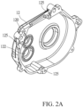
- the second casing member 12 is provided, on an inner side thereof, with a plurality of fastening holes 125 respectively corresponding to the fastening barrels 150 to be each receiving a fastening member 16 penetrating from one side of the support and separation board 15 through a corresponding one of the fastening barrels 150 to connect to the fastening hole 125 of the second casing member 12 (as shown in FIG. 2A ), so as to have the support and separation board 15 fastened to the second casing member 12 and sandwiched thereto by the first casing member 11, wherein the support and separation board 15 is provided for mounting and supporting the drive unit 20.
- the drive unit 20 is better shown in FIGS. 3 , 4 , and 5 .
- the drive unit 20 comprises an electromagnetic device 21 fastened to one side surface of the support and separation board 15.
- the electromagnetic device 21 comprises an output axle 22 penetrating through the support and separation board 15.
- the output axle 22 of the electromagnetic device 21 is rotatably mounted to the second casing member 12 that is opposite to the support and separation board 15 by a first bearing 220.
- the second casing member 12 is provided with a first axle trough 120 (as shown in FIG. 2A ) for mounting the first bearing 220.
- the drive unit 20 comprises a reduction gear 23 that is mounted to one side surface of the support and separation board 15 that is opposite to the electromagnetic device 21 and is in mating engagement with and driven by the output axle 22.
- the reduction gear 23 Two opposite ends of the reduction gear 23 are synchronously and rotatably supported on the support and separation board 15 and the second casing member 12 opposite thereto by means of a second bearing 231 and a third bearing 232, respectively.
- the second casing member 12 is provided with a second axle trough 122 (as shown in FIG. 2A ) for mounting the third bearing 232 in order to ensure stable mating engagement and smooth operation between the output axle 22 and the reduction gear 23.
- the support and separation board 15 is provided with a protection frame 25 mounted thereto at a location corresponding to where the output axle 22 and the reduction gear 23 engage with each other to provide an effect of protection and reduction of foreign objects falling therein.
- the reduction gear 23 comprises a first drive wheel 24 coaxially rotatable therewith.
- a transmission axle 28 is arranged between the first and second casing members 11, 12 to transmit power to outside of the housing 10, and the transmission axle 28 penetrates through the support and separation board 15. Further, the transmission axle 28 is provided with a second drive wheel 26 at a location corresponding to the first drive wheel 24 of the reduction gear 23, wherein the second drive wheel 26 is coaxially and synchronously rotatable with the transmission axle 28. At least one drive member 27 is arranged between and loops around the first and second drive wheels 24, 26, so that the reduction gear 23 may drive the transmission axle 28 by means of the drive member 27. Further, the first and second drive wheels 24, 26 and the drive member 27 can be selected as chain wheels and a chain, or pulleys and a belt.
- the first drive wheel 24 and the second drive wheel 26 may be set to have different ratios between diameters thereof to change a ratio of speeds thereof.
- the reduction gear 23, the first drive wheel 24, the second drive wheel, 26 and the drive member 27 jointly form a reduction and transmission mechanism of a loading path between the output axle 22 and the transmission axle 28.
- the housing 10 is provided, in the interior thereof, with a control board 30 that issues operation instructions and data, wherein the control board 30 at least comprises a microprocessor 31, and at least one sensor 32, at least one global positioning system (GPS) device 33, at least one transmission device 34, and at least one operation module 35 that are in connection with the microprocessor 31 for motor operation control, motor operation state detection, distance detection, carbon emission calculation, and data transmission, respectively.
- the control board 30 is arranged on one side surface of the support and separation board 15 that is opposite to the electromagnetic device 21, so that interference of the control board 30 by the electromagnetic device 21 on the opposite side of the support and separation board 15 can be reduced.
- the electromagnetic device 21 of the motor utilizes electromagnetism to make the output axle 22, which serves as a rotor, rotating at a high speed, which is then converted by the reduction and transmission mechanism to an increased torque for subsequently drive the transmission axle 28 that transmits the power to the outside of the housing 10, so as to allow the motor to drive an electrical vehicle to move, and as such, a motor structure that has a good structural strength and is not easily interfered with is formed.
- the support and separation board 15 arranged in the interior of the housing 10 can separate the electromagnetic device 21 and the control board 30 of the drive unit 20 from each other, so that electrical wave or magnetism of the electromagnetic device 21 interfering with the microprocessor 31, the sensor 32, the GPS device 33, the transmission device 34, or the operation module 35 arranged on the control board 30 can be reduce to thereby reduce occurrence of false operations.
- the motor structure of the present invention utilizes the arrangement that the support and separation board 15 is arranged and sandwiched in the interior of the housing 10 and the support and separation board 15 jointly supports the drive unit 20 and the reduction and transmission mechanism in the interior of the housing 10, so as to effectively enhance the structural strength and stability to effectively spread vibration of the operation thereof to reduce events of loosening or axis line shifting and abrading, and further, the support and separation board 15 is arranged to separate the electromagnetic device 21 and the control board 30 of the drive unit 20 to thereby provide certain protection to the control board 30 to reduce interference of the electrical components thereof by electrical waves or magnetism of the electromagnetic device 21 to reduce motor being influenced with respect to normal operation thereof by false operations, so as to greatly enhance practical utilization thereof.
Landscapes
- Engineering & Computer Science (AREA)
- Power Engineering (AREA)
- General Engineering & Computer Science (AREA)
- Mechanical Engineering (AREA)
- Microelectronics & Electronic Packaging (AREA)
- Connection Of Motors, Electrical Generators, Mechanical Devices, And The Like (AREA)
- Motor Or Generator Frames (AREA)
- Iron Core Of Rotating Electric Machines (AREA)
Abstract
Description
- The present invention relates generally to the technical field of motors.
- In a known drive motor structure of an electrical vehicle, an electromagnetic device and a transmission axle are directly mounted on a housing, while a reduction and transmission mechanism is arranged in a loading path between the electromagnetic device and the transmission axle and coupled thereto. The electromagnetic device, when subjected to electromagnetism to operate to drive the transmission axle, is affected by high-speed rotation and loading variation to generate vibration at high frequencies. Being subjected to the vibration of high frequencies, the housing may suffer loosening of fastening elements, so as to cause positional shifting of an axis line of the rotating parts to thereby induce abrasion and thus leading to damage or malfunction of the motor structure. Further, to control the operation and to detect a state of operation, the motor structure is often provided, in the interior thereof, with a control board that includes a plurality of electronic components. However, the control board is not properly protected and the electronic components arranged thereon are susceptible to inference by electrical waves or magnetism of the electromagnetic device, making the control board issuing incorrect instruction or data due to such interference.
- In other words, the motor of the known electrical vehicle suffers operation deficiency of easy damage and malfunction caused by the previously discussed insufficiency of supporting strength and susceptibility of the control board to inference.
- The primary objective of the present invention is to a motor structure that effectively enhances the structural strength and stability thereof in order to reduce events of loosening or axis line shifting and abrading resulting from vibration to thereby improve operation safety to further extend the service life of the motor.
- The secondary objective of the present invention is to provide a motor structure that allows a control board to be properly protected to reduce interference of electronic components arranged thereto by electrical waves or magnetism of an electromagnetic device in order to reduce normal operation of the motor being influenced by false operations.
-
-
FIG. 1 is a perspective view of the present invention. -
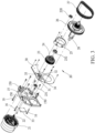
FIG. 2 is an exploded view of the present invention. -
FIG. 2A is a perspective view showing a second casing member of a housing of the present invention. -
FIG. 3 is an exploded view showing a drive unit of the present invention. -
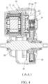
FIG. 4 is a cross-sectional view of the present invention taken along line A-A ofFIG. 1 . -
FIG. 5 is a cross-sectional view of the present invention taken along line B-B ofFIG. 1 . - A motor structure according to the present invention is generally illustrated in
FIGS. 1 ,2 , and2A , and comprises adrive unit 20 that is arranged in an interior of ahousing 10 to be oppositely connected to and fixedly mounted in thehousing 10. Thehousing 10 is formed of afirst casing member 11 and asecond casing member 12 that are oppositely fastened to and connected with each other. A support andseparation board 15 is arranged between the first andsecond casing members separation board 15 has a circumferential edge that is provided with a plurality offastening barrels 150 each of which has a through hole having two penetrating ends. Thesecond casing member 12 is provided, on an inner side thereof, with a plurality offastening holes 125 respectively corresponding to thefastening barrels 150 to be each receiving afastening member 16 penetrating from one side of the support andseparation board 15 through a corresponding one of thefastening barrels 150 to connect to thefastening hole 125 of the second casing member 12 (as shown inFIG. 2A ), so as to have the support andseparation board 15 fastened to thesecond casing member 12 and sandwiched thereto by thefirst casing member 11, wherein the support andseparation board 15 is provided for mounting and supporting thedrive unit 20. - The
drive unit 20 is better shown inFIGS. 3 ,4 , and5 . Thedrive unit 20 comprises anelectromagnetic device 21 fastened to one side surface of the support andseparation board 15. Theelectromagnetic device 21 comprises anoutput axle 22 penetrating through the support andseparation board 15. Further, theoutput axle 22 of theelectromagnetic device 21 is rotatably mounted to thesecond casing member 12 that is opposite to the support andseparation board 15 by a first bearing 220. Thesecond casing member 12 is provided with a first axle trough 120 (as shown inFIG. 2A ) for mounting the first bearing 220. Further, thedrive unit 20 comprises areduction gear 23 that is mounted to one side surface of the support andseparation board 15 that is opposite to theelectromagnetic device 21 and is in mating engagement with and driven by theoutput axle 22. Two opposite ends of thereduction gear 23 are synchronously and rotatably supported on the support andseparation board 15 and thesecond casing member 12 opposite thereto by means of a second bearing 231 and a third bearing 232, respectively. Thesecond casing member 12 is provided with a second axle trough 122 (as shown inFIG. 2A ) for mounting the third bearing 232 in order to ensure stable mating engagement and smooth operation between theoutput axle 22 and thereduction gear 23. Further, the support andseparation board 15 is provided with aprotection frame 25 mounted thereto at a location corresponding to where theoutput axle 22 and thereduction gear 23 engage with each other to provide an effect of protection and reduction of foreign objects falling therein. Further, thereduction gear 23 comprises afirst drive wheel 24 coaxially rotatable therewith. Atransmission axle 28 is arranged between the first andsecond casing members housing 10, and thetransmission axle 28 penetrates through the support andseparation board 15. Further, thetransmission axle 28 is provided with asecond drive wheel 26 at a location corresponding to thefirst drive wheel 24 of thereduction gear 23, wherein thesecond drive wheel 26 is coaxially and synchronously rotatable with thetransmission axle 28. At least onedrive member 27 is arranged between and loops around the first andsecond drive wheels reduction gear 23 may drive thetransmission axle 28 by means of thedrive member 27. Further, the first andsecond drive wheels drive member 27 can be selected as chain wheels and a chain, or pulleys and a belt. Thefirst drive wheel 24 and thesecond drive wheel 26 may be set to have different ratios between diameters thereof to change a ratio of speeds thereof. Thereduction gear 23, thefirst drive wheel 24, the second drive wheel, 26 and thedrive member 27 jointly form a reduction and transmission mechanism of a loading path between theoutput axle 22 and thetransmission axle 28. - Further, the
housing 10 is provided, in the interior thereof, with acontrol board 30 that issues operation instructions and data, wherein thecontrol board 30 at least comprises amicroprocessor 31, and at least onesensor 32, at least one global positioning system (GPS)device 33, at least onetransmission device 34, and at least oneoperation module 35 that are in connection with themicroprocessor 31 for motor operation control, motor operation state detection, distance detection, carbon emission calculation, and data transmission, respectively. Thecontrol board 30 is arranged on one side surface of the support andseparation board 15 that is opposite to theelectromagnetic device 21, so that interference of thecontrol board 30 by theelectromagnetic device 21 on the opposite side of the support andseparation board 15 can be reduced. - As such, the
electromagnetic device 21 of the motor utilizes electromagnetism to make theoutput axle 22, which serves as a rotor, rotating at a high speed, which is then converted by the reduction and transmission mechanism to an increased torque for subsequently drive thetransmission axle 28 that transmits the power to the outside of thehousing 10, so as to allow the motor to drive an electrical vehicle to move, and as such, a motor structure that has a good structural strength and is not easily interfered with is formed. - By means of the previously discussed structural arrangement, in a practical application of the present invention, as shown in
FIGS. 2 ,4 , and5 , when thedrive unit 20 of the motor is operating thetransmission axle 28 to transmit power to the outside, since the support andseparation board 15 is arranged and sandwiched between the first andsecond casing members housing 10, theoutput axle 22 of thedrive unit 20 and thereduction gear 23 of the reduction and transmission mechanism are jointly connected to thehousing 10 and the support andseparation board 15, and thus, thehousing 10 is effectively supported and high-frequency vibration caused by the high-speed operation of theelectromagnetic device 21 of thedrive unit 20 can be effectively distributed and absorbed to thereby reduce vibration and noise, so as to reduce events of loosening or axis line shifting resulting from high-frequency vibration and effectively reduce abrasion and failure of the rotating parts to thus extend the service life of the motor. - Further, the support and
separation board 15 arranged in the interior of thehousing 10 can separate theelectromagnetic device 21 and thecontrol board 30 of thedrive unit 20 from each other, so that electrical wave or magnetism of theelectromagnetic device 21 interfering with themicroprocessor 31, thesensor 32, theGPS device 33, thetransmission device 34, or theoperation module 35 arranged on thecontrol board 30 can be reduce to thereby reduce occurrence of false operations. - It is known from the above description that the motor structure of the present invention utilizes the arrangement that the support and
separation board 15 is arranged and sandwiched in the interior of thehousing 10 and the support andseparation board 15 jointly supports thedrive unit 20 and the reduction and transmission mechanism in the interior of thehousing 10, so as to effectively enhance the structural strength and stability to effectively spread vibration of the operation thereof to reduce events of loosening or axis line shifting and abrading, and further, the support andseparation board 15 is arranged to separate theelectromagnetic device 21 and thecontrol board 30 of thedrive unit 20 to thereby provide certain protection to thecontrol board 30 to reduce interference of the electrical components thereof by electrical waves or magnetism of theelectromagnetic device 21 to reduce motor being influenced with respect to normal operation thereof by false operations, so as to greatly enhance practical utilization thereof.
Claims (9)
- A motor structure, comprising:a housing (10), which is formed of a first casing member (11) and a second casing member (12) that are fastened to and connected with each other, a support and separation board (15) being arranged and clamped between the first and second casing members (11, 12); anda drive unit (20), which is arranged between the first and second casing members (11, 12) of the housing (10) and is supported by the support and separation board (15), the drive unit (20) comprising an electromagnetic device (21) mounted to one side surface of the support and separation board (15), the electromagnetic device (21) comprising an output axle (22) penetrating through the support and separation board (15), a transmission axle (28) being arranged between the first and second casing members (11, 12) of the housing (10) for transmitting power to outside of the housing (10), the transmission axle (28) penetrating through the support and separation board (15), a reduction and transmission mechanism being arranged in a loading path between the output axle (22) of the electromagnetic device (21) and the transmission axle (28).
- The motor structure according to claim 1, wherein the support and separation board (15) has a circumferential edge that is provided with a plurality of fastening barrels (150) having a through hole and two penetrating ends, and the second casing member (12) is provided, on an inner side, with a plurality of fastening holes (125) respectively corresponding to the fastening barrels (150) to each receive a fastening member (16) penetrating from one side of the support and separation board (15) through a corresponding one of the fastening barrels (150) to fix to the fastening hole (125) of the second casing member (12).
- The motor structure according to claim 1, wherein the output axle (22) of the electromagnetic device (21) is rotatably mounted by a first bearing (220) to the second casing member (12) that is opposite to the support and separation board (15), and the second casing member (12) comprises a first axle trough (120) corresponding to and mounting the first bearing (220).
- The motor structure according to claim 1, wherein the reduction and transmission mechanism comprises a reduction gear (23) arranged on one side surface of the support and separation board (15) that is opposite to the electromagnetic device (21) to be in mating engagement with and driven by the output axle (22); and the reduction gear (23) comprises a first drive wheel (24) coaxially rotatable therewith, and the transmission axle (28) is provided with a second drive wheel (26) corresponding to the first drive wheel (24), and a drive member (27) is arranged between the first and second drive wheels (24, 26) to establish a transmission arrangement, wherein a rotational speed ratio between the output axle (22) and the transmission axle (28) is variable by means of a change of a diameter ratio between the reduction gear (23) and the first drive wheel (24) and between the first drive wheel (24) and the second drive wheel (26).
- The motor structure according to claim 4, wherein two ends of the reduction gear (23) are synchronously and rotatably mounted on the support and separation board (15) and the second casing member (12) by a second bearing (231) and a third bearing (232) respectively, and the second casing member (12) comprises a second axle trough (122) to mount the third bearing (232).
- The motor structure according to claim 4, wherein the support and separation board (15) comprises a protection frame (25) mounted thereto at a location corresponding to where the output axle (22) and the reduction gear (23) are set in mating engagement with each other.
- The motor structure according to claim 4, wherein the first and second drive wheels (24, 26) and the drive member (27) are respectively chain wheels and a chain.
- The motor structure according to claim 1, wherein a control board (30) is arranged in an interior of the housing (10), and the control board (30) is arranged on one side surface of the support and separation board (15) that is opposite to the electromagnetic device (21).
- The motor structure according to claim 8, wherein the control board (30) at least comprises a microprocessor (31), and at least one sensor (32), at least one global positioning system (GPS) device (33), at least one transmission device (34), and at least one operation module (35) in connection with the microprocessor (31).
Applications Claiming Priority (1)
| Application Number | Priority Date | Filing Date | Title |
|---|---|---|---|
| TW111213269U TWM642787U (en) | 2022-11-30 | 2022-11-30 | motor structure |
Publications (3)
| Publication Number | Publication Date |
|---|---|
| EP4379238A1 true EP4379238A1 (en) | 2024-06-05 |
| EP4379238B1 EP4379238B1 (en) | 2025-08-20 |
| EP4379238C0 EP4379238C0 (en) | 2025-08-20 |
Family
ID=87805049
Family Applications (1)
| Application Number | Title | Priority Date | Filing Date |
|---|---|---|---|
| EP23206899.9A Active EP4379238B1 (en) | 2022-11-30 | 2023-10-31 | Motor structure |
Country Status (5)
| Country | Link |
|---|---|
| US (1) | US20240175484A1 (en) |
| EP (1) | EP4379238B1 (en) |
| JP (2) | JP7835447B2 (en) |
| CN (2) | CN221448200U (en) |
| TW (1) | TWM642787U (en) |
Citations (3)
| Publication number | Priority date | Publication date | Assignee | Title |
|---|---|---|---|---|
| US10890242B2 (en) * | 2017-06-01 | 2021-01-12 | Seiko Instruments Inc. | Gear box, driving device, and electronic apparatus |
| WO2021172095A1 (en) * | 2020-02-24 | 2021-09-02 | 株式会社デンソー | Actuator |
| JP2022136854A (en) * | 2021-03-08 | 2022-09-21 | 日本電産株式会社 | Drive device |
Family Cites Families (9)
| Publication number | Priority date | Publication date | Assignee | Title |
|---|---|---|---|---|
| JP5792542B2 (en) * | 2011-07-22 | 2015-10-14 | 株式会社日立産機システム | Pump device |
| JP2017101771A (en) * | 2015-12-03 | 2017-06-08 | Ntn株式会社 | Motor vehicle drive device |
| US10723182B2 (en) * | 2016-04-25 | 2020-07-28 | Itire, Llc | Wheel hub mounted vehicle data communications device incorporating a self-generating electrical power supply |
| CN112004705B (en) * | 2018-04-20 | 2024-01-12 | 麦格纳国际公司 | Chain driven electric drive gearbox |
| FR3086814B1 (en) * | 2018-09-28 | 2020-10-30 | Sonceboz Mechatronics Boncourt Sa | ELECTRIC ACTUATOR |
| JP7292956B2 (en) * | 2019-04-26 | 2023-06-19 | 株式会社シマノ | Drive unit for human powered vehicle |
| WO2021140712A1 (en) * | 2020-01-10 | 2021-07-15 | アイシン・エィ・ダブリュ株式会社 | Vehicular drive device |
| JP7631856B2 (en) * | 2021-02-08 | 2025-02-19 | ニデック株式会社 | Drive unit and electric vehicle |
| DE102023101989A1 (en) * | 2023-01-27 | 2024-08-01 | Minebea Mitsumi Inc. | Actuator with a guide element |
-
2022
- 2022-11-30 TW TW111213269U patent/TWM642787U/en unknown
-
2023
- 2023-10-31 US US18/498,045 patent/US20240175484A1/en active Pending
- 2023-10-31 EP EP23206899.9A patent/EP4379238B1/en active Active
- 2023-11-09 JP JP2023191891A patent/JP7835447B2/en active Active
- 2023-11-10 JP JP2023004091U patent/JP3245275U/en active Active
- 2023-11-17 CN CN202323106610.3U patent/CN221448200U/en active Active
- 2023-11-17 CN CN202311540111.7A patent/CN118117800A/en active Pending
Patent Citations (3)
| Publication number | Priority date | Publication date | Assignee | Title |
|---|---|---|---|---|
| US10890242B2 (en) * | 2017-06-01 | 2021-01-12 | Seiko Instruments Inc. | Gear box, driving device, and electronic apparatus |
| WO2021172095A1 (en) * | 2020-02-24 | 2021-09-02 | 株式会社デンソー | Actuator |
| JP2022136854A (en) * | 2021-03-08 | 2022-09-21 | 日本電産株式会社 | Drive device |
Also Published As
| Publication number | Publication date |
|---|---|
| JP7835447B2 (en) | 2026-03-25 |
| EP4379238B1 (en) | 2025-08-20 |
| EP4379238C0 (en) | 2025-08-20 |
| US20240175484A1 (en) | 2024-05-30 |
| TWM642787U (en) | 2023-06-21 |
| JP3245275U (en) | 2024-01-15 |
| JP2024079605A (en) | 2024-06-11 |
| CN221448200U (en) | 2024-07-30 |
| CN118117800A (en) | 2024-05-31 |
Similar Documents
| Publication | Publication Date | Title |
|---|---|---|
| JP4963006B2 (en) | Wireless sensor system and wheel bearing device with wireless sensor | |
| US20200215920A1 (en) | Vehicle drive device | |
| US7350806B2 (en) | Steering wheel with a static driver airbag module | |
| CN104290590B (en) | Driving apparatus | |
| US20100199796A1 (en) | Gear device and turning portion structure of industrial robot using the gear device | |
| US12325490B2 (en) | Wheel hub motor | |
| US6700244B2 (en) | Three-in-one structural combination magneto motor power system | |
| EP1992840A1 (en) | Drive pulleys | |
| US8628445B2 (en) | Vehicle-driving system | |
| US20240175484A1 (en) | Motor structure | |
| CN114918969B (en) | Mechanical arm joint | |
| US20220379866A1 (en) | Actuator for brake device | |
| JP2016080069A (en) | Planetary gear set | |
| CA1058911A (en) | Multiple power path concentric speed reducer | |
| CN114204746A (en) | Integrated steering engine device | |
| SU1754990A1 (en) | Planetary gearing | |
| JP4024633B2 (en) | Electromagnetic actuator and differential and power interrupting device using the same | |
| US20070186635A1 (en) | Tire information communication device | |
| US12455005B2 (en) | Axle assembly having a lubricant deflector | |
| US4404867A (en) | Gear unit | |
| CN118891459A (en) | Vehicle drive device | |
| KR100452477B1 (en) | Synchro-drive mobile robot with endless rotation type turret | |
| JP6049977B1 (en) | Motor equipment | |
| US12449249B1 (en) | Sensor assembly for a steering control lever of a mower | |
| EP4528998A1 (en) | Powertrain assembly, chassis and vehicle |
Legal Events
| Date | Code | Title | Description |
|---|---|---|---|
| PUAI | Public reference made under article 153(3) epc to a published international application that has entered the european phase |
Free format text: ORIGINAL CODE: 0009012 |
|
| STAA | Information on the status of an ep patent application or granted ep patent |
Free format text: STATUS: THE APPLICATION HAS BEEN PUBLISHED |
|
| AK | Designated contracting states |
Kind code of ref document: A1 Designated state(s): AL AT BE BG CH CY CZ DE DK EE ES FI FR GB GR HR HU IE IS IT LI LT LU LV MC ME MK MT NL NO PL PT RO RS SE SI SK SM TR |
|
| STAA | Information on the status of an ep patent application or granted ep patent |
Free format text: STATUS: REQUEST FOR EXAMINATION WAS MADE |
|
| 17P | Request for examination filed |
Effective date: 20241007 |
|
| RBV | Designated contracting states (corrected) |
Designated state(s): AL AT BE BG CH CY CZ DE DK EE ES FI FR GB GR HR HU IE IS IT LI LT LU LV MC ME MK MT NL NO PL PT RO RS SE SI SK SM TR |
|
| GRAP | Despatch of communication of intention to grant a patent |
Free format text: ORIGINAL CODE: EPIDOSNIGR1 |
|
| STAA | Information on the status of an ep patent application or granted ep patent |
Free format text: STATUS: GRANT OF PATENT IS INTENDED |
|
| INTG | Intention to grant announced |
Effective date: 20250402 |
|
| GRAS | Grant fee paid |
Free format text: ORIGINAL CODE: EPIDOSNIGR3 |
|
| GRAA | (expected) grant |
Free format text: ORIGINAL CODE: 0009210 |
|
| STAA | Information on the status of an ep patent application or granted ep patent |
Free format text: STATUS: THE PATENT HAS BEEN GRANTED |
|
| AK | Designated contracting states |
Kind code of ref document: B1 Designated state(s): AL AT BE BG CH CY CZ DE DK EE ES FI FR GB GR HR HU IE IS IT LI LT LU LV MC ME MK MT NL NO PL PT RO RS SE SI SK SM TR |
|
| REG | Reference to a national code |
Ref country code: GB Ref legal event code: FG4D |
|
| REG | Reference to a national code |
Ref country code: CH Ref legal event code: EP |
|
| REG | Reference to a national code |
Ref country code: DE Ref legal event code: R096 Ref document number: 602023005871 Country of ref document: DE |
|
| REG | Reference to a national code |
Ref country code: IE Ref legal event code: FG4D |
|
| U01 | Request for unitary effect filed |
Effective date: 20250821 |
|
| U07 | Unitary effect registered |
Designated state(s): AT BE BG DE DK EE FI FR IT LT LU LV MT NL PT RO SE SI Effective date: 20250828 |
|
| PG25 | Lapsed in a contracting state [announced via postgrant information from national office to epo] |
Ref country code: IS Free format text: LAPSE BECAUSE OF FAILURE TO SUBMIT A TRANSLATION OF THE DESCRIPTION OR TO PAY THE FEE WITHIN THE PRESCRIBED TIME-LIMIT Effective date: 20251220 |
|
| PG25 | Lapsed in a contracting state [announced via postgrant information from national office to epo] |
Ref country code: NO Free format text: LAPSE BECAUSE OF FAILURE TO SUBMIT A TRANSLATION OF THE DESCRIPTION OR TO PAY THE FEE WITHIN THE PRESCRIBED TIME-LIMIT Effective date: 20251120 |
|
| PG25 | Lapsed in a contracting state [announced via postgrant information from national office to epo] |
Ref country code: HR Free format text: LAPSE BECAUSE OF FAILURE TO SUBMIT A TRANSLATION OF THE DESCRIPTION OR TO PAY THE FEE WITHIN THE PRESCRIBED TIME-LIMIT Effective date: 20250820 |
|
| PG25 | Lapsed in a contracting state [announced via postgrant information from national office to epo] |
Ref country code: GR Free format text: LAPSE BECAUSE OF FAILURE TO SUBMIT A TRANSLATION OF THE DESCRIPTION OR TO PAY THE FEE WITHIN THE PRESCRIBED TIME-LIMIT Effective date: 20251121 |
|
| PG25 | Lapsed in a contracting state [announced via postgrant information from national office to epo] |
Ref country code: PL Free format text: LAPSE BECAUSE OF FAILURE TO SUBMIT A TRANSLATION OF THE DESCRIPTION OR TO PAY THE FEE WITHIN THE PRESCRIBED TIME-LIMIT Effective date: 20250820 |
|
| PG25 | Lapsed in a contracting state [announced via postgrant information from national office to epo] |
Ref country code: RS Free format text: LAPSE BECAUSE OF FAILURE TO SUBMIT A TRANSLATION OF THE DESCRIPTION OR TO PAY THE FEE WITHIN THE PRESCRIBED TIME-LIMIT Effective date: 20251120 |
|
| PG25 | Lapsed in a contracting state [announced via postgrant information from national office to epo] |
Ref country code: ES Free format text: LAPSE BECAUSE OF FAILURE TO SUBMIT A TRANSLATION OF THE DESCRIPTION OR TO PAY THE FEE WITHIN THE PRESCRIBED TIME-LIMIT Effective date: 20250820 |
|
| PG25 | Lapsed in a contracting state [announced via postgrant information from national office to epo] |
Ref country code: SM Free format text: LAPSE BECAUSE OF FAILURE TO SUBMIT A TRANSLATION OF THE DESCRIPTION OR TO PAY THE FEE WITHIN THE PRESCRIBED TIME-LIMIT Effective date: 20250820 |
|
| PG25 | Lapsed in a contracting state [announced via postgrant information from national office to epo] |
Ref country code: CZ Free format text: LAPSE BECAUSE OF FAILURE TO SUBMIT A TRANSLATION OF THE DESCRIPTION OR TO PAY THE FEE WITHIN THE PRESCRIBED TIME-LIMIT Effective date: 20250820 |
|
| PG25 | Lapsed in a contracting state [announced via postgrant information from national office to epo] |
Ref country code: SK Free format text: LAPSE BECAUSE OF FAILURE TO SUBMIT A TRANSLATION OF THE DESCRIPTION OR TO PAY THE FEE WITHIN THE PRESCRIBED TIME-LIMIT Effective date: 20250820 |
|
| U21 | Renewal fee for the european patent with unitary effect paid with additional fee |
Year of fee payment: 3 Effective date: 20260413 |
|
| PLBE | No opposition filed within time limit |
Free format text: ORIGINAL CODE: 0009261 |
|
| STAA | Information on the status of an ep patent application or granted ep patent |
Free format text: STATUS: NO OPPOSITION FILED WITHIN TIME LIMIT |
|
| PG25 | Lapsed in a contracting state [announced via postgrant information from national office to epo] |
Ref country code: MC Free format text: LAPSE BECAUSE OF FAILURE TO SUBMIT A TRANSLATION OF THE DESCRIPTION OR TO PAY THE FEE WITHIN THE PRESCRIBED TIME-LIMIT Effective date: 20250820 |
|
| REG | Reference to a national code |
Ref country code: CH Ref legal event code: L10 Free format text: ST27 STATUS EVENT CODE: U-0-0-L10-L00 (AS PROVIDED BY THE NATIONAL OFFICE) Effective date: 20260701 |
|
| 26N | No opposition filed |
Effective date: 20260521 |