EP4379174A1 - Knob holding structure and smart lock - Google Patents
Knob holding structure and smart lock Download PDFInfo
- Publication number
- EP4379174A1 EP4379174A1 EP23198476.6A EP23198476A EP4379174A1 EP 4379174 A1 EP4379174 A1 EP 4379174A1 EP 23198476 A EP23198476 A EP 23198476A EP 4379174 A1 EP4379174 A1 EP 4379174A1
- Authority
- EP
- European Patent Office
- Prior art keywords
- knob
- holder
- holding structure
- pinching
- pair
- Prior art date
- Legal status (The legal status is an assumption and is not a legal conclusion. Google has not performed a legal analysis and makes no representation as to the accuracy of the status listed.)
- Pending
Links
Images

Classifications
-
- G—PHYSICS
- G07—CHECKING-DEVICES
- G07C—TIME OR ATTENDANCE REGISTERS; REGISTERING OR INDICATING THE WORKING OF MACHINES; GENERATING RANDOM NUMBERS; VOTING OR LOTTERY APPARATUS; ARRANGEMENTS, SYSTEMS OR APPARATUS FOR CHECKING NOT PROVIDED FOR ELSEWHERE
- G07C9/00—Individual registration on entry or exit
- G07C9/00174—Electronically operated locks; Circuits therefor; Nonmechanical keys therefor, e.g. passive or active electrical keys or other data carriers without mechanical keys
- G07C9/00944—Details of construction or manufacture
-
- E—FIXED CONSTRUCTIONS
- E05—LOCKS; KEYS; WINDOW OR DOOR FITTINGS; SAFES
- E05B—LOCKS; ACCESSORIES THEREFOR; HANDCUFFS
- E05B47/00—Operating or controlling locks or other fastening devices by electric or magnetic means
- E05B47/02—Movement of the bolt by electromagnetic means; Adaptation of locks, latches, or parts thereof, for movement of the bolt by electromagnetic means
-
- E—FIXED CONSTRUCTIONS
- E05—LOCKS; KEYS; WINDOW OR DOOR FITTINGS; SAFES
- E05B—LOCKS; ACCESSORIES THEREFOR; HANDCUFFS
- E05B17/00—Accessories in connection with locks
- E05B17/22—Means for operating or controlling lock or fastening device accessories, i.e. other than the fastening members, e.g. switches, indicators
-
- E—FIXED CONSTRUCTIONS
- E05—LOCKS; KEYS; WINDOW OR DOOR FITTINGS; SAFES
- E05B—LOCKS; ACCESSORIES THEREFOR; HANDCUFFS
- E05B49/00—Electric permutation locks; Circuits therefor ; Mechanical aspects of electronic locks; Mechanical keys therefor
-
- G—PHYSICS
- G07—CHECKING-DEVICES
- G07C—TIME OR ATTENDANCE REGISTERS; REGISTERING OR INDICATING THE WORKING OF MACHINES; GENERATING RANDOM NUMBERS; VOTING OR LOTTERY APPARATUS; ARRANGEMENTS, SYSTEMS OR APPARATUS FOR CHECKING NOT PROVIDED FOR ELSEWHERE
- G07C9/00—Individual registration on entry or exit
- G07C9/00174—Electronically operated locks; Circuits therefor; Nonmechanical keys therefor, e.g. passive or active electrical keys or other data carriers without mechanical keys
- G07C9/00563—Electronically operated locks; Circuits therefor; Nonmechanical keys therefor, e.g. passive or active electrical keys or other data carriers without mechanical keys using personal physical data of the operator, e.g. finger prints, retinal images, voicepatterns
-
- E—FIXED CONSTRUCTIONS
- E05—LOCKS; KEYS; WINDOW OR DOOR FITTINGS; SAFES
- E05B—LOCKS; ACCESSORIES THEREFOR; HANDCUFFS
- E05B47/00—Operating or controlling locks or other fastening devices by electric or magnetic means
- E05B2047/0083—Devices of electrically driving keys, e.g. to facilitate opening
-
- E—FIXED CONSTRUCTIONS
- E05—LOCKS; KEYS; WINDOW OR DOOR FITTINGS; SAFES
- E05B—LOCKS; ACCESSORIES THEREFOR; HANDCUFFS
- E05B47/00—Operating or controlling locks or other fastening devices by electric or magnetic means
- E05B2047/0091—Retrofittable electric locks, e.g. an electric module can be attached to an existing manual lock
-
- E—FIXED CONSTRUCTIONS
- E05—LOCKS; KEYS; WINDOW OR DOOR FITTINGS; SAFES
- E05B—LOCKS; ACCESSORIES THEREFOR; HANDCUFFS
- E05B47/00—Operating or controlling locks or other fastening devices by electric or magnetic means
- E05B47/0001—Operating or controlling locks or other fastening devices by electric or magnetic means with electric actuators; Constructional features thereof
- E05B47/0012—Operating or controlling locks or other fastening devices by electric or magnetic means with electric actuators; Constructional features thereof with rotary electromotors
Definitions
- a certain aspect of the embodiments relates to a knob holding structure and a smart lock.
- a conventional smart lock is a device which unlocks and locks a door by password input, fingerprint authentication, or remote control from an electronic device such as a smartphone, and has a holding means for holding a knob to unlock and lock the door such as a thumb-turn, and a drive means for rotating the holding means.
- a mechanism has been proposed, wherein an error in a mounting position of a smart lock with respect to a door can be absorbed by the mechanism.
- a smart lock device which has a configuration in which a soft rubber sleeve is inserted inside a cover configured to fix a thumb-turn.
- a knob holding structure comprises: a holder; a pair of pinching members configured to hold a knob and arranged opposed to each other in the holder; and an elastic member configured to support the pair of pinching members so that each pinching member can be displaced relative to an inner surface of the holder, and to bias the pinching members in a direction so as to approach each other.
- a smart lock comprises: the above knob holding structure and a drive mechanism configured to rotationally drive the holder.
- the pair of pinching members when attaching the smart lock to a door, etc., can be automatically elastically displaced corresponding to the position and/or the shape of the knob. Therefore, the knob can be appropriately held while greatly reducing the amount of work required of the operator.
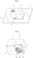
- FIG. 1 is a perspective view of a smart lock 10 according to a preferred embodiment
- FIG. 2 is a perspective view of the smart lock 10 viewed from a different angle than FIG. 1
- the smart lock 10 includes a housing 12, a knob holding structure 14 arranged in the housing 12, and a drive mechanism 50 (see FIG. 7 ) arranged in the housing 12 and configured to rotationally drive the knob holding structure 14 relative to the housing 12.
- the smart lock 10 is configured, for example, to rotate a thumb-turn type knob 22 arranged on a door 20, partially shown in FIG. 3 , by remote control.
- the drive mechanism 50 can rotationally drive the knob holding structure 14 by remote control from an electronic device (not shown) such as a smart phone, thereby rotating the knob 22.
- the knob 22 is not limited to a thumb-turn, and may include a lever, a latch, etc., which locks and unlocks the door by being rotated or moved.
- the smart lock 10 can be attached to door 20 by various means.
- an attachment surface 18 of the smart lock 10 as shown in FIG. 2 can be adhered to the door 20 in place by using a double-sided adhesive tape or adhesive agent, etc. (not shown).
- the smart lock 10 may have an operation knob 16 connected to the knob holding structure 14 so that the knob 22 may also be manually rotated.
- the operation knob 16 is connected to, for example, a rotary shaft part 44 as shown in FIG. 6 .
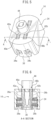
- FIG. 4 is a view of a configuration example of the knob holding structure 14 as viewed from the side attached to the door 20 (hereinafter, also referred to as the bottom side).
- the knob holding structure 14 includes a holder 24, a pair of pinching members 26a and 26b configured to hold the knob 22 and arranged opposed to each other in the holder 24, and elastic members 28a and 28b.
- the elastic members 28a and 28b are configured to support the pair of pinching members 26a and 26b so that each pinching member can be displaced relative to an inner surface of the holder 24, and to bias the pinching members 26a and 26b in a direction to approach each other, respectively.
- the pinching members 26a and 26b are plate-like members (hereinafter also referred to as pinching plates), and the elastic members 28a and 28b are a plurality of coil springs. There is no particular restriction on the number of coil springs.
- the pair of pinching plates 26a and 26b are arranged apart from each other by a predetermined distance on the bottom side.
- the pair of pinching plates 26a and 26b are biased toward each other by the coil springs 28a and 28b, respectively, and are retained so as to be separated by a constant distance by a support part 30 constructed as a part of the holder 24.
- the support part 30 is formed as a substantially T-shaped part by forming slits 32a and 32b in a portion of the holder 24 in the direction in which the pair of pinching plates 26a and 26b can move toward and away from each other.
- the pinching plates 26a and 26b have protrusions 34a and 34b capable of moving in the slits 32a and 32b, respectively. Due to such a configuration, the pinching plates 26a and 26b can be elastically displaced in the direction of contacting and separating from each other within a range corresponding to the lengths of the slits 32a and 32b in the directions of the displacements of the pinching plates 26a and 26b, respectively.
- the slits 32a and 32b allow the moving direction of the pinching plates 26a and 26b to be substantially limited to the contact and separation direction, the motions of the pinching plates 26a and 26b can be stabilized and the knob 22 can be held appropriately.
- this is merely an example. Therefore, even when support part 30 is not provided, the pair of pinching plates 26a and 26b can be separated from each other by a proper distance by appropriately selecting the number, size, spring constant, etc., of each of the coil springs 28a and 28b.
- an operator manipulates the housing 12 so that the knob 22 is inserted into a gap 36 between the pair of pinching plates 26a and 26b.
- the gap 36 has a width somewhat less than the thickness of the knob 22 before attachment, the pinching plates 26a and 26b are supported by the coil springs 28a and 28b, respectively, as described above.
- the housing 12 is pressed against the knob 22, at least one of the pinching plates 26a and 26b is elastically displaced in the direction of contacting and separating from each other. Therefore, even when the operator does not precisely position the housing 12 with respect to the knob 22, the knob 22 can be smoothly inserted into the gap 36.
- the pinching plates 26a and 26b have tapered surfaces 38a and 38b at a portion (end surface) facing the bottom side (i.e., at a side into which the knob 22 is inserted), respectively.
- the pair of pinching plates 26a and 26b may be in contact with each other before being attached.
- the pinching plates 26a and 26b are separated from each other by the predetermined distance due to the above support part 30, from the viewpoint of ease of insertion of the knob 22.
- the tapered surface may be provided only on one of the pinching plates.
- the knob 22 When the knob 22 is inserted into the gap 36, the distance between the pinching plates 26a and 26b is increased against the spring pressure of the coil springs 28a and 28b, and the knob 22 is pinched between the pinching plates 26a and 26b. At this time, the position of the holder 24 relative to the knob 22 is automatically adjusted so that the center of rotation of the knob 22 and the center of rotation of the holder 24 are aligned by the balance of the spring pressure of the coil springs 28a and 28b. Therefore, the operator can attach the smart lock 10 to the door 20 with sufficient accuracy for practical use by a simple operation which does not require time-consuming positioning or adjustment.
- the knob 22 In the state in which the knob 22 is held by the holder 24, more specifically in the state in which the knob 22 is pinched between the pinching plates 26a and 26b, the knob 22 can be rotated together with the holder 24 by the drive mechanism 50 as described later. Further, when the rotation angle of the holder 24 becomes larger than the maximum rotation angle based on the specifications, etc., of the knob 22, at least one of the coil springs 28a and 28b can be elastically displaced so as to absorb excessive rotational movement of the holder 24, thereby preventing excessive force from being applied to the knob 22.
- FIG. 5 is a view of the knob holding structure 14 viewed from the top side opposite to the bottom side
- FIG. 6 is a cross-sectional view taken along a line A-A in FIG. 5
- the holder 24 is configured to support the pinching plates 26a and 26b so as to be capable of swinging in direction toward and away from each other.
- holes or recesses 40a and 40b are formed in an upper surface of the holder 24, and protrusions 42a and 42b formed on upper surfaces of the pinching plates 26a and 26b are engaged with holes 40a and 40b, respectively. Due to such a configuration, as shown in FIG. 6 , the pinching plates 26a and 26b are capable of swinging about the holes 40a and 40b, respectively, and thus the knob 22 can be stably pinched and held while being attached.
- each member constituting the knob holding structure 14 the holder 24 and the pinching plates 26a and 26b are preferably made of resin from the viewpoint of ease of manufacture and weight.
- the coil springs 28a and 28b are preferably made of metal. Elastic bodies other than the coil springs can also be used, such as leaf springs, rubber, and sponges, etc.
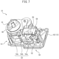
- FIG. 7 shows a configuration example of a drive mechanism 50 for rotationally driving the knob holding structure 14.
- the drive mechanism 50 has a drive motor 52 and a gear unit 54 configured to transmit the rotational torque of the drive motor 52 to the holder 24, and the entirety of the drive mechanism 50 can be accommodated within the housing 12.
- FIG. 7 only a bottom part 62 having the attachment surface 18 ( FIG. 2 ) of the housing 12 is shown for the purpose of explanation.
- a control board 58 on which a processor 56, etc., is mounted can also be accommodated.
- the processor 56 is configured to control the drive motor 52 based on remote control from the electronic device such as a smart phone.
- the gear unit 54 has at least one gear, and in the illustrated example, has three gears 54a, 54b and 54c engaged in series.
- the gear 54c is engaged with the rotary shaft part 44 (see FIG. 5 ) of the holder 24, the knob 22 held by the holder 24 is rotated by the rotation of the motor 52.
- this is merely an example, and the number of the gears and the number of teeth of each gear constituting the gear unit 54 can be appropriately selected, based on the specifications of the drive motor 52 and/or the desired rotational speed of the knob 22, etc.
- the knob holding structure 14 be also manually rotatable. For example, by connecting a rotary shaft part 60 of the operation knob 16 to the rotary shaft part 44 (see FIG. 5 ) of the holder 24, the knob 22 held by the holder 24 can be rotated manually rotated when the operator rotates the operation knob 16.
Landscapes
- Physics & Mathematics (AREA)
- General Physics & Mathematics (AREA)
- Engineering & Computer Science (AREA)
- Manufacturing & Machinery (AREA)
- Electromagnetism (AREA)
- Casings For Electric Apparatus (AREA)
- Lock And Its Accessories (AREA)
Abstract
Description
- This application is based upon and claims the benefit of priority of the prior
Japanese Patent Application No. 2022-191806 filed on November 30, 2022 - A certain aspect of the embodiments relates to a knob holding structure and a smart lock.
- A conventional smart lock is a device which unlocks and locks a door by password input, fingerprint authentication, or remote control from an electronic device such as a smartphone, and has a holding means for holding a knob to unlock and lock the door such as a thumb-turn, and a drive means for rotating the holding means.
- A mechanism has been proposed, wherein an error in a mounting position of a smart lock with respect to a door can be absorbed by the mechanism. For example, a smart lock device is well known which has a configuration in which a soft rubber sleeve is inserted inside a cover configured to fix a thumb-turn.
- Also, there is known a technique for correcting a deviation or eccentricity between a door lock and a door installation mechanism, by using rubber, sponge, robot fingers, etc. as a coupling for rotating the thumb-turn.
-
- [Patent Literature 1]
JP 2020-204164 A - [Patent Literature 2]
JP 2018-028259 A - When attaching a smart lock to a door, etc., in order to securely fix a knob holding means to a knob with their rotation centers aligned, the two are positioned and then fixed using screws, etc. However, such positioning and fixing operations are complicated and troublesome work for an operator.
- Although some techniques for absorbing the positioning error have been proposed as described above, there is a demand for a knob holding structure and a smart lock having a simpler configuration and a structure which can improve the efficiency of operations related to positioning and fixing.
- A knob holding structure according to one aspect of the present disclosure comprises: a holder; a pair of pinching members configured to hold a knob and arranged opposed to each other in the holder; and an elastic member configured to support the pair of pinching members so that each pinching member can be displaced relative to an inner surface of the holder, and to bias the pinching members in a direction so as to approach each other.
- A smart lock according to another aspect of the present disclosure comprises: the above knob holding structure and a drive mechanism configured to rotationally drive the holder.
- According to the present disclosure, when attaching the smart lock to a door, etc., the pair of pinching members can be automatically elastically displaced corresponding to the position and/or the shape of the knob. Therefore, the knob can be appropriately held while greatly reducing the amount of work required of the operator.
-
-
FIG. 1 is a perspective view of a smart lock according to an embodiment. -
FIG. 2 is a perspective view of the smart lock ofFIG. 1 viewed from another angle. -
FIG. 3 is a perspective view showing an object to which the smart lock is attached. -
FIG. 4 is a perspective view of a configuration example of a knob holding structure. -
FIG. 5 is a perspective view of the knob holding structure ofFIG. 4 viewed from another angle. -
FIG. 6 is a cross-sectional view along an A-A line ofFIG. 5 . -
FIG. 7 is a perspective view of a drive mechanism of the knob holding structure. - Hereinafter, a description will be given of the embodiment of the present invention with reference to the drawings.
-
FIG. 1 is a perspective view of asmart lock 10 according to a preferred embodiment, andFIG. 2 is a perspective view of thesmart lock 10 viewed from a different angle thanFIG. 1 . Thesmart lock 10 includes ahousing 12, aknob holding structure 14 arranged in thehousing 12, and a drive mechanism 50 (seeFIG. 7 ) arranged in thehousing 12 and configured to rotationally drive theknob holding structure 14 relative to thehousing 12. Thesmart lock 10 is configured, for example, to rotate a thumb-turn type knob 22 arranged on adoor 20, partially shown inFIG. 3 , by remote control. For example, while theknob holding structure 14 holds theknob 22, thedrive mechanism 50 can rotationally drive theknob holding structure 14 by remote control from an electronic device (not shown) such as a smart phone, thereby rotating theknob 22. Theknob 22 is not limited to a thumb-turn, and may include a lever, a latch, etc., which locks and unlocks the door by being rotated or moved. - The
smart lock 10 can be attached to door 20 by various means. For example, anattachment surface 18 of thesmart lock 10 as shown inFIG. 2 can be adhered to thedoor 20 in place by using a double-sided adhesive tape or adhesive agent, etc. (not shown). As also shown inFIG. 1 , thesmart lock 10 may have anoperation knob 16 connected to theknob holding structure 14 so that theknob 22 may also be manually rotated. Theoperation knob 16 is connected to, for example, arotary shaft part 44 as shown inFIG. 6 . -
FIG. 4 is a view of a configuration example of theknob holding structure 14 as viewed from the side attached to the door 20 (hereinafter, also referred to as the bottom side). Theknob holding structure 14 includes aholder 24, a pair of pinchingmembers knob 22 and arranged opposed to each other in theholder 24, andelastic members elastic members members holder 24, and to bias the pinchingmembers members elastic members - The pair of pinching
plates plates coil springs support part 30 constructed as a part of theholder 24. - More specifically, the
support part 30 is formed as a substantially T-shaped part by formingslits holder 24 in the direction in which the pair of pinchingplates plates protrusions slits plates slits plates slits plates plates knob 22 can be held appropriately. However, this is merely an example. Therefore, even whensupport part 30 is not provided, the pair of pinchingplates coil springs - When attaching the
smart lock 10 to thedoor 20 as shown inFIG. 1 , an operator manipulates thehousing 12 so that theknob 22 is inserted into agap 36 between the pair of pinchingplates gap 36 have a width somewhat less than the thickness of theknob 22 before attachment, the pinchingplates coil springs housing 12 is pressed against theknob 22, at least one of the pinchingplates housing 12 with respect to theknob 22, theknob 22 can be smoothly inserted into thegap 36. - In order to facilitate the insertion of the
knob 22, as shown inFIG. 4 , it is preferable that the pinchingplates surfaces knob 22 is inserted), respectively. Depending on the shapes of thetapered surfaces plates plates above support part 30, from the viewpoint of ease of insertion of theknob 22. In addition, the tapered surface may be provided only on one of the pinching plates. - When the
knob 22 is inserted into thegap 36, the distance between the pinchingplates coil springs knob 22 is pinched between the pinchingplates holder 24 relative to theknob 22 is automatically adjusted so that the center of rotation of theknob 22 and the center of rotation of theholder 24 are aligned by the balance of the spring pressure of thecoil springs smart lock 10 to thedoor 20 with sufficient accuracy for practical use by a simple operation which does not require time-consuming positioning or adjustment. - In the state in which the
knob 22 is held by theholder 24, more specifically in the state in which theknob 22 is pinched between the pinchingplates knob 22 can be rotated together with theholder 24 by thedrive mechanism 50 as described later. Further, when the rotation angle of theholder 24 becomes larger than the maximum rotation angle based on the specifications, etc., of theknob 22, at least one of thecoil springs holder 24, thereby preventing excessive force from being applied to theknob 22. -
FIG. 5 is a view of theknob holding structure 14 viewed from the top side opposite to the bottom side, andFIG. 6 is a cross-sectional view taken along a line A-A inFIG. 5 . Theholder 24 is configured to support the pinchingplates holder 24, andprotrusions plates holes FIG. 6 , the pinchingplates holes knob 22 can be stably pinched and held while being attached. - Although there are no particular restrictions on the material of each member constituting the
knob holding structure 14, theholder 24 and thepinching plates coil springs -
FIG. 7 shows a configuration example of adrive mechanism 50 for rotationally driving theknob holding structure 14. Thedrive mechanism 50 has adrive motor 52 and agear unit 54 configured to transmit the rotational torque of thedrive motor 52 to theholder 24, and the entirety of thedrive mechanism 50 can be accommodated within thehousing 12. However, inFIG. 7 , only abottom part 62 having the attachment surface 18 (FIG. 2 ) of thehousing 12 is shown for the purpose of explanation. - Within the
housing 12, acontrol board 58 on which aprocessor 56, etc., is mounted can also be accommodated. Theprocessor 56 is configured to control thedrive motor 52 based on remote control from the electronic device such as a smart phone. - The
gear unit 54 has at least one gear, and in the illustrated example, has threegears gear 54c is engaged with the rotary shaft part 44 (seeFIG. 5 ) of theholder 24, theknob 22 held by theholder 24 is rotated by the rotation of themotor 52. However, this is merely an example, and the number of the gears and the number of teeth of each gear constituting thegear unit 54 can be appropriately selected, based on the specifications of thedrive motor 52 and/or the desired rotational speed of theknob 22, etc. - It is preferable that the
knob holding structure 14 be also manually rotatable. For example, by connecting arotary shaft part 60 of theoperation knob 16 to the rotary shaft part 44 (seeFIG. 5 ) of theholder 24, theknob 22 held by theholder 24 can be rotated manually rotated when the operator rotates theoperation knob 16. - All examples and conditional language provided herein are intended for the purposes of aiding the reader in understanding the invention and the concepts contributed by the inventor to further the art, and are not to be construed as limitations to such specifically recited examples and conditions, nor does the organization of such examples in the specification relate to a showing of the superiority and inferiority of the invention. Although one or more embodiments of the present invention have been described in detail, it should be understood that the various changes, substitutions, and alterations can be made hereto without departing from the spirit and scope of the invention.
Claims (6)
- A knob holding structure (14) comprising:a holder (24);a pair of pinching members (26a, 26b) configured to hold a knob (22) and arranged opposed to each other in the holder; andan elastic member (28a, 28b) configured to support the pair of pinching members so that each pinching member can be displaced relative to an inner surface of the holder, and to bias the pinching members in a direction so as to approach each other.
- The knob holding structure (14) according to claim 1, wherein the holder (24) has a slit (32a, 32b) configured to support the pair of pinching members and extending in a direction in which the pair of pinching members (26a, 26b) contact and separate from each other.
- The knob holding structure (14) according to claim 1 or claim 2, wherein the pair of pinching members (26a, 26b) are configured to be swingable about a part of the holder as a fulcrum.
- The knob holding structure (14) according to any of the preceding claims, wherein a least one of the pair of pinching members (26a, 26b) has a tapered surface (38a, 38b) at a side into which the knob is inserted.
- A smart lock (10) comprising:a knob holding structure (14) comprising:a holder (24);a pair of pinching members (26a, 26b) configured to hold a knob (22) and arranged opposed to each other in the holder; andan elastic member (28a, 28b) configured to support the pair of pinching members so that each pinching member can be displaced relative to an inner surface of the holder, and to bias the pinching members in a direction so as to approach each other; anda drive mechanism (50) configured to rotationally drive the holder.
- The smart lock (10) according to claim 5, wherein the knob holding structure (14) is in accordance with any of claims 1 to 4.
Applications Claiming Priority (1)
| Application Number | Priority Date | Filing Date | Title |
|---|---|---|---|
| JP2022191806A JP2024079086A (en) | 2022-11-30 | 2022-11-30 | Knob retention structure and smart lock |
Publications (1)
| Publication Number | Publication Date |
|---|---|
| EP4379174A1 true EP4379174A1 (en) | 2024-06-05 |
Family
ID=88206891
Family Applications (1)
| Application Number | Title | Priority Date | Filing Date |
|---|---|---|---|
| EP23198476.6A Pending EP4379174A1 (en) | 2022-11-30 | 2023-09-20 | Knob holding structure and smart lock |
Country Status (4)
| Country | Link |
|---|---|
| US (1) | US12322232B2 (en) |
| EP (1) | EP4379174A1 (en) |
| JP (1) | JP2024079086A (en) |
| CN (1) | CN118110384A (en) |
Families Citing this family (1)
| Publication number | Priority date | Publication date | Assignee | Title |
|---|---|---|---|---|
| US20240344357A1 (en) * | 2022-11-02 | 2024-10-17 | Zachary Dan Griffith | Universal door lock indicating devices, kits, and methods |
Citations (5)
| Publication number | Priority date | Publication date | Assignee | Title |
|---|---|---|---|---|
| US20160040452A1 (en) * | 2014-08-06 | 2016-02-11 | Che-Ming KU | Door mount mechanism for a smart lock system |
| JP2018028259A (en) | 2014-10-08 | 2018-02-22 | キャンディー・ハウス・インコーポレイテッド | Gear assembly and door installation mechanism including the same |
| US20180061163A1 (en) * | 2016-08-30 | 2018-03-01 | Candy House Inc. | Control device for a door lock |
| DE102017127982A1 (en) * | 2017-11-27 | 2019-05-29 | Eq-3 Holding Gmbh | Key actuator |
| JP2020204164A (en) | 2019-06-14 | 2020-12-24 | ブロックチェーンロック株式会社 | Power transmission mechanism and smart lock device with the same |
Family Cites Families (18)
| Publication number | Priority date | Publication date | Assignee | Title |
|---|---|---|---|---|
| US2280553A (en) * | 1940-03-04 | 1942-04-21 | Harry W Srygley | Attachment for safe knobs |
| US2610877A (en) * | 1950-03-31 | 1952-09-16 | Clark H Weaver | Attachment for door knobs |
| US4503692A (en) * | 1982-08-23 | 1985-03-12 | Grint Dean R | Protective doorknob encasement device |
| US5979199A (en) * | 1996-09-13 | 1999-11-09 | Access Technologies, Inc. | Electrically operated actuator |
| US6122945A (en) * | 1999-02-11 | 2000-09-26 | Grant; Jackie N. | Keyless door knob security device with stabilizer arm |
| US6658906B1 (en) * | 2001-01-22 | 2003-12-09 | James H. Wright | Doorknob disabling device |
| BE1014374A3 (en) * | 2001-09-19 | 2003-09-02 | Parys Remi E Van | Control device for a lock mechanism. |
| US6687957B2 (en) * | 2002-05-20 | 2004-02-10 | K I Industries, Inc. | Two-part knob and method of making same |
| US20060006678A1 (en) * | 2004-05-27 | 2006-01-12 | Herron Roy H Jr | Door handle cover |
| US7334824B2 (en) * | 2004-10-12 | 2008-02-26 | Kidco, Inc. | Door lever lock |
| EP2050902A1 (en) * | 2007-10-18 | 2009-04-22 | USM Holding AG | Mechatronic furniture lock |
| US7802828B2 (en) * | 2008-03-14 | 2010-09-28 | Outpace Innovations, Llc | Child safety cover |
| JP5932525B2 (en) * | 2012-07-03 | 2016-06-08 | Idec株式会社 | Operating member locking device and operating device provided with the operating member locking device |
| CN202706683U (en) * | 2012-07-13 | 2013-01-30 | 胡昌阵 | Inner knob structure for core-insert door lock |
| US10184272B2 (en) * | 2015-07-01 | 2019-01-22 | Dominick S. LEE | Installation-free rechargeable door locking apparatus, systems and methods |
| US9672674B2 (en) * | 2015-07-06 | 2017-06-06 | Acsys Ip Holding, Inc. | Systems and methods for secure lock systems with redundant access control |
| CN106917540A (en) * | 2015-12-28 | 2017-07-04 | 伟林电子股份有限公司 | Loosening structure of intelligent lock |
| CN209761059U (en) * | 2019-03-15 | 2019-12-10 | 温州市至信锁业有限公司 | Intelligent lock |
-
2022
- 2022-11-30 JP JP2022191806A patent/JP2024079086A/en active Pending
-
2023
- 2023-09-20 EP EP23198476.6A patent/EP4379174A1/en active Pending
- 2023-10-16 US US18/487,927 patent/US12322232B2/en active Active
- 2023-10-19 CN CN202311352471.4A patent/CN118110384A/en not_active Withdrawn
Patent Citations (5)
| Publication number | Priority date | Publication date | Assignee | Title |
|---|---|---|---|---|
| US20160040452A1 (en) * | 2014-08-06 | 2016-02-11 | Che-Ming KU | Door mount mechanism for a smart lock system |
| JP2018028259A (en) | 2014-10-08 | 2018-02-22 | キャンディー・ハウス・インコーポレイテッド | Gear assembly and door installation mechanism including the same |
| US20180061163A1 (en) * | 2016-08-30 | 2018-03-01 | Candy House Inc. | Control device for a door lock |
| DE102017127982A1 (en) * | 2017-11-27 | 2019-05-29 | Eq-3 Holding Gmbh | Key actuator |
| JP2020204164A (en) | 2019-06-14 | 2020-12-24 | ブロックチェーンロック株式会社 | Power transmission mechanism and smart lock device with the same |
Also Published As
| Publication number | Publication date |
|---|---|
| JP2024079086A (en) | 2024-06-11 |
| US12322232B2 (en) | 2025-06-03 |
| US20240177552A1 (en) | 2024-05-30 |
| CN118110384A (en) | 2024-05-31 |
Similar Documents
| Publication | Publication Date | Title |
|---|---|---|
| US8418319B2 (en) | Hinge mechanism | |
| EP0911543A2 (en) | Actuator | |
| US12322232B2 (en) | Knob holding structure and smart lock | |
| CN111749974B (en) | Lock-release mechanism, opening and closing device and electronic equipment | |
| CN111694400B (en) | Buckle mechanism and bearing structure of electronic device | |
| CN110556967A (en) | linear drive | |
| US20230323710A1 (en) | Handle device for vehicle | |
| EP3748110B1 (en) | Inside handle device | |
| WO2007020691A1 (en) | Rotation output device | |
| CN111152247B (en) | manipulator | |
| CN111112970B (en) | Assembling device | |
| KR20200002252U (en) | Spring forming machine having tool rotation and tool retraction capabilities | |
| CN115263904A (en) | Rotating structure and electronic equipment | |
| JP7071017B1 (en) | Holding mechanism, method | |
| US20160352256A1 (en) | Vibration wave motor | |
| JP6196080B2 (en) | Pick and place unit | |
| JP6290288B2 (en) | Gear unit and electronic lock | |
| CN111278251B (en) | Locking Mechanisms, Vehicle Displays and Vehicles | |
| CN107450761B (en) | Operating device and method for producing same | |
| JP7799923B2 (en) | Clamping mechanism and electronic lock | |
| CN116871874B (en) | Elastic centering alignment device | |
| CN223533225U (en) | Paper blocking structure and printer | |
| US11502624B2 (en) | Vibration type actuator, rotationally driving apparatus, and image pickup apparatus | |
| JP7829142B2 (en) | Operation detection device and door opening/closing control system | |
| CN219220060U (en) | Door lock clutch and door lock |
Legal Events
| Date | Code | Title | Description |
|---|---|---|---|
| PUAI | Public reference made under article 153(3) epc to a published international application that has entered the european phase |
Free format text: ORIGINAL CODE: 0009012 |
|
| STAA | Information on the status of an ep patent application or granted ep patent |
Free format text: STATUS: REQUEST FOR EXAMINATION WAS MADE |
|
| 17P | Request for examination filed |
Effective date: 20230920 |
|
| AK | Designated contracting states |
Kind code of ref document: A1 Designated state(s): AL AT BE BG CH CY CZ DE DK EE ES FI FR GB GR HR HU IE IS IT LI LT LU LV MC ME MK MT NL NO PL PT RO RS SE SI SK SM TR |
|
| RBV | Designated contracting states (corrected) |
Designated state(s): AL AT BE BG CH CY CZ DE DK EE ES FI FR GB GR HR HU IE IS IT LI LT LU LV MC ME MK MT NL NO PL PT RO RS SE SI SK SM TR |
|
| RIC1 | Information provided on ipc code assigned before grant |
Ipc: E05B 47/02 20060101AFI20251203BHEP Ipc: E05B 47/00 20060101ALN20251203BHEP |
|
| GRAP | Despatch of communication of intention to grant a patent |
Free format text: ORIGINAL CODE: EPIDOSNIGR1 |
|
| STAA | Information on the status of an ep patent application or granted ep patent |
Free format text: STATUS: GRANT OF PATENT IS INTENDED |
|
| INTG | Intention to grant announced |
Effective date: 20260114 |