EP4379089A1 - Edge-sealed fixture for processing cmc - Google Patents
Edge-sealed fixture for processing cmc Download PDFInfo
- Publication number
- EP4379089A1 EP4379089A1 EP23211579.0A EP23211579A EP4379089A1 EP 4379089 A1 EP4379089 A1 EP 4379089A1 EP 23211579 A EP23211579 A EP 23211579A EP 4379089 A1 EP4379089 A1 EP 4379089A1
- Authority
- EP
- European Patent Office
- Prior art keywords
- working region
- tool
- seal
- fixture
- border
- Prior art date
- Legal status (The legal status is an assumption and is not a legal conclusion. Google has not performed a legal analysis and makes no representation as to the accuracy of the status listed.)
- Pending
Links
Images


Classifications
-
- C—CHEMISTRY; METALLURGY
- C23—COATING METALLIC MATERIAL; COATING MATERIAL WITH METALLIC MATERIAL; CHEMICAL SURFACE TREATMENT; DIFFUSION TREATMENT OF METALLIC MATERIAL; COATING BY VACUUM EVAPORATION, BY SPUTTERING, BY ION IMPLANTATION OR BY CHEMICAL VAPOUR DEPOSITION, IN GENERAL; INHIBITING CORROSION OF METALLIC MATERIAL OR INCRUSTATION IN GENERAL
- C23C—COATING METALLIC MATERIAL; COATING MATERIAL WITH METALLIC MATERIAL; SURFACE TREATMENT OF METALLIC MATERIAL BY DIFFUSION INTO THE SURFACE, BY CHEMICAL CONVERSION OR SUBSTITUTION; COATING BY VACUUM EVAPORATION, BY SPUTTERING, BY ION IMPLANTATION OR BY CHEMICAL VAPOUR DEPOSITION, IN GENERAL
- C23C16/00—Chemical coating by decomposition of gaseous compounds, without leaving reaction products of surface material in the coating, i.e. chemical vapour deposition [CVD] processes
- C23C16/44—Chemical coating by decomposition of gaseous compounds, without leaving reaction products of surface material in the coating, i.e. chemical vapour deposition [CVD] processes characterised by the method of coating
- C23C16/458—Chemical coating by decomposition of gaseous compounds, without leaving reaction products of surface material in the coating, i.e. chemical vapour deposition [CVD] processes characterised by the method of coating characterised by the method used for supporting substrates in the reaction chamber
-
- B—PERFORMING OPERATIONS; TRANSPORTING
- B28—WORKING CEMENT, CLAY, OR STONE
- B28D—WORKING STONE OR STONE-LIKE MATERIALS
- B28D7/00—Accessories specially adapted for use with machines or devices of the preceding groups
- B28D7/04—Accessories specially adapted for use with machines or devices of the preceding groups for supporting or holding work or conveying or discharging work
-
- C—CHEMISTRY; METALLURGY
- C04—CEMENTS; CONCRETE; ARTIFICIAL STONE; CERAMICS; REFRACTORIES
- C04B—LIME, MAGNESIA; SLAG; CEMENTS; COMPOSITIONS THEREOF, e.g. MORTARS, CONCRETE OR LIKE BUILDING MATERIALS; ARTIFICIAL STONE; CERAMICS; REFRACTORIES; TREATMENT OF NATURAL STONE
- C04B35/00—Shaped ceramic products characterised by their composition; Ceramics compositions; Processing powders of inorganic compounds preparatory to the manufacturing of ceramic products
- C04B35/622—Forming processes; Processing powders of inorganic compounds preparatory to the manufacturing of ceramic products
- C04B35/626—Preparing or treating the powders individually or as batches ; preparing or treating macroscopic reinforcing agents for ceramic products, e.g. fibres; mechanical aspects section B
- C04B35/628—Coating the powders or the macroscopic reinforcing agents
- C04B35/62844—Coating fibres
-
- C—CHEMISTRY; METALLURGY
- C04—CEMENTS; CONCRETE; ARTIFICIAL STONE; CERAMICS; REFRACTORIES
- C04B—LIME, MAGNESIA; SLAG; CEMENTS; COMPOSITIONS THEREOF, e.g. MORTARS, CONCRETE OR LIKE BUILDING MATERIALS; ARTIFICIAL STONE; CERAMICS; REFRACTORIES; TREATMENT OF NATURAL STONE
- C04B35/00—Shaped ceramic products characterised by their composition; Ceramics compositions; Processing powders of inorganic compounds preparatory to the manufacturing of ceramic products
- C04B35/622—Forming processes; Processing powders of inorganic compounds preparatory to the manufacturing of ceramic products
- C04B35/626—Preparing or treating the powders individually or as batches ; preparing or treating macroscopic reinforcing agents for ceramic products, e.g. fibres; mechanical aspects section B
- C04B35/628—Coating the powders or the macroscopic reinforcing agents
- C04B35/62884—Coating the powders or the macroscopic reinforcing agents by gas phase techniques
-
- C—CHEMISTRY; METALLURGY
- C04—CEMENTS; CONCRETE; ARTIFICIAL STONE; CERAMICS; REFRACTORIES
- C04B—LIME, MAGNESIA; SLAG; CEMENTS; COMPOSITIONS THEREOF, e.g. MORTARS, CONCRETE OR LIKE BUILDING MATERIALS; ARTIFICIAL STONE; CERAMICS; REFRACTORIES; TREATMENT OF NATURAL STONE
- C04B35/00—Shaped ceramic products characterised by their composition; Ceramics compositions; Processing powders of inorganic compounds preparatory to the manufacturing of ceramic products
- C04B35/71—Ceramic products containing macroscopic reinforcing agents
- C04B35/78—Ceramic products containing macroscopic reinforcing agents containing non-metallic materials
- C04B35/80—Fibres, filaments, whiskers, platelets, or the like
-
- C—CHEMISTRY; METALLURGY
- C04—CEMENTS; CONCRETE; ARTIFICIAL STONE; CERAMICS; REFRACTORIES
- C04B—LIME, MAGNESIA; SLAG; CEMENTS; COMPOSITIONS THEREOF, e.g. MORTARS, CONCRETE OR LIKE BUILDING MATERIALS; ARTIFICIAL STONE; CERAMICS; REFRACTORIES; TREATMENT OF NATURAL STONE
- C04B41/00—After-treatment of mortars, concrete, artificial stone or ceramics; Treatment of natural stone
- C04B41/45—Coating or impregnating, e.g. injection in masonry, partial coating of green or fired ceramics, organic coating compositions for adhering together two concrete elements
- C04B41/4505—Coating or impregnating, e.g. injection in masonry, partial coating of green or fired ceramics, organic coating compositions for adhering together two concrete elements characterised by the method of application
- C04B41/4511—Coating or impregnating, e.g. injection in masonry, partial coating of green or fired ceramics, organic coating compositions for adhering together two concrete elements characterised by the method of application using temporarily supports, e.g. decalcomania transfers or mould surfaces
-
- C—CHEMISTRY; METALLURGY
- C04—CEMENTS; CONCRETE; ARTIFICIAL STONE; CERAMICS; REFRACTORIES
- C04B—LIME, MAGNESIA; SLAG; CEMENTS; COMPOSITIONS THEREOF, e.g. MORTARS, CONCRETE OR LIKE BUILDING MATERIALS; ARTIFICIAL STONE; CERAMICS; REFRACTORIES; TREATMENT OF NATURAL STONE
- C04B41/00—After-treatment of mortars, concrete, artificial stone or ceramics; Treatment of natural stone
- C04B41/45—Coating or impregnating, e.g. injection in masonry, partial coating of green or fired ceramics, organic coating compositions for adhering together two concrete elements
- C04B41/4505—Coating or impregnating, e.g. injection in masonry, partial coating of green or fired ceramics, organic coating compositions for adhering together two concrete elements characterised by the method of application
- C04B41/4529—Coating or impregnating, e.g. injection in masonry, partial coating of green or fired ceramics, organic coating compositions for adhering together two concrete elements characterised by the method of application applied from the gas phase
-
- C—CHEMISTRY; METALLURGY
- C23—COATING METALLIC MATERIAL; COATING MATERIAL WITH METALLIC MATERIAL; CHEMICAL SURFACE TREATMENT; DIFFUSION TREATMENT OF METALLIC MATERIAL; COATING BY VACUUM EVAPORATION, BY SPUTTERING, BY ION IMPLANTATION OR BY CHEMICAL VAPOUR DEPOSITION, IN GENERAL; INHIBITING CORROSION OF METALLIC MATERIAL OR INCRUSTATION IN GENERAL
- C23C—COATING METALLIC MATERIAL; COATING MATERIAL WITH METALLIC MATERIAL; SURFACE TREATMENT OF METALLIC MATERIAL BY DIFFUSION INTO THE SURFACE, BY CHEMICAL CONVERSION OR SUBSTITUTION; COATING BY VACUUM EVAPORATION, BY SPUTTERING, BY ION IMPLANTATION OR BY CHEMICAL VAPOUR DEPOSITION, IN GENERAL
- C23C16/00—Chemical coating by decomposition of gaseous compounds, without leaving reaction products of surface material in the coating, i.e. chemical vapour deposition [CVD] processes
- C23C16/04—Coating on selected surface areas, e.g. using masks
- C23C16/045—Coating cavities or hollow spaces, e.g. interior of tubes; Infiltration of porous substrates
-
- C—CHEMISTRY; METALLURGY
- C23—COATING METALLIC MATERIAL; COATING MATERIAL WITH METALLIC MATERIAL; CHEMICAL SURFACE TREATMENT; DIFFUSION TREATMENT OF METALLIC MATERIAL; COATING BY VACUUM EVAPORATION, BY SPUTTERING, BY ION IMPLANTATION OR BY CHEMICAL VAPOUR DEPOSITION, IN GENERAL; INHIBITING CORROSION OF METALLIC MATERIAL OR INCRUSTATION IN GENERAL
- C23C—COATING METALLIC MATERIAL; COATING MATERIAL WITH METALLIC MATERIAL; SURFACE TREATMENT OF METALLIC MATERIAL BY DIFFUSION INTO THE SURFACE, BY CHEMICAL CONVERSION OR SUBSTITUTION; COATING BY VACUUM EVAPORATION, BY SPUTTERING, BY ION IMPLANTATION OR BY CHEMICAL VAPOUR DEPOSITION, IN GENERAL
- C23C16/00—Chemical coating by decomposition of gaseous compounds, without leaving reaction products of surface material in the coating, i.e. chemical vapour deposition [CVD] processes
- C23C16/44—Chemical coating by decomposition of gaseous compounds, without leaving reaction products of surface material in the coating, i.e. chemical vapour deposition [CVD] processes characterised by the method of coating
- C23C16/4401—Means for minimising impurities, e.g. dust, moisture or residual gas, in the reaction chamber
- C23C16/4409—Means for minimising impurities, e.g. dust, moisture or residual gas, in the reaction chamber characterised by sealing means
-
- C—CHEMISTRY; METALLURGY
- C23—COATING METALLIC MATERIAL; COATING MATERIAL WITH METALLIC MATERIAL; CHEMICAL SURFACE TREATMENT; DIFFUSION TREATMENT OF METALLIC MATERIAL; COATING BY VACUUM EVAPORATION, BY SPUTTERING, BY ION IMPLANTATION OR BY CHEMICAL VAPOUR DEPOSITION, IN GENERAL; INHIBITING CORROSION OF METALLIC MATERIAL OR INCRUSTATION IN GENERAL
- C23C—COATING METALLIC MATERIAL; COATING MATERIAL WITH METALLIC MATERIAL; SURFACE TREATMENT OF METALLIC MATERIAL BY DIFFUSION INTO THE SURFACE, BY CHEMICAL CONVERSION OR SUBSTITUTION; COATING BY VACUUM EVAPORATION, BY SPUTTERING, BY ION IMPLANTATION OR BY CHEMICAL VAPOUR DEPOSITION, IN GENERAL
- C23C16/00—Chemical coating by decomposition of gaseous compounds, without leaving reaction products of surface material in the coating, i.e. chemical vapour deposition [CVD] processes
- C23C16/44—Chemical coating by decomposition of gaseous compounds, without leaving reaction products of surface material in the coating, i.e. chemical vapour deposition [CVD] processes characterised by the method of coating
- C23C16/455—Chemical coating by decomposition of gaseous compounds, without leaving reaction products of surface material in the coating, i.e. chemical vapour deposition [CVD] processes characterised by the method of coating characterised by the method used for introducing gases into reaction chamber or for modifying gas flows in reaction chamber
- C23C16/45559—Diffusion of reactive gas to substrate
-
- C—CHEMISTRY; METALLURGY
- C23—COATING METALLIC MATERIAL; COATING MATERIAL WITH METALLIC MATERIAL; CHEMICAL SURFACE TREATMENT; DIFFUSION TREATMENT OF METALLIC MATERIAL; COATING BY VACUUM EVAPORATION, BY SPUTTERING, BY ION IMPLANTATION OR BY CHEMICAL VAPOUR DEPOSITION, IN GENERAL; INHIBITING CORROSION OF METALLIC MATERIAL OR INCRUSTATION IN GENERAL
- C23C—COATING METALLIC MATERIAL; COATING MATERIAL WITH METALLIC MATERIAL; SURFACE TREATMENT OF METALLIC MATERIAL BY DIFFUSION INTO THE SURFACE, BY CHEMICAL CONVERSION OR SUBSTITUTION; COATING BY VACUUM EVAPORATION, BY SPUTTERING, BY ION IMPLANTATION OR BY CHEMICAL VAPOUR DEPOSITION, IN GENERAL
- C23C16/00—Chemical coating by decomposition of gaseous compounds, without leaving reaction products of surface material in the coating, i.e. chemical vapour deposition [CVD] processes
- C23C16/44—Chemical coating by decomposition of gaseous compounds, without leaving reaction products of surface material in the coating, i.e. chemical vapour deposition [CVD] processes characterised by the method of coating
- C23C16/455—Chemical coating by decomposition of gaseous compounds, without leaving reaction products of surface material in the coating, i.e. chemical vapour deposition [CVD] processes characterised by the method of coating characterised by the method used for introducing gases into reaction chamber or for modifying gas flows in reaction chamber
- C23C16/45563—Gas nozzles
-
- C—CHEMISTRY; METALLURGY
- C04—CEMENTS; CONCRETE; ARTIFICIAL STONE; CERAMICS; REFRACTORIES
- C04B—LIME, MAGNESIA; SLAG; CEMENTS; COMPOSITIONS THEREOF, e.g. MORTARS, CONCRETE OR LIKE BUILDING MATERIALS; ARTIFICIAL STONE; CERAMICS; REFRACTORIES; TREATMENT OF NATURAL STONE
- C04B2235/00—Aspects relating to ceramic starting mixtures or sintered ceramic products
- C04B2235/02—Composition of constituents of the starting material or of secondary phases of the final product
- C04B2235/50—Constituents or additives of the starting mixture chosen for their shape or used because of their shape or their physical appearance
- C04B2235/52—Constituents or additives characterised by their shapes
- C04B2235/5208—Fibers
- C04B2235/5216—Inorganic
- C04B2235/524—Non-oxidic, e.g. borides, carbides, silicides or nitrides
- C04B2235/5244—Silicon carbide
-
- C—CHEMISTRY; METALLURGY
- C04—CEMENTS; CONCRETE; ARTIFICIAL STONE; CERAMICS; REFRACTORIES
- C04B—LIME, MAGNESIA; SLAG; CEMENTS; COMPOSITIONS THEREOF, e.g. MORTARS, CONCRETE OR LIKE BUILDING MATERIALS; ARTIFICIAL STONE; CERAMICS; REFRACTORIES; TREATMENT OF NATURAL STONE
- C04B2235/00—Aspects relating to ceramic starting mixtures or sintered ceramic products
- C04B2235/02—Composition of constituents of the starting material or of secondary phases of the final product
- C04B2235/50—Constituents or additives of the starting mixture chosen for their shape or used because of their shape or their physical appearance
- C04B2235/52—Constituents or additives characterised by their shapes
- C04B2235/5208—Fibers
- C04B2235/5216—Inorganic
- C04B2235/524—Non-oxidic, e.g. borides, carbides, silicides or nitrides
- C04B2235/5248—Carbon, e.g. graphite
Definitions
- a gas turbine engine typically includes a fan section, a compressor section, a combustor section and a turbine section. Air entering the compressor section is compressed and delivered into the combustion section where it is mixed with fuel and ignited to generate a high-pressure and temperature exhaust gas flow. The high-pressure and temperature exhaust gas flow expands through the turbine section to drive the compressor and the fan section.
- the compressor section may include low and high pressure compressors, and the turbine section may also include low and high pressure turbines.
- CMC Ceramic matrix composite
- a fixture for processing a ceramic matrix composite article that includes first and second tool segments that each have an exterior side and an interior side.
- the interior side has a border mate face.
- the interior side of the first tool segment faces the interior side of the second tool segment such that the border mate faces align and circumscribe a working region for holding a fiber preform that is to be coated with a ceramic material.
- the first and second tool segments each have an array of through-holes that open to the working region to permit inflow of gaseous precursor into the working region.
- a seal circumscribes the working region. The seal blocks a gap between the border mate faces to limit inflow of the gaseous coating material through the gap into the working region.
- first and second tool segments and the seal are graphite.
- the seal includes a first face that is in contact with the border mate face of the first tool segment and a second, opposed face that is in contact with the border mate face of the second tool segment.
- the seal is united with the first tool segment.
- the first and second tool segments each include a support surface facing the working region and through which the through-holes extend, and the border mate face of the second tool segment is recessed from the support surface of the second tool segment such that the support surface of the second tool segment is on a plateau.
- the support surface of the first tool segment is recessed from the seal.
- a further example of any of the foregoing further comprises one or more spacers between the seal and the second tool segment, the one or more spacers having a spacer height that establishes a height of the working region between the support surfaces.
- the seal includes a stand-off projecting there from to a free tip.
- the free tip contacts a side of the plateau.
- the stand-off is a ridge that circumscribes the plateau.
- first and second tool segments and the seal include two or more sets of pin holes that are aligned, and two or more pins receivable in the two or more sets of pin holes. The pins align and secure the seal with respect to the first and second tool segments.
- the seal is a band wrapped around the first and second tool segments.
- a fixture for processing a ceramic matrix composite article that includes first and second tool segments that each have an exterior side and an interior side.
- the interior side has a border mate face.
- the interior side of the first tool segment faces the interior side of the second tool segment such that the border mate face of the first tool segment aligns with the border mate face of the second tool segment.
- the border mate faces align and circumscribe a working region for holding a fiber preform that is to be coated with a ceramic material.
- the first and second tool segments each have an array of through-holes that open to the working region to permit inflow of gaseous precursor from the exterior side into the working region.
- a band wrapped around the first and second tool segments seals a gap between the border mate faces to limit inflow of the gaseous coating material through the gap into the working region.
- the band includes a fabric.
- the band includes foil.
- the band includes an adhesive tape.
- a method for processing a ceramic matrix composite article includes providing a fixture that includes first and second tool segments that each have an exterior side and an interior side.
- the interior side has a border mate face.
- the interior side of the first tool segment faces the interior side of the second tool segment such that the border mate faces align and circumscribe a working region.
- the first and second tool segments each have an array of through-holes that open to the working region.
- a fiber preform is then situated in the working region, and a seal is provided that circumscribes the working region.
- the fixture with the preform is then exposed to a flow of gaseous precursor.
- the gaseous precursor flows into the working region and infiltrates the fiber preform to deposit a coating on the fiber preform.
- the seal blocks a gap between the border mate faces to limit inflow of the gaseous precursor through the gap into the working region so that the gaseous precursor must flow through the through-holes to reach the working region.
- the providing of the seal includes arranging the seal between the first and second tool segments.
- the providing of the seal includes wrapping a band around the first and second tool segments.
- the band includes at least one of a fabric, a foil, or an adhesive tape.
- the present disclosure may include any one or more of the individual features disclosed above and/or below alone or in any combination thereof.
- like reference numerals designate like elements where appropriate and reference numerals with the addition of one-hundred or multiples thereof designate modified elements that are understood to incorporate the same features and benefits of the corresponding elements.
- Ceramic matrix composite (CMC) articles such as but not limited to airfoils, blade outer air seals, and combustor panels for gas turbine engines, may be fabricated via infiltration of a gaseous ceramic precursor compound (or precursors thereto) into a fiber preform to form a ceramic coating on the fiber surfaces.
- a fixture may be used to support the preform in the desired geometry during processing. The fixture hinders flow of the precursor material to some regions of the fiber preform while permitting flow to other regions, thereby contributing to uneven build-up of the ceramic material and concomitant lower performance of the article.
- multiple fiber preforms may be processed simultaneously in a chamber through which the gaseous precursor flows.
- the flow may vary by spatial location in the chamber, thereby further contributing to uneven build-ups between articles that receive more or less flow.
- the disclosed fixture facilitates improved uniformity of the build-up of a ceramic material in a fiber preform.
- Figure 1 illustrates an example fixture 10 in a fully assembled state for processing
- Figure 2 illustrates an expanded view of the fixture 10.
- the fixture 10 is depicted with a generic flat plate geometry, but it is to be understood that the geometry will be adapted to the geometry of the end-use article that is to be produced.
- the fixture 10 includes first and second tool segments 12/14 and a seal 16.
- the segments 12/14 and seal 16 are made of materials that are inert with respect to the precursor gas used in the processing, have a maximum use temperature that exceeds the temperature at which the processing is to be conducted, and are of sufficient strength to resist breaking during processing and handling such that they can be reused.
- the material may be, but is not limited to, graphite (e.g., carbon graphite composites such as C-fiber/C-matrix composites).
- Each of the tool segments 12/14 has an exterior side 18a and an interior side 18b.
- at least the interior sides 18b may be contoured with the article geometry, such as with a cavity.
- the interior side 18b has a border mate face 20 (obscured from view on the tool segment 14).
- the border mate faces 20 are relatively smooth surface perimeter regions that extend inwardly from the edges of the tool segments 12/14 and serve to facilitate assembly and alignment of the tool segments 12/14.
- the interior sides 18b face each other such that the border mate faces 20 substantially align with each other and circumscribe a working region 22 for holding a fiber preform 24 that is to be infiltrated with the precursor.
- the working region 22 is the volume circumscribed by the border mate faces 20 and bound by support surfaces S on the interior sides 18b of the tool segments 12/14.
- the fiber preform 24 is held in the working region 22 and mechanically supported by the support surfaces S.
- the terms "interior” and “exterior” are relative to the working region 22 in that the exterior side 18a generally faces away from the working region 22 and the interior side 18b generally faces toward the working region 22.
- the fiber preform 24 is shown arranged in the working region 22 in Figure 3 .
- the fiber preform 24 is comprised of ceramic fibers 24a arranged in a fiber architecture.
- the ceramic fibers are formed of bundles of filaments and may include, but are not limited to, silicon carbide (SiC) fibers or carbon fibers.
- the preform 24 may include multiple fiber layers or plies that are laid-up to form the geometry of the end-use article, or a portion thereof.
- the fiber layers or plies are laid-up around one or more mandrels, which may remain in the preform 24 through a portion of the processing and then be removed later on to leave one or more internal cavities in the end-use article.
- the perform 24 is initially devoid of any coating or matrix material.
- the tool segments 12/14 each have an array of through-holes 26 that connect the sides 18a/18b and open through the support surfaces S to the working region 22.
- the through-holes 26 are arranged in a pattern of rows that span across the working region 22.
- the through-holes 26 permit inflow of gaseous precursor into the working region 22 during processing, while the pattern facilitates uniform gas distribution.
- the seal 16 circumscribes the working region 22.
- the seal 16 blocks a gap 28 ( Figure 1 ) between the border mate faces 20 to limit inflow of the gaseous precursor material through the gap 28 into the working region 22.
- the seal 16 is a separate and distinct piece from the tool segments 12/14, and is thus removable and replaceable.
- the seal 16 includes first and second faces 16a/16b. The first face 16a may be in contact with the border mate face 20 of the first tool segment 12 and the second, opposed face 16b may be in contact with the border mate face 20 of the second tool segment 14.
- the physical presence of the seal 16 in the gap 28 serves to block inflow of the gaseous precursor through the gap 28.
- the only path for the gaseous precursor to reach the working region 22 and infiltrate the fiber preform 24 is through the through-holes 26, to thereby facilitate uniform distribution and build-up of the coating material on the fiber preform 24.
- the blocking the gaseous precursor around the edges of the tool segments 12/14 prevents substantial build-up of a thick skin coating between the support surfaces S and the periphery of the fiber preform.
- the faces 16a/16b of the seal 16 may not contact or fully interfacially contact the border mate faces 20, leaving a slit or slits there between.
- the slits are substantially narrower than the gap 28 such that only a small, tolerable amount of gaseous precursor is expected to flow through the slits.
- a slit or slits may also be present by design, to facilitate disassembly of the fixture 10 by separation of the tool segments 12/14 after processing to retrieve the coated fiber preform 24. For example, as discussed later below, spacing the tool segments 12/14 apart may reduce bridging of the coating material.
- the tool segments 12/14 and the seal 16 also include two or more sets of pin holes 30.
- the fixture 10 includes four sets of pin holes 30, with one set at each of the corners of the fixture 10.
- a pin 32 is received through the set of pin holes 30.
- the pins 32 serve to align and secure the seal 16 with respect to the tool segments 12/14.
- Figure 4 illustrates an example of another fixture 110
- Figure 5 illustrates an expanded view of the fixture 110
- the fixture 110 includes first and second tool segments 112/114 and a seal 116.
- the seal 116 is united with the first tool segment 112.
- the seal 116 and the first tool segment 112 are integrated as a single, homogenous piece. This may eliminate use of the holes 30 and pins 32, as the seal 116 cannot move or shift relative to the first tool segment 112. Alternatively, holes 30 and pins 32 may still be used to facilitate alignment of the tool segments 112/114 with each other.
- the border mate face 20 of the second tool segment 114 in this example is recessed from the support surface S of the second tool segment 114 such that the support surface S is on a plateau 134a.
- the support surface S of the first tool segment 112 is recessed from the seal 116 so as to define a valley region 134b between the recessed support surface S of the first tool segment 112 and the sides of the seal 116.
- the valley region 134b is generally of complementary geometry to that of the plateau 134a such that the plateau 134a fits into the valley region 134b when the tool segments 112/114 are brought together with the fiber preform 24 sandwiched between, as shown in the sectioned view of Figure 6 .
- the fixture 110 may further include one or more spacers 136 that are located between the seal 116 and the second tool segment 114.
- the spacer has a spacer height (h).
- the spacer 136 separates the tool segments 112/114 and establishes the height of the working region 22 between the support surfaces S.
- the height of the spacer 136 may be selected to provide a desired working region 22 height for a fiber preform 24 of a given thickness. For instance, the thickness of the fiber preform 24 may exceed the working region 22 height such that the tool segments 112/114 compress the fiber preform 24.
- the magnitude of compression may be tailored via selection of different sizes of the spacers 136.
- the spacers 136 may also be used with the fixture 10 to hold the tool segments 12/14 apart.
- the coating material may deposit on the fixture 10/110 and, if it bridges the tool segments 12/14/112/114, may fuse the segments together and make it difficult to disassemble the fixture to retrieve the coated fiber preform 24. Spacing the tool segments 12/14/112/114 apart may facilitate reductions in bridging. The spacing distance, however, should generally be minimized to reduce inflow of the coating material through the gap 28 into the working region 22.
- the spacer 136 may extend continuously around the full perimeter of the tool segments 112/114, but alternatively may be segmented and discontinuous.
- the seal 116 may optionally include a stand-off 138 that projects toward the working region 22 and terminates at a free tip end 138a.
- the tip end 138a contacts the side of the plateau 134a.
- the stand-off serves to center the second tool segment 114 on the first tool segment 112, while also minimizing the area of contact between the segments 112/114 to reduce the chances of bridging of the coating material.
- the stand-off 138 is a continuous ridge that extends around the full inner perimeter of the seal 116, but alternatively may be segmented and discontinuous.
- the external surfaces of the fixture 100 may be utilized for centering, in which case the stand-off 138 may be excluded.
- Figure 7 illustrates another example fixture 210.
- the fixture 210 is the same as the fixture 10 except that instead of the seal 16 the fixture 210 includes a seal 216.
- the seal 216 is a band 240 that wraps around the tool segments 12/14.
- the band 240 spans across the gap 28 between the tool segments 12/14 and thereby blocks inflow of the coating material into the gap 28.
- the band 240 includes at least one of a fabric, a foil, or an adhesive tape.
- An example fabric includes, but is not limited to, a woven carbon cloth.
- An example foil includes, but is not limited to, a graphite foil, which is a thin, flexible strip of graphite.
- An example adhesive tape includes, but is not limited to, a fabric, foil, or other flexible substrate that has adhesive on one side to attach the tape to the tool segments 12/14.
- the band 240 is used in combination with the seal 16 or the seal 116, to further inhibit inflow of coating material through the gap 28 into the working region 22.
- An example method of processing a CMC article using the fixtures 10/110/210 herein includes situating the fiber preform 24 in the working region 22 of any of the fixtures 10/110/210, providing the seal 16/116/216 that circumscribes the working region 22, and then exposing the fixture 10/110/210 with the preform 24 to a flow of gaseous precursor.
- the seal 16/116/216 blocks inflow of the gaseous precursor through the gap 28 around the edges of the tool segments 12/14/112/114. Therefore, the only path for the gaseous precursor to reach the working region 22 and infiltrate the preform 24 is through the through-holes 26.
- the gaseous precursor may be an interface coating precursor or a matrix precursor, such as but not limited to, boron trichloride (BCl3) or methyltrichlorosilane (MTS).
Landscapes
- Chemical & Material Sciences (AREA)
- Engineering & Computer Science (AREA)
- Ceramic Engineering (AREA)
- Materials Engineering (AREA)
- Organic Chemistry (AREA)
- Mechanical Engineering (AREA)
- Structural Engineering (AREA)
- Chemical Kinetics & Catalysis (AREA)
- General Chemical & Material Sciences (AREA)
- Manufacturing & Machinery (AREA)
- Metallurgy (AREA)
- Inorganic Chemistry (AREA)
- Turbine Rotor Nozzle Sealing (AREA)
- Chemical Vapour Deposition (AREA)
Abstract
Description
- A gas turbine engine typically includes a fan section, a compressor section, a combustor section and a turbine section. Air entering the compressor section is compressed and delivered into the combustion section where it is mixed with fuel and ignited to generate a high-pressure and temperature exhaust gas flow. The high-pressure and temperature exhaust gas flow expands through the turbine section to drive the compressor and the fan section. The compressor section may include low and high pressure compressors, and the turbine section may also include low and high pressure turbines.
- Articles in the turbine section are typically formed of a superalloy and may include thermal barrier coatings to extend temperature capability and lifetime. Ceramic matrix composite ("CMC") materials are also being considered for turbine article. Among other attractive properties, CMCs have high temperature resistance. Despite this attribute, however, there are unique challenges to implementing CMCs in turbine articles.
- From one aspect, there is provided a fixture for processing a ceramic matrix composite article that includes first and second tool segments that each have an exterior side and an interior side. The interior side has a border mate face. The interior side of the first tool segment faces the interior side of the second tool segment such that the border mate faces align and circumscribe a working region for holding a fiber preform that is to be coated with a ceramic material. The first and second tool segments each have an array of through-holes that open to the working region to permit inflow of gaseous precursor into the working region. A seal circumscribes the working region. The seal blocks a gap between the border mate faces to limit inflow of the gaseous coating material through the gap into the working region.
- In a further example of the foregoing, the first and second tool segments and the seal are graphite.
- In a further example of any of the foregoing, the seal includes a first face that is in contact with the border mate face of the first tool segment and a second, opposed face that is in contact with the border mate face of the second tool segment.
- In a further example of any of the foregoing, the seal is united with the first tool segment.
- In a further example of any of the foregoing, the first and second tool segments each include a support surface facing the working region and through which the through-holes extend, and the border mate face of the second tool segment is recessed from the support surface of the second tool segment such that the support surface of the second tool segment is on a plateau.
- In a further example of any of the foregoing, the support surface of the first tool segment is recessed from the seal.
- A further example of any of the foregoing further comprises one or more spacers between the seal and the second tool segment, the one or more spacers having a spacer height that establishes a height of the working region between the support surfaces.
- In a further example of any of the foregoing, the seal includes a stand-off projecting there from to a free tip. The free tip contacts a side of the plateau.
- In a further example of any of the foregoing, the stand-off is a ridge that circumscribes the plateau.
- In a further example of any of the foregoing, the first and second tool segments and the seal include two or more sets of pin holes that are aligned, and two or more pins receivable in the two or more sets of pin holes. The pins align and secure the seal with respect to the first and second tool segments.
- In a further example of any of the foregoing, the seal is a band wrapped around the first and second tool segments.
- There is also provided a fixture for processing a ceramic matrix composite article that includes first and second tool segments that each have an exterior side and an interior side. The interior side has a border mate face. The interior side of the first tool segment faces the interior side of the second tool segment such that the border mate face of the first tool segment aligns with the border mate face of the second tool segment. The border mate faces align and circumscribe a working region for holding a fiber preform that is to be coated with a ceramic material. The first and second tool segments each have an array of through-holes that open to the working region to permit inflow of gaseous precursor from the exterior side into the working region. A band wrapped around the first and second tool segments seals a gap between the border mate faces to limit inflow of the gaseous coating material through the gap into the working region.
- In a further example of any of the foregoing, the band includes a fabric.
- In a further example of any of the foregoing, the band includes foil.
- In a further example of any of the foregoing, the band includes an adhesive tape.
- There is also provided a method for processing a ceramic matrix composite article that includes providing a fixture that includes first and second tool segments that each have an exterior side and an interior side. The interior side has a border mate face. The interior side of the first tool segment faces the interior side of the second tool segment such that the border mate faces align and circumscribe a working region. The first and second tool segments each have an array of through-holes that open to the working region. A fiber preform is then situated in the working region, and a seal is provided that circumscribes the working region. The fixture with the preform is then exposed to a flow of gaseous precursor. The gaseous precursor flows into the working region and infiltrates the fiber preform to deposit a coating on the fiber preform. The seal blocks a gap between the border mate faces to limit inflow of the gaseous precursor through the gap into the working region so that the gaseous precursor must flow through the through-holes to reach the working region.
- In a further example of any of the foregoing, the providing of the seal includes arranging the seal between the first and second tool segments.
- In a further example of any of the foregoing, the providing of the seal includes wrapping a band around the first and second tool segments.
- In a further example of any of the foregoing, the band includes at least one of a fabric, a foil, or an adhesive tape.
- The present disclosure may include any one or more of the individual features disclosed above and/or below alone or in any combination thereof.
- The various features and advantages of the present disclosure will become apparent to those skilled in the art from the following detailed description. The drawings that accompany the detailed description can be briefly described as follows.
-
Figure 1 a fixture for processing a ceramic matrix composite article. -
Figure 2 illustrates the fixture ofFigure 1 but in an expanded view. -
Figure 3 illustrates a tool segment of the fixture with a fiber preform. -
Figure 4 illustrates another example fixture in which the seal is unitary with one of the tool segments. -
Figure 5 illustrates an expanded view of the fixture ofFigure 4 . -
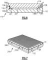
Figure 6 illustrates a sectioned view of the fixture ofFigure 4 , but with additional optional features. -
Figure 7 illustrates another example fixture in which the seal includes a band around the tool segments. - In this disclosure, like reference numerals designate like elements where appropriate and reference numerals with the addition of one-hundred or multiples thereof designate modified elements that are understood to incorporate the same features and benefits of the corresponding elements.
- Ceramic matrix composite (CMC) articles, such as but not limited to airfoils, blade outer air seals, and combustor panels for gas turbine engines, may be fabricated via infiltration of a gaseous ceramic precursor compound (or precursors thereto) into a fiber preform to form a ceramic coating on the fiber surfaces. In instances where the fiber preform is not self-supporting, a fixture may be used to support the preform in the desired geometry during processing. The fixture hinders flow of the precursor material to some regions of the fiber preform while permitting flow to other regions, thereby contributing to uneven build-up of the ceramic material and concomitant lower performance of the article. Additionally, multiple fiber preforms may be processed simultaneously in a chamber through which the gaseous precursor flows. The flow may vary by spatial location in the chamber, thereby further contributing to uneven build-ups between articles that receive more or less flow. In these regards, as will be described below, the disclosed fixture facilitates improved uniformity of the build-up of a ceramic material in a fiber preform.
-
Figure 1 illustrates anexample fixture 10 in a fully assembled state for processing, andFigure 2 illustrates an expanded view of thefixture 10. Thefixture 10 is depicted with a generic flat plate geometry, but it is to be understood that the geometry will be adapted to the geometry of the end-use article that is to be produced. Thefixture 10 includes first andsecond tool segments 12/14 and aseal 16. In general, thesegments 12/14 andseal 16 are made of materials that are inert with respect to the precursor gas used in the processing, have a maximum use temperature that exceeds the temperature at which the processing is to be conducted, and are of sufficient strength to resist breaking during processing and handling such that they can be reused. For instance, the material may be, but is not limited to, graphite (e.g., carbon graphite composites such as C-fiber/C-matrix composites). - Each of the
tool segments 12/14 has anexterior side 18a and aninterior side 18b. For contoured articles, such as airfoils or blade outer air seals, at least theinterior sides 18b may be contoured with the article geometry, such as with a cavity. Theinterior side 18b has a border mate face 20 (obscured from view on the tool segment 14). The border mate faces 20 are relatively smooth surface perimeter regions that extend inwardly from the edges of thetool segments 12/14 and serve to facilitate assembly and alignment of thetool segments 12/14. The interior sides 18b face each other such that the border mate faces 20 substantially align with each other and circumscribe a workingregion 22 for holding afiber preform 24 that is to be infiltrated with the precursor. - The working
region 22 is the volume circumscribed by the border mate faces 20 and bound by support surfaces S on the interior sides 18b of thetool segments 12/14. Thefiber preform 24 is held in the workingregion 22 and mechanically supported by the support surfaces S. The terms "interior" and "exterior" are relative to the workingregion 22 in that theexterior side 18a generally faces away from the workingregion 22 and theinterior side 18b generally faces toward the workingregion 22. - The
fiber preform 24 is shown arranged in the workingregion 22 inFigure 3 . Thefiber preform 24 is comprised ofceramic fibers 24a arranged in a fiber architecture. The ceramic fibers are formed of bundles of filaments and may include, but are not limited to, silicon carbide (SiC) fibers or carbon fibers. For instance, thepreform 24 may include multiple fiber layers or plies that are laid-up to form the geometry of the end-use article, or a portion thereof. In some instances, the fiber layers or plies are laid-up around one or more mandrels, which may remain in thepreform 24 through a portion of the processing and then be removed later on to leave one or more internal cavities in the end-use article. In general, however, theperform 24 is initially devoid of any coating or matrix material. - The
tool segments 12/14 each have an array of through-holes 26 that connect thesides 18a/18b and open through the support surfaces S to the workingregion 22. For instance, the through-holes 26 are arranged in a pattern of rows that span across the workingregion 22. The through-holes 26 permit inflow of gaseous precursor into the workingregion 22 during processing, while the pattern facilitates uniform gas distribution. - The
seal 16 circumscribes the workingregion 22. Theseal 16 blocks a gap 28 (Figure 1 ) between the border mate faces 20 to limit inflow of the gaseous precursor material through thegap 28 into the workingregion 22. In this example, theseal 16 is a separate and distinct piece from thetool segments 12/14, and is thus removable and replaceable. Theseal 16 includes first andsecond faces 16a/16b. Thefirst face 16a may be in contact with theborder mate face 20 of thefirst tool segment 12 and the second, opposedface 16b may be in contact with theborder mate face 20 of thesecond tool segment 14. The physical presence of theseal 16 in thegap 28 serves to block inflow of the gaseous precursor through thegap 28. Therefore, the only path for the gaseous precursor to reach the workingregion 22 and infiltrate thefiber preform 24 is through the through-holes 26, to thereby facilitate uniform distribution and build-up of the coating material on thefiber preform 24. Meanwhile, the blocking the gaseous precursor around the edges of thetool segments 12/14 prevents substantial build-up of a thick skin coating between the support surfaces S and the periphery of the fiber preform. - Due to tolerances or other factors, the
faces 16a/16b of theseal 16 may not contact or fully interfacially contact the border mate faces 20, leaving a slit or slits there between. The slits, however, are substantially narrower than thegap 28 such that only a small, tolerable amount of gaseous precursor is expected to flow through the slits. A slit or slits may also be present by design, to facilitate disassembly of thefixture 10 by separation of thetool segments 12/14 after processing to retrieve thecoated fiber preform 24. For example, as discussed later below, spacing thetool segments 12/14 apart may reduce bridging of the coating material. - The
tool segments 12/14 and theseal 16 also include two or more sets of pin holes 30. In the illustrated example (Figure 2 ) thefixture 10 includes four sets of pin holes 30, with one set at each of the corners of thefixture 10. Apin 32 is received through the set of pin holes 30. Thepins 32 serve to align and secure theseal 16 with respect to thetool segments 12/14. -
Figure 4 illustrates an example of anotherfixture 110, andFigure 5 illustrates an expanded view of thefixture 110. Thefixture 110 includes first andsecond tool segments 112/114 and aseal 116. In this example, rather than being a separate and distinct piece, theseal 116 is united with thefirst tool segment 112. For instance, theseal 116 and thefirst tool segment 112 are integrated as a single, homogenous piece. This may eliminate use of theholes 30 and pins 32, as theseal 116 cannot move or shift relative to thefirst tool segment 112. Alternatively, holes 30 and pins 32 may still be used to facilitate alignment of thetool segments 112/114 with each other. - The
border mate face 20 of thesecond tool segment 114 in this example is recessed from the support surface S of thesecond tool segment 114 such that the support surface S is on aplateau 134a. The support surface S of thefirst tool segment 112 is recessed from theseal 116 so as to define avalley region 134b between the recessed support surface S of thefirst tool segment 112 and the sides of theseal 116. Thevalley region 134b is generally of complementary geometry to that of theplateau 134a such that theplateau 134a fits into thevalley region 134b when thetool segments 112/114 are brought together with thefiber preform 24 sandwiched between, as shown in the sectioned view ofFigure 6 . - As further shown in
Figure 6 , thefixture 110 may further include one ormore spacers 136 that are located between theseal 116 and thesecond tool segment 114. The spacer has a spacer height (h). Thespacer 136 separates thetool segments 112/114 and establishes the height of the workingregion 22 between the support surfaces S. The height of thespacer 136 may be selected to provide a desired workingregion 22 height for afiber preform 24 of a given thickness. For instance, the thickness of thefiber preform 24 may exceed the workingregion 22 height such that thetool segments 112/114 compress thefiber preform 24. The magnitude of compression may be tailored via selection of different sizes of thespacers 136. It is to be appreciated that thespacers 136 may also be used with thefixture 10 to hold thetool segments 12/14 apart. The coating material may deposit on thefixture 10/110 and, if it bridges thetool segments 12/14/112/114, may fuse the segments together and make it difficult to disassemble the fixture to retrieve thecoated fiber preform 24. Spacing thetool segments 12/14/112/114 apart may facilitate reductions in bridging. The spacing distance, however, should generally be minimized to reduce inflow of the coating material through thegap 28 into the workingregion 22. Thespacer 136 may extend continuously around the full perimeter of thetool segments 112/114, but alternatively may be segmented and discontinuous. - As also shown, the
seal 116 may optionally include a stand-off 138 that projects toward the workingregion 22 and terminates at afree tip end 138a. Thetip end 138a contacts the side of theplateau 134a. The stand-off serves to center thesecond tool segment 114 on thefirst tool segment 112, while also minimizing the area of contact between thesegments 112/114 to reduce the chances of bridging of the coating material. For example, the stand-off 138 is a continuous ridge that extends around the full inner perimeter of theseal 116, but alternatively may be segmented and discontinuous. Alternatively, the external surfaces of the fixture 100 may be utilized for centering, in which case the stand-off 138 may be excluded. -
Figure 7 illustrates another example fixture 210. In this example, the fixture 210 is the same as thefixture 10 except that instead of theseal 16 the fixture 210 includes aseal 216. Theseal 216 is aband 240 that wraps around thetool segments 12/14. Theband 240 spans across thegap 28 between thetool segments 12/14 and thereby blocks inflow of the coating material into thegap 28. For example, theband 240 includes at least one of a fabric, a foil, or an adhesive tape. An example fabric includes, but is not limited to, a woven carbon cloth. An example foil includes, but is not limited to, a graphite foil, which is a thin, flexible strip of graphite. An example adhesive tape includes, but is not limited to, a fabric, foil, or other flexible substrate that has adhesive on one side to attach the tape to thetool segments 12/14. In further examples, theband 240 is used in combination with theseal 16 or theseal 116, to further inhibit inflow of coating material through thegap 28 into the workingregion 22. - An example method of processing a CMC article using the
fixtures 10/110/210 herein includes situating thefiber preform 24 in the workingregion 22 of any of thefixtures 10/110/210, providing theseal 16/116/216 that circumscribes the workingregion 22, and then exposing thefixture 10/110/210 with thepreform 24 to a flow of gaseous precursor. Theseal 16/116/216 blocks inflow of the gaseous precursor through thegap 28 around the edges of thetool segments 12/14/112/114. Therefore, the only path for the gaseous precursor to reach the workingregion 22 and infiltrate thepreform 24 is through the through-holes 26. The gaseous precursor may be an interface coating precursor or a matrix precursor, such as but not limited to, boron trichloride (BCl3) or methyltrichlorosilane (MTS). - Although a combination of features is shown in the illustrated examples, not all of them need to be combined to realize the benefits of various embodiments of this disclosure. In other words, a system designed according to an embodiment of this disclosure will not necessarily include all of the features shown in any one of the Figures or all of the portions schematically shown in the Figures. Moreover, selected features of one example embodiment may be combined with selected features of other example embodiments.
- The preceding description is exemplary rather than limiting in nature. Variations and modifications to the disclosed examples may become apparent to those skilled in the art that do not necessarily depart from this disclosure. The scope of legal protection given to this disclosure can only be determined by studying the following claims.
Claims (15)
- A fixture (10; 110; 210) for processing a ceramic matrix composite article, the fixture comprising:first and second tool segments (12, 14; 112, 114) each having an exterior side (18a) and an interior side (18b), the interior side (18b) having a border mate face (20), the interior side (18b) of the first tool segment (12; 112) facing the interior side (18b) of the second tool segment (14; 114) such that the border mate faces (20) align and circumscribe a working region (22) for holding a fiber preform (24) that is to be coated with a ceramic material, the first and second tool segments (12, 14; 112, 114) each having an array of through-holes (26) that open to the working region (22) to permit inflow of gaseous precursor into the working region (22); anda seal (16; 116; 216) circumscribing the working region (22), the seal (16; 116; 216) blocking a gap (28) between the border mate faces (20) to limit inflow of the gaseous coating material through the gap (28) into the working region (22).
- The fixture (10; 110; 210) as recited in claim 1, wherein the first and second tool segments (12, 14; 112, 114) and the seal (16; 116; 216) are graphite.
- The fixture (10) as recited in claim 1 or 2, wherein the seal (16) includes a first face (16a) that is in contact with the border mate face (20) of the first tool segment (12) and a second, opposed face (16b) that is in contact with the border mate face (20) of the second tool segment (14).
- The fixture (110) as recited in any preceding claim, wherein the seal (116) is united with the first tool segment (112).
- The fixture (110) as recited in claim 4, wherein the first and second tool segments (112, 114) each include a support surface (S) facing the working region (22) and through which the through-holes (26) extend, and the border mate face (20) of the second tool segment (114) is recessed from the support surface (S) of the second tool segment (114) such that the support surface (S) of the second tool segment (114)is on a plateau (134a).
- The fixture (110) as recited in claim 5, wherein the support surface (S) of the first tool segment (112) is recessed from the seal (116).
- The fixture (110) as recited in claim 5 or 6, further comprising one or more spacers (136) between the seal (116) and the second tool segment (114) , the one or more spacers (136) having a spacer height (h) that establishes a height of the working region (22) between the support surfaces (S).
- The fixture (110) as recited in any of claims 5 to 7, wherein the seal (116) includes a stand-off (138) projecting therefrom to a free tip (138a), the free tip (138a) contacting a side of the plateau (134a), optionally, wherein the stand-off (138) is a ridge that circumscribes the plateau (134a).
- The fixture (10; 110) as recited in any preceding claim, wherein the first and second tool segments (12, 14; 112, 114) and the seal (16; 116) include two or more sets of pin holes (30) that are aligned, and two or more pins (32) receivable in the two or more sets of pin holes (30), the pins (32) aligning and securing the seal (16; 116) with respect to the first and second tool segments (12, 14; 112, 114).
- The fixture (210) as recited in any preceding claim, wherein the seal (216) is a band (240) wrapped around the first and second tool segments (12, 14).
- A fixture (210) for processing a ceramic matrix composite article, the fixture (210) comprising:
first and second tool segments (12, 14) each having an exterior side (18a) and an interior side (18b), the interior side (18b) having a border mate face (20), the interior side (18b) of the first tool segment (12) facing the interior side (18b) of the second tool segment (14) such that the border mate face (20) of the first tool segment (12) aligns with the border mate face (20) of the second tool segment (14), the border mate faces (20) align and circumscribe a working region (22) for holding a fiber preform (24) that is to be coated with a ceramic material, the first and second tool segments (12, 14) each having an array of through-holes (16) that open to the working region (22) to permit inflow of gaseous precursor from the exterior side (18) into the working region (22); and
a band (240) wrapped around the first and second tool segments (12, 14), the band (240) sealing a gap (28) between the border mate faces (20) to limit inflow of the gaseous coating material through the gap (28) into the working region (22). - A method for processing a ceramic matrix composite article, the method comprising:providing a fixture (10; 110; 210) that includes first and second tool segments (12, 14; 112, 114) that each have an exterior side (18a) and an interior side (18b), the interior side has a border mate face (20), the interior side (18b) of the first tool segment (12; 112) faces the interior side (18b) of the second tool segment (14; 114) such that the border mate faces (20) align and circumscribe a working region (22), the first and second tool segments (12, 14; 112, 114) each having an array of through-holes (26) that open to the working region (22);situating a fiber preform (24) in the working region (22);providing a seal (16; 116; 216) that circumscribes the working region (22); andexposing the fixture (10; 110; 210) with the fiber preform (24) to a flow of gaseous precursor, the gaseous precursor flowing into the working region (22) and infiltrating the fiber preform (24) to deposit a coating on the fiber preform (24), wherein the seal (16; 116; 216) blocks a gap (28) between the border mate faces (20) to limit inflow of the gaseous precursor through the gap (28) into the working region (22) so that the gaseous precursor must flow through the through-holes (26) to reach the working region (22).
- The method as recited in claim 12, wherein the providing of the seal (16; 116) includes arranging the seal (16; 116) between the first and second tool segments (12, 14; 112, 114).
- The method as recited in claim 12, wherein the providing of the seal (216) includes wrapping a band (240) around the first and second tool segments (12, 14).
- The method as recited in claim 14 or the fixture of claims 10 or 11, wherein the band (240) includes at least one of a fabric, a foil, or an adhesive tape.
Applications Claiming Priority (1)
| Application Number | Priority Date | Filing Date | Title |
|---|---|---|---|
| US18/071,078 US12311578B2 (en) | 2022-11-29 | 2022-11-29 | Edge-sealed fixture for processing CMC |
Publications (1)
| Publication Number | Publication Date |
|---|---|
| EP4379089A1 true EP4379089A1 (en) | 2024-06-05 |
Family
ID=88923814
Family Applications (1)
| Application Number | Title | Priority Date | Filing Date |
|---|---|---|---|
| EP23211579.0A Pending EP4379089A1 (en) | 2022-11-29 | 2023-11-22 | Edge-sealed fixture for processing cmc |
Country Status (2)
| Country | Link |
|---|---|
| US (2) | US12311578B2 (en) |
| EP (1) | EP4379089A1 (en) |
Citations (4)
| Publication number | Priority date | Publication date | Assignee | Title |
|---|---|---|---|---|
| FR3021671A1 (en) * | 2014-05-28 | 2015-12-04 | Herakles | CONFORMER FOR GAS PHASE CONSOLIDATION AND / OR DENSIFICATION OF A FIBROUS PREFORM |
| US20200061868A1 (en) * | 2016-12-07 | 2020-02-27 | Safran Ceramics | Shaping equipment and facility for gas-phase chemical infiltration of fibrous preforms |
| WO2021165599A1 (en) * | 2020-02-19 | 2021-08-26 | Safran Ceramics | Consolidation method using gas phase infiltration |
| US11472747B2 (en) * | 2019-10-08 | 2022-10-18 | Rolls-Royce High Temperature Composites Inc. | Assembly for chemical vapor infiltration of a fiber preform and method of infiltrating a fiber preform |
Family Cites Families (8)
| Publication number | Priority date | Publication date | Assignee | Title |
|---|---|---|---|---|
| USRE34825E (en) | 1981-06-15 | 1995-01-10 | Minnesota Mining And Manufacturing Company | Composite article and method of making same |
| US8875931B2 (en) | 2010-11-19 | 2014-11-04 | The Boeing Company | Composite sandwich shell edge joint |
| FR2993555B1 (en) | 2012-07-19 | 2015-02-20 | Herakles | INSTALLATION OF HEAVY DUTY CHEMICAL INFILTRATION WITH HIGH LOAD CAPACITY |
| CA2901835A1 (en) * | 2013-03-04 | 2014-10-02 | Rolls-Royce North American Technologies, Inc. | Compartmentalization of cooling air flow in a structure comprising a cmc component |
| US10794205B2 (en) | 2017-02-27 | 2020-10-06 | Rolls-Royce North American Technologies Inc. | Ceramic seal component for gas turbine engine and process of making the same |
| US10906842B2 (en) | 2018-10-18 | 2021-02-02 | Rolls-Royce High Temperature Composites Inc. | Method of processing a ceramic matrix composite (CMC) component |
| US11046620B2 (en) | 2018-10-18 | 2021-06-29 | Rolls-Royce Corporation | Method of processing a ceramic matrix composite (CMC) component |
| US20230242451A1 (en) * | 2022-02-03 | 2023-08-03 | General Electric Company | Tools and methods for their formation and use |
-
2022
- 2022-11-29 US US18/071,078 patent/US12311578B2/en active Active
-
2023
- 2023-11-22 EP EP23211579.0A patent/EP4379089A1/en active Pending
-
2025
- 2025-04-30 US US19/194,400 patent/US20250269560A1/en active Pending
Patent Citations (4)
| Publication number | Priority date | Publication date | Assignee | Title |
|---|---|---|---|---|
| FR3021671A1 (en) * | 2014-05-28 | 2015-12-04 | Herakles | CONFORMER FOR GAS PHASE CONSOLIDATION AND / OR DENSIFICATION OF A FIBROUS PREFORM |
| US20200061868A1 (en) * | 2016-12-07 | 2020-02-27 | Safran Ceramics | Shaping equipment and facility for gas-phase chemical infiltration of fibrous preforms |
| US11472747B2 (en) * | 2019-10-08 | 2022-10-18 | Rolls-Royce High Temperature Composites Inc. | Assembly for chemical vapor infiltration of a fiber preform and method of infiltrating a fiber preform |
| WO2021165599A1 (en) * | 2020-02-19 | 2021-08-26 | Safran Ceramics | Consolidation method using gas phase infiltration |
Also Published As
| Publication number | Publication date |
|---|---|
| US20240173893A1 (en) | 2024-05-30 |
| US20250269560A1 (en) | 2025-08-28 |
| US12311578B2 (en) | 2025-05-27 |
Similar Documents
| Publication | Publication Date | Title |
|---|---|---|
| US11441436B2 (en) | Flow path assemblies for gas turbine engines and assembly methods therefore | |
| US7255535B2 (en) | Cooling systems for stacked laminate CMC vane | |
| US11466580B2 (en) | CMC nozzle with interlocking mechanical joint and fabrication | |
| US11459908B2 (en) | CMC component including directionally controllable CMC insert and method of fabrication | |
| US7223465B2 (en) | SiC/SiC composites incorporating uncoated fibers to improve interlaminar strength | |
| EP2784269A1 (en) | Wall section for the working gas annulus of a gas turbine engine, corresponding shroud ring and gas turbine engine | |
| US7247212B2 (en) | Orthogonal weaving for complex shape preforms | |
| US20140127457A1 (en) | Ceramic matrix composite component forming method | |
| CA3102096C (en) | Ceramic matrix composite component and method of producing a ceramic matrix composite component | |
| EP3650424B1 (en) | Accelerated cvi densification of cmc through infiltration | |
| CN109414888B (en) | Axisymmetric component and method for forming same | |
| EP3572625B1 (en) | Joint for a shroud platform in ceramic | |
| EP4379089A1 (en) | Edge-sealed fixture for processing cmc | |
| EP4379090A1 (en) | Fixture with grooves for processing cmc article | |
| WO2020018090A1 (en) | Hybrid components having an intermediate ceramic fiber material | |
| EP3982046B1 (en) | Combustor liner and method of operating same | |
| WO2020023021A1 (en) | Ceramic matrix composite materials having reduced anisotropic sintering shrinkage |
Legal Events
| Date | Code | Title | Description |
|---|---|---|---|
| PUAI | Public reference made under article 153(3) epc to a published international application that has entered the european phase |
Free format text: ORIGINAL CODE: 0009012 |
|
| STAA | Information on the status of an ep patent application or granted ep patent |
Free format text: STATUS: THE APPLICATION HAS BEEN PUBLISHED |
|
| AK | Designated contracting states |
Kind code of ref document: A1 Designated state(s): AL AT BE BG CH CY CZ DE DK EE ES FI FR GB GR HR HU IE IS IT LI LT LU LV MC ME MK MT NL NO PL PT RO RS SE SI SK SM TR |
|
| STAA | Information on the status of an ep patent application or granted ep patent |
Free format text: STATUS: REQUEST FOR EXAMINATION WAS MADE |
|
| 17P | Request for examination filed |
Effective date: 20241203 |
|
| RBV | Designated contracting states (corrected) |
Designated state(s): AL AT BE BG CH CY CZ DE DK EE ES FI FR GB GR HR HU IE IS IT LI LT LU LV MC ME MK MT NL NO PL PT RO RS SE SI SK SM TR |