EP4378827A1 - Wing for an aircraft - Google Patents
Wing for an aircraft Download PDFInfo
- Publication number
- EP4378827A1 EP4378827A1 EP22210458.0A EP22210458A EP4378827A1 EP 4378827 A1 EP4378827 A1 EP 4378827A1 EP 22210458 A EP22210458 A EP 22210458A EP 4378827 A1 EP4378827 A1 EP 4378827A1
- Authority
- EP
- European Patent Office
- Prior art keywords
- wing
- flap
- main wing
- panel
- gap
- Prior art date
- Legal status (The legal status is an assumption and is not a legal conclusion. Google has not performed a legal analysis and makes no representation as to the accuracy of the status listed.)
- Pending
Links
Images


Classifications
-
- B—PERFORMING OPERATIONS; TRANSPORTING
- B64—AIRCRAFT; AVIATION; COSMONAUTICS
- B64C—AEROPLANES; HELICOPTERS
- B64C9/00—Adjustable control surfaces or members, e.g. rudders
- B64C9/02—Mounting or supporting thereof
-
- B—PERFORMING OPERATIONS; TRANSPORTING
- B64—AIRCRAFT; AVIATION; COSMONAUTICS
- B64C—AEROPLANES; HELICOPTERS
- B64C9/00—Adjustable control surfaces or members, e.g. rudders
- B64C9/14—Adjustable control surfaces or members, e.g. rudders forming slots
- B64C9/16—Adjustable control surfaces or members, e.g. rudders forming slots at the rear of the wing
-
- B—PERFORMING OPERATIONS; TRANSPORTING
- B64—AIRCRAFT; AVIATION; COSMONAUTICS
- B64C—AEROPLANES; HELICOPTERS
- B64C3/00—Wings
- B64C3/36—Structures adapted to reduce effects of aerodynamic or other external heating
-
- B—PERFORMING OPERATIONS; TRANSPORTING
- B64—AIRCRAFT; AVIATION; COSMONAUTICS
- B64C—AEROPLANES; HELICOPTERS
- B64C3/00—Wings
- B64C3/38—Adjustment of complete wings or parts thereof
-
- B—PERFORMING OPERATIONS; TRANSPORTING
- B64—AIRCRAFT; AVIATION; COSMONAUTICS
- B64C—AEROPLANES; HELICOPTERS
- B64C3/00—Wings
- B64C3/38—Adjustment of complete wings or parts thereof
- B64C3/44—Varying camber
- B64C3/50—Varying camber by leading or trailing edge flaps
-
- B—PERFORMING OPERATIONS; TRANSPORTING
- B64—AIRCRAFT; AVIATION; COSMONAUTICS
- B64C—AEROPLANES; HELICOPTERS
- B64C3/00—Wings
- B64C3/38—Adjustment of complete wings or parts thereof
- B64C3/54—Varying in area
-
- B—PERFORMING OPERATIONS; TRANSPORTING
- B64—AIRCRAFT; AVIATION; COSMONAUTICS
- B64C—AEROPLANES; HELICOPTERS
- B64C9/00—Adjustable control surfaces or members, e.g. rudders
- B64C9/14—Adjustable control surfaces or members, e.g. rudders forming slots
- B64C9/16—Adjustable control surfaces or members, e.g. rudders forming slots at the rear of the wing
- B64C9/18—Adjustable control surfaces or members, e.g. rudders forming slots at the rear of the wing by single flaps
-
- B—PERFORMING OPERATIONS; TRANSPORTING
- B64—AIRCRAFT; AVIATION; COSMONAUTICS
- B64C—AEROPLANES; HELICOPTERS
- B64C9/00—Adjustable control surfaces or members, e.g. rudders
- B64C9/14—Adjustable control surfaces or members, e.g. rudders forming slots
- B64C2009/143—Adjustable control surfaces or members, e.g. rudders forming slots comprising independently adjustable elements for closing or opening the slot between the main wing and leading or trailing edge flaps
Definitions
- the present invention relates to a wing for an aircraft. Further aspects of the invention relate to a gap closing device for such a wing, and to an aircraft comprising such a wing and/or comprising such a gap closing device.
- the wing comprises a main wing and a trailing edge high lift assembly.
- the trailing edge high lift assembly is movably arranged at a trailing edge of the main wing and comprises a flap and a connection assembly.
- the connection assembly movably mounts the flap to the main wing, such that the flap is movable relative to the main wing between at least one retracted position with a reduced chord length and/or curvature of the wing, and at least one extended position with an extended chord length and/or curvature of the wing.
- the connection assembly preferably comprises an actuator unit, e.g. including a rotary motor or a linear motor, for moving the flap between the at least one retracted position and the at least one extended position.
- a gap is present between a lower rear panel, preferably skin panel, of the main wing and a leading edge section of the flap to allow an air flow to pass between the flap and the main wing, in order to energize the air flow along the top surface of the flap.
- the gap is closed or minimized, so that an air flow between the flap and the main wing is inhibited or at least minimized, in order to reduce drag.
- Similar wings are known in the art.
- Some known wings comprise a trailing edge high lift assembly having a flap that is movable relative to the main wing in a rotational manner or in a combined linear and rotational manner, between one retracted position and at least one extended position.
- Such trailing edge high lift assemblies are designed to be deployed, i.e. moved to the at least one extended position, during take-off and landing of an aircraft to increase lift and reduce minimum air speed by increasing wing area, curvature, and angle of attack, and to be retracted during cruise flight when air speed is high to reduce drag.
- a morphing wing that might adjust wing area, curvature, and angle of attack during the entire flight, e.g. as a "real-time" response to gust or to optimise lift, drag and structural loading during the flight.
- the two-part flap comprising leading edge part and trailing edge part which can be moved relative to one another as required, and/or by adding further setting positions of the flap.
- aerodynamic performance of the wing should not be negatively affected in any of the settings of the flap.
- the object of the invention is to provide a wing that might be used as a morphing wing capable of adjusting wing area, curvature, and angle of attack during the entire flight, while having optimized aerodynamic performance throughout all flap settings.
- the flap is movable between at least one extended position, a first retracted position, and a second retracted position.
- the first retracted position might preferably be a neutral retracted position, preferably for cruise flight under normal conditions.
- the second retracted position which might preferably be a negative retracted position
- the flap is moved beyond the first retracted position in a forward direction further towards a leading edge of the main wing, thereby preferably further reducing the chord length of the wing compared to the first retracted position.
- the wing comprises a gap closing device configured to close or minimize the gap in both the first retracted position and the second retracted position of the flap, and to open the gap in the at least one extended position of the flap.
- the wing might comprise multiple gap closing devices formed as described above and arranged next to each other in a span direction of the wing.
- the gap closing device is a passive device, i.e. it does not include an actuator and/or is movable without being directly actuated. This relates to a very simple and lightweight form of the gap closing device.
- the gap closing device is movably mounted to the main wing. In such a way, it can adjust its position to close or open the gap as required.
- the gap closing device is movable in one direction, in particular the forward direction, by contact with the flap when the flap is moved relative to the main wing, preferably between the first retracted position and the second retracted position, and is movable in the opposite direction, in particular a rearward direction, preferably between the second retracted position and the first retracted position, preferably by a biasing member, such as a spring.
- the gap closing device may be pushed by the flap from the first retracted position to the second retracted position, and may be reversed from the second retracted position to the first retracted position by the biasing member. In such a way, a very simple efficient, and reliable passive gap closing device is formed.
- the gap closing device comprises a closing panel, preferably in the form of a skin panel, forming an extension of the lower rear panel of the main wing in the rearward direction, i.e. in the direction to the flap.
- the closing panel is movable relative to the lower rear panel of the main wing between an elongated position, where the closing panel forms a greater or maximum extension of the lower rear panel of the main wing, and a shortened position, where the closing panel forms a smaller or minimum extension of the lower rear panel of the main wing.
- the gap closing device is configured such that when the flap is in the at least one extended position and in the first retracted position the closing panel is in the elongated position, while when the flap is in the second retracted position the closing panel is in the shortened position. In such a way, a very simple efficient, and reliable passive gap closing device is formed.
- the gap closing device is configured such that when the closing panel is moved from the elongated position to the shortened position the closing panel is moved behind the lower rear panel of the main wing, such that a part of the closing panel overlaps with the lower rear panel of the main wing. In such a way, the gap can be efficiently closed throughout the movement range of the closing panel and a possibly smooth transition between the closing panel and the lower rear panel of the main wing is enabled.
- the closing panel at its forward end has a step, preferably with a chamfered edge, such that in the elongated position the step may engage a rear end of the lower rear panel of the main wing and there is preferably a smooth transition from the outer surface of the closing panel to the outer surface of the lower rear panel of the main wing, while when moved to the shortened position the step is moved beyond the rear end of the lower rear panel of the main wing and behind the lower rear panel of the main wing.
- the rear end of the lower rear panel of the main wing is also chamfered to correspond to and possibly slide along the chamfered edge of the step, when the closing panel is moved from the elongated to the shortened position.
- the gap closing device comprises a linkage movably mounting the closing panel to the main wing.
- a linkage represents a very simple, efficient and reliable way of movably mounting the closing panel to the main wing.
- multiple linkages are provided, preferably arranged subsequently in the span direction, together mounting the closing panel to the main wing.
- the linkage comprises a first link and a second link.
- the first link is rotatably mounted to the main wing, preferably at its one end, and is rotatably mounted to the closing panel, preferably at its opposite end.
- the second link is rotatably mounted to the main wing, preferably at its one end, and is rotatably mounted to the closing panel, preferably at its opposite end, at a position spaced apart from the first link.
- the rotatable joints between the first and second link, respectively, and the closing panel on the one hand, and between the first and second link, respectively, and the main wing on the other hand preferably have parallel axes of rotation and might also be realized as fixed body joints.
- the linkage is formed as a four-bar-linkage which relates to a very simple, efficient and reliable way of movably mounting the closing panel to the main wing.
- the closing panel comprises a catch element configured for being contacted by the flap when the flap is moved between the first retracted position and the second retracted position, so that by contact with the catch the flap may push the closing panel from the elongated position to the shortened position when the flap is moved from the first retracted position to the second retracted position.
- the catch element might be formed as e.g. a rod, panel, or other projection extending away from the inner surface of the closing panel.
- the catch element might also comprise a flap contact roller mounted directly or indirectly to the closing panel, e.g. to a rod of the catch element, and configured for rolling contact with the leading edge section of the flap.
- the gap closing device comprises at least one biasing member configured to bias the closing panel towards the flap and in particular the catch element in contact with the flap, i.e. towards the elongated position.
- the biasing member might be e.g. a linear spring coupled between the main wing at one end and the closing panel, the first link and/or the second link at the other end, or might be a torsion spring coupled between the main wing and/or the closing panel at one end and the first link and/or the second link at the other end.
- the torsion spring might also be realized as a fixed body joint.
- Such a biasing member forms a very simple, efficient and reliable means to passively move the closing panel from the shortened position back to the elongated position.
- the gap closing device comprises at least one stop member configured to limit movement of the closing panel beyond the elongated position.
- the stop member is configured such that movement of the closing panel towards the flap is stopped at the elongated position.
- the stop member is preferably configured to be contacted by the closing panel or by the first or second link, and is preferably attached to the main wing. Such a stop member allows to stop movement of the closing panel precisely at the intended position, i.e. at the elongated position.
- a further aspect of the present invention relates to a gap closing device for the wing according to any of the embodiments explained above.
- the gap closing device comprises a closing panel and a linkage.
- the closing panel is configured to form an extension of the lower rear panel of the main wing in a rearward direction.
- the linkage is configured for movably mounting the closing panel to the main wing.
- a further aspect of the present invention relates to an aircraft comprising the wing according to any of the embodiments explained above, and/or comprising the gap closing device according to any of the embodiments explained above.
- the features and effects explained above in connection with the wing and the gap closing device apply vis-à-vis also to the aircraft.
- Fig. 1 shows an exemplary aircraft 1 according to an embodiment of the present invention.
- the aircraft 1 comprises a wing 3 including a main wing 5 mounted to a fuselage 7, and a trailing edge high lift assembly 9 including a flap 11 movably mounted to the main wing 5.
- Figs. 2 to 5 illustrate an embodiment of the wing 3 of the aircraft 1 shown in Fig. 1 .
- the wing 3 comprises a main wing 5 and a trailing edge high lift assembly 9.
- the trailing edge high lift assembly 9 is movably arranged at a trailing edge of the main wing 5 and comprises a flap 11 and a connection assembly (not shown).
- the connection assembly movably mounts the flap 11 to the main wing 5, such that the flap 11 is movable between first and second retracted positions 12, 14 with a reduced chord length and curvature of the wing 3, and an extended position 15 with an extended chord length and curvature of the wing 3.
- a gap 16 is present between a lower rear panel 17 of the main wing 5 and a leading edge section 19 of the flap 11 to allow an air flow 21 to pass between the flap 11 and the main wing 5, in order to energize the air flow along the top surface of the flap 11.
- the gap 16 is closed or minimized, so that an air flow 21 between the flap 11 and the main wing 5 is inhibited or at least minimized, in order to reduce drag.
- the flap 11 is movable between an extended position 15, as shown in Fig. 2 , a first retracted position 12, as shown in Fig. 3 , and a second retracted position 14, as shown in Fig. 4 .
- the first retracted position 12 in the present embodiment is a neutral retracted position intended for cruise flight under normal conditions.
- the second retracted position 14, which in the present embodiment is a negative retracted position the flap 11 is moved beyond the first retracted position 12 in a forward direction 13 further towards a leading edge of the main wing 5, thereby further reducing the chord length of the wing 3 compared to the first retracted position 12.
- the wing 3 comprises a gap closing device 23 configured to close or minimize the gap 16 in both the first retracted position 12 (see Fig. 3 ) and the second retracted position 14 (see Fig. 4 ) of the flap 11, and to open the gap 16 in the at least one extended position 15 (see Fig. 2 ) of the flap 11.
- the gap closing device 23 is a passive device and does not include an actuator.
- the gap closing device 23 comprises a closing panel 25 forming an extension of the lower rear panel 17 of the main wing 5 in the rearward direction 27.
- the closing panel 25 is movable relative to the lower rear panel 17 of the main wing 5 between an elongated position 29 (see Fig. 2 and 3 ), where the closing panel 25 forms a maximum extension of the lower rear panel 17 of the main wing 5, and a shortened position 31 (see Fig. 4 ), where the closing panel 25 forms a minimum extension of the lower rear panel 17 of the main wing 5.
- the gap closing device 23 is configured such that when the flap 11 is in the extended position 15 and in the first retracted position 12 the closing panel 25 is in the elongated position 29, while when the flap 11 is in the second retracted position 14 the closing panel 25 is in the shortened position 31.
- the gap closing device 23 is configured such that when the closing panel 25 is moved from the elongated position 29 to the shortened position 31 the closing panel 25 is moved behind the lower rear panel 17 of the main wing 5, such that a part of the closing panel 25 overlaps with the lower rear panel 17 of the main wing 5.
- the closing panel 25 at its forward end has a step 33 with a chamfered edge 35, as shown in Fig.
- the step 33 may engage a rear end 37 of the lower rear panel 17 of the main wing 5 and there is a smooth transition from the outer surface of the closing panel 25 to the outer surface of the lower rear panel 17 of the main wing 5, while when moved to the shortened position 31 the step 33 is moved beyond the rear end 37 of the lower rear panel 17 of the main wing 5 and behind the lower rear panel 17 of the main wing 5.
- the rear end 37 of the lower rear panel 17 of the main wing 5 is also chamfered to correspond to and slide along the chamfered edge 35 of the step 33, when the closing panel 25 is moved from the elongated position 29 to the shortened position 31, see Fig. 5 .
- the gap closing device 23 comprises a linkage 39 movably mounting the closing panel 25 to the main wing 5.
- the linkage 39 comprises a first link 41 and a second link 43.
- the first link 41 is rotatably mounted to the main wing 5 and is rotatably mounted to the closing panel 25.
- the second link 43 is rotatably mounted to the main wing 5 and is rotatably mounted to the closing panel 25 at a position spaced apart from the first link 41.
- the rotatable joints 45 between the first and second links 41 ,43 and the closing panel 25 on the one hand, and between the first and second links 41, 43 and the main wing 5 on the other hand, preferably have parallel axes of rotation and might also be realized as fixed body joints.
- the closing panel 25 comprises a catch element 45 configured for being contacted by the flap 11 when the flap 11 is moved between the first retracted position 12 and the second retracted position 14, so that by contact with the catch element 45 the flap 11 may push the closing panel 25 from the elongated position 29 to the shortened position 31 when the flap 11 is moved from the first retracted position 12 to the second retracted position 14.
- the catch element 45 is formed as a rod, panel, or other projection extending away from the inner surface of the closing panel 25.
- the catch element 45 might comprise a flap contact roller (not shown) mounted directly or indirectly to the closing panel 25 and configured for rolling contact with the leading edge section of the flap 11.
- the gap closing device 23 comprises a biasing member 47 configured to bias the closing panel 25 towards the flap 11, and the catch element 45 in contact with the leading edge section of the flap 11, i.e. towards the elongated position 29.
- the biasing member 47 in the present embodiment is a linear spring coupled between the main wing 5 and the first link 41.
- the gap closing device 23 further comprises a stop member 49 configured to limit movement of the closing panel 25 beyond the elongated position 29.
- the stop member 49 is configured such that movement of the closing panel 25 towards the flap 11 is stopped at the elongated position 29.
- the stop member 49 in the present embodiment is configured to be contacted by the second link 43, and is attached to the main wing 5.
- a wing 3 By such a wing 3 according to the invention introducing a second retracted position 14 with reduced chord length, drag and structural loading can be further reduced and flight parameters can be optimized, while at the same time the gap 16 between the lower rear panel 17 of the main wing 5 and the leading edge section 19 of the flap 11 can be kept closed by the gap closing device 23 in both the first retracted position 12 and the second retracted position 14, and can be kept open for air to pass through in the extended position 15, in order to achieve optimized aerodynamic performance throughout all positions of the flap 11.
Landscapes
- Engineering & Computer Science (AREA)
- Aviation & Aerospace Engineering (AREA)
- Mechanical Engineering (AREA)
- Physics & Mathematics (AREA)
- Fluid Mechanics (AREA)
- Specific Sealing Or Ventilating Devices For Doors And Windows (AREA)
Abstract
Description
- The present invention relates to a wing for an aircraft. Further aspects of the invention relate to a gap closing device for such a wing, and to an aircraft comprising such a wing and/or comprising such a gap closing device.
- The wing comprises a main wing and a trailing edge high lift assembly. The trailing edge high lift assembly is movably arranged at a trailing edge of the main wing and comprises a flap and a connection assembly. The connection assembly movably mounts the flap to the main wing, such that the flap is movable relative to the main wing between at least one retracted position with a reduced chord length and/or curvature of the wing, and at least one extended position with an extended chord length and/or curvature of the wing. The connection assembly preferably comprises an actuator unit, e.g. including a rotary motor or a linear motor, for moving the flap between the at least one retracted position and the at least one extended position.
- In the at least one extended position a gap is present between a lower rear panel, preferably skin panel, of the main wing and a leading edge section of the flap to allow an air flow to pass between the flap and the main wing, in order to energize the air flow along the top surface of the flap. In the at least one retracted position the gap is closed or minimized, so that an air flow between the flap and the main wing is inhibited or at least minimized, in order to reduce drag.
- Similar wings are known in the art. Some known wings comprise a trailing edge high lift assembly having a flap that is movable relative to the main wing in a rotational manner or in a combined linear and rotational manner, between one retracted position and at least one extended position. Such trailing edge high lift assemblies are designed to be deployed, i.e. moved to the at least one extended position, during take-off and landing of an aircraft to increase lift and reduce minimum air speed by increasing wing area, curvature, and angle of attack, and to be retracted during cruise flight when air speed is high to reduce drag.
- More recent investigations have shown that it might be advantageous to have a morphing wing that might adjust wing area, curvature, and angle of attack during the entire flight, e.g. as a "real-time" response to gust or to optimise lift, drag and structural loading during the flight.
- This can be achieved e.g. by the two-part flap comprising leading edge part and trailing edge part which can be moved relative to one another as required, and/or by adding further setting positions of the flap. However, aerodynamic performance of the wing should not be negatively affected in any of the settings of the flap.
- The object of the invention is to provide a wing that might be used as a morphing wing capable of adjusting wing area, curvature, and angle of attack during the entire flight, while having optimized aerodynamic performance throughout all flap settings.
- This object is achieved in that the flap is movable between at least one extended position, a first retracted position, and a second retracted position. The first retracted position might preferably be a neutral retracted position, preferably for cruise flight under normal conditions. In the second retracted position, which might preferably be a negative retracted position, the flap is moved beyond the first retracted position in a forward direction further towards a leading edge of the main wing, thereby preferably further reducing the chord length of the wing compared to the first retracted position. Further, the wing comprises a gap closing device configured to close or minimize the gap in both the first retracted position and the second retracted position of the flap, and to open the gap in the at least one extended position of the flap.
- By such a wing introducing a second retracted position with reduced chord length, drag and structural loading can be further reduced and flight parameters can be optimized, while at the same time the gap between the lower rear panel of the main wing and the leading edge section of the flap can be kept closed by the gap closing device in both the first retracted position and the second retracted position, and can be kept open for air to pass through in the one or more extended position, in order to achieve optimized aerodynamic performance throughout all positions of the flap.
- The wing might comprise multiple gap closing devices formed as described above and arranged next to each other in a span direction of the wing.
- According to a preferred embodiment, the gap closing device is a passive device, i.e. it does not include an actuator and/or is movable without being directly actuated. This relates to a very simple and lightweight form of the gap closing device.
- According to a further preferred embodiment, the gap closing device is movably mounted to the main wing. In such a way, it can adjust its position to close or open the gap as required.
- According to a further preferred embodiment, the gap closing device is movable in one direction, in particular the forward direction, by contact with the flap when the flap is moved relative to the main wing, preferably between the first retracted position and the second retracted position, and is movable in the opposite direction, in particular a rearward direction, preferably between the second retracted position and the first retracted position, preferably by a biasing member, such as a spring. In other words, the gap closing device may be pushed by the flap from the first retracted position to the second retracted position, and may be reversed from the second retracted position to the first retracted position by the biasing member. In such a way, a very simple efficient, and reliable passive gap closing device is formed.
- According to a further preferred embodiment, the gap closing device comprises a closing panel, preferably in the form of a skin panel, forming an extension of the lower rear panel of the main wing in the rearward direction, i.e. in the direction to the flap. The closing panel is movable relative to the lower rear panel of the main wing between an elongated position, where the closing panel forms a greater or maximum extension of the lower rear panel of the main wing, and a shortened position, where the closing panel forms a smaller or minimum extension of the lower rear panel of the main wing. By such a movable closing panel a very simple and efficient gap closing device is formed. It is also possible that multiple closing panels are provided next to each other in the span direction.
- In particular, it is preferred that the gap closing device is configured such that when the flap is in the at least one extended position and in the first retracted position the closing panel is in the elongated position, while when the flap is in the second retracted position the closing panel is in the shortened position. In such a way, a very simple efficient, and reliable passive gap closing device is formed.
- It is further preferred that the gap closing device is configured such that when the closing panel is moved from the elongated position to the shortened position the closing panel is moved behind the lower rear panel of the main wing, such that a part of the closing panel overlaps with the lower rear panel of the main wing. In such a way, the gap can be efficiently closed throughout the movement range of the closing panel and a possibly smooth transition between the closing panel and the lower rear panel of the main wing is enabled.
- In particular, it is preferred that the closing panel at its forward end has a step, preferably with a chamfered edge, such that in the elongated position the step may engage a rear end of the lower rear panel of the main wing and there is preferably a smooth transition from the outer surface of the closing panel to the outer surface of the lower rear panel of the main wing, while when moved to the shortened position the step is moved beyond the rear end of the lower rear panel of the main wing and behind the lower rear panel of the main wing. Preferably, the rear end of the lower rear panel of the main wing is also chamfered to correspond to and possibly slide along the chamfered edge of the step, when the closing panel is moved from the elongated to the shortened position. By such a step a possibly smooth transition between the closing panel and the lower rear panel of the main wing is enabled throughout the movement range of the closing panel.
- According to a preferred embodiment, the gap closing device comprises a linkage movably mounting the closing panel to the main wing. Such a linkage represents a very simple, efficient and reliable way of movably mounting the closing panel to the main wing. Preferably, multiple linkages are provided, preferably arranged subsequently in the span direction, together mounting the closing panel to the main wing.
- In particular, it is preferred that the linkage comprises a first link and a second link. The first link is rotatably mounted to the main wing, preferably at its one end, and is rotatably mounted to the closing panel, preferably at its opposite end. The second link is rotatably mounted to the main wing, preferably at its one end, and is rotatably mounted to the closing panel, preferably at its opposite end, at a position spaced apart from the first link. The rotatable joints between the first and second link, respectively, and the closing panel on the one hand, and between the first and second link, respectively, and the main wing on the other hand, preferably have parallel axes of rotation and might also be realized as fixed body joints. In such a way, the linkage is formed as a four-bar-linkage which relates to a very simple, efficient and reliable way of movably mounting the closing panel to the main wing.
- According to a preferred embodiment, the closing panel comprises a catch element configured for being contacted by the flap when the flap is moved between the first retracted position and the second retracted position, so that by contact with the catch the flap may push the closing panel from the elongated position to the shortened position when the flap is moved from the first retracted position to the second retracted position. The catch element might be formed as e.g. a rod, panel, or other projection extending away from the inner surface of the closing panel. The catch element might also comprise a flap contact roller mounted directly or indirectly to the closing panel, e.g. to a rod of the catch element, and configured for rolling contact with the leading edge section of the flap. By such a catch element a defined and reliable contact between the leading edge section of the flap and the closing panel is ensured when the flap is moved from the first retracted position to the second retracted position, thereby pushing the closing panel from the elongated position to the shortened position.
- According to a preferred embodiment, the gap closing device comprises at least one biasing member configured to bias the closing panel towards the flap and in particular the catch element in contact with the flap, i.e. towards the elongated position. The biasing member might be e.g. a linear spring coupled between the main wing at one end and the closing panel, the first link and/or the second link at the other end, or might be a torsion spring coupled between the main wing and/or the closing panel at one end and the first link and/or the second link at the other end. The torsion spring might also be realized as a fixed body joint. Such a biasing member forms a very simple, efficient and reliable means to passively move the closing panel from the shortened position back to the elongated position.
- According to a preferred embodiment, the gap closing device comprises at least one stop member configured to limit movement of the closing panel beyond the elongated position. I.e., the stop member is configured such that movement of the closing panel towards the flap is stopped at the elongated position. The stop member is preferably configured to be contacted by the closing panel or by the first or second link, and is preferably attached to the main wing. Such a stop member allows to stop movement of the closing panel precisely at the intended position, i.e. at the elongated position.
- A further aspect of the present invention relates to a gap closing device for the wing according to any of the embodiments explained above. The gap closing device comprises a closing panel and a linkage. The closing panel is configured to form an extension of the lower rear panel of the main wing in a rearward direction. The linkage is configured for movably mounting the closing panel to the main wing. The features and effects explained above in connection with the wing apply vis-à-vis also to the gap closing device.
- A further aspect of the present invention relates to an aircraft comprising the wing according to any of the embodiments explained above, and/or comprising the gap closing device according to any of the embodiments explained above. The features and effects explained above in connection with the wing and the gap closing device apply vis-à-vis also to the aircraft.
- Hereinafter, a preferred embodiment of the present invention is described in more detail by means of a drawing. The drawing shows in
- Fig. 1
- a perspective view of an aircraft according to an embodiment of the invention,
- Fig. 2
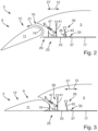
- a schematic cross sectional view across the span direction of a wing according to an embodiment of the invention with a focus on the trailing edge high lift assembly including the flap in an extended position,
- Fig. 3
- the wing shown in
Fig. 2 with the flap in a first retracted position, - Fig. 4
- the wing shown in
Fig. 2 with the flap in a second retracted position, - Fig. 5
- a detailed view of the transition from the closing panel to the lower rear panel of the main wing, as shown in
Fig. 2 . -
Fig. 1 shows anexemplary aircraft 1 according to an embodiment of the present invention. Theaircraft 1 comprises awing 3 including amain wing 5 mounted to afuselage 7, and a trailing edgehigh lift assembly 9 including aflap 11 movably mounted to themain wing 5. -
Figs. 2 to 5 illustrate an embodiment of thewing 3 of theaircraft 1 shown inFig. 1 . Thewing 3 comprises amain wing 5 and a trailing edgehigh lift assembly 9. The trailing edgehigh lift assembly 9 is movably arranged at a trailing edge of themain wing 5 and comprises aflap 11 and a connection assembly (not shown). The connection assembly movably mounts theflap 11 to themain wing 5, such that theflap 11 is movable between first and second retractedpositions wing 3, and anextended position 15 with an extended chord length and curvature of thewing 3. - In the extended position 15 a
gap 16 is present between a lowerrear panel 17 of themain wing 5 and aleading edge section 19 of theflap 11 to allow anair flow 21 to pass between theflap 11 and themain wing 5, in order to energize the air flow along the top surface of theflap 11. In the retractedpositions gap 16 is closed or minimized, so that anair flow 21 between theflap 11 and themain wing 5 is inhibited or at least minimized, in order to reduce drag. - The
flap 11 is movable between anextended position 15, as shown inFig. 2 , a first retractedposition 12, as shown inFig. 3 , and a second retractedposition 14, as shown inFig. 4 . The first retractedposition 12 in the present embodiment is a neutral retracted position intended for cruise flight under normal conditions. In the second retractedposition 14, which in the present embodiment is a negative retracted position, theflap 11 is moved beyond the first retractedposition 12 in aforward direction 13 further towards a leading edge of themain wing 5, thereby further reducing the chord length of thewing 3 compared to the first retractedposition 12. - Further, the
wing 3 comprises agap closing device 23 configured to close or minimize thegap 16 in both the first retracted position 12 (seeFig. 3 ) and the second retracted position 14 (seeFig. 4 ) of theflap 11, and to open thegap 16 in the at least one extended position 15 (seeFig. 2 ) of theflap 11. Thegap closing device 23 is a passive device and does not include an actuator. - The
gap closing device 23 comprises aclosing panel 25 forming an extension of the lowerrear panel 17 of themain wing 5 in therearward direction 27. The closingpanel 25 is movable relative to the lowerrear panel 17 of themain wing 5 between an elongated position 29 (seeFig. 2 and 3 ), where theclosing panel 25 forms a maximum extension of the lowerrear panel 17 of themain wing 5, and a shortened position 31 (seeFig. 4 ), where theclosing panel 25 forms a minimum extension of the lowerrear panel 17 of themain wing 5. Thegap closing device 23 is configured such that when theflap 11 is in theextended position 15 and in the first retractedposition 12 theclosing panel 25 is in theelongated position 29, while when theflap 11 is in the second retractedposition 14 theclosing panel 25 is in the shortenedposition 31. - The
gap closing device 23 is configured such that when theclosing panel 25 is moved from theelongated position 29 to the shortenedposition 31 theclosing panel 25 is moved behind the lowerrear panel 17 of themain wing 5, such that a part of theclosing panel 25 overlaps with the lowerrear panel 17 of themain wing 5. The closingpanel 25 at its forward end has astep 33 with a chamferededge 35, as shown inFig. 5 , such that in theelongated position 29 thestep 33 may engage arear end 37 of the lowerrear panel 17 of themain wing 5 and there is a smooth transition from the outer surface of theclosing panel 25 to the outer surface of the lowerrear panel 17 of themain wing 5, while when moved to the shortenedposition 31 thestep 33 is moved beyond therear end 37 of the lowerrear panel 17 of themain wing 5 and behind the lowerrear panel 17 of themain wing 5. Therear end 37 of the lowerrear panel 17 of themain wing 5 is also chamfered to correspond to and slide along the chamferededge 35 of thestep 33, when theclosing panel 25 is moved from theelongated position 29 to the shortenedposition 31, seeFig. 5 . - The
gap closing device 23 comprises alinkage 39 movably mounting theclosing panel 25 to themain wing 5. Thelinkage 39 comprises afirst link 41 and asecond link 43. Thefirst link 41 is rotatably mounted to themain wing 5 and is rotatably mounted to theclosing panel 25. Thesecond link 43 is rotatably mounted to themain wing 5 and is rotatably mounted to theclosing panel 25 at a position spaced apart from thefirst link 41. Therotatable joints 45 between the first andsecond links closing panel 25 on the one hand, and between the first andsecond links main wing 5 on the other hand, preferably have parallel axes of rotation and might also be realized as fixed body joints. - The closing
panel 25 comprises acatch element 45 configured for being contacted by theflap 11 when theflap 11 is moved between the first retractedposition 12 and the second retractedposition 14, so that by contact with thecatch element 45 theflap 11 may push theclosing panel 25 from theelongated position 29 to the shortenedposition 31 when theflap 11 is moved from the first retractedposition 12 to the second retractedposition 14. Thecatch element 45 is formed as a rod, panel, or other projection extending away from the inner surface of theclosing panel 25. Thecatch element 45 might comprise a flap contact roller (not shown) mounted directly or indirectly to theclosing panel 25 and configured for rolling contact with the leading edge section of theflap 11. - The
gap closing device 23 comprises a biasingmember 47 configured to bias theclosing panel 25 towards theflap 11, and thecatch element 45 in contact with the leading edge section of theflap 11, i.e. towards theelongated position 29. The biasingmember 47 in the present embodiment is a linear spring coupled between themain wing 5 and thefirst link 41. - The
gap closing device 23 further comprises astop member 49 configured to limit movement of theclosing panel 25 beyond theelongated position 29. I.e., thestop member 49 is configured such that movement of theclosing panel 25 towards theflap 11 is stopped at theelongated position 29. Thestop member 49 in the present embodiment is configured to be contacted by thesecond link 43, and is attached to themain wing 5. - By such a
wing 3 according to the invention introducing a second retractedposition 14 with reduced chord length, drag and structural loading can be further reduced and flight parameters can be optimized, while at the same time thegap 16 between the lowerrear panel 17 of themain wing 5 and theleading edge section 19 of theflap 11 can be kept closed by thegap closing device 23 in both the first retractedposition 12 and the second retractedposition 14, and can be kept open for air to pass through in theextended position 15, in order to achieve optimized aerodynamic performance throughout all positions of theflap 11.
Claims (15)
- A wing (3) for an aircraft (1), comprisinga main wing (5) anda trailing edge high lift assembly (9) movably arranged at a trailing edge of the main wing (5), the trailing edge high lift assembly (9) comprisinga flap (11) anda connection assembly movably mounting the flap (11) to the main wing (5), such that the flap (11) is movable between at least one retracted position (12, 14) and at least one extended position (15),wherein in the at least one extended position (15) a gap (16) is present between a lower rear panel (17) of the main wing (5) and a leading edge section (19) of the flap (11), andwherein in the at least one retracted position (12, 14) the gap (16) is closed or minimized,characterized in thatthe flap (11) is movable between at least one extended position (15), a first retracted position (12), and a second retracted position (14) where the flap (11) is moved beyond the first retracted position (12) in a forward direction (13), andthe wing comprises a gap closing device (23) configured to close or minimize the gap (16) in both the first retracted position (12) and the second retracted position (14) of the flap (11), and to open the gap (16) in the at least one extended position (15) of the flap.
- The wing (3) according to claim 1, wherein the gap closing device (23) is a passive device.
- The wing (3) according to claim 1 or 2, wherein the gap closing device (23) is movably mounted to the main wing (5).
- The wing (3) according to any of claims 1 to 3, wherein the gap closing device (23) is movable in one direction by contact with the flap (11) when the flap (11) is moved relative to the main wing (5) and is movable in the opposite direction by a biasing member (47).
- The wing (3) according to any of claims 1 to 3, wherein the gap closing device (23) comprises a closing panel (25) forming an extension of the lower rear panel (17) of the main wing (5) in a rearward direction (27), and
wherein the closing panel (25) is movable relative to the lower rear panel (17) of the main wing (5) between an elongated position (29) and a shortened position (31). - The wing (3) according to claim 5, wherein the gap closing device (23) is configured such that when the flap (11) is in the at least one extended position (15) and in the first retracted position (12) the closing panel (25) is in the elongated position (29), while when the flap (11) is in the second retracted position (14) the closing panel (25) is in the shortened position (31).
- The wing (3) according to claim 5 or 6, wherein the gap closing device (23) is configured such that when the closing panel (25) is moved from the elongated position (29) to the shortened position (31) the closing panel (25) is moved behind the lower rear panel (17) of the main wing (5), such that a part of the closing panel (25) overlaps with the lower rear panel (17) of the main wing (3).
- The wing (3) according to claim 7, wherein the closing panel (25) at its forward end has a step (33), such that in the elongated position (29) the step (33) may engage a rear end (37) of the lower rear panel (17) of the main wing (3) and there is a smooth transition from the outer surface of the closing panel (25) to the outer surface of the lower rear panel (17) of the main wing (3), while when moved to the shortened position (31) the step (33) is moved beyond the rear end (37) of the lower rear panel (17) of the main wing (5) behind the lower rear panel (17) of the main wing (5).
- The wing (3) according to any of claims 5 to 8, wherein the gap closing device (23) comprises a linkage (39) movably mounting the closing panel (25) to the main wing (5).
- The wing (3) according to claim 9, wherein the linkage (39) comprises a first link (41) and a second link (43),wherein the first link (41) is rotatably mounted to the main wing (5) and is rotatably mounted to the closing panel (25), andwherein the second link (43) is rotatably mounted to the main wing (5) and is rotatably mounted to the closing panel (25), at a position spaced apart from the first link (41).
- The wing (3) according to any of claims 5 to 10, wherein the closing panel (25) comprises a catch element (45) configured for being contacted by the flap (11) when the flap (11) is moved between the first retracted position (12) and the second retracted position (14).
- The wing (3) according to any of claims 5 to 11, wherein the gap closing device (23) comprises at least one biasing member (47) configured to bias the closing panel (25) towards the flap (11).
- The wing (3) according to any of claims 5 to 12, wherein the gap closing device (23) comprises at least one stop member (49) configured to limit movement of the closing panel beyond the elongated position (29).
- A gap closing device (23) for the wing (3) according to any of claims 1 to 13, comprisinga closing panel (25) configured to form an extension of the lower rear panel (17) of the main wing (5) in a rearward direction (27), anda linkage (39) configured for movably mounting the closing panel (25) to the main wing (5).
- An aircraft (1) comprising the wing (3) according to any of claims 1 to 13, and/or comprising the gap closing device (23) according to claim 14.
Priority Applications (3)
| Application Number | Priority Date | Filing Date | Title |
|---|---|---|---|
| EP22210458.0A EP4378827A1 (en) | 2022-11-30 | 2022-11-30 | Wing for an aircraft |
| US18/520,107 US12286229B2 (en) | 2022-11-30 | 2023-11-27 | Wing for an aircraft |
| CN202311611783.2A CN118107773A (en) | 2022-11-30 | 2023-11-28 | Wing for aircraft, gap closing device and aircraft |
Applications Claiming Priority (1)
| Application Number | Priority Date | Filing Date | Title |
|---|---|---|---|
| EP22210458.0A EP4378827A1 (en) | 2022-11-30 | 2022-11-30 | Wing for an aircraft |
Publications (1)
| Publication Number | Publication Date |
|---|---|
| EP4378827A1 true EP4378827A1 (en) | 2024-06-05 |
Family
ID=84367423
Family Applications (1)
| Application Number | Title | Priority Date | Filing Date |
|---|---|---|---|
| EP22210458.0A Pending EP4378827A1 (en) | 2022-11-30 | 2022-11-30 | Wing for an aircraft |
Country Status (3)
| Country | Link |
|---|---|
| US (1) | US12286229B2 (en) |
| EP (1) | EP4378827A1 (en) |
| CN (1) | CN118107773A (en) |
Families Citing this family (2)
| Publication number | Priority date | Publication date | Assignee | Title |
|---|---|---|---|---|
| EP4292924A1 (en) * | 2022-06-15 | 2023-12-20 | Airbus Operations GmbH | Sealing device for covering an aperture in a wing part |
| US12358610B1 (en) * | 2024-06-04 | 2025-07-15 | The Boeing Company | Mechanism for moving and maintaining position of an aircraft wing slat |
Citations (4)
| Publication number | Priority date | Publication date | Assignee | Title |
|---|---|---|---|---|
| US2169416A (en) * | 1936-06-12 | 1939-08-15 | United Aircraft Corp | Slotted deflector flap |
| US3493196A (en) * | 1968-01-24 | 1970-02-03 | Mc Donnell Douglas Corp | Airplane flap assembly |
| US20050011994A1 (en) * | 2003-06-03 | 2005-01-20 | Seiya Sakurai | Multi-function trailing edge devices and associated methods |
| GB2588766A (en) * | 2019-11-01 | 2021-05-12 | Airbus Operations Ltd | An aircraft wing with trailing edge flight control surface |
Family Cites Families (3)
| Publication number | Priority date | Publication date | Assignee | Title |
|---|---|---|---|---|
| US3921942A (en) * | 1974-07-01 | 1975-11-25 | Gen Dynamics Corp | Rudder boundary layer control device |
| US7258308B2 (en) * | 2002-07-02 | 2007-08-21 | The Boeing Company | Method and apparatus for controlling airflow with a gapped trailing edge device having a flexible flow surface |
| US11970269B2 (en) * | 2022-05-13 | 2024-04-30 | The Boeing Company | Assemblies for air vehicle control surfaces including a bullnose |
-
2022
- 2022-11-30 EP EP22210458.0A patent/EP4378827A1/en active Pending
-
2023
- 2023-11-27 US US18/520,107 patent/US12286229B2/en active Active
- 2023-11-28 CN CN202311611783.2A patent/CN118107773A/en active Pending
Patent Citations (4)
| Publication number | Priority date | Publication date | Assignee | Title |
|---|---|---|---|---|
| US2169416A (en) * | 1936-06-12 | 1939-08-15 | United Aircraft Corp | Slotted deflector flap |
| US3493196A (en) * | 1968-01-24 | 1970-02-03 | Mc Donnell Douglas Corp | Airplane flap assembly |
| US20050011994A1 (en) * | 2003-06-03 | 2005-01-20 | Seiya Sakurai | Multi-function trailing edge devices and associated methods |
| GB2588766A (en) * | 2019-11-01 | 2021-05-12 | Airbus Operations Ltd | An aircraft wing with trailing edge flight control surface |
Also Published As
| Publication number | Publication date |
|---|---|
| US20240174346A1 (en) | 2024-05-30 |
| CN118107773A (en) | 2024-05-31 |
| US12286229B2 (en) | 2025-04-29 |
Similar Documents
| Publication | Publication Date | Title |
|---|---|---|
| US8245982B2 (en) | Wing | |
| US12286229B2 (en) | Wing for an aircraft | |
| RU2464202C2 (en) | Aerofil section leading edge | |
| US12428133B2 (en) | Wing for an aircraft | |
| US11274633B2 (en) | Turbofan comprising a set of rotatable blades for blocking off the bypass flow duct | |
| US8567727B2 (en) | Trailing edge flap | |
| US11433988B2 (en) | Aircraft wing comprising a mobile leading edge flap guided by a device located at the front of a wing box | |
| EP3310652B1 (en) | Aircraft wing system | |
| AU2016278098B2 (en) | Aircraft wing system | |
| US20210061443A1 (en) | Flap actuation systems for aircraft | |
| US20200307760A1 (en) | Shutter door mechanism for wing leading edge slat cut-outs | |
| US12377961B2 (en) | Wing for an aircraft with damper for damping uncontrolled movement between leading edge part and trailing edge part | |
| US20230312080A1 (en) | Wing for an aircraft | |
| EP4311766A1 (en) | Wing for an aircraft | |
| EP1972547A1 (en) | Wing leading edge device | |
| US12312084B2 (en) | Wing for an aircraft having a flap with a speed brake panel mounted in a rotatable manner | |
| EP4378826B1 (en) | Wing for an aircraft | |
| US20210300522A1 (en) | Wing for aircraft | |
| US12612152B2 (en) | Wing for an aircraft | |
| US20260109449A1 (en) | Support assembly for a high lift body, high lift body arrangement, as well as wing and aircraft comprising same | |
| EP4613637A1 (en) | Wing for an aircraft |
Legal Events
| Date | Code | Title | Description |
|---|---|---|---|
| PUAI | Public reference made under article 153(3) epc to a published international application that has entered the european phase |
Free format text: ORIGINAL CODE: 0009012 |
|
| STAA | Information on the status of an ep patent application or granted ep patent |
Free format text: STATUS: THE APPLICATION HAS BEEN PUBLISHED |
|
| AK | Designated contracting states |
Kind code of ref document: A1 Designated state(s): AL AT BE BG CH CY CZ DE DK EE ES FI FR GB GR HR HU IE IS IT LI LT LU LV MC ME MK MT NL NO PL PT RO RS SE SI SK SM TR |
|
| STAA | Information on the status of an ep patent application or granted ep patent |
Free format text: STATUS: REQUEST FOR EXAMINATION WAS MADE |
|
| 17P | Request for examination filed |
Effective date: 20241205 |
|
| STAA | Information on the status of an ep patent application or granted ep patent |
Free format text: STATUS: EXAMINATION IS IN PROGRESS |
|
| 17Q | First examination report despatched |
Effective date: 20251014 |