EP4378721A1 - Axle assembly for an electric vehicle, vehicle, and method for operating an axle assembly - Google Patents
Axle assembly for an electric vehicle, vehicle, and method for operating an axle assembly Download PDFInfo
- Publication number
- EP4378721A1 EP4378721A1 EP22210775.7A EP22210775A EP4378721A1 EP 4378721 A1 EP4378721 A1 EP 4378721A1 EP 22210775 A EP22210775 A EP 22210775A EP 4378721 A1 EP4378721 A1 EP 4378721A1
- Authority
- EP
- European Patent Office
- Prior art keywords
- electric machine
- axle assembly
- machine
- shaft
- axle
- Prior art date
- Legal status (The legal status is an assumption and is not a legal conclusion. Google has not performed a legal analysis and makes no representation as to the accuracy of the status listed.)
- Pending
Links
Images

Classifications
-
- B—PERFORMING OPERATIONS; TRANSPORTING
- B60—VEHICLES IN GENERAL
- B60K—ARRANGEMENT OR MOUNTING OF PROPULSION UNITS OR OF TRANSMISSIONS IN VEHICLES; ARRANGEMENT OR MOUNTING OF PLURAL DIVERSE PRIME-MOVERS IN VEHICLES; AUXILIARY DRIVES FOR VEHICLES; INSTRUMENTATION OR DASHBOARDS FOR VEHICLES; ARRANGEMENTS IN CONNECTION WITH COOLING, AIR INTAKE, GAS EXHAUST OR FUEL SUPPLY OF PROPULSION UNITS IN VEHICLES
- B60K1/00—Arrangement or mounting of electrical propulsion units
- B60K1/02—Arrangement or mounting of electrical propulsion units comprising more than one electric motor
-
- B—PERFORMING OPERATIONS; TRANSPORTING
- B60—VEHICLES IN GENERAL
- B60K—ARRANGEMENT OR MOUNTING OF PROPULSION UNITS OR OF TRANSMISSIONS IN VEHICLES; ARRANGEMENT OR MOUNTING OF PLURAL DIVERSE PRIME-MOVERS IN VEHICLES; AUXILIARY DRIVES FOR VEHICLES; INSTRUMENTATION OR DASHBOARDS FOR VEHICLES; ARRANGEMENTS IN CONNECTION WITH COOLING, AIR INTAKE, GAS EXHAUST OR FUEL SUPPLY OF PROPULSION UNITS IN VEHICLES
- B60K17/00—Arrangement or mounting of transmissions in vehicles
- B60K17/02—Arrangement or mounting of transmissions in vehicles characterised by arrangement, location, or kind of clutch
-
- B—PERFORMING OPERATIONS; TRANSPORTING
- B60—VEHICLES IN GENERAL
- B60K—ARRANGEMENT OR MOUNTING OF PROPULSION UNITS OR OF TRANSMISSIONS IN VEHICLES; ARRANGEMENT OR MOUNTING OF PLURAL DIVERSE PRIME-MOVERS IN VEHICLES; AUXILIARY DRIVES FOR VEHICLES; INSTRUMENTATION OR DASHBOARDS FOR VEHICLES; ARRANGEMENTS IN CONNECTION WITH COOLING, AIR INTAKE, GAS EXHAUST OR FUEL SUPPLY OF PROPULSION UNITS IN VEHICLES
- B60K17/00—Arrangement or mounting of transmissions in vehicles
- B60K17/04—Arrangement or mounting of transmissions in vehicles characterised by arrangement, location or kind of gearing
- B60K17/16—Arrangement or mounting of transmissions in vehicles characterised by arrangement, location or kind of gearing of differential gearing
-
- B—PERFORMING OPERATIONS; TRANSPORTING
- B60—VEHICLES IN GENERAL
- B60K—ARRANGEMENT OR MOUNTING OF PROPULSION UNITS OR OF TRANSMISSIONS IN VEHICLES; ARRANGEMENT OR MOUNTING OF PLURAL DIVERSE PRIME-MOVERS IN VEHICLES; AUXILIARY DRIVES FOR VEHICLES; INSTRUMENTATION OR DASHBOARDS FOR VEHICLES; ARRANGEMENTS IN CONNECTION WITH COOLING, AIR INTAKE, GAS EXHAUST OR FUEL SUPPLY OF PROPULSION UNITS IN VEHICLES
- B60K17/00—Arrangement or mounting of transmissions in vehicles
- B60K17/04—Arrangement or mounting of transmissions in vehicles characterised by arrangement, location or kind of gearing
- B60K17/16—Arrangement or mounting of transmissions in vehicles characterised by arrangement, location or kind of gearing of differential gearing
- B60K17/165—Arrangement or mounting of transmissions in vehicles characterised by arrangement, location or kind of gearing of differential gearing provided between independent half axles
Definitions
- the present disclosure relates to an axle assembly for an electric vehicle.
- the present disclosure is further directed to a vehicle comprising such an axle assembly.
- the present disclosure is directed to a method for operating such an axle assembly.
- Known axle assemblies for electric vehicles usually comprise at least one electric machine and at least one transmission unit such that a drive power being generated by the electric machine can be provided to the driven wheels of the vehicle.
- an axle assembly for an electric vehicle.
- the axle assembly comprises a first electric machine, a second electric machine, and a spur gear unit comprising at least one spur gear stage and a differential gear unit.
- the at least one spur gear stage is drivingly coupled to the differential gear unit.
- an output shaft of the first electric machine, an output shaft of the second electric machine, and an input shaft of the spur gear stage are formed by a common shaft.
- the differential gear unit comprises a first output flange for drivingly coupling a first wheel to the axle assembly and a second output flange for drivingly coupling a second wheel to the axle assembly.
- the spur gear stage is to be understood as a non-shiftable spur gear stage.
- the spur gear stage can provide a single gear only.
- the input shaft of the spur gear stage is formed as a common shaft, it may be designated as a common input shaft.
- the common shaft is connected to both the first electric machine and the second electric machine.
- the spur gear unit is drivingly coupled to both the first electric machine and the second electric machine, it may be designated as a common spur gear unit.
- both the rotor of the first electric machine and the rotor of the second electric machine may be arranged on the common shaft. Consequently, the common shaft may be realized as one unitary continuous part.
- the common shaft and the subassembly comprising the common shaft, the first electric machine and the second electric machine may be realized in a compact manner. This offers the possibility to support the common shaft with relatively few bearings. This has the effect that friction occurring in bearings is avoided. In other words, the efficiency of the axle assembly is increased.
- a further advantage lies in the fact that two electric machines, i.e. the first electric machine and the second electric machine are used. This improves the packaging of the axle assembly.
- the first electric machine and the second electric machine may be electromagnetically optimized on different operational points or operational ranges. This has the effect that the axle assembly can be operated with high electromagnetic efficiency over a broad range of driving conditions. Altogether, the axle assembly of the present disclosure is highly efficient in a mechanical sense and in and electromagnetic sense.
- the spur gear unit only comprises one or more spur gear stages and one differential gear unit.
- the spur gear unit may consist of one or more spur gear stages and one differential gear unit.
- the spur gear unit may not comprise gear stages of other types such as planetary gear stages.
- the differential gear unit comprises a ring gear and a bevel gear unit having four bevel years being rotatorily supported on a bevel gear cage.
- the bevel gear cage is connected to the ring gear.
- a singular pinion is arranged on the common shaft.
- this is structurally simple. Since the singular pinion is arranged on the common shaft which is realized as both the output shaft of the first electric machine and the output shaft of the second electric machine, the singular pinion may be rotated by each of the first electric machine and the second electric machine alone or by both the first electric machine and the second electric machine together. Consequently, a broad range of operational modes is possible for such an axle assembly.
- the common shaft is supported on exactly two bearing units. More precisely, the common shaft is supported by the exactly two bearing units in a housing of the axle assembly or on a frame of the axle assembly. Especially when considering known axle assemblies, exactly two bearing units are relatively few bearing units. Since every bearing unit produces mechanical losses due to internal friction in the bearing unit, using fewer bearing units leads to an enhanced mechanical efficiency.
- the differential gear unit is supported on exactly two bearing units. More precisely, the differential gear unit is supported by the exactly two bearing units in a housing of the axle assembly or on a frame of the axle assembly. Especially when considering known axle assemblies, exactly two bearing units are relatively few bearing units. Since every bearing unit produces mechanical losses due to internal friction in the bearing unit, using fewer bearing units leads to an enhanced mechanical efficiency.
- the at least one spur gear stage comprises an intermediate shaft being arranged parallel to the common shaft. It is understood that the intermediate shaft and the common shaft are offset with respect to one another. Using an intermediate shaft allows the spur gear stage to provide a gear ratio of relatively big magnitude.
- the intermediate shaft is supported on exactly two bearing units. More precisely, the intermediate shaft is supported by the exactly two bearing units in a housing of the axle assembly or on a frame of the axle assembly. Especially when considering known axle assemblies, exactly two bearing units are relatively few bearing units. Since every bearing unit produces mechanical losses due to internal friction in the bearing unit, using fewer bearing units leads to an enhanced mechanical efficiency.
- the differential gear unit is rotatable around an axis of rotation which is arranged parallel to the common shaft. Again, the axis of rotation and the common shaft are offset with respect to one another.
- Such a configuration is structurally simple and reliable in operation.
- the first electric machine and the second electric machine are of the same type and/or have the same performance.
- the type of the first electric machine and the second electric machine relates to the working principle of the first electric machine and the second electric machine.
- the performance of the first electric machine and the second electric machine describes the capability of the first electric machine and the second electric machine to provide driving power. If the first electric machine and the second electric machine are of the same type and/or have the same performance, the first electric machine and the second electric machine may be identical at least in one of these respects. This renders the structure of the axle assembly simple. At the same time, the first electric machine and the second electric machine may be sourced using a same part strategy. This may reduce the costs of the axle assembly.
- a further advantage of this configuration lies in the fact that the first electric machine and the second electric machine may use a common or shared inverter unit.
- the first electric machine and the second electric machine differ in the respective type and/or the respective performance. This means that the first electric machine and the second electric machine use a different operational principle. Additionally or alternatively, the capabilities of the first electric machine and the second electric machine to provide driving power are different. This offers the possibility to have the first electric machine and the second electric machine optimized to different operational points or operational ranges. It is understood that electromagnetic losses of the first electric machine and the second electric machine are minimal in the respective operational point or range to which the first electric machine or the second electric machine is optimized. In an example, one of the first electric machine and the second electric machine may be optimized to an operational point which corresponds to a very common driving situation. The other one of the first electric machine and the second electric machine may be optimized to driving situations requiring high driving power.
- one of the first electric machine and the second electric machine may be called a main electric machine and the other one may be called an auxiliary electric machine.
- At least one of the first electric machine and the second electric machine is of a type that does not cause electromagnetic losses while rotating passively. This further increases the electromagnetic efficiency of the axle assembly.
- one out of the first electric machine and the second electric machine is an induction machine, a synchronous reluctance machine, a permanent magnet-assisted synchronous reluctance machine, a switched reluctance machine or an electrically excited rotor synchronous machine.
- the respective other one of the first electric machine and the second electric machine is a permanent magnet synchronous machine, an induction machine, a synchronous reluctance machine, a permanent magnet-assisted synchronous reluctance machine, a switched reluctance machine, an electrically excited rotor synchronous machine, a transverse flux machine or a variable flux machine.
- An induction machine a synchronous reluctance machine, a permanent magnet-assisted synchronous reluctance machine, a switched reluctance machine and an electrically excited rotor synchronous machine all have the advantage that they do not produce electromagnetic losses when being turned passively.
- electric machines are particularly suitable for being used as an auxiliary electric machine as has been described above. Altogether, the axle assembly is very efficient from an electromagnetic perspective.
- At least one of the first electric machine and the second electric machine comprises an external rotor.
- both the first electric machine and the second electric machine comprise an external rotor.
- Electric machines having an external rotor are comparatively short in an axial direction of the output shaft. This means that a corresponding dimension of the axle assembly is comparatively small.
- the first electric machine and/or the second electric machine only creates a relatively small overhang on the common shaft. This leads to a situation in which only comparatively few bearings are necessary in order to support the common shaft.
- the common shaft may be supported in a mechanically efficient manner.
- the axle assembly further comprises an inverter unit, wherein the inverter unit is at least partially arranged between the first electric machine and the second electric machine. Consequently, the axle assembly is relatively compact. Furthermore, as has already been explained above, depending on the configuration of the first electric machine and the second electric machine, the inverter unit may be a common or shared in inverter unit of both the first electric machine and the second electric machine.
- the inverter unit may be arranged in a pocket between the first electric machine and the second electric machine.
- the inverter unit may be arranged adjacent to the spur gear unit.
- inverter unit is arranged both in a pocket between the first electric machine and the second electric machine and adjacent to the spur gear unit. This is a particularly compact configuration.
- the axle assembly further comprises a first axle shaft being drivingly connected to the first output flange and a second axle shaft being drivingly connected to the second output flange.
- the first axle shaft and the second axle shaft have the same length.
- An end of each of the axle shafts being arranged opposite to the end being connected to the respective first output flange or second output flange is configured to be coupled to a wheel.
- Having a first axle shaft and a second axle shaft of the same length renders the axle assembly structurally simple.
- torque steering effects are avoided.
- such an axle assembly is balanced along a direction which corresponds to a direction of extension of the axle shafts. This direction may correspond to a transverse direction of a vehicle which uses the axle assembly.
- a vehicle comprising an axle assembly of the present disclosure.
- the differential gear unit is arranged centrally with respect to a vehicle width direction.
- the width direction of the vehicle extends perpendicular to a standard forward traveling direction of the vehicle.
- Arranging the differential gear unit centrally with respect to the width direction has the effect that the vehicle is balanced with respect to its width direction.
- axle shafts of the same length may be used and, thus, the advantages which have already been described above may be achieved.
- such a configuration makes it possible not to use additional bearings for the axle shafts. This enhances the mechanical efficiency of the axle assembly and of the vehicle as a whole.
- a method for operating an axle assembly of the present disclosure comprises:
- FIG. 1 shows a vehicle 10 which is an electric vehicle in the present example.
- the vehicle 10 comprises a pair of front wheels 12 and a pair of rear wheels 14.
- the rear wheels 14 are driven wheels.
- the left rear wheel 14 may be called a first wheel and the right rear wheel may be called a second wheel 14.
- axle assembly 16 is provided.
- the axle assembly 16 comprises a first electric machine 18 and a second electric machine 20.
- the axle assembly 16 comprises a spur gear unit 22 having a spur gear stage 24 and a differential gear unit 26.
- the axle assembly 16 is shown in more detail in Figure 2 .
- the first electric machine 18 comprises an internal stator 28 and an external rotor 30.
- the second electric machine 20 comprises an internal stator 32 and an external rotor 34.
- the first electric machine 18 and the second electric machine are of the same type.
- An output shaft of the first electric machine 18 and an output shaft of the second electric machine 20 are formed by a common shaft 36.
- the common shaft 36 is an input shaft of the spur gear stage 24.
- the common shaft 36 is supported on a housing 38 of the axle assembly 16 via exactly two bearing units 40, 42.
- a singular pinion 44 is arranged on the common shaft 36.
- the singular pinion 44 is rotationally fixed on the common shaft 36.
- the spur gear stage 24 additionally comprises an intermediate shaft 46.
- the intermediate shaft 46 is arranged in parallel to the common shaft 36.
- the intermediate shaft 46 and the common shaft 36 are offset from one another.
- the intermediate shaft is rotatorily supported on the housing 38 via exactly two bearing units 48, 50.
- a first gear 52 and a second gear 54 are rotationally fixed on the intermediate shaft 46.
- the first gear 52 engages the singular pinion 44.
- the first gear 52 and the singular pinion 44 form the spur gear stage 24.
- the spur gear stage 24 is coupled to the differential gear unit 26 via the second gear 54. In other words, the spur gear stage 24 is drivingly connected to the differential unit 26.
- the second gear 54 engages a ring gear 56 of the differential gear unit 26.
- the second gear 54 engaging the ring gear 56 is seen as a connection between the spur gear stage 24 and the differential gear unit 26 rather than a second spur gear stage.
- the ring gear 56 is fixed on a cage 58 of the differential gear unit 26. Moreover, inside the cage 58, a total of four bevel gears 60 are provided.
- differential gear unit 26 structurally corresponds to a generally known differential gear units, a detailed description of the interaction of the cage 58, the four bevel gears 60 and the ring gear 56 is omitted here.
- the cage 58, or more generally speaking the differential gear unit 26 is rotatably supported on the housing 38 by exactly two bearing units 62, 64.
- an axis of rotation of the differential gear unit 26 is parallel to the common shaft 36.
- the differential gear unit 26 comprises a first output flange 66 being provided on the bevel gear 60 shown on the left side in Figure 2 , and a second output flange 68 being provided on the bevel gear 60 shown on the right side in Figure 2 .
- a first axle shaft 70 is drivingly connected to the first output flange 66 and a second axle shaft 72 is drivingly connected to the second output flange 68.
- Each of the rear wheels 14 may be coupled to an end of the corresponding first axle shaft 70 or second axle shaft 72 which is remote from the differential gear unit 26. More precisely the first or left rear wheel 14 is connected to the first axle shaft 70 and the second or right rear wheel 14 is connected to the second axle shaft 72. Since the rear wheels 14 do not form part of the axle assembly 16, they are represented in dotted lines in Figure 2 .
- Both the first axle shaft 70 and the second axle shaft 72 have the same length.
- the differential gear unit 26 is arranged centrally with respect to a vehicle width direction W.
- the axle assembly 16 also comprises an inverter unit 74.
- the inverter unit 74 is a common or shared inverter unit 74. This means that the inverter unit 74 is used for powering both the first electric machine 18 and the second electric machine 20.
- the inverter unit 74 is partially arranged between the first electric machine 18 and the second electric machine 20.
- the inverter unit is arranged on top of the spur gear unit 22 and the differential gear unit 26.
- the axle assembly 16 may be operated using a method for operating an axle assembly.
- the first driving mode may be a low load mode.
- the first driving mode may be configured to be used in a standard driving situation.
- only the first electric machine 18 may be used in such a situation, i.e. in the first driving mode.
- a second driving mode may be used.
- both the first electric machine 18 and the second electric machine 20 may be operated.
- the second drivingly mode may be configured to be used in situations where high driving power is needed, for example if a strong acceleration is requested or if the vehicle 10 is driving up a steep hill.
- the second driving mode may be a high load mode.
- first electric machine 18 and the second electric machine 20 may be of different types.
- first electric machine may be a permanent magnet synchronous machine.
- the second electric machine may be an induction machine or a synchronous reluctance machine.
- Induction machines and synchronous reluctance machines have the advantage that they can be rotated passively without generating electromagnetic losses.
- axle assembly 16 according to this example may be operated using the method for operating an axle assembly as has been described above.
Landscapes
- Engineering & Computer Science (AREA)
- Chemical & Material Sciences (AREA)
- Combustion & Propulsion (AREA)
- Transportation (AREA)
- Mechanical Engineering (AREA)
- Retarders (AREA)
Abstract
The disclosure relates to an axle assembly (16) for an electric vehicle. The axle assembly (16) comprises a first electric machine (18), a second electric machine (20), and a spur gear unit (22) comprising at least one spur gear stage (24) and a differential gear unit (26). The at least one spur gear stage (24) is drivingly coupled to the differential gear unit (26). Moreover, an output shaft of the first electric machine (18), an output shaft of the second electric machine (20), and an input shaft of the spur gear stage (24) are formed by a common shaft (36). Additionally, the differential gear unit (26) comprises a first output flange (66) for drivingly coupling a first wheel (14) to the axle assembly (16) and a second output flange (68) for drivingly coupling a second wheel (14) to the axle assembly (16). Furthermore, a vehicle comprising such an axle assembly (16) is presented. The differential gear unit (26) is arranged centrally with respect to a vehicle width direction (W). Also a method for operating such an axle assembly (16) is described.
Description
- The present disclosure relates to an axle assembly for an electric vehicle.
- The present disclosure is further directed to a vehicle comprising such an axle assembly.
- Moreover, the present disclosure is directed to a method for operating such an axle assembly.
- Known axle assemblies for electric vehicles usually comprise at least one electric machine and at least one transmission unit such that a drive power being generated by the electric machine can be provided to the driven wheels of the vehicle.
- It is an objective of the present disclosure to increase the efficiency of such axle assemblies.
- The problem is at least partially solved or alleviated by the subject matter of the independent claims of the present disclosure, wherein further examples are incorporated in the dependent claims.
- According to a first aspect, there is provided an axle assembly for an electric vehicle. The axle assembly comprises a first electric machine, a second electric machine, and a spur gear unit comprising at least one spur gear stage and a differential gear unit. The at least one spur gear stage is drivingly coupled to the differential gear unit. Moreover, an output shaft of the first electric machine, an output shaft of the second electric machine, and an input shaft of the spur gear stage are formed by a common shaft. The differential gear unit comprises a first output flange for drivingly coupling a first wheel to the axle assembly and a second output flange for drivingly coupling a second wheel to the axle assembly. Thus, a drive power being generated by the first electric machine and/or the second electric machine can be transferred to the first output flange and the second output flange via the spur gear stage and the differential gear unit. In this context, the spur gear stage is to be understood as a non-shiftable spur gear stage. This means that the spur gear stage can provide a single gear only. Since the input shaft of the spur gear stage is formed as a common shaft, it may be designated as a common input shaft. The common shaft is connected to both the first electric machine and the second electric machine. Moreover, since the spur gear unit is drivingly coupled to both the first electric machine and the second electric machine, it may be designated as a common spur gear unit. In an example, both the rotor of the first electric machine and the rotor of the second electric machine may be arranged on the common shaft. Consequently, the common shaft may be realized as one unitary continuous part. Thus, the common shaft and the subassembly comprising the common shaft, the first electric machine and the second electric machine may be realized in a compact manner. This offers the possibility to support the common shaft with relatively few bearings. This has the effect that friction occurring in bearings is avoided. In other words, the efficiency of the axle assembly is increased. A further advantage lies in the fact that two electric machines, i.e. the first electric machine and the second electric machine are used. This improves the packaging of the axle assembly. Additionally, the first electric machine and the second electric machine may be electromagnetically optimized on different operational points or operational ranges. This has the effect that the axle assembly can be operated with high electromagnetic efficiency over a broad range of driving conditions. Altogether, the axle assembly of the present disclosure is highly efficient in a mechanical sense and in and electromagnetic sense.
- In an example, the spur gear unit only comprises one or more spur gear stages and one differential gear unit. In other words, the spur gear unit may consist of one or more spur gear stages and one differential gear unit. Thus, the spur gear unit may not comprise gear stages of other types such as planetary gear stages.
- In another example, the differential gear unit comprises a ring gear and a bevel gear unit having four bevel years being rotatorily supported on a bevel gear cage. The bevel gear cage is connected to the ring gear. This is a known configuration of a differential gear unit.
- In an example, a singular pinion is arranged on the common shaft. First of all, this is structurally simple. Since the singular pinion is arranged on the common shaft which is realized as both the output shaft of the first electric machine and the output shaft of the second electric machine, the singular pinion may be rotated by each of the first electric machine and the second electric machine alone or by both the first electric machine and the second electric machine together. Consequently, a broad range of operational modes is possible for such an axle assembly.
- In an example, the common shaft is supported on exactly two bearing units. More precisely, the common shaft is supported by the exactly two bearing units in a housing of the axle assembly or on a frame of the axle assembly. Especially when considering known axle assemblies, exactly two bearing units are relatively few bearing units. Since every bearing unit produces mechanical losses due to internal friction in the bearing unit, using fewer bearing units leads to an enhanced mechanical efficiency.
- In an example, the differential gear unit is supported on exactly two bearing units. More precisely, the differential gear unit is supported by the exactly two bearing units in a housing of the axle assembly or on a frame of the axle assembly. Especially when considering known axle assemblies, exactly two bearing units are relatively few bearing units. Since every bearing unit produces mechanical losses due to internal friction in the bearing unit, using fewer bearing units leads to an enhanced mechanical efficiency.
- In an example, the at least one spur gear stage comprises an intermediate shaft being arranged parallel to the common shaft. It is understood that the intermediate shaft and the common shaft are offset with respect to one another. Using an intermediate shaft allows the spur gear stage to provide a gear ratio of relatively big magnitude.
- In an example, the intermediate shaft is supported on exactly two bearing units. More precisely, the intermediate shaft is supported by the exactly two bearing units in a housing of the axle assembly or on a frame of the axle assembly. Especially when considering known axle assemblies, exactly two bearing units are relatively few bearing units. Since every bearing unit produces mechanical losses due to internal friction in the bearing unit, using fewer bearing units leads to an enhanced mechanical efficiency.
- In an example, the differential gear unit is rotatable around an axis of rotation which is arranged parallel to the common shaft. Again, the axis of rotation and the common shaft are offset with respect to one another. Such a configuration is structurally simple and reliable in operation.
- In an example, the first electric machine and the second electric machine are of the same type and/or have the same performance. In this context, the type of the first electric machine and the second electric machine relates to the working principle of the first electric machine and the second electric machine. The performance of the first electric machine and the second electric machine describes the capability of the first electric machine and the second electric machine to provide driving power. If the first electric machine and the second electric machine are of the same type and/or have the same performance, the first electric machine and the second electric machine may be identical at least in one of these respects. This renders the structure of the axle assembly simple. At the same time, the first electric machine and the second electric machine may be sourced using a same part strategy. This may reduce the costs of the axle assembly. A further advantage of this configuration lies in the fact that the first electric machine and the second electric machine may use a common or shared inverter unit.
- In an example, the first electric machine and the second electric machine differ in the respective type and/or the respective performance. This means that the first electric machine and the second electric machine use a different operational principle. Additionally or alternatively, the capabilities of the first electric machine and the second electric machine to provide driving power are different. This offers the possibility to have the first electric machine and the second electric machine optimized to different operational points or operational ranges. It is understood that electromagnetic losses of the first electric machine and the second electric machine are minimal in the respective operational point or range to which the first electric machine or the second electric machine is optimized. In an example, one of the first electric machine and the second electric machine may be optimized to an operational point which corresponds to a very common driving situation. The other one of the first electric machine and the second electric machine may be optimized to driving situations requiring high driving power. Consequently, in both of these driving situations, only a reduced amount of electromagnetic losses is produced. In other words, the axle assembly is highly efficient from the electromagnetic perspective. In such a configuration, one of the first electric machine and the second electric machine may be called a main electric machine and the other one may be called an auxiliary electric machine.
- In an example, at least one of the first electric machine and the second electric machine is of a type that does not cause electromagnetic losses while rotating passively. This further increases the electromagnetic efficiency of the axle assembly.
- In an example, one out of the first electric machine and the second electric machine is an induction machine, a synchronous reluctance machine, a permanent magnet-assisted synchronous reluctance machine, a switched reluctance machine or an electrically excited rotor synchronous machine. Alternatively or additionally, the respective other one of the first electric machine and the second electric machine is a permanent magnet synchronous machine, an induction machine, a synchronous reluctance machine, a permanent magnet-assisted synchronous reluctance machine, a switched reluctance machine, an electrically excited rotor synchronous machine, a transverse flux machine or a variable flux machine. An induction machine, a synchronous reluctance machine, a permanent magnet-assisted synchronous reluctance machine, a switched reluctance machine and an electrically excited rotor synchronous machine all have the advantage that they do not produce electromagnetic losses when being turned passively. Thus, such electric machines are particularly suitable for being used as an auxiliary electric machine as has been described above. Altogether, the axle assembly is very efficient from an electromagnetic perspective.
- In an example, at least one of the first electric machine and the second electric machine comprises an external rotor. In an example, both the first electric machine and the second electric machine comprise an external rotor. Electric machines having an external rotor are comparatively short in an axial direction of the output shaft. This means that a corresponding dimension of the axle assembly is comparatively small. Moreover, in such a configuration the first electric machine and/or the second electric machine only creates a relatively small overhang on the common shaft. This leads to a situation in which only comparatively few bearings are necessary in order to support the common shaft. Thus, the common shaft may be supported in a mechanically efficient manner.
- In an example, the axle assembly further comprises an inverter unit, wherein the inverter unit is at least partially arranged between the first electric machine and the second electric machine. Consequently, the axle assembly is relatively compact. Furthermore, as has already been explained above, depending on the configuration of the first electric machine and the second electric machine, the inverter unit may be a common or shared in inverter unit of both the first electric machine and the second electric machine.
- In an example, the inverter unit may be arranged in a pocket between the first electric machine and the second electric machine.
- In a further example, the inverter unit may be arranged adjacent to the spur gear unit.
- It is noted that the above-mentioned examples may also be combined such that the inverter unit is arranged both in a pocket between the first electric machine and the second electric machine and adjacent to the spur gear unit. This is a particularly compact configuration.
- In an example, the axle assembly further comprises a first axle shaft being drivingly connected to the first output flange and a second axle shaft being drivingly connected to the second output flange. The first axle shaft and the second axle shaft have the same length. An end of each of the axle shafts being arranged opposite to the end being connected to the respective first output flange or second output flange is configured to be coupled to a wheel. Having a first axle shaft and a second axle shaft of the same length renders the axle assembly structurally simple. Furthermore, torque steering effects are avoided. Moreover, such an axle assembly is balanced along a direction which corresponds to a direction of extension of the axle shafts. This direction may correspond to a transverse direction of a vehicle which uses the axle assembly.
- According to a second aspect, there is provided a vehicle comprising an axle assembly of the present disclosure. The differential gear unit is arranged centrally with respect to a vehicle width direction. In this context, the width direction of the vehicle extends perpendicular to a standard forward traveling direction of the vehicle. Arranging the differential gear unit centrally with respect to the width direction has the effect that the vehicle is balanced with respect to its width direction. At the same time, axle shafts of the same length may be used and, thus, the advantages which have already been described above may be achieved. Moreover, such a configuration makes it possible not to use additional bearings for the axle shafts. This enhances the mechanical efficiency of the axle assembly and of the vehicle as a whole.
- According to a third aspect, there is provided a method for operating an axle assembly of the present disclosure. The method comprises:
- operating only one out of the first electric machine and the second electric machine in a first driving mode, and
- operating both the first electric machine and the second electric machine in a second driving mode.
- It should be noted that the above examples may be combined with each other irrespective of the aspect involved.
- These and other aspects of the present disclosure will become apparent from and elucidated with reference to the examples described hereinafter.
- Examples of the disclosure will be described in the following with reference to the following drawings.
- Figure 1
- shows a vehicle according to the present disclosure having an axle assembly according to the present disclosure which may be operated using a method for operating an axle assembly according to the present disclosure,
- Figure 2
- shows the axle assembly of
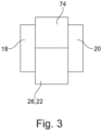
Figure 1 in a more detailed view, - Figure 3
- shows a further detailed view of the axle assembly of
Figure 1 along direction III inFigure 1 . - The Figures are merely schematic representations and serve only to illustrate examples of the disclosure. Identical or equivalent elements are in principle provided with the same reference signs.
-
Figure 1 shows avehicle 10 which is an electric vehicle in the present example. - The
vehicle 10 comprises a pair offront wheels 12 and a pair ofrear wheels 14. - The
rear wheels 14 are driven wheels. The leftrear wheel 14 may be called a first wheel and the right rear wheel may be called asecond wheel 14. - To this end, an
axle assembly 16 is provided. - The
axle assembly 16 comprises a firstelectric machine 18 and a secondelectric machine 20. - Moreover, the
axle assembly 16 comprises aspur gear unit 22 having aspur gear stage 24 and adifferential gear unit 26. - The
axle assembly 16 is shown in more detail inFigure 2 . - As can be seen therefrom, the first
electric machine 18 comprises aninternal stator 28 and anexternal rotor 30. - Also the second
electric machine 20 comprises aninternal stator 32 and anexternal rotor 34. - In the example shown in the Figures, the first
electric machine 18 and the second electric machine are of the same type. - An output shaft of the first
electric machine 18 and an output shaft of the secondelectric machine 20 are formed by acommon shaft 36. - At the same time, the
common shaft 36 is an input shaft of thespur gear stage 24. - The
common shaft 36 is supported on ahousing 38 of theaxle assembly 16 via exactly two bearingunits - Moreover, a
singular pinion 44 is arranged on thecommon shaft 36. Thesingular pinion 44 is rotationally fixed on thecommon shaft 36. - The
spur gear stage 24 additionally comprises anintermediate shaft 46. - The
intermediate shaft 46 is arranged in parallel to thecommon shaft 36. - The
intermediate shaft 46 and thecommon shaft 36 are offset from one another. - Also the intermediate shaft is rotatorily supported on the
housing 38 via exactly two bearingunits - A
first gear 52 and asecond gear 54 are rotationally fixed on theintermediate shaft 46. - The
first gear 52 engages thesingular pinion 44. - Thus, the
first gear 52 and thesingular pinion 44 form thespur gear stage 24. - The
spur gear stage 24 is coupled to thedifferential gear unit 26 via thesecond gear 54. In other words, thespur gear stage 24 is drivingly connected to thedifferential unit 26. - To this end, the
second gear 54 engages aring gear 56 of thedifferential gear unit 26. - It is noted that in the present example the
second gear 54 engaging thering gear 56 is seen as a connection between thespur gear stage 24 and thedifferential gear unit 26 rather than a second spur gear stage. - In the present example, the
ring gear 56 is fixed on acage 58 of thedifferential gear unit 26. Moreover, inside thecage 58, a total of fourbevel gears 60 are provided. - Since the
differential gear unit 26 structurally corresponds to a generally known differential gear units, a detailed description of the interaction of thecage 58, the fourbevel gears 60 and thering gear 56 is omitted here. - The
cage 58, or more generally speaking thedifferential gear unit 26 is rotatably supported on thehousing 38 by exactly two bearingunits - Thus, an axis of rotation of the
differential gear unit 26 is parallel to thecommon shaft 36. - Moreover, the
differential gear unit 26 comprises afirst output flange 66 being provided on thebevel gear 60 shown on the left side inFigure 2 , and asecond output flange 68 being provided on thebevel gear 60 shown on the right side inFigure 2 . - A
first axle shaft 70 is drivingly connected to thefirst output flange 66 and asecond axle shaft 72 is drivingly connected to thesecond output flange 68. - Each of the
rear wheels 14 may be coupled to an end of the correspondingfirst axle shaft 70 orsecond axle shaft 72 which is remote from thedifferential gear unit 26. More precisely the first or leftrear wheel 14 is connected to thefirst axle shaft 70 and the second or rightrear wheel 14 is connected to thesecond axle shaft 72. Since therear wheels 14 do not form part of theaxle assembly 16, they are represented in dotted lines inFigure 2 . - Both the
first axle shaft 70 and thesecond axle shaft 72 have the same length. - Moreover, the
differential gear unit 26 is arranged centrally with respect to a vehicle width direction W. - The
axle assembly 16 also comprises aninverter unit 74. - Since in the present example, the first
electric machine 18 and the secondelectric machine 20 are of the same type, theinverter unit 74 is a common or sharedinverter unit 74. This means that theinverter unit 74 is used for powering both the firstelectric machine 18 and the secondelectric machine 20. - As can best be seen in
Figure 3 , theinverter unit 74 is partially arranged between the firstelectric machine 18 and the secondelectric machine 20. - Moreover, the inverter unit is arranged on top of the
spur gear unit 22 and thedifferential gear unit 26. - The
axle assembly 16 may be operated using a method for operating an axle assembly. - According to this method, only one out of the first
electric machine 18 and the secondelectric machine 20 is operated in a first driving mode. The first driving mode may be a low load mode. - The first driving mode may be configured to be used in a standard driving situation. In the present example, only the first
electric machine 18 may be used in such a situation, i.e. in the first driving mode. - Alternatively, a second driving mode may be used. In this second driving mode, both the first
electric machine 18 and the secondelectric machine 20 may be operated. The second drivingly mode may be configured to be used in situations where high driving power is needed, for example if a strong acceleration is requested or if thevehicle 10 is driving up a steep hill. The second driving mode may be a high load mode. - In another example, the first
electric machine 18 and the secondelectric machine 20 may be of different types. In this context, the first electric machine may be a permanent magnet synchronous machine. The second electric machine may be an induction machine or a synchronous reluctance machine. - Induction machines and synchronous reluctance machines have the advantage that they can be rotated passively without generating electromagnetic losses.
- Also the
axle assembly 16 according to this example may be operated using the method for operating an axle assembly as has been described above. - Other variations to the disclosed examples can be understood and effected by those skilled in the art in practicing the claimed disclosure, from the study of the drawings, the disclosure, and the appended claims. In the claims the word "comprising" does not exclude other elements or steps and the indefinite article "a" or "an" does not exclude a plurality. The mere fact that certain measures are recited in mutually different dependent claims does not indicate that a combination of these measures cannot be used to advantage. Any reference signs in the claims should not be construed as limiting the scope of the claims.
-
- 10
- vehicle
- 12
- front wheel
- 14
- rear wheel
- 16
- axle assembly
- 18
- first electric machine
- 20
- second electric machine
- 22
- spur gear unit
- 24
- spur gear stage
- 26
- differential gear unit
- 28
- internal stator of the first electric machine
- 30
- external rotor of the first electric machine
- 32
- internal stator of the second electric machine
- 34
- external rotor of the second electric machine
- 36
- common shaft
- 38
- housing
- 40
- bearing unit
- 42
- bearing unit
- 44
- singular pinion
- 46
- intermediate shaft
- 48
- bearing unit
- 50
- bearing unit
- 52
- first gear
- 54
- second gear
- 56
- ring gear
- 58
- cage
- 60
- bevel gear
- 62
- bearing unit
- 64
- bearing unit
- 66
- first output flange
- 68
- second output flange
- 70
- first axle shaft
- 72
- second axle shaft
- 74
- inverter unit
- W
- vehicle width direction
Claims (15)
- An axle assembly (16) for an electric vehicle (10), comprisinga first electric machine (18),a second electric machine (20), anda spur gear unit (22) comprising at least one spur gear stage (24) and a differential gear unit (26), the at least one spur gear stage (24) being drivingly coupled to the differential gear unit (26),wherein an output shaft of the first electric machine (18), an output shaft of the second electric machine (20), and an input shaft of the spur gear stage (24) are formed by a common shaft (36), andwherein the differential gear unit (26) comprises a first output flange (66) for drivingly coupling a first wheel to the axle assembly (16) and a second output flange (68) for drivingly coupling a second wheel to the axle assembly (16).
- The axle assembly (16) of claim 1, wherein a singular pinion (44) is arranged on the common shaft (36).
- The axle assembly (16) of claim 1 or 2, wherein the common shaft (36) is supported on exactly two bearing units (40, 42).
- The axle assembly (16) of any one of the preceding claims, wherein the differential gear unit (26) is supported on exactly two bearing units (62, 64).
- The axle assembly (16) of any one of the preceding claims, wherein the at least one spur gear stage (24) comprises an intermediate shaft (46) being arranged parallel to the common shaft (36).
- The axle assembly (16) of claim 5, wherein the intermediate shaft (46) is supported on exactly two bearing units (48, 50).
- The axle assembly (16) of any one of the preceding claims, wherein the differential gear unit (26) is rotatable around an axis of rotation being arranged parallel to the common shaft (36).
- The axle assembly (16) of any one of the preceding claims, wherein the first electric machine (18) and the second electric machine (20) are of the same type and/or have the same performance.
- The axle assembly (16) of any one of claims 1 to 7, wherein the first electric machine (18) and the second electric machine (20) differ in the respective type and/or the respective performance.
- The axle assembly (16) of claim 9, wherein one out of the first electric machine (18) and the second electric machine (20) is an induction machine, a synchronous reluctance machine, a permanent magnet-assisted synchronous reluctance machine, a switched reluctance machine or an electrically excited rotor synchronous machine and/or wherein the respective other one of the first electric machine (18) and the second electric machine (20) is a permanent magnet synchronous machine, an induction machine, a synchronous reluctance machine, a permanent magnet-assisted synchronous reluctance machine, a switched reluctance machine, an electrically excited rotor synchronous machine, a transverse flux machine or a variable flux machine.
- The axle assembly (16) of any one of the preceding claims, wherein at least one of the first electric machine (18) and the second electric machine (20) comprises an external rotor (30, 34).
- The axle assembly (16) of any one of the preceding claims, further comprising an inverter unit (74), wherein the inverter unit (74) is at least partially arranged between the first electric machine (18) and the second electric machine (20).
- The axle assembly (16) of any one of the preceding claims, further comprising a first axle shaft (70) being drivingly connected to the first output flange (66) and a second axle shaft (72) being drivingly connected to the second output flange (68), wherein the first axle shaft (70) and the second axle shaft (72) have the same length.
- A vehicle (10) comprising an axle assembly (16) of any one of the preceding claims, wherein the differential gear unit (26) is arranged centrally with respect to a vehicle width direction (W).
- A method for operating an axle assembly (16) of any one of claims 1 to 13, comprising:- operating only one out of the first electric machine (18) and the second electric machine (20) in a first driving mode, and- operating both the first electric machine (18) and the second electric machine (20) in a second driving mode.
Priority Applications (2)
| Application Number | Priority Date | Filing Date | Title |
|---|---|---|---|
| EP22210775.7A EP4378721A1 (en) | 2022-12-01 | 2022-12-01 | Axle assembly for an electric vehicle, vehicle, and method for operating an axle assembly |
| US18/526,185 US12240308B2 (en) | 2022-12-01 | 2023-12-01 | Axle assembly for an electric vehicle, vehicle, and method for operating an axle assembly |
Applications Claiming Priority (1)
| Application Number | Priority Date | Filing Date | Title |
|---|---|---|---|
| EP22210775.7A EP4378721A1 (en) | 2022-12-01 | 2022-12-01 | Axle assembly for an electric vehicle, vehicle, and method for operating an axle assembly |
Publications (1)
| Publication Number | Publication Date |
|---|---|
| EP4378721A1 true EP4378721A1 (en) | 2024-06-05 |
Family
ID=84370062
Family Applications (1)
| Application Number | Title | Priority Date | Filing Date |
|---|---|---|---|
| EP22210775.7A Pending EP4378721A1 (en) | 2022-12-01 | 2022-12-01 | Axle assembly for an electric vehicle, vehicle, and method for operating an axle assembly |
Country Status (2)
| Country | Link |
|---|---|
| US (1) | US12240308B2 (en) |
| EP (1) | EP4378721A1 (en) |
Families Citing this family (1)
| Publication number | Priority date | Publication date | Assignee | Title |
|---|---|---|---|---|
| US11628713B2 (en) * | 2020-06-04 | 2023-04-18 | Rivian Ip Holdings, Llc | Electric vehicle powertrain assembly having nested shafts |
Citations (5)
| Publication number | Priority date | Publication date | Assignee | Title |
|---|---|---|---|---|
| US5289890A (en) * | 1991-12-10 | 1994-03-01 | Aisin Aw Co., Ltd. | Drive unit for electric motor vehicle |
| DE102011056928A1 (en) * | 2011-12-05 | 2013-06-06 | Dr. Ing. H.C. F. Porsche Aktiengesellschaft | Drive train for purely electrical all-wheel-driven motor vehicle e.g. sports car, has ring gears that are coupled via shaft, and pinions arranged at respective ends of shaft and engaged with respective ring gears |
| DE102018210897A1 (en) * | 2018-07-03 | 2020-01-09 | Zf Friedrichshafen Ag | Arrangement for driving an electric vehicle and method for operating it |
| FR3089886A1 (en) * | 2018-12-17 | 2020-06-19 | Valeo Embrayages | Electric vehicle propulsion system |
| US20220290749A1 (en) * | 2019-08-29 | 2022-09-15 | Aisin Corporation | Vehicle drive device |
Family Cites Families (11)
| Publication number | Priority date | Publication date | Assignee | Title |
|---|---|---|---|---|
| DE102011056047B4 (en) * | 2011-12-05 | 2024-07-04 | Dr. Ing. H.C. F. Porsche Aktiengesellschaft | Drivetrain of a purely electric all-wheel drive vehicle |
| DE102011056046B4 (en) * | 2011-12-05 | 2022-05-25 | Dr.Ing.H.C.F.Porsche Aktiengesellschaft | Drive train of a purely electric all-wheel drive motor vehicle |
| DE102012101209A1 (en) * | 2012-02-15 | 2013-08-22 | Dr. Ing. H.C. F. Porsche Aktiengesellschaft | Drive train of a purely electrically driven motor vehicle |
| US9199526B2 (en) * | 2013-02-26 | 2015-12-01 | Jtekt Corporation | Vehicle and vehicle driving device |
| WO2017160702A1 (en) * | 2016-03-15 | 2017-09-21 | Borgwarner Inc. | Twin system electric all-wheel drive supplementary drive axle |
| EP3475110A4 (en) * | 2016-08-01 | 2019-12-18 | Cummins, Inc. | CONTROL OF AN ELECTRIC MACHINE WITH INTEGRATED MOTOR |
| EP3409523A1 (en) * | 2017-05-30 | 2018-12-05 | FLET GmbH | Electric vehicle |
| DE102017127695A1 (en) * | 2017-11-23 | 2019-05-23 | Schaeffler Technologies AG & Co. KG | Hybrid powertrain with two electric machines and one internal combustion engine |
| EP3540918A1 (en) * | 2018-03-13 | 2019-09-18 | FLET GmbH | Electric vehicle |
| DE102019103131A1 (en) * | 2019-02-08 | 2020-08-13 | Minebea Mitsumi Inc. | Electric motor |
| US12558949B2 (en) * | 2022-05-04 | 2026-02-24 | Dana Belgium | Methods and systems for transmission and motors |
-
2022
- 2022-12-01 EP EP22210775.7A patent/EP4378721A1/en active Pending
-
2023
- 2023-12-01 US US18/526,185 patent/US12240308B2/en active Active
Patent Citations (5)
| Publication number | Priority date | Publication date | Assignee | Title |
|---|---|---|---|---|
| US5289890A (en) * | 1991-12-10 | 1994-03-01 | Aisin Aw Co., Ltd. | Drive unit for electric motor vehicle |
| DE102011056928A1 (en) * | 2011-12-05 | 2013-06-06 | Dr. Ing. H.C. F. Porsche Aktiengesellschaft | Drive train for purely electrical all-wheel-driven motor vehicle e.g. sports car, has ring gears that are coupled via shaft, and pinions arranged at respective ends of shaft and engaged with respective ring gears |
| DE102018210897A1 (en) * | 2018-07-03 | 2020-01-09 | Zf Friedrichshafen Ag | Arrangement for driving an electric vehicle and method for operating it |
| FR3089886A1 (en) * | 2018-12-17 | 2020-06-19 | Valeo Embrayages | Electric vehicle propulsion system |
| US20220290749A1 (en) * | 2019-08-29 | 2022-09-15 | Aisin Corporation | Vehicle drive device |
Also Published As
| Publication number | Publication date |
|---|---|
| US12240308B2 (en) | 2025-03-04 |
| US20240181859A1 (en) | 2024-06-06 |
Similar Documents
| Publication | Publication Date | Title |
|---|---|---|
| CN111664230B (en) | Drive unit for an electric vehicle and drive axle having a drive unit | |
| US9255633B2 (en) | Drive arrangement | |
| US12385554B2 (en) | Dual-motor driving system assembly and vehicle | |
| CN101657954B (en) | Nested variable field dynamoelectric machine | |
| JP3536837B2 (en) | Drive unit for hybrid vehicle | |
| JP4513492B2 (en) | Differential device and vehicle driving force transmission unit using the same | |
| EP1717086B2 (en) | Driveline motor with planetary gear system | |
| US7699737B2 (en) | Electric axle drive unit | |
| EP3936358A1 (en) | Dual-electric-motor driving system | |
| US9242538B2 (en) | Electrically driven vehicle drive axle arrangement | |
| US12240308B2 (en) | Axle assembly for an electric vehicle, vehicle, and method for operating an axle assembly | |
| US20240198792A1 (en) | Powertrain and electric vehicle | |
| JP2007039000A (en) | Power transmission device for hybrid vehicle | |
| CN119585131A (en) | Compact electric axle assemblies | |
| KR101927493B1 (en) | Transmission integral type electrical motor having double rotors | |
| CN101208217A (en) | Power transmission device for hybrid vehicle | |
| US20240247703A1 (en) | Transmission for a Coaxial Two-Machine Electric Drive of a Motor Vehicle | |
| CN105774765A (en) | Efficient electric braking wheel | |
| US20140302958A1 (en) | Drive device having an electrical drive machine | |
| GB2449489A (en) | Vehicle in-wheel motor generators with interposed differential | |
| CN214057235U (en) | Differential mechanism and direct drive motor integrated rear axle assembly | |
| JP2019173772A (en) | Rotary electric machine device and vehicle with the same | |
| US12377719B2 (en) | Drive device for a drive shaft comprising two rotating machines | |
| CN223850412U (en) | coaxial electric drive system | |
| EP4592115A1 (en) | Drive module and axle assembly for an electric vehicle, and electric vehicle |
Legal Events
| Date | Code | Title | Description |
|---|---|---|---|
| PUAI | Public reference made under article 153(3) epc to a published international application that has entered the european phase |
Free format text: ORIGINAL CODE: 0009012 |
|
| STAA | Information on the status of an ep patent application or granted ep patent |
Free format text: STATUS: REQUEST FOR EXAMINATION WAS MADE |
|
| 17P | Request for examination filed |
Effective date: 20230926 |
|
| AK | Designated contracting states |
Kind code of ref document: A1 Designated state(s): AL AT BE BG CH CY CZ DE DK EE ES FI FR GB GR HR HU IE IS IT LI LT LU LV MC ME MK MT NL NO PL PT RO RS SE SI SK SM TR |
|
| STAA | Information on the status of an ep patent application or granted ep patent |
Free format text: STATUS: EXAMINATION IS IN PROGRESS |
|
| 17Q | First examination report despatched |
Effective date: 20260311 |