EP4378543A1 - An injection assembly for containers - Google Patents
An injection assembly for containers Download PDFInfo
- Publication number
- EP4378543A1 EP4378543A1 EP23212809.0A EP23212809A EP4378543A1 EP 4378543 A1 EP4378543 A1 EP 4378543A1 EP 23212809 A EP23212809 A EP 23212809A EP 4378543 A1 EP4378543 A1 EP 4378543A1
- Authority
- EP
- European Patent Office
- Prior art keywords
- injection
- container
- passage
- adapter
- engaging end
- Prior art date
- Legal status (The legal status is an assumption and is not a legal conclusion. Google has not performed a legal analysis and makes no representation as to the accuracy of the status listed.)
- Pending
Links
Images



Classifications
-
- A—HUMAN NECESSITIES
- A62—LIFE-SAVING; FIRE-FIGHTING
- A62C—FIRE-FIGHTING
- A62C35/00—Permanently-installed equipment
- A62C35/02—Permanently-installed equipment with containers for delivering the extinguishing substance
- A62C35/023—Permanently-installed equipment with containers for delivering the extinguishing substance the extinguishing material being expelled by compressed gas, taken from storage tanks, or by generating a pressure gas
-
- A—HUMAN NECESSITIES
- A62—LIFE-SAVING; FIRE-FIGHTING
- A62C—FIRE-FIGHTING
- A62C35/00—Permanently-installed equipment
- A62C35/58—Pipe-line systems
- A62C35/68—Details, e.g. of pipes or valve systems
-
- F—MECHANICAL ENGINEERING; LIGHTING; HEATING; WEAPONS; BLASTING
- F17—STORING OR DISTRIBUTING GASES OR LIQUIDS
- F17C—VESSELS FOR CONTAINING OR STORING COMPRESSED, LIQUEFIED OR SOLIDIFIED GASES; FIXED-CAPACITY GAS-HOLDERS; FILLING VESSELS WITH, OR DISCHARGING FROM VESSELS, COMPRESSED, LIQUEFIED, OR SOLIDIFIED GASES
- F17C13/00—Details of vessels or of the filling or discharging of vessels
- F17C13/04—Arrangement or mounting of valves
Definitions
- the present invention relates to fire suppression systems and more particularly, to an injection assembly having an injection adapter for delivering pressurized gas in containers of a fire suppression system.
- Fire suppression systems are usually employed for discharging fire suppressing agents towards a fire.
- the fire suppression systems are provided with a storage container containing a fire suppressing agent which is discharged out of discharge nozzles in an area to extinguish the fire.
- the fire suppression systems are now deployed with a separate storage container containing a pressurized gas which is to be used for propelling the fire suppressing agent from the storage container at a higher pressure towards the discharged nozzles.
- a propellant pressure from the separate storage container is introduced, at a controlled rate, into a vapor space of the storage container containing the fire suppressing agent. This propellant pressure acts to propel the fire suppressing agent through a pipe system at the higher pressure.
- welded cylinders are employed for storing the fire suppressing agents.
- welded bosses are provided to facilitate a connection between the welded cylinder and the separate storage container containing the pressurized gas to be used as a booster for propelling the fire suppressing agent.
- containers such as seamless cylinders are usually employed for storing the fire suppressing agents.
- Such containers lacks any additional provision to facilitate connection with the separate storage container for receiving the pressurized gas. Therefore, implementation of the separate storage container for propelling the fire suppressing agent, at the higher flow rate, contained in the containers is cumbersome and cost-intensive.
- an injection adapter for injecting pressurized gas in containers.
- the injection adapter comprises a body adapted to be coaxially coupled to an opening of a container.
- the body comprises a discharge passage adapted to allow a flow of fire suppression agent from the container.
- the body comprises at least one injecting passage adapted to be in fluid communication with an ullage space of the container.
- the at least one injecting passage is adapted to supply pressurized gas from a canister to an ullage space within the container.
- the body comprises an outer surface and an inner surface distal to the outer surface.
- the inner surface defines the discharge passage adapted to be in fluid communication with a discharge valve assembly and a siphon tube inserted within the container.
- the at least one injecting passage is defined between the outer surface and the inner surface of the body.
- the body comprises a first engaging end adapted to be coaxially coupled with the discharge valve assembly. Further, the body comprises a second engaging end coaxial with respect to the first engaging end and is adapted to be coaxially coupled with the siphon tube. The first engaging end and the second engaging end define an outlet and an inlet, respectively, of the discharge passage.
- the second engaging end is adapted to be externally fastened to a neck portion of the container.
- the neck portion defines the opening, of the container, extending along a length of the neck portion.
- the second engaging end is adapted to be coaxially positioned within the neck portion of the container.
- the second engaging end is adapted to be internally fastened to the siphon tube.
- an injection inlet is formed on the outer surface of the body of the injection adapter, and an injection outlet is formed on a circumferential wall, of the body, surrounding the outlet of the discharge passage.
- the at least one injecting passage extends between the injection inlet and the injection outlet.
- the body is adapted to be coupled to at least one check valve having at least one connecting passage adapted to be aligned with the at least one injecting passage of the body to facilitate a fluid communication between the injection adapter and the at least one check valve adapter.
- an injection assembly for containers of a fire suppression system comprises an injection adapter having a body adapted to be coaxially coupled to an opening of a container.
- the body comprises a discharge passage and at least one injecting passage adapted to be in fluid communication with an ullage space of the container.
- the discharge passage is adapted to receive a flow of fire suppression agent from the container.
- the injection assembly comprises at least one check valve adapter coupled to the body of the injection adapter.
- the at least one check valve adapter comprises at least one connecting passage adapted to be aligned with the at least one injecting passage of the body to facilitate a fluid communication between the injection adapter and the at least one check valve adapter.
- the at one connecting passage allows a flow of pressurized gas within the ullage space of the container through the at least one injecting passage of the injection adapter.
- the body comprises an outer surface and an inner surface distal to the outer surface, the inner surface defines the discharge passage adapted to be in fluid communication with a discharge valve assembly and a siphon tube inserted within the container.
- the at least one injecting passage is defined between the outer surface and the inner surface of the body.
- the body comprises a first engaging end adapted to be coaxially coupled with the discharge valve assembly. Further, the body comprises a second engaging end coaxial with respect to the first engaging end and is adapted to be coaxially coupled with the siphon tube. The first engaging end and the second engaging end define an outlet and an inlet, respectively, of the discharge passage.
- the second engaging end is adapted to be externally fastened to a neck portion of the container.
- the neck portion defines the opening, of the container, extending along a length of the neck portion.
- the second engaging end is adapted to be coaxially positioned within the neck portion of the container.
- the second engaging end is adapted to be internally fastened to the siphon tube.
- an injection inlet is formed on the outer surface of the body of the injection adapter, and an injection outlet is formed on a circumferential wall, of the body, surrounding the outlet of the discharge passage.
- the at least one injecting passage extends between the injection inlet and the injection outlet.
- the at least one connecting passage comprises an inlet and an outlet adapted to be aligned with an injection inlet of the at least one injecting passage.
- At least one orifice plate is disposed between the injection inlet and the outlet of the at least one connecting passage. Further, at least one check valve is coupled to the inlet of the at least one connecting passage.
- a fire suppression system comprises at least one canister containing a pressurized gas. Further, the fire suppression system comprises at least one storage container in fluid communication with the at least one canister and contains a fire suppression agent.
- the fire suppression system comprises an injection assembly coupled to an opening of the at least one storage container.
- the injection assembly comprises an injection adapter having a discharge passage in fluid communication with the at least one storage container and at least one injecting passage in fluid communication with at least one canister and the at least one storage container.
- the fire suppression system comprises a discharge valve assembly coaxially coupled to an outlet of the discharge passage and adapted to discharge the fire suppression agent from the at least one storage container.
- the first suppression system comprises a siphon tube having a first end coaxially coupled to an inlet of the discharge passage and a second end positioned within the at least one storage container.
- the discharge passage allows a flow of the fire suppression agent from the siphon tube to the discharge valve assembly, and the at least one injecting passage supplies the pressurized gas from the at least one canister to an ullage space within the at least one storage container.
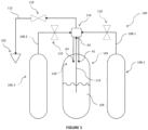
- Figure 1 illustrates an exemplary schematic view of a fire suppression system 100.
- the fire suppression system 100 may be employed to detect parameters, such as smoke, temperature, or other warning signs, associated with flammable elements, such as gases or any other flammable object present in a space and subsequently, extinguish flames arising from the flammable elements or prevent such flammable element from burning in a space based on the detection.
- the fire suppression system 100 may be automatically operated to extinguish the flames or prevent the flammable elements from burning based on the detection of parameters associated with the flammable element.
- the fire suppression system 100 may be manually operated from a remote location, such as a remote manual pull station.
- the fire suppression system 100 may include, but is not limited to, at least one nozzle 102, at least one storage container 104 in fluid communication with the at least one nozzle 102, and at least one canister 106 in fluid communication with the at least one storage container 104.
- the at least one canister 106 may be adapted to store a pressurized gas which is to be supplied to the at least one storage container 104.
- the pressurized gas may be embodied as one of nitrogen, argon, carbon dioxide, or a mixture thereof.
- the pressurized gas may be embodied as any inert gas known in the art.
- the fire suppression system 100 may include a first canister 106-1 and a second canister 106-2 to store the pressurized gas which is to be supplied to the at least one storage container 104.
- the fire suppression system 100 may include multiple canisters containing the pressurized gas.
- the fire suppression system 100 may include a piping system to fluidly connect the at least one storage container 104 with each of the first canister 106-1 and the second canister 106-2.
- the piping system may include, but is not limited to, a first injection conduit 108-1 to fluidly connect the first canister 106-1 with the at least one storage container 104 and a second injection conduit 108-2 to fluidly connect the second canister 106-2 with the at least one storage container 104.
- At least one control valve 110 may be positioned in each of the first injection conduit 108-1 and the second injection conduit 108-2 to control a flow of pressurized gas from each of the first canister 106-1 and the second canister 106-2 to the at least one storage container 104.
- the at least one storage container 104 may be adapted to store a fire suppression agent 105.
- the fire suppression system 100 may include a single storage container, i.e., the storage container 104, to store the fire suppression agent 105 which is to be supplied to the at least one nozzle 102.
- the fire suppression system 100 may include multiple storage containers containing the fire suppression agent 105.
- the at least one storage container 104 may be embodied as a seamless cylinder, a hot-forged cylinder, a cold-forged cylinder, and a tube-forged cylinder.
- the at least one storage container 104 may interchangeably be referred to as the container 104.
- the container 104 may be in fluid communication with the at least one nozzle 102 to supply the fire suppression agent 105.
- a discharge conduit 112 of the piping system may be configured to supply the fire suppression agent 105 to the at least one nozzle 102.
- the fire suppression system 100 may include, but is not limited to, a siphon tube 114, an injection assembly 116, and a discharge valve assembly 118.
- the siphon tube 114 may include a first end coupled to the injection assembly 116 and a second end positioned within the container 104. In one or more embodiments, the second end may be dipped in the fire suppression agent 105 stored within the container 104.
- the siphon tube 114 may facilitate the flow of the fire suppression agent 105 from the container 104, when the pressurized gas is supplied to an ullage space 120 and the discharge valve assembly 118 is operated to allow the flow of the fire suppression agent 105 to the at least one nozzle 102.
- the injection assembly 116 may be in fluid communication with the container 104, the first canister 106-1 via the first injection conduit 108-1, and the second canister 106-2 via the second injection conduit 108-2.
- the injection assembly 116 may be adapted to facilitate injection of the pressurized gas from canisters 106-1, 106-2 to the ullage space 120 of the container 104.
- arrows A1 and A2 indicate the injection of the pressurized gas in the ullage space 120 through the injection assembly 116.
- the injection assembly 116 may be in fluid communication with the discharge valve assembly 118 to facilitate supply of the fire suppression agent 105 through the siphon tube 114 from the container 104 to the discharge valve assembly 118.
- arrow A3 indicates the flow of the fire suppression agent 105 to the injection assembly 116 through the siphon tube 114.
- the fire suppression system 100 as depicted in Figure 1 is exemplary.
- the functionality of the fire suppression system 100 described herein is also exemplary.
- a person of ordinary skill in the art will appreciate that the fire suppression system 100 may additionally include other components and capabilities not described herein.
- Figure 2 illustrates an isometric view of the injection assembly 116 mounted on the container 104 of the fire suppression system 100.
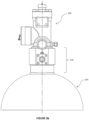
- Figures 3a and 3b illustrate planar views depicting the container 104 with the injection assembly 116.
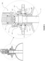
- Figure 4 illustrates an enlarged sectional view of the injection assembly 116 and the discharge valve assembly 118 mounted on the container 104.
- the injection assembly 116 may be coupled to the discharge valve assembly 118 and the siphon tube 114 which is inserted within the container 104.
- the injection assembly 116 may facilitate the flow of pressurized gas to the ullage space 120 of the container 104 and the flow of fire suppression agent 105 to the discharge valve assembly 118 from the container 104.
- the injection assembly 116 may include, but is not limited to, an injection adapter 402 and at least one check valve adapter 404.
- the injection adapter 402 may include a body 406 adapted to be coaxially coupled to the container 104.
- the body 406 may be coaxially coupled to an opening of the container 104.
- a neck portion 104-1 of the container 104 defines the opening extending along a length of the neck portion 104-1.
- the injection adapter 402 may facilitate a flow of the fire supressing agent 105 from the container 104 and injection of the pressurized gas in the ullage space 120 of the container 104 from a single opening, i.e., the opening defined by the neck portion 104-1.
- Figure 5 illustrates a sectional view of the injection assembly 116.
- the body 406 may include a first engaging end 502, an intermediate portion 506, and a second engaging end 504 coaxial with respect to the first engaging end 502 and the intermediate portion 506.
- the first engaging end 502 may be adapted to be coaxially coupled with the discharge valve assembly 118.
- the first engaging end 502 may include internal threads adapted to be engaged with external threads of the discharge valve assembly 118.
- the second engaging end 504 is adapted to be externally fastened to the neck portion 104-1 of the container 104.
- the second engaging end 504 may be adapted to be coaxially positioned within the neck portion 104-1 of the container 104.
- the second engaging end 504 may include external threads adapted to be engaged with internal threads of the neck portion 104-1.
- the second engaging end 504 may be adapted to be coaxially coupled with the siphon tube 114.
- the second engaging end 504 may be adapted to be internally fastened to the siphon tube 114.
- the second engaging end 504 may include internal threads adapted to be engaged with external threads of the siphon tube 114.
- a sealing ring 405, such as O-ring, may be disposed between the first engaging end 502 and the discharge valve assembly 118 to prevent leakage of the fire suppression agent 105.
- a sealing ring 407 may be disposed between the second engaging end 504 and the siphon tube 114 to prevent leakage of the fire suppression agent 105.
- the intermediate portion 506 of the body 406 may be disposed between the first engaging end 502 and the second engaging end 504 of the body 406.
- the intermediate portion 506 may be adapted to be coupled to the at least one check valve adapter 404. Constructional and operational details of the at least one check valve adapter 404 are explained in detail in the subsequent sections.
- the body 402 may include, but is not limited to, a discharge passage 408 and at least one injecting passage 410 adapted to be in fluid communication with the ullage space 120 of the container 104.
- the body 406 may include an outer surface 508-1 and an inner surface 508-2 distal to the outer surface 508-1.
- the inner surface 508-2 may define the discharge passage 408 adapted to be in fluid communication with the discharge valve assembly 118 and the siphon tube 114 inserted within the container 104.
- the discharge passage 408 may be adapted to receive a flow of fire suppression agent 105 from the container 104.
- the first engaging end 502 and the second engaging end 504 may define an outlet 509-1 and an inlet 509-2, respectively, of the discharge passage 408.
- the discharge passage 408 may receive the flow of fire suppression agent 105 from the siphon tube 114 through the inlet 509-2, and subsequently, the outlet 508-1 of the discharge passage 408 allows the flow of fire suppression agent 105 towards the discharge valve assembly 118.
- the discharge passage 408 may be coaxial with respect to the siphon tube 114 coupled to the second engaging end 504 and the discharge valve assembly 118 coupled to the first engaging end 502.
- the discharge valve assembly 118 may include, but is not limited to, an outlet (not shown), a resilient member 412 such as a spring, and a piston assembly 414.
- the piston assembly 414 may be adapted to be actuated by the flow of the fire suppression agent 105 received from the discharge passage 408 of the injection adapter 402.
- the piston assembly 414 may be actuated to allow the flow of the fire suppression agent 105 to be discharged through the outlet, of the discharge valve assembly 118, towards the at least one nozzle 102 of the fire suppression system 100.
- the discharge valve assembly 118 as depicted in the Figures 2 , 3a-3b , and 4 is exemplary.
- the functionality of the discharge valve assembly 118 described herein is also exemplary. A person of ordinary skill in the art will appreciate that the discharge valve assembly 118 may additionally include other components and capabilities not described herein.
- the injection adapter 402 may also include the at least one injecting passage 410 to allow the flow of pressurized gas from the at least one canister 106-1, 106-2 to the ullage space 120 of the container 104.
- the body 406 of the injection adapter 402 may include a pair of injecting passages 410-1, 410-2.
- the injection assembly 116 is explained with respect to the injection adapter 402 having two injecting passages 410-1, 410-2. It should not be construed as limiting, and the injection adapter 402 may include one or more injecting passages to be connected to one or more canisters 106 containing the pressurized gas.
- each of the pair of injecting passages 410-1, 410-2 may be defined between the outer surface 508-1 and the inner surface 508-2 of the body 406.
- Each of the pair of injecting passages 410-1, 410-2 may include a first portion 510-1 extending parallel to the discharge passage 408 of the body 406 and a second portion 510-2 extending laterally from the first portion 510-1 in a direction towards the outer surface 508-1 of the body 406.
- the first portion 510-1 and the second portion 510-2 may be in fluid communication with each other.
- the first portion 510-1 may be orthogonally formed with respect to the second portion 510-2.
- an injection inlet 512 may be formed on the outer surface 508-1 of the body 406. Further, an injection outlet 514 may be formed on a circumferential wall 516, of the body 406, surrounding the outlet 509-2 of the discharge passage 408. Each of the pair of injecting passages 410-1, 410-2 may extend between the injection inlet 512 and the injection outlet 514.
- the injection adapter 402 may be coupled to the neck portion 104-1 of the container 104 in a manner that the injection outlet 514 of each of the pair of injecting passages 410-1, 410-2 is in fluid communication with the ullage space 120 of the container 104.
- the injection assembly 116 may include the at least one check valve adapter 404 coupled to the body 406 of the injection adapter 402.
- the injection assembly 116 may include a first check valve adapter 404-1 and a second check valve adapter 404-2.
- the injection assembly 116 is explained with respect to the injection adapter 402 coupled to two check valve adapters 404-1, 404-2. It should not be construed as limiting, and the injection assembly 116 may include one or more check valve adapters.
- a number of the check valve adapters 404 to be deployed for the injection assembly 116 may vary based on a number of the injecting passages 410 provided within the injection adapter 402 of the injection assembly 116.
- the first check valve adapter 404-1 may be coupled to the outer surface 508-1 of the injection adapter 402 in a manner that an injecting passage, such as the injecting passage 410-1, may facilitate a fluid communication between the first check valve adapter 404-1 and the ullage space 120 of the container 104.
- the second check valve adapter 404-2 may be coupled to the outer surface 508-1 of the injection adapter 402 in a manner that an injecting passage, such as the injecting passage 410-2, may facilitate a fluid communication between the second check valve adapter 404-1 and the ullage space 120 of the container 104.
- the first check valve adapter 404-1 and the second check valve adapter 404-2 may be coupled to the outer surface 508-1 via fasteners, such as screws.
- each of the check valve adapters 404-1, 404-2 may include at least one connecting passage 518 adapted to be aligned with the at least one injecting passage, such as the injecting passages 410-1, 410-2, of the body 406 to define a fluid communication between the injection adapter 402 and each of the check valve adapters 404-1, 404-2.
- the first check valve adapter 404-1 and the second check valve adapter 404-2 may include a first connecting passage 518-1 and a second connecting passage 518-2, respectively.
- the first connecting passage 518-1 and the second connecting passage 518-2 may collectively be referred to as the connecting passages 518-1, 518-2.
- Each of the connecting passages 518-1, 518-2 may be adapted to allow the flow of pressurized gas within the ullage space 120 of the container 104 through one of the injecting passages 410-1, 410-2 of the injection adapter 402.
- Each of the connecting passages 518-1, 518-2 may include an inlet 520 and an outlet 522 adapted to be aligned with the injection inlet 512 of one of the injecting passages 410-1, 410-2.
- the outlet 522 of the first connecting passage 518-1 may be aligned with the injection inlet 512 of the injection passage 410-1.
- the outlet 522 of the second connecting passage 518-2 may be aligned with the injection inlet 512 of the injection passage 410-2.
- the first check valve adapter 404-1 may be coupled to the injection adapter in a manner that the first connecting passage 518-1 allows the flow of pressurized gas, from the first canister 106-1, within the ullage space 120 through the injecting passage 410-1 of the injection adapter 402.
- the second check valve adapter 404-2 may be coupled to the injection adapter in a manner that the second connecting passage 518-2 allows the flow of pressurized gas, from the second canister 106-2, within the ullage space 120 through the injecting passage 410-2 of the injection adapter 402.
- a sealing ring 524 such as an O-ring
- a sealing ring 526 such as an O-ring
- a sealing ring 526 may be disposed between the second check valve adapter 404-2 and the outer surface 508-1 of the injection adapter 402 to prevent leakage of the pressurized gas.
- the injection assembly 116 may include, but is not limited to, at least one orifice plate 528 disposed between the injection inlet 512 and the outlet 522 of the at least one connecting passage 518-1, 518-2.
- an orifice plate 528-1 may be disposed between the injection inlet 512 of the injecting passage 410-1 and the outlet 522 of the first connecting passage 518-1.
- an orifice plate 528-2 may be disposed between the injection inlet 512 of the injecting passage 410-2 and the outlet 522 of the second connecting passage 518-2.
- Each of the orifice plates 528-1, 528-2 may facilitate metering of the flow of pressurized gas from the at least one canister, such as 106-1, 106-2, to the container 104.
- canister such as 106-1, 106-2
- orifice plates with different operational and dimensional characteristics can be employed in the injection assembly 116.
- the injection assembly 116 may include, but is not limited to, at least one check valve 530 coupled to the inlet 520 of the at least one connecting passage 518-1, 518-2.
- a check valve 530-1 may be fastened to the inlet 520 of the first connecting passage 518-1.
- the check valve 530-1 may include external threads adapted to be engaged with internal threads of the first check valve adaptor 404-1. Referring to Figure 1 and Figure 5 , one end of the check valve 530-1 may be fluidly coupled to the first canister 106-1 via the first injection conduit 108-1.
- the check valve 530-1 may allow the pressurized gas to flow from the first canister 106-1 to the first check valve adapter 404-1 and subsequently, to the injecting passage 410-1.
- a check valve 530-2 may be fastened to the inlet 520 of the second connecting passage 518-2.
- the check valve 530-2 may include external threads adapted to be engaged with internal threads of the second check valve adaptor 404-2.
- one end of the check valve 530-2 may be fluidly coupled to the second canister 106-2 via the second injection conduit 108-2.
- the check valve 530-2 may allow the pressurized gas to flow from the second canister 106-2 to the second check valve adapter 404-2 and subsequently, to the injecting passage 410-2.
- a flare fitting 532 may be coupled to the check valve 530-1 and a plug 534 may be coupled be coupled to the check valve 530-2.
- the flare fitting 532 may be connected to an actuator disposed at a top of the discharge valve assembly 118.
- the pressurized gas may be supplied from the first canister 106-1 and the second canister 106-2 to the first connecting passage 518-1 of the first check valve adapter 404-1 and the second connecting passage 518-2 of the second check valve adapter 404-2. Subsequently, the injecting passage 410-1 may receive the pressurized gas through the first connecting passage 518-1 and, the injecting passage 410-2 may receive the pressurized gas through the second connecting passage 518-2. Thereafter, the pressurized gas may be injected in the ullage space 120 from the injection outlet 514 of each of the injection passages 410-1, 410-2.
- the fire suppression agent 105 may rise within the siphon tube 114 towards the inlet 509-2 of the discharge passage 408 of the injection adapter 402. Subsequently, the fire suppression agent 105 may enter within the discharge passage 408.
- a pressure may be delivered to the flare fitting 532. Subsequently, the pressure through the flare fitting 532 may be delivered to a pressure operated control head (not shown) which allows the piston assembly 414 to move upward and allowing the flow of the fire suppression agent 105 towards the at least one nozzle 102 of the fire suppression system 100.
- the disclosure offers the injection assembly 116 for injecting pressurized gas within the container 104 of the fire suppression system 100.
- the injection assembly 116 includes the injection adapter 402 which can be coupled to the opening of the container 104.
- the injection adapter 402 includes the discharge passage to allow the flow of the fire suppressing agent 105 from the container 104 and the injecting passages to allow injection of the pressurized gas in the ullage space of the container 104. Therefore, implementation of the injection adapter 402 enables the functionality of discharging the fire suppressing agent 105 and injecting the pressurized gas in the ullage space through a single opening, i.e., the opening defined by the neck portion, of the container 104. Therefore, the injection assembly 116 is compact, efficient, durable, flexible in implementation, cost-effective, light-weight, and convenient.
Landscapes
- Health & Medical Sciences (AREA)
- Public Health (AREA)
- Business, Economics & Management (AREA)
- Emergency Management (AREA)
- Engineering & Computer Science (AREA)
- Mechanical Engineering (AREA)
- General Engineering & Computer Science (AREA)
- Filling Or Discharging Of Gas Storage Vessels (AREA)
Abstract
Description
- The present invention relates to fire suppression systems and more particularly, to an injection assembly having an injection adapter for delivering pressurized gas in containers of a fire suppression system.
- Fire suppression systems are usually employed for discharging fire suppressing agents towards a fire. The fire suppression systems are provided with a storage container containing a fire suppressing agent which is discharged out of discharge nozzles in an area to extinguish the fire. With the advancement in technology, the fire suppression systems are now deployed with a separate storage container containing a pressurized gas which is to be used for propelling the fire suppressing agent from the storage container at a higher pressure towards the discharged nozzles. In such systems, a propellant pressure from the separate storage container is introduced, at a controlled rate, into a vapor space of the storage container containing the fire suppressing agent. This propellant pressure acts to propel the fire suppressing agent through a pipe system at the higher pressure.
- Currently, welded cylinders are employed for storing the fire suppressing agents. In such welded cylinders, welded bosses are provided to facilitate a connection between the welded cylinder and the separate storage container containing the pressurized gas to be used as a booster for propelling the fire suppressing agent. However, in some fire suppression systems, containers, such as seamless cylinders are usually employed for storing the fire suppressing agents. Such containers lacks any additional provision to facilitate connection with the separate storage container for receiving the pressurized gas. Therefore, implementation of the separate storage container for propelling the fire suppressing agent, at the higher flow rate, contained in the containers is cumbersome and cost-intensive.
- This summary is provided to introduce a selection of concepts, in a simplified format, that are further described in the detailed description. This summary is neither intended to identify key or essential inventive concepts of the invention, nor is it intended for determining the scope of the invention.
- In one or more embodiments of the invention, an injection adapter for injecting pressurized gas in containers is provided. The injection adapter comprises a body adapted to be coaxially coupled to an opening of a container. The body comprises a discharge passage adapted to allow a flow of fire suppression agent from the container. Further, the body comprises at least one injecting passage adapted to be in fluid communication with an ullage space of the container. The at least one injecting passage is adapted to supply pressurized gas from a canister to an ullage space within the container.
- In one or more embodiments of the invention, the body comprises an outer surface and an inner surface distal to the outer surface. The inner surface defines the discharge passage adapted to be in fluid communication with a discharge valve assembly and a siphon tube inserted within the container.
- In one or more embodiments of the invention, the at least one injecting passage is defined between the outer surface and the inner surface of the body.
- In one or more embodiments of the invention, the body comprises a first engaging end adapted to be coaxially coupled with the discharge valve assembly. Further, the body comprises a second engaging end coaxial with respect to the first engaging end and is adapted to be coaxially coupled with the siphon tube. The first engaging end and the second engaging end define an outlet and an inlet, respectively, of the discharge passage.
- In one or more embodiments of the invention, the second engaging end is adapted to be externally fastened to a neck portion of the container. The neck portion defines the opening, of the container, extending along a length of the neck portion.
- In one or more embodiments of the invention, the second engaging end is adapted to be coaxially positioned within the neck portion of the container.
- In one or more embodiments of the invention, the second engaging end is adapted to be internally fastened to the siphon tube.
- In one or more embodiments of the invention, an injection inlet is formed on the outer surface of the body of the injection adapter, and an injection outlet is formed on a circumferential wall, of the body, surrounding the outlet of the discharge passage. The at least one injecting passage extends between the injection inlet and the injection outlet.
- In one or more embodiments of the invention, the body is adapted to be coupled to at least one check valve having at least one connecting passage adapted to be aligned with the at least one injecting passage of the body to facilitate a fluid communication between the injection adapter and the at least one check valve adapter.
- In another embodiment of the invention, an injection assembly for containers of a fire suppression system is disclosed. The injection assembly comprises an injection adapter having a body adapted to be coaxially coupled to an opening of a container. The body comprises a discharge passage and at least one injecting passage adapted to be in fluid communication with an ullage space of the container. The discharge passage is adapted to receive a flow of fire suppression agent from the container. Further, the injection assembly comprises at least one check valve adapter coupled to the body of the injection adapter. The at least one check valve adapter comprises at least one connecting passage adapted to be aligned with the at least one injecting passage of the body to facilitate a fluid communication between the injection adapter and the at least one check valve adapter. The at one connecting passage allows a flow of pressurized gas within the ullage space of the container through the at least one injecting passage of the injection adapter.
- In one or more embodiments of the invention, the body comprises an outer surface and an inner surface distal to the outer surface, the inner surface defines the discharge passage adapted to be in fluid communication with a discharge valve assembly and a siphon tube inserted within the container.
- In one or more embodiments of the invention, the at least one injecting passage is defined between the outer surface and the inner surface of the body.
- In one or more embodiments of the invention, the body comprises a first engaging end adapted to be coaxially coupled with the discharge valve assembly. Further, the body comprises a second engaging end coaxial with respect to the first engaging end and is adapted to be coaxially coupled with the siphon tube. The first engaging end and the second engaging end define an outlet and an inlet, respectively, of the discharge passage.
- In one or more embodiments of the invention, the second engaging end is adapted to be externally fastened to a neck portion of the container. The neck portion defines the opening, of the container, extending along a length of the neck portion.
- In one or more embodiments of the invention, the second engaging end is adapted to be coaxially positioned within the neck portion of the container.
- In one or more embodiments of the invention, the second engaging end is adapted to be internally fastened to the siphon tube.
- In one or more embodiments of the invention, an injection inlet is formed on the outer surface of the body of the injection adapter, and an injection outlet is formed on a circumferential wall, of the body, surrounding the outlet of the discharge passage. The at least one injecting passage extends between the injection inlet and the injection outlet.
- In one or more embodiments of the invention, the at least one connecting passage comprises an inlet and an outlet adapted to be aligned with an injection inlet of the at least one injecting passage.
- In one or more embodiments of the invention, at least one orifice plate is disposed between the injection inlet and the outlet of the at least one connecting passage. Further, at least one check valve is coupled to the inlet of the at least one connecting passage.
- In yet another embodiment of the invention, a fire suppression system is provided. The fire suppression system comprises at least one canister containing a pressurized gas. Further, the fire suppression system comprises at least one storage container in fluid communication with the at least one canister and contains a fire suppression agent. The fire suppression system comprises an injection assembly coupled to an opening of the at least one storage container. The injection assembly comprises an injection adapter having a discharge passage in fluid communication with the at least one storage container and at least one injecting passage in fluid communication with at least one canister and the at least one storage container. The fire suppression system comprises a discharge valve assembly coaxially coupled to an outlet of the discharge passage and adapted to discharge the fire suppression agent from the at least one storage container. Further, the first suppression system comprises a siphon tube having a first end coaxially coupled to an inlet of the discharge passage and a second end positioned within the at least one storage container. The discharge passage allows a flow of the fire suppression agent from the siphon tube to the discharge valve assembly, and the at least one injecting passage supplies the pressurized gas from the at least one canister to an ullage space within the at least one storage container.
- To further clarify the advantages and features of the methods, systems, and apparatuses/devices, a more particular description of the methods, systems, and apparatuses/devices will be rendered by reference to specific embodiments thereof, which are illustrated in the appended drawings. It is appreciated that these drawings depict only exemplary embodiments of the invention and are therefore not to be considered limiting of its scope. Exemplary embodiments of the invention will be described and explained with additional specificity and detail with the accompanying drawings.
- These and other features, aspects, and advantages of the embodiments of the invention will become better understood when the following detailed description is read with reference to the accompanying drawings in which like characters represent like parts throughout the drawings, wherein:
-
Figure 1 illustrates an exemplary schematic view of a fire suppression system; -
Figure 2 illustrates an isometric view of an injection assembly mounted on a container of the fire suppression system; -
Figures 3a and3b illustrate planar views depicting the container with the injection assembly; -
Figure 4 illustrates an enlarged sectional view of the injection assembly and a valve assembly mounted on the container; and -
Figure 5 illustrates a sectional view of the injection assembly. - Further, skilled artisans will appreciate that elements in the drawings are illustrated for simplicity and may not have necessarily been drawn to scale. For example, the flow charts illustrate the method in terms of the most prominent steps involved to help to improve understanding. Furthermore, in terms of the construction of the device, one or more components of the device may have been represented in the drawings by conventional symbols, and the drawings may show only those specific details that are pertinent to understanding the embodiments so as not to obscure the drawings with details that will be readily apparent to those of ordinary skill in the art having the benefit of the description herein.
- For the purpose of promoting an understanding of the principles of the invention, reference will now be made to the various embodiments and specific language will be used to describe the same. It will nevertheless be understood that no limitation of the scope of the invention is thereby intended.
- It will be understood by those skilled in the art that the foregoing general description and the following detailed description are explanatory and are not intended to be restrictive of the scope of the invention, which is defined by the claims.
- Reference throughout this specification to "an aspect", "another aspect" or similar language means that a particular feature, structure, or characteristic described in connection with the embodiment is included in at least one embodiment of the disclosure. Thus, appearances of the phrase "in an embodiment", "in another embodiment", "some embodiments", "one or more embodiments" and similar language throughout this specification may, but do not necessarily, all refer to the same embodiment.
- The terms "comprises", "comprising", or any other variations thereof, are intended to cover a non-exclusive inclusion, such that a process or method that comprises a list of steps does not include only those steps but may include other steps not expressly listed or inherent to such process or method. Similarly, one or more devices or sub-systems or elements or structures or components proceeded by "comprises... a" does not, without more constraints, preclude the existence of other devices or other sub-systems or other elements or other structures or other components or additional devices or additional sub-systems or additional elements or additional structures or additional components.
- Embodiments of the invention will be described below in detail with reference to the accompanying drawings.
-
Figure 1 illustrates an exemplary schematic view of afire suppression system 100. Thefire suppression system 100 may be employed to detect parameters, such as smoke, temperature, or other warning signs, associated with flammable elements, such as gases or any other flammable object present in a space and subsequently, extinguish flames arising from the flammable elements or prevent such flammable element from burning in a space based on the detection. In one embodiment, thefire suppression system 100 may be automatically operated to extinguish the flames or prevent the flammable elements from burning based on the detection of parameters associated with the flammable element. In another embodiment, thefire suppression system 100 may be manually operated from a remote location, such as a remote manual pull station. - Referring to
Figure 1 , in the illustrated embodiment, thefire suppression system 100 may include, but is not limited to, at least onenozzle 102, at least onestorage container 104 in fluid communication with the at least onenozzle 102, and at least one canister 106 in fluid communication with the at least onestorage container 104. - In one or more embodiments, the at least one canister 106 may be adapted to store a pressurized gas which is to be supplied to the at least one
storage container 104. In one embodiment, the pressurized gas may be embodied as one of nitrogen, argon, carbon dioxide, or a mixture thereof. In another embodiment, the pressurized gas may be embodied as any inert gas known in the art. - Referring to
Figure 1 , in the illustrated embodiment, thefire suppression system 100 may include a first canister 106-1 and a second canister 106-2 to store the pressurized gas which is to be supplied to the at least onestorage container 104. However, it should not be construed as limiting, and thefire suppression system 100 may include multiple canisters containing the pressurized gas. - Further, the
fire suppression system 100 may include a piping system to fluidly connect the at least onestorage container 104 with each of the first canister 106-1 and the second canister 106-2. Referring toFigure 1 , in the illustrated embodiment, the piping system may include, but is not limited to, a first injection conduit 108-1 to fluidly connect the first canister 106-1 with the at least onestorage container 104 and a second injection conduit 108-2 to fluidly connect the second canister 106-2 with the at least onestorage container 104. At least onecontrol valve 110 may be positioned in each of the first injection conduit 108-1 and the second injection conduit 108-2 to control a flow of pressurized gas from each of the first canister 106-1 and the second canister 106-2 to the at least onestorage container 104. - The at least one
storage container 104 may be adapted to store afire suppression agent 105. In one or more embodiments, thefire suppression agent 105 may be one of FK-5-1-12, 1,1,1,2,2,4,5,5,5-nonafluoro-4-(trifluoromethyl)-3-pentanone (CF3CF2C(=O)CF(CF3)2), CAS 756-13-6; HFC-227ea, 1,1,1,2,3,3,3-heptaflurorporpane (CF3CHFCF3), CAS 431-89-0; HFC-125, 1,1,1,2,2-pentafluoroethane, CAS 354-33-6; HFC-236fa, and 1,1,1,2,2,2-hexafluoropropane (CF3CHFCF2H), CAS 690-39-1. It should be appreciated by a person skilled in the art that other types of fire suppression agent can also be employed in thefire suppression system 100. - Referring to
Figure 1 , in the illustrated embodiment, thefire suppression system 100 may include a single storage container, i.e., thestorage container 104, to store thefire suppression agent 105 which is to be supplied to the at least onenozzle 102. However, it should not be construed as limiting, and thefire suppression system 100 may include multiple storage containers containing thefire suppression agent 105. - In one or more embodiments, the at least one
storage container 104 may be embodied as a seamless cylinder, a hot-forged cylinder, a cold-forged cylinder, and a tube-forged cylinder. The term 'seamless cylinder' herein referred to a cylindrical container having a body machined from seamless tubing to provide consistent wall thickness, size, and capacity. It should be appreciated by a person skilled in the art that other types of storage containers can also be employed in thefire suppression system 100. - The at least one
storage container 104 may interchangeably be referred to as thecontainer 104. Thecontainer 104 may be in fluid communication with the at least onenozzle 102 to supply thefire suppression agent 105. In the illustrated embodiment, adischarge conduit 112 of the piping system may be configured to supply thefire suppression agent 105 to the at least onenozzle 102. - Further, the
fire suppression system 100 may include, but is not limited to, a siphontube 114, aninjection assembly 116, and adischarge valve assembly 118. The siphontube 114 may include a first end coupled to theinjection assembly 116 and a second end positioned within thecontainer 104. In one or more embodiments, the second end may be dipped in thefire suppression agent 105 stored within thecontainer 104. During operation of thefire suppression system 100, the siphontube 114 may facilitate the flow of thefire suppression agent 105 from thecontainer 104, when the pressurized gas is supplied to anullage space 120 and thedischarge valve assembly 118 is operated to allow the flow of thefire suppression agent 105 to the at least onenozzle 102. - In one or more embodiments, the
injection assembly 116 may be in fluid communication with thecontainer 104, the first canister 106-1 via the first injection conduit 108-1, and the second canister 106-2 via the second injection conduit 108-2. Theinjection assembly 116 may be adapted to facilitate injection of the pressurized gas from canisters 106-1, 106-2 to theullage space 120 of thecontainer 104. Referring toFigure 1 , arrows A1 and A2 indicate the injection of the pressurized gas in theullage space 120 through theinjection assembly 116. Further, theinjection assembly 116 may be in fluid communication with thedischarge valve assembly 118 to facilitate supply of thefire suppression agent 105 through the siphontube 114 from thecontainer 104 to thedischarge valve assembly 118. Referring toFigure 1 , arrow A3 indicates the flow of thefire suppression agent 105 to theinjection assembly 116 through the siphontube 114. - Constructional and operational details of the
injection assembly 116 are explained in detail in the description ofFigures 2 ,3a-3b ,4 , and5 . - The
fire suppression system 100 as depicted inFigure 1 is exemplary. The functionality of thefire suppression system 100 described herein is also exemplary. A person of ordinary skill in the art will appreciate that thefire suppression system 100 may additionally include other components and capabilities not described herein. -
Figure 2 illustrates an isometric view of theinjection assembly 116 mounted on thecontainer 104 of thefire suppression system 100.Figures 3a and3b illustrate planar views depicting thecontainer 104 with theinjection assembly 116.Figure 4 illustrates an enlarged sectional view of theinjection assembly 116 and thedischarge valve assembly 118 mounted on thecontainer 104. - In one or more embodiments, the
injection assembly 116 may be coupled to thedischarge valve assembly 118 and the siphontube 114 which is inserted within thecontainer 104. Theinjection assembly 116 may facilitate the flow of pressurized gas to theullage space 120 of thecontainer 104 and the flow offire suppression agent 105 to thedischarge valve assembly 118 from thecontainer 104. Referring toFigures 2 ,3a-3b , and4 , in the illustrated embodiment, theinjection assembly 116 may include, but is not limited to, aninjection adapter 402 and at least onecheck valve adapter 404. - The
injection adapter 402 may include abody 406 adapted to be coaxially coupled to thecontainer 104. In the illustrated embodiment, thebody 406 may be coaxially coupled to an opening of thecontainer 104. A neck portion 104-1 of thecontainer 104 defines the opening extending along a length of the neck portion 104-1. As mentioned earlier, theinjection adapter 402 may facilitate a flow of thefire supressing agent 105 from thecontainer 104 and injection of the pressurized gas in theullage space 120 of thecontainer 104 from a single opening, i.e., the opening defined by the neck portion 104-1. -
Figure 5 illustrates a sectional view of theinjection assembly 116. Referring toFigures 4 and5 , in the illustrated embodiment, thebody 406 may include a firstengaging end 502, anintermediate portion 506, and a secondengaging end 504 coaxial with respect to the firstengaging end 502 and theintermediate portion 506. The firstengaging end 502 may be adapted to be coaxially coupled with thedischarge valve assembly 118. In one or more embodiments, the firstengaging end 502 may include internal threads adapted to be engaged with external threads of thedischarge valve assembly 118. - The second
engaging end 504 is adapted to be externally fastened to the neck portion 104-1 of thecontainer 104. The secondengaging end 504 may be adapted to be coaxially positioned within the neck portion 104-1 of thecontainer 104. In one or more embodiments, the secondengaging end 504 may include external threads adapted to be engaged with internal threads of the neck portion 104-1. Further, the secondengaging end 504 may be adapted to be coaxially coupled with the siphontube 114. The secondengaging end 504 may be adapted to be internally fastened to the siphontube 114. In one or more embodiments, the secondengaging end 504 may include internal threads adapted to be engaged with external threads of the siphontube 114. - In the illustrated embodiment, a sealing
ring 405, such as O-ring, may be disposed between the firstengaging end 502 and thedischarge valve assembly 118 to prevent leakage of thefire suppression agent 105. Similarly, a sealingring 407 may be disposed between the secondengaging end 504 and the siphontube 114 to prevent leakage of thefire suppression agent 105. - The
intermediate portion 506 of thebody 406 may be disposed between the firstengaging end 502 and the secondengaging end 504 of thebody 406. Theintermediate portion 506 may be adapted to be coupled to the at least onecheck valve adapter 404. Constructional and operational details of the at least onecheck valve adapter 404 are explained in detail in the subsequent sections. - Further, the
body 402 may include, but is not limited to, adischarge passage 408 and at least one injecting passage 410 adapted to be in fluid communication with theullage space 120 of thecontainer 104. Referring toFigures 4 and5 , thebody 406 may include an outer surface 508-1 and an inner surface 508-2 distal to the outer surface 508-1. The inner surface 508-2 may define thedischarge passage 408 adapted to be in fluid communication with thedischarge valve assembly 118 and the siphontube 114 inserted within thecontainer 104. - The
discharge passage 408 may be adapted to receive a flow offire suppression agent 105 from thecontainer 104. The firstengaging end 502 and the secondengaging end 504 may define an outlet 509-1 and an inlet 509-2, respectively, of thedischarge passage 408. Thedischarge passage 408 may receive the flow offire suppression agent 105 from the siphontube 114 through the inlet 509-2, and subsequently, the outlet 508-1 of thedischarge passage 408 allows the flow offire suppression agent 105 towards thedischarge valve assembly 118. In the illustrated embodiment, referring toFigure 5 , thedischarge passage 408 may be coaxial with respect to the siphontube 114 coupled to the secondengaging end 504 and thedischarge valve assembly 118 coupled to the firstengaging end 502. - In one or more embodiments, the
discharge valve assembly 118 may include, but is not limited to, an outlet (not shown), aresilient member 412 such as a spring, and apiston assembly 414. Thepiston assembly 414 may be adapted to be actuated by the flow of thefire suppression agent 105 received from thedischarge passage 408 of theinjection adapter 402. Thepiston assembly 414 may be actuated to allow the flow of thefire suppression agent 105 to be discharged through the outlet, of thedischarge valve assembly 118, towards the at least onenozzle 102 of thefire suppression system 100. Thedischarge valve assembly 118 as depicted in theFigures 2 ,3a-3b , and4 is exemplary. The functionality of thedischarge valve assembly 118 described herein is also exemplary. A person of ordinary skill in the art will appreciate that thedischarge valve assembly 118 may additionally include other components and capabilities not described herein. - As mentioned earlier, the
injection adapter 402 may also include the at least one injecting passage 410 to allow the flow of pressurized gas from the at least one canister 106-1, 106-2 to theullage space 120 of thecontainer 104. In the illustrated embodiment, thebody 406 of theinjection adapter 402 may include a pair of injecting passages 410-1, 410-2. Although, theinjection assembly 116 is explained with respect to theinjection adapter 402 having two injecting passages 410-1, 410-2. It should not be construed as limiting, and theinjection adapter 402 may include one or more injecting passages to be connected to one or more canisters 106 containing the pressurized gas. - In the illustrated embodiment, each of the pair of injecting passages 410-1, 410-2 may be defined between the outer surface 508-1 and the inner surface 508-2 of the
body 406. Each of the pair of injecting passages 410-1, 410-2 may include a first portion 510-1 extending parallel to thedischarge passage 408 of thebody 406 and a second portion 510-2 extending laterally from the first portion 510-1 in a direction towards the outer surface 508-1 of thebody 406. The first portion 510-1 and the second portion 510-2 may be in fluid communication with each other. In the illustrated embodiment, the first portion 510-1 may be orthogonally formed with respect to the second portion 510-2. - Referring to
Figure 5 , aninjection inlet 512 may be formed on the outer surface 508-1 of thebody 406. Further, aninjection outlet 514 may be formed on acircumferential wall 516, of thebody 406, surrounding the outlet 509-2 of thedischarge passage 408. Each of the pair of injecting passages 410-1, 410-2 may extend between theinjection inlet 512 and theinjection outlet 514. Referring toFigure 4 , theinjection adapter 402 may be coupled to the neck portion 104-1 of thecontainer 104 in a manner that theinjection outlet 514 of each of the pair of injecting passages 410-1, 410-2 is in fluid communication with theullage space 120 of thecontainer 104. - As mentioned earlier, the
injection assembly 116 may include the at least onecheck valve adapter 404 coupled to thebody 406 of theinjection adapter 402. In the illustrated embodiment, theinjection assembly 116 may include a first check valve adapter 404-1 and a second check valve adapter 404-2. Although, theinjection assembly 116 is explained with respect to theinjection adapter 402 coupled to two check valve adapters 404-1, 404-2. It should not be construed as limiting, and theinjection assembly 116 may include one or more check valve adapters. In one or more embodiments, a number of thecheck valve adapters 404 to be deployed for theinjection assembly 116 may vary based on a number of the injecting passages 410 provided within theinjection adapter 402 of theinjection assembly 116. - Referring to
Figure 5 , in the illustrated embodiment, the first check valve adapter 404-1 may be coupled to the outer surface 508-1 of theinjection adapter 402 in a manner that an injecting passage, such as the injecting passage 410-1, may facilitate a fluid communication between the first check valve adapter 404-1 and theullage space 120 of thecontainer 104. Further, the second check valve adapter 404-2 may be coupled to the outer surface 508-1 of theinjection adapter 402 in a manner that an injecting passage, such as the injecting passage 410-2, may facilitate a fluid communication between the second check valve adapter 404-1 and theullage space 120 of thecontainer 104. In one or more embodiments, the first check valve adapter 404-1 and the second check valve adapter 404-2 may be coupled to the outer surface 508-1 via fasteners, such as screws. - In one or more embodiments, each of the check valve adapters 404-1, 404-2 may include at least one connecting passage 518 adapted to be aligned with the at least one injecting passage, such as the injecting passages 410-1, 410-2, of the
body 406 to define a fluid communication between theinjection adapter 402 and each of the check valve adapters 404-1, 404-2. In the illustrated embodiment, referring toFigure 5 , the first check valve adapter 404-1 and the second check valve adapter 404-2 may include a first connecting passage 518-1 and a second connecting passage 518-2, respectively. - The first connecting passage 518-1 and the second connecting passage 518-2 may collectively be referred to as the connecting passages 518-1, 518-2. Each of the connecting passages 518-1, 518-2 may be adapted to allow the flow of pressurized gas within the
ullage space 120 of thecontainer 104 through one of the injecting passages 410-1, 410-2 of theinjection adapter 402. Each of the connecting passages 518-1, 518-2 may include aninlet 520 and anoutlet 522 adapted to be aligned with theinjection inlet 512 of one of the injecting passages 410-1, 410-2. In the illustrated embodiment, theoutlet 522 of the first connecting passage 518-1 may be aligned with theinjection inlet 512 of the injection passage 410-1. Similarly, theoutlet 522 of the second connecting passage 518-2 may be aligned with theinjection inlet 512 of the injection passage 410-2. - In the illustrated embodiment, the first check valve adapter 404-1 may be coupled to the injection adapter in a manner that the first connecting passage 518-1 allows the flow of pressurized gas, from the first canister 106-1, within the
ullage space 120 through the injecting passage 410-1 of theinjection adapter 402. Similarly, the second check valve adapter 404-2 may be coupled to the injection adapter in a manner that the second connecting passage 518-2 allows the flow of pressurized gas, from the second canister 106-2, within theullage space 120 through the injecting passage 410-2 of theinjection adapter 402. In one or more embodiments, a sealingring 524, such as an O-ring, may be disposed between the first check valve adapter 404-1 and the outer surface 508-1 of theinjection adapter 402 to prevent leakage of the pressurized gas therethrough. Similarly, a sealingring 526, such as an O-ring, may be disposed between the second check valve adapter 404-2 and the outer surface 508-1 of theinjection adapter 402 to prevent leakage of the pressurized gas. - Further, the
injection assembly 116 may include, but is not limited to, at least one orifice plate 528 disposed between theinjection inlet 512 and theoutlet 522 of the at least one connecting passage 518-1, 518-2. In the illustrated embodiment, an orifice plate 528-1 may be disposed between theinjection inlet 512 of the injecting passage 410-1 and theoutlet 522 of the first connecting passage 518-1. Similarly, an orifice plate 528-2 may be disposed between theinjection inlet 512 of the injecting passage 410-2 and theoutlet 522 of the second connecting passage 518-2. Each of the orifice plates 528-1, 528-2 may facilitate metering of the flow of pressurized gas from the at least one canister, such as 106-1, 106-2, to thecontainer 104. A person of ordinary skill in the art will appreciate that orifice plates with different operational and dimensional characteristics can be employed in theinjection assembly 116. - The
injection assembly 116 may include, but is not limited to, at least one check valve 530 coupled to theinlet 520 of the at least one connecting passage 518-1, 518-2. In the illustrated embodiment, a check valve 530-1 may be fastened to theinlet 520 of the first connecting passage 518-1. The check valve 530-1 may include external threads adapted to be engaged with internal threads of the first check valve adaptor 404-1. Referring toFigure 1 andFigure 5 , one end of the check valve 530-1 may be fluidly coupled to the first canister 106-1 via the first injection conduit 108-1. The check valve 530-1 may allow the pressurized gas to flow from the first canister 106-1 to the first check valve adapter 404-1 and subsequently, to the injecting passage 410-1. - Similarly, a check valve 530-2 may be fastened to the
inlet 520 of the second connecting passage 518-2. The check valve 530-2 may include external threads adapted to be engaged with internal threads of the second check valve adaptor 404-2. Referring toFigure 1 andFigure 5 , one end of the check valve 530-2 may be fluidly coupled to the second canister 106-2 via the second injection conduit 108-2. The check valve 530-2 may allow the pressurized gas to flow from the second canister 106-2 to the second check valve adapter 404-2 and subsequently, to the injecting passage 410-2. Further, in one or more embodiments, a flare fitting 532 may be coupled to the check valve 530-1 and aplug 534 may be coupled be coupled to the check valve 530-2. In one or more embodiments, the flare fitting 532 may be connected to an actuator disposed at a top of thedischarge valve assembly 118. - In an exemplary embodiment, during operation, the pressurized gas may be supplied from the first canister 106-1 and the second canister 106-2 to the first connecting passage 518-1 of the first check valve adapter 404-1 and the second connecting passage 518-2 of the second check valve adapter 404-2. Subsequently, the injecting passage 410-1 may receive the pressurized gas through the first connecting passage 518-1 and, the injecting passage 410-2 may receive the pressurized gas through the second connecting passage 518-2. Thereafter, the pressurized gas may be injected in the
ullage space 120 from theinjection outlet 514 of each of the injection passages 410-1, 410-2. Upon injecting the pressurized gas, thefire suppression agent 105 may rise within the siphontube 114 towards the inlet 509-2 of thedischarge passage 408 of theinjection adapter 402. Subsequently, thefire suppression agent 105 may enter within thedischarge passage 408. Once the canisters 106-1, 106-2 activate, a pressure may be delivered to the flare fitting 532. Subsequently, the pressure through the flare fitting 532 may be delivered to a pressure operated control head (not shown) which allows thepiston assembly 414 to move upward and allowing the flow of thefire suppression agent 105 towards the at least onenozzle 102 of thefire suppression system 100. - As would be gathered, the disclosure offers the
injection assembly 116 for injecting pressurized gas within thecontainer 104 of thefire suppression system 100. As explained earlier, theinjection assembly 116 includes theinjection adapter 402 which can be coupled to the opening of thecontainer 104. Theinjection adapter 402 includes the discharge passage to allow the flow of thefire suppressing agent 105 from thecontainer 104 and the injecting passages to allow injection of the pressurized gas in the ullage space of thecontainer 104. Therefore, implementation of theinjection adapter 402 enables the functionality of discharging thefire suppressing agent 105 and injecting the pressurized gas in the ullage space through a single opening, i.e., the opening defined by the neck portion, of thecontainer 104. Therefore, theinjection assembly 116 is compact, efficient, durable, flexible in implementation, cost-effective, light-weight, and convenient. - While specific language has been used to describe the subject matter, any limitations arising on account thereto, are not intended. As would be apparent to a person in the art, various working modifications may be made to the method in order to implement the inventive concept as taught herein. The drawings and the foregoing description give examples of embodiments. Those skilled in the art will appreciate that one or more of the described elements may well be combined into a single functional element. Alternatively, certain elements may be split into multiple functional elements. Elements from one embodiment may be added to another embodiment. The scope of the invention is defined by the following claims.
Claims (15)
- An injection adapter (402) for injecting pressurized gas in containers, the injection adapter comprising:a body (406) adapted to be coaxially coupled to an opening of a container (104), the body comprising:a discharge passage (408) adapted to allow a flow of fire suppression agent (105) from the container; andat least one injecting passage (410) adapted to be in fluid communication with an ullage space (120) of the container,wherein the at least one injecting passage is adapted to supply pressurized gas from a canister (106-1, 106-2) to the ullage space within the container.
- The injection adapter according to claim 1, wherein the body comprises an outer surface (508-1) and an inner surface (508-2) distal to the outer surface, and wherein the inner surface defines the discharge passage adapted to be in fluid communication with a discharge valve assembly (118) and a siphon tube (114) inserted within the container, optionally wherein the at least one injecting passage is defined between the outer surface and the inner surface of the body.
- The injection adapter according to claim 2, wherein the body comprises:a first engaging end (502) adapted to be coaxially coupled with the discharge valve assembly; anda second engaging end (504) coaxial with respect to the first engaging end and adapted to be coaxially coupled with the siphon tube,wherein the first engaging end and the second engaging end define an outlet (509-1) and an inlet (509-2), respectively, of the discharge passage.
- The injection adapter according to claim 3, wherein the second engaging end is adapted to be externally fastened to a neck portion (104-1) of the container, wherein the neck portion defines the opening, of the container, extending along a length of the neck portion, and optionally wherein the second engaging end is adapted to be coaxially positioned within the neck portion of the container.
- The injection adapter according to any of claims 3 or 4, wherein the second engaging end is adapted to be internally fastened to the siphon tube.
- The injection adapter according to any of claims 2 to 5, wherein an injection inlet (512) is formed on the outer surface of the body of the injection adapter and an injection outlet (515) is formed on a circumferential wall (516), of the body, surrounding the outlet of the discharge passage, and wherein the at least one injecting passage extends between the injection inlet and the injection outlet.
- The injection adapter according to any of the preceding claims, wherein the body is adapted to be coupled to at least one check valve adapter (404) having at least one connecting passage (518) adapted to be aligned with the at least one injecting passage of the body to facilitate a fluid communication between the injection adapter and the at least one check valve adapter.
- An injection assembly (116) for containers of a fire suppression system (100), the injection assembly comprising:an injection adapter (402) having a body (406) adapted to be coaxially coupled to an opening of a container (104), the body comprising a discharge passage (408) and at least one injecting passage (410) adapted to be in fluid communication with an ullage space (120) of the container, wherein the discharge passage is adapted to receive a flow of fire suppression agent (105) from the container; andat least one check valve adapter (404) coupled to the body of the injection adapter, the at least one check valve adapter comprising at least one connecting passage (518) adapted to be aligned with the at least one injecting passage of the body to facilitate a fluid communication between the injection adapter and the at least one check valve adapter,wherein the at one connecting passage allows a flow of pressurized gas within the ullage space of the container through the at least one injecting passage of the injection adapter.
- The injection assembly according to claim 8, wherein the body comprises an outer surface (508-1) and an inner surface (508-2) distal to the outer surface, and wherein the inner surface defines the discharge passage adapted to be in fluid communication with a discharge valve assembly (118) and a siphon tube (114) inserted within the container, optionally wherein the at least one injecting passage is defined between the outer surface and the inner surface of the body.
- The injection assembly according to any of claims 8 or 9, wherein the body comprises:a first engaging end (502) adapted to be coaxially coupled with the discharge valve assembly; anda second engaging end (504) coaxial with respect to the first engaging end and adapted to be coaxially coupled with the siphon tube,wherein the first engaging end and the second engaging end define an outlet (509-1) and an inlet (509-2), respectively, of the discharge passage.
- The injection assembly according to claim 10, wherein the second engaging end is adapted to be externally fastened to a neck portion (104-1) of the container, wherein the neck portion defines the opening, of the container, extending along a length of the neck portion, and optionally wherein the second engaging end is adapted to be coaxially positioned within the neck portion of the container.
- The injection assembly according to any of claims 10 or 11, wherein the second engaging end is adapted to be internally fastened to the siphon tube.
- The injection assembly according to any of claims 9 to 12, wherein an injection inlet (512) is formed on the outer surface of the body of the injection adapter and an injection outlet (515) is formed on a circumferential wall (516), of the body, surrounding the outlet of the discharge passage, and wherein the at least one injecting passage extends between the injection inlet and the injection outlet.
- The injection assembly according to any of claims 8 to 13, wherein the at least one connecting passage comprises an inlet (520) and an outlet (522) adapted to be aligned with an injection inlet (512) of the at least one injecting passage, and optionally wherein the injection assembly further comprises:at least one orifice plate (528) disposed between the injection inlet and the outlet of the at least one connecting passage; andat least one check valve (530) coupled to the inlet of the at least one connecting passage.
- A fire suppression system (100) comprising:at least one canister (106) containing a pressurized gas;at least one storage container (104) in fluid communication with the at least one canister and containing a fire suppression agent (105);an injection assembly (116) coupled to an opening of the at least one storage container, the injection assembly comprising an injection adapter (402) having a discharge passage (408) in fluid communication with the at least one storage container and at least one injecting passage (410) in fluid communication with at least one canister and the at least one storage container;a discharge valve assembly (118) coaxially coupled to an outlet (514) of the discharge passage and adapted to discharge the fire suppression agent from the at least one storage container; anda siphon tube (114) having a first end coaxially coupled to an inlet of the discharge passage and a second end positioned within the at least one storage container,wherein the discharge passage allows a flow of the fire suppression agent from the siphon tube to the discharge valve assembly, and the at least one injecting passage supplies the pressurized gas from the at least one canister to an ullage space (120) within the at least one storage container.
Applications Claiming Priority (1)
| Application Number | Priority Date | Filing Date | Title |
|---|---|---|---|
| US202263385229P | 2022-11-29 | 2022-11-29 |
Publications (1)
| Publication Number | Publication Date |
|---|---|
| EP4378543A1 true EP4378543A1 (en) | 2024-06-05 |
Family
ID=88978205
Family Applications (1)
| Application Number | Title | Priority Date | Filing Date |
|---|---|---|---|
| EP23212809.0A Pending EP4378543A1 (en) | 2022-11-29 | 2023-11-28 | An injection assembly for containers |
Country Status (2)
| Country | Link |
|---|---|
| US (1) | US20240173585A1 (en) |
| EP (1) | EP4378543A1 (en) |
Citations (3)
| Publication number | Priority date | Publication date | Assignee | Title |
|---|---|---|---|---|
| AT376569B (en) * | 1981-02-04 | 1984-12-10 | Ragailler Franz | SPRAYER |
| US5996699A (en) * | 1996-09-05 | 1999-12-07 | Sundholm; Goeran | Installation for fighting fire |
| US20110180276A1 (en) * | 2008-04-10 | 2011-07-28 | Utc Fire & Security Corporation | Fire suppression system with improved two-phase flow distribution |
Family Cites Families (3)
| Publication number | Priority date | Publication date | Assignee | Title |
|---|---|---|---|---|
| FI941174A0 (en) * | 1994-03-11 | 1994-03-11 | Goeran Sundholm | Anordning Foer eldslaeckning |
| US7147002B2 (en) * | 2003-10-28 | 2006-12-12 | Victaulic Company | Modular multi-function fluid flow control device |
| CN212439789U (en) * | 2020-04-14 | 2021-02-02 | 合肥巨澜安全技术有限责任公司 | Portable compressed air foam fire extinguisher |
-
2023
- 2023-11-22 US US18/516,947 patent/US20240173585A1/en active Pending
- 2023-11-28 EP EP23212809.0A patent/EP4378543A1/en active Pending
Patent Citations (3)
| Publication number | Priority date | Publication date | Assignee | Title |
|---|---|---|---|---|
| AT376569B (en) * | 1981-02-04 | 1984-12-10 | Ragailler Franz | SPRAYER |
| US5996699A (en) * | 1996-09-05 | 1999-12-07 | Sundholm; Goeran | Installation for fighting fire |
| US20110180276A1 (en) * | 2008-04-10 | 2011-07-28 | Utc Fire & Security Corporation | Fire suppression system with improved two-phase flow distribution |
Non-Patent Citations (1)
| Title |
|---|
| CAS , no. 690-39-1 |
Also Published As
| Publication number | Publication date |
|---|---|
| US20240173585A1 (en) | 2024-05-30 |
Similar Documents
| Publication | Publication Date | Title |
|---|---|---|
| US5894869A (en) | CO2 cartridge pressurization device | |
| US9534735B2 (en) | Pressure-locking nozzle for dispensing gaseous fluid | |
| US5265844A (en) | Receptacle valve assembly and seal | |
| US5341790A (en) | Gun powered by pressurized gas and/or pressurized air | |
| US6308899B1 (en) | Multi-mode fluid injection system | |
| US10767804B2 (en) | Leak-sealing device and method and system for sealing a leak | |
| CN221905573U (en) | Fire protection systems and branch connectors | |
| KR20020020236A (en) | External metering valve for a fuel cell | |
| JPH0321797B2 (en) | ||
| US20240173585A1 (en) | Injection assembly for containers | |
| US20020170364A1 (en) | Sampling of flammable liquefied gas | |
| US20210164617A1 (en) | Liquid propane injection pump | |
| US20050093294A1 (en) | Flexible hose assembly for fuel cell applications | |
| US3151640A (en) | Liquid gas distribution apparatus | |
| US9791192B2 (en) | Device for charging pressurized systems | |
| CN114761093A (en) | Fire suppression system including modular storage tank | |
| US8573452B2 (en) | Trigger activated vented valve system | |
| EP1324837B1 (en) | Apparatus and methods for shielding high-pressure fluid devices | |
| NZ525124A (en) | Coupling for compressed gas piston driven nailing and fuel cartridge | |
| EP2761218B1 (en) | Line and delivery system having such a line | |
| US20230323990A1 (en) | Adapter for carbonic gas tubes | |
| JPS60500333A (en) | tire valve fittings | |
| JP3083085U (en) | High pressure connecting hose for fluid supply | |
| US20050150913A1 (en) | Apparatus and method for spraying liquid | |
| CN112218804B (en) | Article comprising an adapter |
Legal Events
| Date | Code | Title | Description |
|---|---|---|---|
| PUAI | Public reference made under article 153(3) epc to a published international application that has entered the european phase |
Free format text: ORIGINAL CODE: 0009012 |
|
| STAA | Information on the status of an ep patent application or granted ep patent |
Free format text: STATUS: THE APPLICATION HAS BEEN PUBLISHED |
|
| AK | Designated contracting states |
Kind code of ref document: A1 Designated state(s): AL AT BE BG CH CY CZ DE DK EE ES FI FR GB GR HR HU IE IS IT LI LT LU LV MC ME MK MT NL NO PL PT RO RS SE SI SK SM TR |
|
| RAP1 | Party data changed (applicant data changed or rights of an application transferred) |
Owner name: KIDDE-FENWAL, LLC |
|
| STAA | Information on the status of an ep patent application or granted ep patent |
Free format text: STATUS: REQUEST FOR EXAMINATION WAS MADE |
|
| 17P | Request for examination filed |
Effective date: 20241203 |
|
| RBV | Designated contracting states (corrected) |
Designated state(s): AL AT BE BG CH CY CZ DE DK EE ES FI FR GB GR HR HU IE IS IT LI LT LU LV MC ME MK MT NL NO PL PT RO RS SE SI SK SM TR |
|
| P01 | Opt-out of the competence of the unified patent court (upc) registered |
Free format text: CASE NUMBER: APP_30620/2025 Effective date: 20250626 |
|
| GRAP | Despatch of communication of intention to grant a patent |
Free format text: ORIGINAL CODE: EPIDOSNIGR1 |
|
| STAA | Information on the status of an ep patent application or granted ep patent |
Free format text: STATUS: GRANT OF PATENT IS INTENDED |
|
| INTG | Intention to grant announced |
Effective date: 20260121 |
|
| GRAS | Grant fee paid |
Free format text: ORIGINAL CODE: EPIDOSNIGR3 |
|
| GRAA | (expected) grant |
Free format text: ORIGINAL CODE: 0009210 |
|
| STAA | Information on the status of an ep patent application or granted ep patent |
Free format text: STATUS: THE PATENT HAS BEEN GRANTED |