EP4377723B1 - Field installable light curtain side status module - Google Patents
Field installable light curtain side status module Download PDFInfo
- Publication number
- EP4377723B1 EP4377723B1 EP22790156.8A EP22790156A EP4377723B1 EP 4377723 B1 EP4377723 B1 EP 4377723B1 EP 22790156 A EP22790156 A EP 22790156A EP 4377723 B1 EP4377723 B1 EP 4377723B1
- Authority
- EP
- European Patent Office
- Prior art keywords
- light curtain
- light
- housing
- status indicator
- safety system
- Prior art date
- Legal status (The legal status is an assumption and is not a legal conclusion. Google has not performed a legal analysis and makes no representation as to the accuracy of the status listed.)
- Active
Links
Images




Classifications
-
- G—PHYSICS
- G08—SIGNALLING
- G08B—SIGNALLING SYSTEMS, e.g. PERSONAL CALLING SYSTEMS; ORDER TELEGRAPHS; ALARM SYSTEMS
- G08B5/00—Visible signalling systems, e.g. visible personal calling systems or remote indication of seats occupied
- G08B5/22—Visible signalling systems, e.g. visible personal calling systems or remote indication of seats occupied using electric transmission; using electromagnetic transmission
- G08B5/36—Visible signalling systems, e.g. visible personal calling systems or remote indication of seats occupied using electric transmission; using electromagnetic transmission using visible light sources
-
- F—MECHANICAL ENGINEERING; LIGHTING; HEATING; WEAPONS; BLASTING
- F16—ENGINEERING ELEMENTS AND UNITS; GENERAL MEASURES FOR PRODUCING AND MAINTAINING EFFECTIVE FUNCTIONING OF MACHINES OR INSTALLATIONS; THERMAL INSULATION IN GENERAL
- F16P—SAFETY DEVICES IN GENERAL; SAFETY DEVICES FOR PRESSES
- F16P3/00—Safety devices acting in conjunction with the control or operation of a machine; Control arrangements requiring the simultaneous use of two or more parts of the body
- F16P3/12—Safety devices acting in conjunction with the control or operation of a machine; Control arrangements requiring the simultaneous use of two or more parts of the body with means, e.g. feelers, which in case of the presence of a body part of a person in or near the danger zone influence the control or operation of the machine
- F16P3/14—Safety devices acting in conjunction with the control or operation of a machine; Control arrangements requiring the simultaneous use of two or more parts of the body with means, e.g. feelers, which in case of the presence of a body part of a person in or near the danger zone influence the control or operation of the machine the means being photocells or other devices sensitive without mechanical contact
-
- F—MECHANICAL ENGINEERING; LIGHTING; HEATING; WEAPONS; BLASTING
- F16—ENGINEERING ELEMENTS AND UNITS; GENERAL MEASURES FOR PRODUCING AND MAINTAINING EFFECTIVE FUNCTIONING OF MACHINES OR INSTALLATIONS; THERMAL INSULATION IN GENERAL
- F16P—SAFETY DEVICES IN GENERAL; SAFETY DEVICES FOR PRESSES
- F16P3/00—Safety devices acting in conjunction with the control or operation of a machine; Control arrangements requiring the simultaneous use of two or more parts of the body
- F16P3/12—Safety devices acting in conjunction with the control or operation of a machine; Control arrangements requiring the simultaneous use of two or more parts of the body with means, e.g. feelers, which in case of the presence of a body part of a person in or near the danger zone influence the control or operation of the machine
- F16P3/14—Safety devices acting in conjunction with the control or operation of a machine; Control arrangements requiring the simultaneous use of two or more parts of the body with means, e.g. feelers, which in case of the presence of a body part of a person in or near the danger zone influence the control or operation of the machine the means being photocells or other devices sensitive without mechanical contact
- F16P3/144—Safety devices acting in conjunction with the control or operation of a machine; Control arrangements requiring the simultaneous use of two or more parts of the body with means, e.g. feelers, which in case of the presence of a body part of a person in or near the danger zone influence the control or operation of the machine the means being photocells or other devices sensitive without mechanical contact using light grids
-
- G—PHYSICS
- G01—MEASURING; TESTING
- G01V—GEOPHYSICS; GRAVITATIONAL MEASUREMENTS; DETECTING MASSES OR OBJECTS; TAGS
- G01V8/00—Prospecting or detecting by optical means
- G01V8/10—Detecting, e.g. by using light barriers
- G01V8/20—Detecting, e.g. by using light barriers using multiple transmitters or receivers
Definitions
- Various embodiments relate generally to indicators.
- Manufacturing facilities produce useful articles by processing components into finished goods.
- the operations used to process the components may involve transformational steps that change the article from one state to another.
- Some of these transformational operations employ machinery, such as presses, cutting tools, conveyor systems, ovens, or chemical applicators, for example.
- Some manufacturing facilities use machinery that can be dangerous to humans. For example, a worker who walks into a zone of operation of a large robotic arm is at risk of serious bodily harm if the arm's motion profile intersects the worker's body or clothing. In another example, a worker who places a workpiece in a press and reaches into the press while the press is activated could be severely injured.
- a light curtain safety system may cause a machine to be deactivated when an object interrupts any portion of the light curtain sensing zone. For example, a hand extending through the curtain of light may block one or more beams of the light curtain, which the light curtain may interpret as a potential danger condition.
- the light curtain may typically respond by causing the machine to be deactivated by, for example, engaging a braking system and/or interrupting electric power to motor drives that cause a press to move.
- a light curtain safety system may also prevent a machine from being activated when an object is present in any portion of the light curtain sensing zone. For example, prior to machine startup, an operator who is standing too close, or within hazardous proximity, to a machine may block one or more beams of the light curtain. The light curtain may interpret this as a danger condition and prevent machine startup.
- Apparatus and associated methods relate to a side-mounted field-installable indication module (SMFIIM) configured to reflect a status of a manufacturing area (e.g., a status a machine, status a light curtain).
- SMFIIM side-mounted field-installable indication module
- the invention provides for a light curtain status indicator according to claim 1, and a safety system according to claim 8.
- Various embodiments may achieve one or more advantages. For example, some embodiments may advantageously allow the SMFIIMs to be slidingly adjustable at the housing of the light curtain to adjust a height of the visual indicium.
- the invention does include a refractive cover (e.g., configured to provide a distributed 'glowing' effect over substantially an entire viewing portion of the cover) for the light emitting module to increase viewing angle of the visual indicium.
- a refractive cover e.g., configured to provide a distributed 'glowing' effect over substantially an entire viewing portion of the cover
- Some embodiments may advantageously include other functionality.
- some embodiments may include input interfaces.
- Some embodiments may, for example, include sensors.
- Various such embodiments may, for example, provide customizable modular functionalities for interacting with a monitored area.
- some embodiments may advantageously provide cascade connectivity. Such embodiments may, for example, advantageously enable a length of the visual indicium to be extended. Some embodiments may, for example, advantageously enable multiple functionalities to be cascaded together.
- Some embodiments may advantageously include, for example, a display array(s).
- the display array may, for example, provide icons, animations, texts, and/or other interpretation capabilities.
- some embodiments provided with a sensor(s) and light(s) may advantageously warn an approaching user of an imminent risk of breaking a safety barrier (e.g., a light curtain) and interrupting a machine and/or process.
- a safety barrier e.g., a light curtain
- SMFIIM side-mounted field-installable indication module
- FIGS. 1-6 a side-mounted field-installable indication module
- FIGS. 8-10 exemplary control systems for controlling the side mounted field installable modules are described in application to exemplary light curtain units.
- the document discusses further embodiments, exemplary applications and aspects relating to light curtain status indicators.
- FIG. 1 depicts exemplary side-mounted field-installable indication modules (SMFIIM) depicted in an illustrative use-case scenario.
- a machine 105 e.g., a hydraulic press
- the machine 105 may, for example, require safeguarding.
- An optoelectronic safety guard e.g., pair of light curtains
- the optoelectronic safety guard includes two light curtain units 110.
- the two light curtain units 110 are configured to generate a curtain of light 115.
- the curtain of light 115 may, for example, be configured such that operation of the machine 105 is stopped upon interruption of the curtain of light 115.
- the SMFIIMs 120 are mounted, as depicted, on the light curtain units 110.
- the SMFIIMs 120 are operated to emit indications 125.
- the indications 125 may, for example, indicate an operation state of the light curtain units 110.
- the indications 125 may, for example, indicate a state of the curtain of light 115 (e.g., muted, armed, check alignment, cleaning needed, weak signal).
- the indications 125 may, for example, indicate a state of the machine 105 (e.g., error state, operating state, dangerous, safe to load material, lockout).
- the indications 125 may, for example, indicate a state of the factory (e.g., in operation, in maintenance).
- the indications 125 may display a diagnostic of the light curtain units 110 (by turn up intensity, changing colors). For example, the indications 125 may change from red to yellow to green to indicate levels of optical alignment of the light curtain units 110.
- the SMFIIMs 120 may, for example, be controlled by the two light curtain units 110.
- the SMFIIMs 120 may, for example, be controlled by an external controller (e.g., the machine 105, a PLC, a control unit).
- an external controller e.g., the machine 105, a PLC, a control unit.
- the SMFIIMs 120 may be slidingly adjustable along a longitudinal axis of a housing of the light curtain unit 110.
- the SMFIIMs 120 may be installed at a height close to eye level for workers in a production floor to advantageously improve visibility of the indications 125.
- one or more of the SMFIIMs 120 may be mounted. Accordingly, for example, a length of the indication 125 may be extended to be one unit long, two unit long, or extending through the housing of the light curtain unit 110 entirely. For example, the total light output of the SMFIIMs 120 at a side of the light curtain unit 110 may be increased.
- multiple SMFIIMs 120 may be configured to emit an indication with different animations to represent various status of the machine 105 or the light curtain units 110.
- the SMFIIMs 120 may display different colors (e.g., in multiple independently addressable segments) at the same time that may represent a color coded message.
- different colors of the indications 125 may represent areas where the light curtain unit 110 are currently being muted, and areas where the light curtain unit 110 are currently being activated.
- the SMFIIMs 120 include a 'glowing' refractive cover (e.g., a plastic light permissible cover) over the indications 125.
- the glowing cover refracts an emitted light from the SMFIIMs 120 so that a wide angle of at least 180° (e.g. at least 225°, 270°) of the indications is visible around the mounted light curtain unit 110.
- the indications 125 may include a display grid.
- the display grid may be configured to display icons, text, and interpretations of status.
- the display grid may assist in troubleshooting help (e.g., aid in alignment of the light curtain unit 110).
- the display grid may display a bar graph that increase in height as an alignment of the light curtain units 110 improves.
- the SMFIIMs 120 are operated at each side of the light curtain unit 110.
- having SMFIIMs 120 mounted on both sides of the light curtain unit 110 may advantageously provide a 360° viewing of the indications 125 around the housing of the light curtain unit 110.
- FIG. 2 and FIG. 3 depict exemplary SMFIIMs mounted on an exemplary light curtain housing.
- a longitudinal light curtain housing and indicator assembly 200 is depicted.
- An SMFIIM 120 is mounted on each side of a light curtain housing 210 along a longitudinal axis 205.
- the light curtain housing 210 may, for example, be constructed as an extrusion.
- the light curtain housing 210 may, for example, include plastic.
- the light curtain housing 210 may, for example, include aluminum.
- the light curtain housing 210 is provided with a longitudinally extending aperture 215 (having a width as shown).
- the longitudinally extending aperture 215 defines an opening into a cavity 240 defined by the light curtain housing 210.
- Light curtain circuitry may, for example, be disposed in the cavity240 and/or the longitudinally extending aperture 215.
- Each of the SMFIIM 120 is mounted substantially parallel to the longitudinal axis of the light curtain housing 210.
- the SMFIIM 120 includes a base 220.
- To the base 220 is coupled a cover 225.
- the cover 225 may, for example, be at least partially optically translucent.
- the cover 225 may, for example, be glowing and refracting light into a wide angle.
- the SMFIIM 120 is provided with a longitudinally extending mounting member 230.
- the mounting member 230 extends substantially perpendicularly away from a surface of the SMFIIM 120 configured to face the light curtain housing 210.
- the longitudinally extending mounting member 230 releasably couples within a longitudinally extending channel 235 in the light curtain housing 210. Accordingly, the SMFIIM 120 is releasably coupled to the light curtain housing 210.
- the SMFIIM 120 includes a circuit board 305.
- the circuit board 305 may, for example, include at least one light-emitting element.
- the circuit board 305 may, for example, include at least one array of light-emitting elements.
- the light-emitting elements may, for example, include light-emitting diodes (LEDs).
- the array(s) of light-emitting elements may, for example, include linear arrays.
- the arrays may, for example, extend longitudinally along the circuit board such that, when the SMFIIM 120 is coupled to the 210, the arrays are oriented substantially parallel to the longitudinal axis of the light curtain housing 210.
- the cover 225 is a unitary housing.
- the unitary housing may, for example, be formed as a linear extrusion.
- the cover 225 includes mounting features 310.
- the mounting features may, for example, releasably couple to the circuit board 305.
- the mounting features are arranged such that an optical axis 312 of the light-emitting elements of the circuit board 305 is oriented at an angle ⁇ relative to a plane 314 tangential to a mounting surface of the light curtain housing 210.
- the ⁇ as depicted, may be less than 90 degrees.
- the SMFIIM 120 may, by way of example and not limitation, be advantageously mounted on a side of the light curtain housing 210 while still being visible from a front of the light curtain housing 210. (e.g., from an optical axis along an emission plane of the light curtain, extending from a center of the light curtain housing 210 through a center of the width of the longitudinally extending aperture 215 and substantially parallel to the longitudinal axis.
- the longitudinally extending mounting member 230 includes a rib 315 extending longitudinally.
- the rib 315 extends distally away from a mounting surface of the cover 225.
- the longitudinally extending mounting member 230 may, for example, be a retention member configured to be inserted into the longitudinally extending channel 235.
- the longitudinally extending mounting member 230 may, for example, be configured to assemble to the light curtain housing 210 in response to application of a force perpendicular to a tangential of a surface of the light curtain housing 210.
- a distal coupling member 320 is provided, extending longitudinally along a distal end of the rib 315.
- the longitudinally extending mounting member 230 is configured to releasably couple to the longitudinally extending channel 235.
- the longitudinally extending channel 235 includes an opening 325.
- the opening 325 may, for example, have a width W (e.g., 2 mm, 5mm, 10 mm, 20 mm, 30 mm, wider).
- the opening 325 may transition to a restriction 330 having a width W1 ⁇ W.
- the restriction 330 may open into a channel 335 having a width (e.g., diameter) W2 > W > W1.
- the distal coupling member 320 may, for example, be configured to be releasably captured within the 335.
- the distal coupling member 320 may, for example, be configured to be (substantially elastically) compressed to pass through the 330 when inserted radially thereinto and then expand (e.g., substantially elastically) once within the channel 335. Accordingly, the SMFIIM 120 may be advantageously coupled to the light curtain housing 210 by the longitudinally extending mounting member 230 engaging the longitudinally extending channel 235.
- the longitudinally extending mounting member 230 may, for example, prevent rotation of the SMFIIM 120 relative to the light curtain housing 210. Accordingly, for example, a user may advantageously position the lights freely up or down along a longitudinal axis of the light curtain housing 210.
- FIG. 4 shows an exemplary SMFIIM mounted on an exemplary light curtain housing.
- An exemplary side-indicator light curtain system 400 includes an SMFIIM 405 mounted on a light curtain 410.
- the light curtain 410 includes a longitudinally extending channel 415.
- the SMFIIM 405 is releasably coupled to the light curtain 410 by insertion of a retaining member (not shown) (e.g., such as the rib 315) into the longitudinally extending channel 415.
- the SMFIIM 405 includes a unitary linear extrusion body 420 coupled to a base 425.
- Light-emitting elements (not shown) of the SMFIIM 405 are provided power and/or command signals by a cable 430 (e.g., coupled to the light curtain 410, coupled to a separate power and/or command source).
- a fastening member e.g., screw
- the fastening member may, for example, prevent movement of the SMFIIM 405 along the longitudinal axis relative to the light curtain 410.
- FIG. 5 and FIG. 6 depict an exemplary SMFIIM deployed in an exemplary use-case scenario.
- two SMFIIMs 120 are mounted on the light curtain unit 110.
- the SMFIIMs 120 are connected to a central hub 505 for control.
- a first indication 510 e.g., the light curtain is not armed, and workers can pass through
- a scenario 600 indicates that a second indication 605 is displayed at the SMFIIMs 120.
- the second indication 605 may indicate that a machine behind the light curtain is armed. For example, it may be hazardous to pass through the light curtain 110 at this time.
- FIG. 7 depicts exemplary different types of cascaded side-mounted field-installable modules (CSMFIMs) depicted in an illustrative use-case scenario 700.
- the light curtain unit 110 is mounted with the SMFIIM 120, a side mounted input module (SMIM 705), and a side mounted sensing module (SMSM 710).
- the SMFIIM 120, the SMIM 705, and the SMSM 710 are serially connected to the light curtain unit 110.
- the SMFIIM 120, the SMIM 705, and the SMSM 710 may receive power from the light curtain unit 110 cascadingly.
- the SMFIIM 120, the SMIM 705, and the SMSM 710 may be parallelly connected to a hub (for electrical power, control).
- the SMIM 705 includes an input interface 715.
- the input interface 715 may be a touch input (e.g., a capacitive touch input).
- the input interface 715 may include push buttons.
- the input interface 715 may, for example, include sliding inputs.
- a user may use the input interface 715 to, for example, control the light curtain unit 110, the SMFIIM 120, the machine 105, or a combination thereof.
- the SMSM 710 includes sensors 720.
- the sensors 720 may, for example, include light sensors.
- the sensors 720 may, for example, include temperature sensors.
- the sensors 720 may, for example, include distance sensors (e.g., a very low range time-of-flight sensor).
- the distance sensors may detect whether an object (e.g., a person, vehicles, other moving objects) is getting too close to possibly break the curtain of light 115.
- the sensors 720 may transmit a signal to trigger the SMFIIM 120 to display (e.g., in changing the indication from green to amber) to advantageously provide an early warning before the curtain of light 115 is broken.
- the early warning may advantageously prevent unnecessarily shutting down of the machine 105, causing production delays.
- the CSMFIM may advantageously provide a cost effective way to provide customizable functionality to the light curtain unit 110.
- FIG. 8 , FIG. 9, and FIG. 10 are block diagrams showing exemplary control circuits of exemplary side mounted modules.
- a control system 800 includes the light curtain unit 110 and a side mounted module 805.
- the light curtain unit 110 is mechanically coupled to the side mounted module 805.
- the side mounted module 805 includes an indicator 810 (e.g., the SMFIIM 120), a touch input 815 (e.g., the SMIM 705), and sensors 820 (e.g., the SMSM 710).
- the side mounted module 805 may be mounted to the light curtain unit 110 using mechanisms as described with reference to FIGS. 2-6 .
- the light curtain unit 110 and the side mounted module 805 are operably coupled to a controller 825.
- the controller 825 may be a safety control network.
- the controller 825 may be a network controlled by a safety PLC.
- the controller 825 may control both the light curtain unit 110 and the side mounted module 805.
- the controller 825 may control the color of the indicator 810 based on a status of the light curtain unit 110.
- the controller 825 may also receive input (e.g., sensor input) from the side mounted module 805 and operate the light curtain unit 110 based on the received input (e.g., mute or arm the light curtain unit 110).
- the side mounted module 805 is connected to the light curtain unit 110 mechanically and operably.
- the indicator 810 may be operated with an output signal switching device (OSSD) signal wire of the light curtain unit 110.
- OSSD output signal switching device
- a control system 1000 includes two independent controllers 1005a, 1005b.
- the light curtain unit 110 is connected to the controller 1005a.
- the side mounted module 805 is connected to the controller 1005b.
- the light curtain unit 110 and the side mounted module 805 are coupled mechanically.
- the light curtain unit 110 and the side mounted module 805 are controlled independently.
- the controllers 1005a, 1005b are optionally connected via a network 1010.
- the network 1010 may coordinate smart customer applications with the controllers 1005a, 1005b.
- a system for a lighting bar may be designed for a wide-viewing angle.
- the system may, for example, include a lighting bar configurable to be removably attached by a user to a light curtain at a user-defined location.
- Some embodiments may, for example, provide a method of providing illumination to a light curtain by releasably attaching a SMFIIM to it by applying an insertion force to the SMFIIM substantially perpendicular to a channel of the light curtain.
- a retention member of the SMFIIM may, for example, be replaceable (e.g., interchangeable for different sizes).
- a retention member of the SMFIIM may, for example, include a channel.
- the channel may, for example, releasably engage a rib.
- the rib may, for example, be releasably coupled to the light curtain.
- the rib may, for example, be integrally formed with the light curtain.
- the SMFIIM may, for example, be configured to couple to a linear measuring device (e.g., measuring light curtain). In some embodiments the SMFIIM may, for example, be configured to releasably couple to linear extrusion (e.g., standard aluminum extrusions).
- linear extrusion e.g., standard aluminum extrusions
- highly visible indication of the light curtain status may be desirable.
- the highly visible indicators can be used to quickly and/or easily determine a status of the light curtain and/or minimize downtime of the guarded machine.
- the indicators may be used to display information other than (e.g., in additional to, instead of) the light curtain status, such as a status of a warehouse floor.
- the indicators need to be visible to personnel from a variety of angles and positions.
- Various embodiments may include field-installable strip lights mounted to one or more sides of a safety light curtain sensor to provide bright illumination of an indication.
- the indication may, for example, correspond to a light curtain, warehouse, and/or machine status.
- the lights may be controlled directly by the light curtain.
- the lights may be controlled externally by a separate controller.
- internal printed circuit boards may, for example, be angled at approximately 45° to provide viewing from a variety of angles (e.g., ⁇ may be substantially 45°).
- ⁇ may be substantially 45°.
- an entire, molded plastic extrusion may be illuminated.
- Such embodiments may, for example, provide excellent viewing from multiple angles.
- an emitted indication may be visible even from behind the light curtain.
- some bypass circuits implementations may be controlled in response to signals from analog or digital components, which may be discrete, integrated, or a combination of each.
- Some embodiments may include programmed, programmable devices, or some combination thereof (e.g., PLAs, PLDs, ASICs, microcontroller, microprocessor), and may include one or more data stores (e.g., cell, register, block, page) that provide single or multi-level digital data storage capability, and which may be volatile, non-volatile, or some combination thereof.
- Some control functions may be implemented in hardware, software, firmware, or a combination of any of them.
- Temporary auxiliary energy inputs may be received, for example, from chargeable or single use batteries, which may enable use in portable or remote applications. Some embodiments may operate with other DC voltage sources, such as batteries, for example.
- Alternating current (AC) inputs which may be provided, for example from a 50/60 Hz power port, or from a portable electric generator, may be received via a rectifier and appropriate scaling. Provision for AC (e.g., sine wave, square wave, triangular wave) inputs may include a line frequency transformer to provide voltage step-up, voltage step-down, and/or isolation.
- the system may communicate using suitable communication methods, equipment, and techniques.
- the system may communicate with compatible devices (e.g., devices capable of transferring data to and/or from the system) using point-to-point communication in which a message is transported directly from the source to the receiver over a dedicated physical link (e.g., fiber optic link, point-to-point wiring, daisy-chain).
- the components of the system may exchange information by any form or medium of analog or digital data communication, including packet-based messages on a communication network.
- Examples of communication networks include, e.g., a LAN (local area network), a WAN (wide area network), MAN (metropolitan area network), wireless and/or optical networks, the computers and networks forming the Internet, or some combination thereof.
- implementations may transport messages by broadcasting to all or substantially all devices that are coupled together by a communication network, for example, by using omni-directional radio frequency (RF) signals.
- Still other implementations may transport messages characterized by high directivity, such as RF signals transmitted using directional (i.e., narrow beam) antennas or infrared signals that may optionally be used with focusing optics.
- RF radio frequency
- USB 2.0 Firewire
- ATA/IDE RS-232
- RS-422 RS-485
- 802.11 a/b/g Wi-Fi
- Ethernet IrDA
- FDDI fiber distributed data interface
- token-ring networks multiplexing techniques based on frequency, time, or code division, or some combination thereof.
- Some implementations may optionally incorporate features such as error checking and correction (ECC) for data integrity, or security measures, such as encryption (e.g., WEP) and password protection.
- ECC error checking and correction
- WEP Secure Digital
- the computer system may include Internet of Things (IoT) devices.
- IoT devices may include objects embedded with electronics, software, sensors, actuators, and network connectivity which enable these objects to collect and exchange data.
- IoT devices may be in-use with wired or wireless devices by sending data through an interface to another device. IoT devices may collect useful data and then autonomously flow the data between other devices.
- modules may be implemented using circuitry, including various electronic hardware.
- the hardware may include transistors, resistors, capacitors, switches, integrated circuits, other modules, or some combination thereof.
- the modules may include analog logic, digital logic, discrete components, traces and/or memory circuits fabricated on a silicon substrate including various integrated circuits (e.g., FPGAs, ASICs), or some combination thereof.
- the module(s) may involve execution of preprogrammed instructions, software executed by a processor, or some combination thereof.
- various modules may involve both hardware and software.
Landscapes
- Physics & Mathematics (AREA)
- General Engineering & Computer Science (AREA)
- Engineering & Computer Science (AREA)
- General Physics & Mathematics (AREA)
- Geophysics (AREA)
- General Life Sciences & Earth Sciences (AREA)
- Life Sciences & Earth Sciences (AREA)
- Mechanical Engineering (AREA)
- Electromagnetism (AREA)
- Illuminated Signs And Luminous Advertising (AREA)
- Arrangement Of Elements, Cooling, Sealing, Or The Like Of Lighting Devices (AREA)
- Switches Operated By Changes In Physical Conditions (AREA)
- Operating, Guiding And Securing Of Roll- Type Closing Members (AREA)
Description
- This application claims the benefit of
U.S. Provisional Application Serial No. 63/260,728, titled "Field Installable Light Curtain Side Status Module," filed by Nick Olsen, et al., on August 30, 2021 - The subject matter of this application may have common inventorship with and/or may be related to the subject matter of the following:
-
U.S. Application Serial No. 15/494,415, titled "Field Installable Light Curtain Status Module," filed by Matthew Michael Gelineau, et al., on April 21, 2017 issued as U.S. Patent No. 9870681 on January 16, 2018 -
U.S. Application Serial No. 14/819,264, titled "Field Installable Light Curtain Status Module," filed by Matthew Michael Gelineau, et al., on August 5, 2015 issued as U.S. Patent No. 9671523 on June 6, 2017 - PCT Application Serial No.
PCT/US16/45179, titled "Field Installable Light Curtain Status Module," filed by Matthew Michael Gelineau, et al., on August 2, 2016 . - Various embodiments relate generally to indicators.
- Manufacturing facilities produce useful articles by processing components into finished goods. The operations used to process the components may involve transformational steps that change the article from one state to another. Some of these transformational operations employ machinery, such as presses, cutting tools, conveyor systems, ovens, or chemical applicators, for example.
- Some manufacturing facilities use machinery that can be dangerous to humans. For example, a worker who walks into a zone of operation of a large robotic arm is at risk of serious bodily harm if the arm's motion profile intersects the worker's body or clothing. In another example, a worker who places a workpiece in a press and reaches into the press while the press is activated could be severely injured.
- To promote safety for operators and machines, many manufacturing machines are protected, either partially or entirely surrounded by light curtain systems. A light curtain safety system may cause a machine to be deactivated when an object interrupts any portion of the light curtain sensing zone. For example, a hand extending through the curtain of light may block one or more beams of the light curtain, which the light curtain may interpret as a potential danger condition. The light curtain may typically respond by causing the machine to be deactivated by, for example, engaging a braking system and/or interrupting electric power to motor drives that cause a press to move. A light curtain safety system may also prevent a machine from being activated when an object is present in any portion of the light curtain sensing zone. For example, prior to machine startup, an operator who is standing too close, or within hazardous proximity, to a machine may block one or more beams of the light curtain. The light curtain may interpret this as a danger condition and prevent machine startup.
- A known light curtain safety system is described in
US 2007/0125938 A1 . - Apparatus and associated methods relate to a side-mounted field-installable indication module (SMFIIM) configured to reflect a status of a manufacturing area (e.g., a status a machine, status a light curtain). The invention provides for a light curtain status indicator according to claim 1, and a safety system according to claim 8.
- Various embodiments may achieve one or more advantages. For example, some embodiments may advantageously allow the SMFIIMs to be slidingly adjustable at the housing of the light curtain to adjust a height of the visual indicium.
- The invention does include a refractive cover (e.g., configured to provide a distributed 'glowing' effect over substantially an entire viewing portion of the cover) for the light emitting module to increase viewing angle of the visual indicium.
- Some embodiments, for example, may advantageously include other functionality. For example, some embodiments may include input interfaces. Some embodiments may, for example, include sensors. Various such embodiments may, for example, provide customizable modular functionalities for interacting with a monitored area.
- For example, some embodiments may advantageously provide cascade connectivity. Such embodiments may, for example, advantageously enable a length of the visual indicium to be extended. Some embodiments may, for example, advantageously enable multiple functionalities to be cascaded together.
- Some embodiments may advantageously include, for example, a display array(s). The display array may, for example, provide icons, animations, texts, and/or other interpretation capabilities. For example, some embodiments provided with a sensor(s) and light(s) may advantageously warn an approaching user of an imminent risk of breaking a safety barrier (e.g., a light curtain) and interrupting a machine and/or process.
- The details of various embodiments are set forth in the accompanying drawings and the description below. Other features and advantages will be apparent from the description and drawings, and from the claims.
-
-
FIG. 1 depicts exemplary side-mounted field-installable indication modules (SMFIIM) depicted in an illustrative use-case scenario. -
FIG. 2 andFIG. 3 depict exemplary SMFIIMs mounted on an exemplary light curtain housing. -
FIG. 4 shows an exemplary SMFIIM mounted on an exemplary light curtain housing. -
FIG. 5 andFIG. 6 depict an exemplary SMFIIM deployed in an exemplary use-case scenario. -
FIG. 7 depicts exemplary cascaded side-mounted field-installable modules (CSMFIMs) depicted in an illustrative use-case scenario. -
FIG. 8 ,FIG. 9, and FIG. 10 are block diagrams showing exemplary control circuits of exemplary side mounted modules. - Like reference symbols in the various drawings indicate like elements.
- To aid understanding, this document is organized as follows. First, to help introduce discussion of various embodiments, a side-mounted field-installable indication module (SMFIIM) is introduced with reference to
FIGS. 1-6 . Second, that introduction leads into a description with reference toFIG. 7 of some exemplary embodiments of cascaded side-mounted field-installable modules. Third, with reference toFIGS. 8-10 , exemplary control systems for controlling the side mounted field installable modules are described in application to exemplary light curtain units. Finally, the document discusses further embodiments, exemplary applications and aspects relating to light curtain status indicators. -
FIG. 1 depicts exemplary side-mounted field-installable indication modules (SMFIIM) depicted in an illustrative use-case scenario. In a depictedexemplary scenario 100, a machine 105 (e.g., a hydraulic press) is deployed (e.g., on a shop floor). Themachine 105 may, for example, require safeguarding. An optoelectronic safety guard (e.g., pair of light curtains) is being installed to safeguard themachine 105. The optoelectronic safety guard includes twolight curtain units 110. The twolight curtain units 110 are configured to generate a curtain oflight 115. Upon successful installation, the curtain oflight 115 may, for example, be configured such that operation of themachine 105 is stopped upon interruption of the curtain oflight 115. - SMFIIMs 120 are mounted, as depicted, on the
light curtain units 110. In the depicted example, the SMFIIMs 120 are operated to emitindications 125. Theindications 125 may, for example, indicate an operation state of thelight curtain units 110. Theindications 125 may, for example, indicate a state of the curtain of light 115 (e.g., muted, armed, check alignment, cleaning needed, weak signal). Theindications 125 may, for example, indicate a state of the machine 105 (e.g., error state, operating state, dangerous, safe to load material, lockout). Theindications 125 may, for example, indicate a state of the factory (e.g., in operation, in maintenance). In some implementations, theindications 125 may display a diagnostic of the light curtain units 110 (by turn up intensity, changing colors). For example, theindications 125 may change from red to yellow to green to indicate levels of optical alignment of thelight curtain units 110. - The
SMFIIMs 120 may, for example, be controlled by the twolight curtain units 110. TheSMFIIMs 120 may, for example, be controlled by an external controller (e.g., themachine 105, a PLC, a control unit). A more detailed discussion of controlling thelight curtain units 110 and theSMFIIMs 120 is described with reference toFIGS. 8-10 . - In some implementations, the
SMFIIMs 120 may be slidingly adjustable along a longitudinal axis of a housing of thelight curtain unit 110. For example, theSMFIIMs 120 may be installed at a height close to eye level for workers in a production floor to advantageously improve visibility of theindications 125. As shown inFIG. 1 , one or more of theSMFIIMs 120 may be mounted. Accordingly, for example, a length of theindication 125 may be extended to be one unit long, two unit long, or extending through the housing of thelight curtain unit 110 entirely. For example, the total light output of theSMFIIMs 120 at a side of thelight curtain unit 110 may be increased. In some implementations,multiple SMFIIMs 120 may be configured to emit an indication with different animations to represent various status of themachine 105 or thelight curtain units 110. For example, theSMFIIMs 120 may display different colors (e.g., in multiple independently addressable segments) at the same time that may represent a color coded message. In some examples, when theSMFIIMs 120 are mounted to an entire length of thelight curtain unit 110, different colors of theindications 125 may represent areas where thelight curtain unit 110 are currently being muted, and areas where thelight curtain unit 110 are currently being activated. - The
SMFIIMs 120 include a 'glowing' refractive cover (e.g., a plastic light permissible cover) over theindications 125. The glowing cover refracts an emitted light from theSMFIIMs 120 so that a wide angle of at least 180° (e.g. at least 225°, 270°) of the indications is visible around the mountedlight curtain unit 110. - In some implementations, the
indications 125 may include a display grid. For example, the display grid may be configured to display icons, text, and interpretations of status. In some examples, the display grid may assist in troubleshooting help (e.g., aid in alignment of the light curtain unit 110). For example, the display grid may display a bar graph that increase in height as an alignment of thelight curtain units 110 improves. - In the depicted example, the
SMFIIMs 120 are operated at each side of thelight curtain unit 110. In some examples, havingSMFIIMs 120 mounted on both sides of thelight curtain unit 110 may advantageously provide a 360° viewing of theindications 125 around the housing of thelight curtain unit 110. -
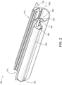
FIG. 2 andFIG. 3 depict exemplary SMFIIMs mounted on an exemplary light curtain housing. A longitudinal light curtain housing andindicator assembly 200 is depicted. AnSMFIIM 120 is mounted on each side of alight curtain housing 210 along alongitudinal axis 205. Thelight curtain housing 210 may, for example, be constructed as an extrusion. Thelight curtain housing 210 may, for example, include plastic. Thelight curtain housing 210 may, for example, include aluminum. - The
light curtain housing 210 is provided with a longitudinally extending aperture 215 (having a width as shown). Thelongitudinally extending aperture 215 defines an opening into acavity 240 defined by thelight curtain housing 210. Light curtain circuitry may, for example, be disposed in the cavity240 and/or thelongitudinally extending aperture 215. - Each of the
SMFIIM 120 is mounted substantially parallel to the longitudinal axis of thelight curtain housing 210. TheSMFIIM 120 includes abase 220. To thebase 220 is coupled acover 225. Thecover 225 may, for example, be at least partially optically translucent. Thecover 225 may, for example, be glowing and refracting light into a wide angle. - The
SMFIIM 120 is provided with a longitudinally extending mountingmember 230. The mountingmember 230 extends substantially perpendicularly away from a surface of theSMFIIM 120 configured to face thelight curtain housing 210. The longitudinally extending mountingmember 230 releasably couples within alongitudinally extending channel 235 in thelight curtain housing 210. Accordingly, theSMFIIM 120 is releasably coupled to thelight curtain housing 210. - As depicted in
FIG. 3 , theSMFIIM 120 includes acircuit board 305. Thecircuit board 305 may, for example, include at least one light-emitting element. In some embodiments thecircuit board 305 may, for example, include at least one array of light-emitting elements. The light-emitting elements may, for example, include light-emitting diodes (LEDs). The array(s) of light-emitting elements may, for example, include linear arrays. The arrays may, for example, extend longitudinally along the circuit board such that, when theSMFIIM 120 is coupled to the 210, the arrays are oriented substantially parallel to the longitudinal axis of thelight curtain housing 210. - In the depicted example, the
cover 225 is a unitary housing. The unitary housing may, for example, be formed as a linear extrusion. Thecover 225 includes mounting features 310. The mounting features may, for example, releasably couple to thecircuit board 305. In the depicted example, the mounting features are arranged such that anoptical axis 312 of the light-emitting elements of thecircuit board 305 is oriented at an angle α relative to aplane 314 tangential to a mounting surface of thelight curtain housing 210. The α, as depicted, may be less than 90 degrees. Accordingly, theSMFIIM 120 may, by way of example and not limitation, be advantageously mounted on a side of thelight curtain housing 210 while still being visible from a front of thelight curtain housing 210. (e.g., from an optical axis along an emission plane of the light curtain, extending from a center of thelight curtain housing 210 through a center of the width of thelongitudinally extending aperture 215 and substantially parallel to the longitudinal axis. - The longitudinally extending mounting
member 230 includes arib 315 extending longitudinally. Therib 315 extends distally away from a mounting surface of thecover 225. The longitudinally extending mountingmember 230 may, for example, be a retention member configured to be inserted into thelongitudinally extending channel 235. The longitudinally extending mountingmember 230 may, for example, be configured to assemble to thelight curtain housing 210 in response to application of a force perpendicular to a tangential of a surface of thelight curtain housing 210. In the depicted example, adistal coupling member 320 is provided, extending longitudinally along a distal end of therib 315. - The longitudinally extending mounting
member 230 is configured to releasably couple to thelongitudinally extending channel 235. Thelongitudinally extending channel 235 includes an opening 325. The opening 325 may, for example, have a width W (e.g., 2 mm, 5mm, 10 mm, 20 mm, 30 mm, wider). The opening 325 may transition to a restriction 330 having a width W1 < W. The restriction 330 may open into a channel 335 having a width (e.g., diameter) W2 > W > W1. Thedistal coupling member 320 may, for example, be configured to be releasably captured within the 335. Thedistal coupling member 320 may, for example, be configured to be (substantially elastically) compressed to pass through the 330 when inserted radially thereinto and then expand (e.g., substantially elastically) once within the channel 335. Accordingly, theSMFIIM 120 may be advantageously coupled to thelight curtain housing 210 by the longitudinally extending mountingmember 230 engaging thelongitudinally extending channel 235. - The longitudinally extending mounting
member 230 may, for example, prevent rotation of theSMFIIM 120 relative to thelight curtain housing 210. Accordingly, for example, a user may advantageously position the lights freely up or down along a longitudinal axis of thelight curtain housing 210. -
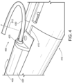
FIG. 4 shows an exemplary SMFIIM mounted on an exemplary light curtain housing. An exemplary side-indicatorlight curtain system 400 includes anSMFIIM 405 mounted on alight curtain 410. Thelight curtain 410 includes alongitudinally extending channel 415. TheSMFIIM 405 is releasably coupled to thelight curtain 410 by insertion of a retaining member (not shown) (e.g., such as the rib 315) into thelongitudinally extending channel 415. - The
SMFIIM 405 includes a unitarylinear extrusion body 420 coupled to abase 425. Light-emitting elements (not shown) of theSMFIIM 405 are provided power and/or command signals by a cable 430 (e.g., coupled to thelight curtain 410, coupled to a separate power and/or command source). As depicted, a fastening member (e.g., screw) may be inserted through the base 425 to engage thelongitudinally extending channel 415. The fastening member may, for example, prevent movement of theSMFIIM 405 along the longitudinal axis relative to thelight curtain 410. -
FIG. 5 andFIG. 6 depict an exemplary SMFIIM deployed in an exemplary use-case scenario. As shown inFIG. 5 , twoSMFIIMs 120 are mounted on thelight curtain unit 110. In this example, theSMFIIMs 120 are connected to acentral hub 505 for control. In thisscenario 500, a first indication 510 (e.g., the light curtain is not armed, and workers can pass through) is displayed at theSMFIIMs 120. As shown inFIG. 6 , ascenario 600 indicates that asecond indication 605 is displayed at theSMFIIMs 120. For example, thesecond indication 605 may indicate that a machine behind the light curtain is armed. For example, it may be hazardous to pass through thelight curtain 110 at this time. -
FIG. 7 depicts exemplary different types of cascaded side-mounted field-installable modules (CSMFIMs) depicted in an illustrative use-case scenario 700. In this example, thelight curtain unit 110 is mounted with theSMFIIM 120, a side mounted input module (SMIM 705), and a side mounted sensing module (SMSM 710). As shown, theSMFIIM 120, theSMIM 705, and theSMSM 710 are serially connected to thelight curtain unit 110. For example, theSMFIIM 120, theSMIM 705, and theSMSM 710 may receive power from thelight curtain unit 110 cascadingly. In some implementations, theSMFIIM 120, theSMIM 705, and theSMSM 710 may be parallelly connected to a hub (for electrical power, control). - The
SMIM 705 includes aninput interface 715. For example, theinput interface 715 may be a touch input (e.g., a capacitive touch input). For example, theinput interface 715 may include push buttons. Theinput interface 715 may, for example, include sliding inputs. In some implementations, a user may use theinput interface 715 to, for example, control thelight curtain unit 110, theSMFIIM 120, themachine 105, or a combination thereof. - The
SMSM 710 includessensors 720. Thesensors 720 may, for example, include light sensors. Thesensors 720 may, for example, include temperature sensors. Thesensors 720 may, for example, include distance sensors (e.g., a very low range time-of-flight sensor). In some implementations, the distance sensors may detect whether an object (e.g., a person, vehicles, other moving objects) is getting too close to possibly break the curtain oflight 115. For example, thesensors 720 may transmit a signal to trigger theSMFIIM 120 to display (e.g., in changing the indication from green to amber) to advantageously provide an early warning before the curtain oflight 115 is broken. For example, the early warning may advantageously prevent unnecessarily shutting down of themachine 105, causing production delays. In various implementations, the CSMFIM may advantageously provide a cost effective way to provide customizable functionality to thelight curtain unit 110. -
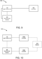
FIG. 8 ,FIG. 9, and FIG. 10 are block diagrams showing exemplary control circuits of exemplary side mounted modules. As shown inFIG. 8 , acontrol system 800 includes thelight curtain unit 110 and a side mountedmodule 805. Thelight curtain unit 110 is mechanically coupled to the side mountedmodule 805. The side mountedmodule 805 includes an indicator 810 (e.g., the SMFIIM 120), a touch input 815 (e.g., the SMIM 705), and sensors 820 (e.g., the SMSM 710). For example, the side mountedmodule 805 may be mounted to thelight curtain unit 110 using mechanisms as described with reference toFIGS. 2-6 . - In this example, the
light curtain unit 110 and the side mountedmodule 805 are operably coupled to acontroller 825. For example, thecontroller 825 may be a safety control network. For example, thecontroller 825 may be a network controlled by a safety PLC. In this example, thecontroller 825 may control both thelight curtain unit 110 and the side mountedmodule 805. For example, thecontroller 825 may control the color of theindicator 810 based on a status of thelight curtain unit 110. In some implementations, thecontroller 825 may also receive input (e.g., sensor input) from the side mountedmodule 805 and operate thelight curtain unit 110 based on the received input (e.g., mute or arm the light curtain unit 110). - As shown in
FIG. 9 , the side mountedmodule 805 is connected to thelight curtain unit 110 mechanically and operably. For example, theindicator 810 may be operated with an output signal switching device (OSSD) signal wire of thelight curtain unit 110. - As shown in
FIG.10 , acontrol system 1000 includes twoindependent controllers light curtain unit 110 is connected to thecontroller 1005a. The side mountedmodule 805 is connected to thecontroller 1005b. As such, thelight curtain unit 110 and the side mountedmodule 805 are coupled mechanically. For example, thelight curtain unit 110 and the side mountedmodule 805 are controlled independently. In this example, thecontrollers network 1010. For example, thenetwork 1010 may coordinate smart customer applications with thecontrollers - Although various embodiments have been described with reference to the figures, other embodiments are possible. Although an exemplary system has been described with reference to the figures, other implementations may be deployed in other industrial, scientific, medical, commercial, and/or residential applications.
- In some embodiments a system for a lighting bar may be designed for a wide-viewing angle. The system may, for example, include a lighting bar configurable to be removably attached by a user to a light curtain at a user-defined location.
- Some embodiments may, for example, provide a method of providing illumination to a light curtain by releasably attaching a SMFIIM to it by applying an insertion force to the SMFIIM substantially perpendicular to a channel of the light curtain.
- In some embodiments, a retention member of the SMFIIM may, for example, be replaceable (e.g., interchangeable for different sizes). In some embodiments a retention member of the SMFIIM may, for example, include a channel. The channel may, for example, releasably engage a rib. The rib may, for example, be releasably coupled to the light curtain. The rib may, for example, be integrally formed with the light curtain.
- In some embodiments the SMFIIM may, for example, be configured to couple to a linear measuring device (e.g., measuring light curtain). In some embodiments the SMFIIM may, for example, be configured to releasably couple to linear extrusion (e.g., standard aluminum extrusions).
- In various safety light curtain applications, highly visible indication of the light curtain status may be desirable. The highly visible indicators can be used to quickly and/or easily determine a status of the light curtain and/or minimize downtime of the guarded machine. In some cases, the indicators may be used to display information other than (e.g., in additional to, instead of) the light curtain status, such as a status of a warehouse floor. In various examples, the indicators need to be visible to personnel from a variety of angles and positions.
- Various embodiments may include field-installable strip lights mounted to one or more sides of a safety light curtain sensor to provide bright illumination of an indication. The indication may, for example, correspond to a light curtain, warehouse, and/or machine status. The lights may be controlled directly by the light curtain. The lights may be controlled externally by a separate controller.
- In some embodiments, internal printed circuit boards (PCBs) may, for example, be angled at approximately 45° to provide viewing from a variety of angles (e.g., α may be substantially 45°). In some embodiments an entire, molded plastic extrusion may be illuminated. Such embodiments may, for example, provide excellent viewing from multiple angles. For example, in some such embodiments, an emitted indication may be visible even from behind the light curtain.
- In various embodiments, some bypass circuits implementations may be controlled in response to signals from analog or digital components, which may be discrete, integrated, or a combination of each. Some embodiments may include programmed, programmable devices, or some combination thereof (e.g., PLAs, PLDs, ASICs, microcontroller, microprocessor), and may include one or more data stores (e.g., cell, register, block, page) that provide single or multi-level digital data storage capability, and which may be volatile, non-volatile, or some combination thereof. Some control functions may be implemented in hardware, software, firmware, or a combination of any of them.
- Although an example of a system, which may be portable, has been described with reference to the above figures, other implementations may be deployed in other processing applications, such as desktop and networked environments.
- Temporary auxiliary energy inputs may be received, for example, from chargeable or single use batteries, which may enable use in portable or remote applications. Some embodiments may operate with other DC voltage sources, such as batteries, for example. Alternating current (AC) inputs, which may be provided, for example from a 50/60 Hz power port, or from a portable electric generator, may be received via a rectifier and appropriate scaling. Provision for AC (e.g., sine wave, square wave, triangular wave) inputs may include a line frequency transformer to provide voltage step-up, voltage step-down, and/or isolation.
- In various implementations, the system may communicate using suitable communication methods, equipment, and techniques. For example, the system may communicate with compatible devices (e.g., devices capable of transferring data to and/or from the system) using point-to-point communication in which a message is transported directly from the source to the receiver over a dedicated physical link (e.g., fiber optic link, point-to-point wiring, daisy-chain). The components of the system may exchange information by any form or medium of analog or digital data communication, including packet-based messages on a communication network. Examples of communication networks include, e.g., a LAN (local area network), a WAN (wide area network), MAN (metropolitan area network), wireless and/or optical networks, the computers and networks forming the Internet, or some combination thereof. Other implementations may transport messages by broadcasting to all or substantially all devices that are coupled together by a communication network, for example, by using omni-directional radio frequency (RF) signals. Still other implementations may transport messages characterized by high directivity, such as RF signals transmitted using directional (i.e., narrow beam) antennas or infrared signals that may optionally be used with focusing optics. Still other implementations are possible using appropriate interfaces and protocols such as, by way of example and not intended to be limiting, USB 2.0, Firewire, ATA/IDE, RS-232, RS-422, RS-485, 802.11 a/b/g, Wi-Fi, Ethernet, IrDA, FDDI (fiber distributed data interface), token-ring networks, multiplexing techniques based on frequency, time, or code division, or some combination thereof. Some implementations may optionally incorporate features such as error checking and correction (ECC) for data integrity, or security measures, such as encryption (e.g., WEP) and password protection.
- In various embodiments, the computer system may include Internet of Things (IoT) devices. IoT devices may include objects embedded with electronics, software, sensors, actuators, and network connectivity which enable these objects to collect and exchange data. IoT devices may be in-use with wired or wireless devices by sending data through an interface to another device. IoT devices may collect useful data and then autonomously flow the data between other devices.
- Various examples of modules may be implemented using circuitry, including various electronic hardware. By way of example and not limitation, the hardware may include transistors, resistors, capacitors, switches, integrated circuits, other modules, or some combination thereof. In various examples, the modules may include analog logic, digital logic, discrete components, traces and/or memory circuits fabricated on a silicon substrate including various integrated circuits (e.g., FPGAs, ASICs), or some combination thereof. In some embodiments, the module(s) may involve execution of preprogrammed instructions, software executed by a processor, or some combination thereof. For example, various modules may involve both hardware and software.
- A number of implementations have been described. Nevertheless, it will be understood that various modifications may be made. For example, advantageous results may be achieved if the steps of the disclosed techniques were performed in a different sequence, or if components of the disclosed systems were combined in a different manner, or if the components were supplemented with other components. Accordingly, other implementations may be contemplated within the scope of the following claims.
Claims (9)
- A light curtain status indicator (120), comprising:a light emitting module (305) comprising a refractive cover (225) and configured to emit a visual indicium (125) at a wide angle corresponding to a status of at least one predetermined signal, wherein the wide angle comprises a viewing angle of at least 180°; characterized bya coupling member (230) configured to be releasably captured within a longitudinally extending channel (235) of a housing of a light curtain (110), such that the light curtain status indicator is coupled to the housing to be disposed on a side of and substantially parallel to the housing,wherein the light emitting module is configured to emit the visual indicium in an emitting plane (314) intersecting an optical axis (312) of the light curtain, and,when the light curtain status indicator is releasably coupled to the housing, the emitting plane is oriented at an angle α relative to a plane tangential to a mounting surface of the light curtain housing, and α < 90°, such that the light emitting module is viewable from the wide angle.
- The light curtain status indicator of claim 1 or the safety system of claim 8, wherein the light emitting module comprises a longitudinally extending array of light emitters configured such that, when the light curtain status indicator is releasably coupled to the housing of the light curtain, the array of light emitters extends substantially parallel to the housing.
- The light curtain status indicator of claim 1 or the safety system of claim 8, wherein the coupling member is releasably captured within the longitudinally extending channel such that the light curtain status indicator is slidably adjustable relative to the housing.
- The light curtain status indicator of claim 1 or the safety system of claim 8, further comprising a cascading electrical port configured to serially electrically connect to other field-installable side mounted devices.
- The light curtain status indicator or the safety system of claim 4, wherein the other field-installable side mounted device comprises another light curtain status indicator.
- The light curtain status indicator of claim 1 or the safety system of claim 8, further comprising a touch input device.
- The light curtain status indicator of claim 1 or the safety system of claim 8, further comprising a sensor device.
- A safety system comprising:a light curtain (110) configured to detect an approaching object towards a manufacturing area; and,at least one light curtain status indicator (120) according to claim 1 configured to be releasably coupled to the light curtain.
- The safety system of claim 8, wherein when two status indicators are releasably coupled to the light curtain, the visual indicium emitted by the status indicators are visible 360° around the housing of the light curtain.
Applications Claiming Priority (2)
| Application Number | Priority Date | Filing Date | Title |
|---|---|---|---|
| US202163260728P | 2021-08-30 | 2021-08-30 | |
| PCT/US2022/075677 WO2023034807A1 (en) | 2021-08-30 | 2022-08-30 | Field installable light curtain side status module |
Publications (3)
| Publication Number | Publication Date |
|---|---|
| EP4377723A1 EP4377723A1 (en) | 2024-06-05 |
| EP4377723C0 EP4377723C0 (en) | 2025-05-14 |
| EP4377723B1 true EP4377723B1 (en) | 2025-05-14 |
Family
ID=85287817
Family Applications (1)
| Application Number | Title | Priority Date | Filing Date |
|---|---|---|---|
| EP22790156.8A Active EP4377723B1 (en) | 2021-08-30 | 2022-08-30 | Field installable light curtain side status module |
Country Status (3)
| Country | Link |
|---|---|
| US (1) | US11854377B2 (en) |
| EP (1) | EP4377723B1 (en) |
| CN (1) | CN118043704A (en) |
Families Citing this family (1)
| Publication number | Priority date | Publication date | Assignee | Title |
|---|---|---|---|---|
| US20080135083A1 (en) * | 2006-12-08 | 2008-06-12 | Higher Way Electronic Co., Ltd. | Cascade solar cell with amorphous silicon-based solar cell |
Family Cites Families (22)
| Publication number | Priority date | Publication date | Assignee | Title |
|---|---|---|---|---|
| US5302942A (en) | 1992-11-19 | 1994-04-12 | Scientific Technologies Incorporated | Light curtain system with individual beam indicators and method of operation |
| DE59705191D1 (en) | 1997-06-30 | 2001-12-06 | Cedes Ag Landquart | Photo eye or light curtain with alignment aid |
| JP4052608B2 (en) | 1998-06-02 | 2008-02-27 | 株式会社キーエンス | Multi-optical axis photoelectric switch |
| DE60041041D1 (en) | 1999-03-11 | 2009-01-22 | Omron Scientific Technologies Inc | MODULAR SWIVEL LIGHT BARRIER |
| JP3724397B2 (en) * | 2000-08-09 | 2005-12-07 | オムロン株式会社 | Multi-axis photoelectric sensor |
| JP2003057360A (en) | 2001-08-09 | 2003-02-26 | Keyence Corp | Multiple optical axis photoelectric safety device |
| US6710325B2 (en) * | 2001-12-20 | 2004-03-23 | Dynapar Corporation | Light curtain mounting system wherein housing and mounting bracket include curved surfaces |
| DE10308285A1 (en) * | 2003-02-26 | 2004-09-09 | Sick Ag | Optical transmission and reception arrangement |
| JP4839805B2 (en) * | 2005-11-30 | 2011-12-21 | オムロン株式会社 | Sensor device |
| CN201895235U (en) * | 2010-11-19 | 2011-07-13 | 上海中护电子有限公司 | Safety light curtain sensor capable of omnidirectional displaying |
| EP2511737B1 (en) | 2011-04-13 | 2021-09-15 | Rockwell Automation Switzerland GmbH | Modular light curtain and plug-in module therefor |
| CN202032272U (en) * | 2011-04-18 | 2011-11-09 | 宁波泰德光电有限公司 | Safety light curtain protective device |
| EP2660629B1 (en) | 2012-05-02 | 2014-11-26 | Cedes Safety & Automation AG | Optical module and optical unit for a light curtain, and fabrication method |
| EP3051320B1 (en) * | 2015-01-28 | 2018-11-28 | Rockwell Automation Safety AG | Cascading of optical units of a light curtain |
| US9671523B2 (en) | 2015-08-05 | 2017-06-06 | Banner Engineering Corp. | Field installable light curtain status module |
| CN206876904U (en) | 2017-05-22 | 2018-01-12 | 山东莱恩光电科技有限公司 | All standing light curtain |
| JP7021348B2 (en) | 2017-11-30 | 2022-02-16 | ライカ バイオシステムズ イメージング インコーポレイテッド | Safety light curtain that disables the rotation of the carousel |
| CN211402786U (en) * | 2019-11-06 | 2020-09-01 | 广州安协科技股份有限公司 | Correlation light curtain with optical axis state indicating device |
| CN211856941U (en) * | 2020-03-05 | 2020-11-03 | 广州安协科技股份有限公司 | Correlation light curtain and detection system |
| CN213126041U (en) * | 2020-09-03 | 2021-05-04 | 周伟 | Intelligent synchronous light curtain |
| US11346498B1 (en) | 2021-01-27 | 2022-05-31 | Rockwell Automation Technologies, Inc. | Light curtain alignment using beam intensities |
| CN113256798B (en) * | 2021-06-04 | 2023-05-05 | 猫岐智能科技(上海)有限公司 | Light curtain shielding region generation system and method |
-
2022
- 2022-08-30 CN CN202280059398.9A patent/CN118043704A/en active Pending
- 2022-08-30 US US17/823,312 patent/US11854377B2/en active Active
- 2022-08-30 EP EP22790156.8A patent/EP4377723B1/en active Active
Also Published As
| Publication number | Publication date |
|---|---|
| EP4377723C0 (en) | 2025-05-14 |
| US20230064404A1 (en) | 2023-03-02 |
| CN118043704A (en) | 2024-05-14 |
| US11854377B2 (en) | 2023-12-26 |
| EP4377723A1 (en) | 2024-06-05 |
Similar Documents
| Publication | Publication Date | Title |
|---|---|---|
| EP1175579B1 (en) | Diffuse reflective light curtain system | |
| US20170228991A1 (en) | Field installable light curtain status module | |
| US9764474B2 (en) | Robot system in which brightness of installation table for robot is changed | |
| US9200955B2 (en) | Multi-optical-axis photoelectric sensor having an inter-optical-axis indication unit | |
| US9599748B2 (en) | Multi-optical axis photoelectric sensor | |
| JPH11345548A (en) | Method for displaying state of multi-optical-axis photoelectric switch and multi-optical-axis photoelectric switch | |
| EP3901513B1 (en) | Safety switch and switch system | |
| US11854377B2 (en) | Field installable light curtain side status module | |
| EP3889981B1 (en) | Control system for electrically controlled installations | |
| JP5229902B2 (en) | Safe position detector with intrusion detection function | |
| EP3462216A1 (en) | Optoelectronic sensor having plug-in unit for providing extended functionality | |
| WO2023034807A1 (en) | Field installable light curtain side status module | |
| US20140239162A1 (en) | Switch | |
| KR20230034105A (en) | Floor traffic light device and error handling method thereof | |
| US10649431B2 (en) | Control system for electrically controlled installations | |
| EP2218958B1 (en) | Method and apparatus for determining an overtravel time of a machine | |
| JP2007235408A (en) | Multi-optical axis photoelectric safety device and control method thereof | |
| US12242012B2 (en) | Field installable laser alignment tool | |
| JP4460486B2 (en) | Multi-optical axis photoelectric safety device | |
| EP4418056B1 (en) | Operating unit and method for operating a system with an operating unit | |
| US20240102641A1 (en) | Industrial luminaire | |
| ITTO20090147A1 (en) | SAFETY BARRIER WITH LIGHT DETECTION | |
| US20060044135A1 (en) | Apparatus and method for collision avoidance | |
| CN222466378U (en) | A mobile cabinet and human body protection system thereof | |
| WO2023019051A1 (en) | Field installable laser alignment tool |
Legal Events
| Date | Code | Title | Description |
|---|---|---|---|
| STAA | Information on the status of an ep patent application or granted ep patent |
Free format text: STATUS: UNKNOWN |
|
| STAA | Information on the status of an ep patent application or granted ep patent |
Free format text: STATUS: THE INTERNATIONAL PUBLICATION HAS BEEN MADE |
|
| PUAI | Public reference made under article 153(3) epc to a published international application that has entered the european phase |
Free format text: ORIGINAL CODE: 0009012 |
|
| STAA | Information on the status of an ep patent application or granted ep patent |
Free format text: STATUS: REQUEST FOR EXAMINATION WAS MADE |
|
| 17P | Request for examination filed |
Effective date: 20240226 |
|
| AK | Designated contracting states |
Kind code of ref document: A1 Designated state(s): AL AT BE BG CH CY CZ DE DK EE ES FI FR GB GR HR HU IE IS IT LI LT LU LV MC MK MT NL NO PL PT RO RS SE SI SK SM TR |
|
| DAV | Request for validation of the european patent (deleted) | ||
| DAX | Request for extension of the european patent (deleted) | ||
| GRAP | Despatch of communication of intention to grant a patent |
Free format text: ORIGINAL CODE: EPIDOSNIGR1 |
|
| STAA | Information on the status of an ep patent application or granted ep patent |
Free format text: STATUS: GRANT OF PATENT IS INTENDED |
|
| INTG | Intention to grant announced |
Effective date: 20241210 |
|
| GRAS | Grant fee paid |
Free format text: ORIGINAL CODE: EPIDOSNIGR3 |
|
| GRAA | (expected) grant |
Free format text: ORIGINAL CODE: 0009210 |
|
| STAA | Information on the status of an ep patent application or granted ep patent |
Free format text: STATUS: THE PATENT HAS BEEN GRANTED |
|
| AK | Designated contracting states |
Kind code of ref document: B1 Designated state(s): AL AT BE BG CH CY CZ DE DK EE ES FI FR GB GR HR HU IE IS IT LI LT LU LV MC MK MT NL NO PL PT RO RS SE SI SK SM TR |
|
| REG | Reference to a national code |
Ref country code: GB Ref legal event code: FG4D |
|
| REG | Reference to a national code |
Ref country code: CH Ref legal event code: EP |
|
| REG | Reference to a national code |
Ref country code: DE Ref legal event code: R096 Ref document number: 602022014752 Country of ref document: DE |
|
| REG | Reference to a national code |
Ref country code: IE Ref legal event code: FG4D |
|
| U01 | Request for unitary effect filed |
Effective date: 20250521 |
|
| U07 | Unitary effect registered |
Designated state(s): AT BE BG DE DK EE FI FR IT LT LU LV MT NL PT RO SE SI Effective date: 20250528 |
|
| PG25 | Lapsed in a contracting state [announced via postgrant information from national office to epo] |
Ref country code: ES Free format text: LAPSE BECAUSE OF FAILURE TO SUBMIT A TRANSLATION OF THE DESCRIPTION OR TO PAY THE FEE WITHIN THE PRESCRIBED TIME-LIMIT Effective date: 20250514 |
|
| PG25 | Lapsed in a contracting state [announced via postgrant information from national office to epo] |
Ref country code: GR Free format text: LAPSE BECAUSE OF FAILURE TO SUBMIT A TRANSLATION OF THE DESCRIPTION OR TO PAY THE FEE WITHIN THE PRESCRIBED TIME-LIMIT Effective date: 20250815 Ref country code: NO Free format text: LAPSE BECAUSE OF FAILURE TO SUBMIT A TRANSLATION OF THE DESCRIPTION OR TO PAY THE FEE WITHIN THE PRESCRIBED TIME-LIMIT Effective date: 20250814 |
|
| PG25 | Lapsed in a contracting state [announced via postgrant information from national office to epo] |
Ref country code: PL Free format text: LAPSE BECAUSE OF FAILURE TO SUBMIT A TRANSLATION OF THE DESCRIPTION OR TO PAY THE FEE WITHIN THE PRESCRIBED TIME-LIMIT Effective date: 20250514 |
|
| PG25 | Lapsed in a contracting state [announced via postgrant information from national office to epo] |
Ref country code: HR Free format text: LAPSE BECAUSE OF FAILURE TO SUBMIT A TRANSLATION OF THE DESCRIPTION OR TO PAY THE FEE WITHIN THE PRESCRIBED TIME-LIMIT Effective date: 20250514 |
|
| PG25 | Lapsed in a contracting state [announced via postgrant information from national office to epo] |
Ref country code: RS Free format text: LAPSE BECAUSE OF FAILURE TO SUBMIT A TRANSLATION OF THE DESCRIPTION OR TO PAY THE FEE WITHIN THE PRESCRIBED TIME-LIMIT Effective date: 20250814 |
|
| PG25 | Lapsed in a contracting state [announced via postgrant information from national office to epo] |
Ref country code: IS Free format text: LAPSE BECAUSE OF FAILURE TO SUBMIT A TRANSLATION OF THE DESCRIPTION OR TO PAY THE FEE WITHIN THE PRESCRIBED TIME-LIMIT Effective date: 20250914 |
|
| U21 | Renewal fee for the european patent with unitary effect paid with additional fee |
Year of fee payment: 4 Effective date: 20251110 |
|
| PG25 | Lapsed in a contracting state [announced via postgrant information from national office to epo] |
Ref country code: SM Free format text: LAPSE BECAUSE OF FAILURE TO SUBMIT A TRANSLATION OF THE DESCRIPTION OR TO PAY THE FEE WITHIN THE PRESCRIBED TIME-LIMIT Effective date: 20250514 |
|
| PG25 | Lapsed in a contracting state [announced via postgrant information from national office to epo] |
Ref country code: CZ Free format text: LAPSE BECAUSE OF FAILURE TO SUBMIT A TRANSLATION OF THE DESCRIPTION OR TO PAY THE FEE WITHIN THE PRESCRIBED TIME-LIMIT Effective date: 20250514 |
|
| PG25 | Lapsed in a contracting state [announced via postgrant information from national office to epo] |
Ref country code: SK Free format text: LAPSE BECAUSE OF FAILURE TO SUBMIT A TRANSLATION OF THE DESCRIPTION OR TO PAY THE FEE WITHIN THE PRESCRIBED TIME-LIMIT Effective date: 20250514 |
|
| PLBE | No opposition filed within time limit |
Free format text: ORIGINAL CODE: 0009261 |
|
| STAA | Information on the status of an ep patent application or granted ep patent |
Free format text: STATUS: NO OPPOSITION FILED WITHIN TIME LIMIT |
|
| REG | Reference to a national code |
Ref country code: CH Ref legal event code: H13 Free format text: ST27 STATUS EVENT CODE: U-0-0-H10-H13 (AS PROVIDED BY THE NATIONAL OFFICE) Effective date: 20260324 |
|
| REG | Reference to a national code |
Ref country code: CH Ref legal event code: L10 Free format text: ST27 STATUS EVENT CODE: U-0-0-L10-L00 (AS PROVIDED BY THE NATIONAL OFFICE) Effective date: 20260325 |
|
| PG25 | Lapsed in a contracting state [announced via postgrant information from national office to epo] |
Ref country code: MC Free format text: LAPSE BECAUSE OF FAILURE TO SUBMIT A TRANSLATION OF THE DESCRIPTION OR TO PAY THE FEE WITHIN THE PRESCRIBED TIME-LIMIT Effective date: 20250514 |
|
| 26N | No opposition filed |
Effective date: 20260217 |
|
| PG25 | Lapsed in a contracting state [announced via postgrant information from national office to epo] |
Ref country code: CH Free format text: LAPSE BECAUSE OF NON-PAYMENT OF DUE FEES Effective date: 20250831 |