EP4376366A1 - Device and method for channel estimation using short/long-term memory network in millimeter-wave communication system - Google Patents
Device and method for channel estimation using short/long-term memory network in millimeter-wave communication system Download PDFInfo
- Publication number
- EP4376366A1 EP4376366A1 EP22861543.1A EP22861543A EP4376366A1 EP 4376366 A1 EP4376366 A1 EP 4376366A1 EP 22861543 A EP22861543 A EP 22861543A EP 4376366 A1 EP4376366 A1 EP 4376366A1
- Authority
- EP
- European Patent Office
- Prior art keywords
- time slot
- output
- channel
- term memory
- memory network
- Prior art date
- Legal status (The legal status is an assumption and is not a legal conclusion. Google has not performed a legal analysis and makes no representation as to the accuracy of the status listed.)
- Granted
Links
Images


Classifications
-
- H—ELECTRICITY
- H04—ELECTRIC COMMUNICATION TECHNIQUE
- H04B—TRANSMISSION
- H04B17/00—Monitoring; Testing
- H04B17/30—Monitoring; Testing of propagation channels
- H04B17/373—Predicting channel quality or other radio frequency [RF] parameters
-
- H—ELECTRICITY
- H04—ELECTRIC COMMUNICATION TECHNIQUE
- H04L—TRANSMISSION OF DIGITAL INFORMATION, e.g. TELEGRAPHIC COMMUNICATION
- H04L25/00—Baseband systems
- H04L25/02—Details ; arrangements for supplying electrical power along data transmission lines
-
- H—ELECTRICITY
- H04—ELECTRIC COMMUNICATION TECHNIQUE
- H04L—TRANSMISSION OF DIGITAL INFORMATION, e.g. TELEGRAPHIC COMMUNICATION
- H04L25/00—Baseband systems
- H04L25/02—Details ; arrangements for supplying electrical power along data transmission lines
- H04L25/0202—Channel estimation
- H04L25/0224—Channel estimation using sounding signals
-
- H—ELECTRICITY
- H04—ELECTRIC COMMUNICATION TECHNIQUE
- H04L—TRANSMISSION OF DIGITAL INFORMATION, e.g. TELEGRAPHIC COMMUNICATION
- H04L25/00—Baseband systems
- H04L25/02—Details ; arrangements for supplying electrical power along data transmission lines
- H04L25/0202—Channel estimation
- H04L25/024—Channel estimation channel estimation algorithms
- H04L25/0254—Channel estimation channel estimation algorithms using neural network algorithms
Definitions
- the present disclosure relates to a device and method for estimating a channel in a millimeter-wave (mmWave) communication system.
- mmWave millimeter-wave
- mmWave millimeter-wave
- 4GLTE fourth generation long term evolution
- a beamforming scheme through a multiple input multiple output (MIMO) system using a plurality of antennas is used in the mmWave communication system.
- MIMO multiple input multiple output
- a channel coefficient that needs to be estimated in the MIMO system increases in proportion to the number of antennas in a receiver and a transmitter.
- pilot transmission overhead occurs because at least the same number of pilots as the number of channel coefficients need to be transmitted.
- a channel estimation method using a long short-term memory network includes: inputting a received pilot signal of a time slot to a long short-term memory network; extracting a time-varying channel feature embedding vector by estimating a change state of a channel by using the received pilot signal of the time slot as an input in the long short-term memory network; estimating a parameter of a channel model by using the time-varying channel feature embedding vector as an input in a fully connected network; and estimating a channel for the received pilot signal of the time slot, using the parameter of the channel model.
- a receiver includes: a coupling unit configured to obtain a received pilot signal by multiplying a combining matrix by a signal received through an antenna; a channel estimation unit configured to estimate a channel from pilot signals received in units of time slots, using a long short-term memory network and a fully connected network; an equalizer configured to correct a distortion in the pilot signals received in units of time slots; a demodulation unit configured to demodulate the corrected signal; and a decoding unit configured to decode the demodulated signal.
- mmWave millimeter-wave
- FIG. 1 schematically illustrates a configuration of a receiver of a mmWave communication system including a channel estimation device to estimate a channel using a long short-term memory network according to an embodiment.
- the mmWave communication system of the present disclosure may use a geometric channel model.
- a receiver 100 of the mmWave communication system may be configured to include a coupling unit 110, a channel estimation unit 120, an equalizer 130, a demodulation unit 150, and a decoding unit 150.
- the coupling unit 110 may obtain a received pilot signal by multiplying a combining matrix by a signal received through an antenna.
- the channel estimation unit 120 may perform channel estimation from pilot signals received in units of time slots, using a long short-term memory network 122 and a fully connected network 124.
- the equalizer 130 may correct a distortion in the pilot signals received in units of time slots.
- the demodulation unit 140 may convert a corrected signal into a discrete signal through a demodulation process.
- the channel estimation unit 120 may be configured to include the long short-term memory network 122, the fully connected network 124, and a channel reproduction unit 126.
- the long short-term memory network 122 may extract a time-varying channel feature embedding vector by estimating a change state of a channel by using the received pilot signal of the time slot as an input.
- the long short-term memory network 122 will be further described below with reference to FIG. 2 .
- the fully connected network 124 may estimate a parameter of a channel model by using the time-varying channel feature embedding vector as an input.
- the parameter of the channel model may include a departure angle, an arrival angle, a path delay, and a path gain.
- the fully connected network 124 will be further described below with reference to FIG. 3 .
- the channel reproduction unit 126 may estimate a channel for the received pilot signal of the time slot, using the parameter of the channel model.
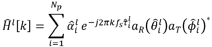
- the channel reproduction unit 126 may estimate a channel by applying the parameter of the channel model to Equation 1 shown below.
- ⁇ l [ k ] denotes an estimated channel matrix of a k -th subcarrier
- ⁇ ⁇ i l denotes an estimated channel gain of an i -th path in an l -th time slot
- f s denotes a spacing between subcarriers
- ⁇ ⁇ i l denotes an estimated path delay of the i -th path in the l -th time slot
- ⁇ ⁇ i l denotes an estimated arrival angle of the i -th path in the l -th time slot
- ⁇ ⁇ i l denotes an estimated departure angle of the i -th path in the l -th time slot
- a R ⁇ ⁇ i l denotes a steering vector for the estimated departure angle of the i -th path in the l -th time slot
- a T ⁇ ⁇ i l denotes a steering vector for the estimated arrival angle of the i -th
- Equation 1 A process of deriving Equation 1 is described below.
- a transmitter may include "N T " antennas and “N RF " RF chains, and may transmit "M” pilot training symbols in total.
- a pilot signal s m [ k ] may be transmitted by multiplying a k -th subcarrier of an m -th symbol by a pre-coding matrix F m .
- the receiver 100 may be assumed to include " N R " antennas and "N RF " RF chains.
- H [ k ] denotes a channel matrix corresponding to a k -th subcarrier in a frequency domain
- F m denotes a precoding matrix of an m -th symbol
- s m [ k ] denotes a pilot signal of the k -th subcarrier of the m -th symbol in the frequency domain
- v m [ k ] denotes noise of the k -th subcarrier of the m -th symbol in the frequency domain.
- the coupling unit 110 of the receiver 100 may obtain a combined signal y m [ k ] by multiplying the received signal r m [ k ] by a combiner matrix W m . Accordingly, a final received signal y m [ k ] in the frequency domain may be expressed as shown in Equation 3 below.
- y m k W m ⁇ H k F m s m k + W m ⁇ v m k
- W m ⁇ denotes a transpose conjugate matrix of a combiner matrix
- H [ k ] denotes a channel matrix corresponding to a k -th subcarrier in a frequency domain
- F m denotes a precoding matrix of an m -th symbol
- s m [ k ] denotes a pilot signal of the k -th subcarrier of the m -th symbol in the frequency domain
- v m [ k ] denotes noise of the k-th subcarrier of the m -th symbol in the frequency domain.
- a channel matrix H ( ⁇ ) in a time domain may be configured as shown in Equation 4 below.
- N p denotes the number of channel paths
- ⁇ i denotes a channel gain of an i- th path
- ⁇ i denotes a path delay of the i -th path
- ⁇ i denotes an arrival angle of the i -th path
- ⁇ i denotes a departure angle of the i -th path.
- a R and a T denote steering vectors defined as shown in Equation 5 below.
- H ( ⁇ ) of the time domain through the channel matrix H [ k ] of the k -th subcarrier may be calculated from Fourier transform. Accordingly, H [ k ] may be expressed as shown in Equation 6 below.
- H [ k ] denotes an estimated channel matrix of a k -th subcarrier
- ⁇ i denotes a channel gain of an i -th path
- f s denotes a spacing between subcarriers
- ⁇ i denotes a path delay of the i -th path
- ⁇ i denotes an arrival angle of the i -th path
- ⁇ i denotes a departure angle of the i -th path
- a R ( ⁇ i ) denotes a steering vector for the departure angle of the i -th path
- a T ( ⁇ i ) denotes a steering vector for the arrival angle of the i -th path.
- Equation 1 may be derived from Equation 6.
- the channel estimation unit 120 with an artificial intelligence neural network structure proposed in the present document may be trained by an Adam optimization algorithm, to minimize a loss function.
- ⁇ l [ k ] denotes a channel matrix corresponding to a k -th subcarrier and an estimated l -th time slot.
- an input y of a long short-term memory network may be generated by concatenating them.
- the input y of the network may be expressed as shown in Equation 8 below by concatenating the " M " training pilot symbols.
- y m [ y m [0] T , y m [1] T , ⁇ , y m [k] T , ⁇ y m [ K - 1] T ] T is satisfied, which indicates a collection of all received signals for " K " subcarriers in an m -th training symbol.
- inputs y corresponding to L times are called y 1 , y 2 , ⁇ , y l , ⁇ , y L in an order. Since an l -th input y l is a complex number, it may be converted into a real number and input to the long short-term memory network 122.
- FIG. 2 illustrates a configuration of a long short-term memory network in a channel estimation device according to an embodiment.
- the long short-term memory network 122 may include a forget gate F C 201, an input gate I C 202, an output gate O C 203, and hyperbolic tangents tanh 204 and 208.
- the long short-term memory network 122 may calculate an output of the input gate 202 that determines a degree to which a candidate state information cell is reflected in a final state information cell based on a received pilot signal of a time slot and an output of the long short-term memory network of a previous time slot.
- the long short-term memory network 122 may calculate an output of the output gate 203 that determines a degree to which the final state information cell is reflected in an output of the long short-term memory network based on the received pilot signal of the time slot and the output of the long short-term memory network of the previous time slot.
- the output of the output gate 203 may be calculated as shown in Equation 11 below.
- FIG. 3 illustrates a configuration of a fully connected network in a channel estimation device according to an embodiment.
- the output x 0 of the input layer 310 is input to "N hidden " hidden layers 320.
- the hidden layer 320 may output a value calculated by Equation 16 shown below.
- x i f activation W i x i ⁇ 1 + b i
- x i denotes an output of an i -th hidden layer
- W i denotes a weight of the i -th hidden layer
- b i denotes a deviation of the i -th hidden layer
- f activation denotes an activation function used in each hidden layer.
- the output layer 330 may output a value calculated by Equation 17 shown below.
- ⁇ l tanh W out x N hidden + b out
- ⁇ l denotes a final output that yields estimates of a departure angle, an arrival angle, a path delay, and a path gain for each channel path in an l -th time slot
- tanh() denotes a hyperbolic tangent function
- W out denotes a weight of an output layer
- x Nhidden denotes a final output of a hidden layer input to the output layer
- b out denotes a deviation of the output layer.
- ⁇ l corresponds to estimates ⁇ l ⁇ l , ⁇ l , and ⁇ l of the departure angle, the arrival angle, the path delay, and the path gain in the l -th time slot.
- the estimate ⁇ l of the path gain includes a real part ( ⁇ l ) and an imaginary part ( ⁇ l ).
- a channel estimation device inputs a received pilot signal of a time slot to a long short-term memory network in operation 510.
- the received pilot signal of the time slot may be converted into a real number and input to the long short-term memory network.
- the long short-term memory network of the channel estimation device may extract a time-varying channel feature embedding vector by estimating a change state of a channel by using the received pilot signal of the time slot as an input.
- the long short-term memory network may extract the time-varying channel feature embedding vector, using the received pilot signal of the time slot, a final state information cell of the long short-term memory network of a previous time slot, and an output of the long short-term memory network of the previous time slot.
- a fully connected network of the channel estimation device may estimate a parameter of a channel model by using the time-varying channel feature embedding vector as an input.
- the parameter of the channel model may include a departure angle, an arrival angle, a path delay, and a path gain.
- the fully connected network may estimate the parameter of the channel model by matching the time-varying channel feature embedding vector and the parameter of the channel model, using an input layer, at least one hidden layer, and an output layer.
- the channel estimation device may estimate a channel for the received pilot signal of the time slot, using the parameter of the channel model.
- the channel estimation device may perform estimation by applying the parameter of the channel model to Equation 1 described above.
- FIG. 5 illustrates a process of calculating a time-varying channel feature embedding vector in a long short-term memory network of a channel estimation device according to an embodiment.
- the long short-term memory network may calculate an output of an input gate that determines a degree to which a candidate state information cell is reflected in a final state information cell based on a received pilot signal of a time slot and an output of the long short-term memory network of a previous time slot.
- the long short-term memory network may calculate an output of a forget gate that determines a degree to which a final state information cell of the previous time slot is reflected in the final state information cell based on the received pilot signal of the time slot and the output of the long short-term memory network of the previous time slot.
- the long short-term memory network may calculate an output of an output gate that determines a degree to which the final state information cell is reflected in an output of the long short-term memory network based on the received pilot signal of the time slot and the output of the long short-term memory network of the previous time slot.
- the long short-term memory network may calculate the candidate state information cell based on the received pilot signal of the time slot and the output of the long short-term memory network of the previous time slot.
- the long short-term memory network may calculate the final state information cell by adding a value obtained by multiplying the output of the forget gate by the final state information cell of the previous time slot and a value obtained by multiplying the output of the input gate by the candidate state information cell.
Landscapes
- Engineering & Computer Science (AREA)
- Computer Networks & Wireless Communication (AREA)
- Signal Processing (AREA)
- Power Engineering (AREA)
- Artificial Intelligence (AREA)
- Evolutionary Computation (AREA)
- Quality & Reliability (AREA)
- Physics & Mathematics (AREA)
- Electromagnetism (AREA)
- Mobile Radio Communication Systems (AREA)
- Monitoring And Testing Of Transmission In General (AREA)
Abstract
Description
- The present disclosure relates to a device and method for estimating a channel in a millimeter-wave (mmWave) communication system.
- Since a millimeter-wave (mmWave) communication system employs a high frequency band (30 gigahertz (GHz) to 300 GHz) unlike existing fourth generation long term evolution (4GLTE) systems, the propagation of mmWave communication is highly attenuated depending on the distance. To offset such a disadvantage, a beamforming scheme through a multiple input multiple output (MIMO) system using a plurality of antennas is used in the mmWave communication system. Here, a channel coefficient that needs to be estimated in the MIMO system increases in proportion to the number of antennas in a receiver and a transmitter. To use a least square method or a minimum mean square error method that is an existing channel estimation method, in the MIMO system, pilot transmission overhead occurs because at least the same number of pilots as the number of channel coefficients need to be transmitted.
- To reduce the pilot transmission overhead, research is being conducted on channel estimation methods using various schemes such as compressive sensing, MUSIC, deep learning schemes, and the like.
- According to various embodiments disclosed in the present disclosure, a channel may be estimated from pilot signals received in units of time slots, using a long short-term memory network and a fully connected network.
- According to an embodiment, a channel estimation method using a long short-term memory network includes: inputting a received pilot signal of a time slot to a long short-term memory network; extracting a time-varying channel feature embedding vector by estimating a change state of a channel by using the received pilot signal of the time slot as an input in the long short-term memory network; estimating a parameter of a channel model by using the time-varying channel feature embedding vector as an input in a fully connected network; and estimating a channel for the received pilot signal of the time slot, using the parameter of the channel model.
- According to an embodiment, a long short-term memory network configured to, when a received pilot signal of a time slot is input, extract a time-varying channel feature embedding vector by estimating a change state of a channel by using the received pilot signal of the time slot as an input; a fully connected network configured to estimate a parameter of a channel model by using the time-varying channel feature embedding vector as an input; and a channel reproduction unit configured to estimate a channel for the received pilot signal of the time slot, using the parameter of the channel model are included.
- According to an embodiment, a receiver includes: a coupling unit configured to obtain a received pilot signal by multiplying a combining matrix by a signal received through an antenna; a channel estimation unit configured to estimate a channel from pilot signals received in units of time slots, using a long short-term memory network and a fully connected network; an equalizer configured to correct a distortion in the pilot signals received in units of time slots; a demodulation unit configured to demodulate the corrected signal; and a decoding unit configured to decode the demodulated signal.
- According to various embodiments, a device and method for estimating a channel from pilot signals received in units of time slots, using a long short-term memory network and a fully connected network are provided, and accurate parameters may be estimated in a situation in which a communication channel changes over time because a parameter of a geometric channel is estimated in a continuous domain through sequentially received pilot signals. In addition, since the parameters are estimated in a time domain instead of a frequency domain, channels for all subcarriers may be estimated using a geometric channel model and Fourier transform.
-
-
FIG. 1 schematically illustrates a configuration of a receiver of a millimeter-wave (mmWave) communication system including a channel estimation device to estimate a channel using a long short-term memory network according to an embodiment. -
FIG. 2 illustrates a configuration of a long short-term memory network in a channel estimation device according to an embodiment. -
FIG. 3 illustrates a configuration of a fully connected network in a channel estimation device according to an embodiment. -
FIG. 4 illustrates a process of estimating a channel in a channel estimation device according to an embodiment. -
FIG. 5 illustrates a process of calculating a time-varying channel feature embedding vector in a long short-term memory network of a channel estimation device according to an embodiment. - Hereinafter, embodiments will be described in detail with reference to the accompanying drawings. When describing the embodiments with reference to the accompanying drawings, like reference numerals refer to like components and a repeated description related thereto will be omitted.
- Hereinafter, a device and method for channel estimation using a long short-term memory network in a millimeter-wave (mmWave) communication system according to an embodiment of the present disclosure is described in detail with reference to
FIGS. 1 to 5 . -
FIG. 1 schematically illustrates a configuration of a receiver of a mmWave communication system including a channel estimation device to estimate a channel using a long short-term memory network according to an embodiment. - Referring to
FIG. 1 , the mmWave communication system of the present disclosure may use a geometric channel model. - A
receiver 100 of the mmWave communication system may be configured to include acoupling unit 110, achannel estimation unit 120, anequalizer 130, ademodulation unit 150, and adecoding unit 150. - The
coupling unit 110 may obtain a received pilot signal by multiplying a combining matrix by a signal received through an antenna. - The
channel estimation unit 120 may perform channel estimation from pilot signals received in units of time slots, using a long short-term memory network 122 and a fully connectednetwork 124. - The
equalizer 130 may correct a distortion in the pilot signals received in units of time slots. - The
demodulation unit 140 may convert a corrected signal into a discrete signal through a demodulation process. - The
decoding unit 150 may obtain accurate data transmitted by a transmitter, by performing error correction (channel decoding) on a demodulated signal and decoding the demodulated signal. - The
channel estimation unit 120 may be configured to include the long short-term memory network 122, the fully connectednetwork 124, and achannel reproduction unit 126. - When a received pilot signal of a time slot is input, the long short-
term memory network 122 may extract a time-varying channel feature embedding vector by estimating a change state of a channel by using the received pilot signal of the time slot as an input. The long short-term memory network 122 will be further described below with reference toFIG. 2 . - The fully connected
network 124 may estimate a parameter of a channel model by using the time-varying channel feature embedding vector as an input. Here, the parameter of the channel model may include a departure angle, an arrival angle, a path delay, and a path gain. The fully connectednetwork 124 will be further described below with reference toFIG. 3 . - The
channel reproduction unit 126 may estimate a channel for the received pilot signal of the time slot, using the parameter of the channel model. - The
channel reproduction unit 126 may estimate a channel by applying the parameter of the channel model toEquation 1 shown below.
- Here, Ĥl [k] denotes an estimated channel matrix of a k-th subcarrier,


- A process of deriving
Equation 1 is described below. - A transmitter may include "NT" antennas and "NRF" RF chains, and may transmit "M" pilot training symbols in total. Among them, a pilot signal s m [k] may be transmitted by multiplying a k-th subcarrier of an m-th symbol by a pre-coding matrix Fm. The
receiver 100 may be assumed to include "NR " antennas and "NRF" RF chains. - The
receiver 100 receives a signal r m [k] obtained by adding a noise vector v m [k] and passing through a channel H [k] to a pilot signal Fms m [k] transmitted by the transmitter. Therefore, the signal r m [k] in a frequency domain received by thereceiver 100 may be expressed as shown inEquation 2 below.
- Here, H [k] denotes a channel matrix corresponding to a k-th subcarrier in a frequency domain, F m denotes a precoding matrix of an m-th symbol, sm [k] denotes a pilot signal of the k-th subcarrier of the m-th symbol in the frequency domain, and v m [k] denotes noise of the k-th subcarrier of the m-th symbol in the frequency domain.
- The
coupling unit 110 of thereceiver 100 may obtain a combined signal y m [k] by multiplying the received signal r m [k] by a combiner matrix W m. Accordingly, a final received signal y m [k] in the frequency domain may be expressed as shown inEquation 3 below.
- Here,

- In addition, if the geometric channel model is used, a channel matrix H (τ) in a time domain may be configured as shown in Equation 4 below.

- Here, Np denotes the number of channel paths, αi denotes a channel gain of an i-th path, τi denotes a path delay of the i-th path, θi denotes an arrival angle of the i-th path, and φi denotes a departure angle of the i-th path. In addition, aR and aT denote steering vectors defined as shown in Equation 5 below.

- The channel matrix H (τ) of the time domain through the channel matrix H [k] of the k-th subcarrier may be calculated from Fourier transform. Accordingly, H [k] may be expressed as shown in Equation 6 below.

- Here, H [k] denotes an estimated channel matrix of a k-th subcarrier, αi denotes a channel gain of an i-th path, fs denotes a spacing between subcarriers, τi denotes a path delay of the i-th path, θi denotes an arrival angle of the i-th path, φi denotes a departure angle of the i-th path, aR (θi ) denotes a steering vector for the departure angle of the i-th path, and aT (φi ) denotes a steering vector for the arrival angle of the i-th path.
- Therefore,
Equation 1 may be derived from Equation 6. - The
channel estimation unit 120 with an artificial intelligence neural network structure proposed in the present document may be trained by an Adam optimization algorithm, to minimize a loss function. - A loss function of the
channel estimation unit 120 with the artificial intelligence neural network structure may be defined as shown in Equation 7 below.
- Here, Ĥ l [k] denotes a channel matrix corresponding to a k-th subcarrier and an estimated l-th time slot.
- Meanwhile, since "M" training pilot symbols share the same parameters in a time domain, an input y of a long short-term memory network may be generated by concatenating them. In other words, the input y of the network may be expressed as shown in Equation 8 below by concatenating the "M" training pilot symbols.

- Here, ym = [ym [0] T , ym [1] T ,···, ym [k] T, ··· ym [K - 1] T ] T is satisfied, which indicates a collection of all received signals for "K" subcarriers in an m-th training symbol.
- To estimate a channel that changes for a period of L times over time, inputs y corresponding to L times are called y 1, y 2 , ···, y l, ···, y L in an order. Since an l-th input y l is a complex number, it may be converted into a real number and input to the long short-
term memory network 122. - In other words, an input y in of the long short-
term memory network 122 is
-
FIG. 2 illustrates a configuration of a long short-term memory network in a channel estimation device according to an embodiment. - Referring to
FIG. 2 , the long short-term memory network 122 may include a forgetgate F C 201, an input gate IC 202, an output gate OC 203, and hyperbolic tangents tanh 204 and 208. - The long short-
term memory network 122 may calculate an output of theinput gate 202 that determines a degree to which a candidate state information cell is reflected in a final state information cell based on a received pilot signal of a time slot and an output of the long short-term memory network of a previous time slot. Here, the output of theinput gate 202 may be calculated as shown in Equation 9 below.
- Here, I C denotes an output of an input gate, σ denotes a sigmoid function, WI and UI denote weight matrices of the input gate, bI denotes a deviation of the input gate,

- The long short-
term memory network 122 may calculate the forgetgate 201 that determines a degree to which a final state information cell of the previous time slot is reflected in the final state information cell based on the received pilot signal of the time slot and the output of the long short-term memory network of the previous time slot. Here, an output of the forgetgate 201 may be calculated as shown in Equation 10 below.
- Here, FC denotes an output of a forget gate, σ denotes a sigmoid function, WF and UF denote weight matrices of the forget gate, bF denotes a deviation of the forget gate,

- The long short-
term memory network 122 may calculate an output of the output gate 203 that determines a degree to which the final state information cell is reflected in an output of the long short-term memory network based on the received pilot signal of the time slot and the output of the long short-term memory network of the previous time slot. Here, the output of the output gate 203 may be calculated as shown in Equation 11 below.
- Here, O C denotes an output of an output gate, σ denotes a sigmoid function, Wo and Uo denote weight matrices of the output gate, bo denotes a deviation of the output gate,

- The long short-
term memory network 122 may calculate the candidate state information cell based on the received pilot signal of the time slot and the output of the long short-term memory network of the previous time slot, using thehyperbolic tangent 204. Here, the candidate state information cell may be calculated as shown in Equation 12 below.
- Here, C̃ denotes a value of the candidate state information cell, tanh() denotes a hyperbolic tangent function, WC and UC denote weight matrices of the candidate state information cell, bC denotes a deviation of the candidate state information cell,

- The long short-
term memory network 122 may calculate the final state information cell by adding, using anadder 207, a value obtained by multiplying the output of the forgetgate 201 by the final state information cell of the previous time slot using afirst multiplier 205 and a value obtained by multiplying the output of theinput gate 202 by the candidate state information cell using asecond multiplier 206. Here, the final state information cell may be calculated as shown in Equation 13 below.
- Here, C l denotes a value of the final state information cell of an l-th time slot, F C denotes an output of a forget gate, C l-1 denotes a value of the final state information cell of an (l - 1)-th time slot, I C denotes an output of an input gate, and C̃ denotes a value of a candidate state information cell.
- The long short-
term memory network 122 may calculate and output a time-varying channel feature embedding vector by multiplying an output gate by a value obtained by applying thehyperbolic tangent 208 to the final state information cell using athird multiplier 209. Here, the time-varying channel feature embedding vector may be calculated as shown in Equation 14 below.
- Here, z l denotes a time-varying channel feature embedding vector of an l-th time slot, O C denotes an output of an output gate, tanh() denotes a hyperbolic tangent function, and C l denotes a value of the final state information cell of an l-th time slot.
-
FIG. 3 illustrates a configuration of a fully connected network in a channel estimation device according to an embodiment. - Referring to
FIG. 3 , the fully connectednetwork 124 may estimate a parameter of a channel model by matching a time-varying channel feature embedding vector z l and the parameter of the channel model, using aninput layer 310, at least onehidden layer 320, and anoutput layer 330. - The
input layer 310 may function to adjust a time-varying channel feature embedding vector to a dimension of the hiddenlayer 320. - The
input layer 310 may output a value calculated by Equation 15 shown below.
- Here, x 0 denotes an output of an input layer, W 0 denotes a weight matrix of the input layer, b 0 denotes a deviation of the input layer, zl denotes a time-varying channel feature embedding vector that is an output of a long short-term memory network, and factivation denotes an activation function.
- The output x 0 of the
input layer 310 is input to "Nhidden" hidden layers 320. - The
hidden layer 320 may output a value calculated by Equation 16 shown below.
- Here, x i denotes an output of an i-th hidden layer, Wi denotes a weight of the i-th hidden layer, bi denotes a deviation of the i-th hidden layer, and factivation denotes an activation function used in each hidden layer.
- An output xNhidden passing through the hidden
layer 320 with "NF " dimensions in total calculates a channel parameter through an output layer that is the last layer of the fully connected network, which will be described below. - The
output layer 330 may output a value calculated by Equation 17 shown below.
- Here, Ψ l denotes a final output that yields estimates of a departure angle, an arrival angle, a path delay, and a path gain for each channel path in an l-th time slot, tanh() denotes a hyperbolic tangent function, Wout denotes a weight of an output layer, xNhidden denotes a final output of a hidden layer input to the output layer, and bout denotes a deviation of the output layer.
- In other words, Ψ l corresponds to estimates φ̂l θ̂l , τ̂l , and α̂l of the departure angle, the arrival angle, the path delay, and the path gain in the l-th time slot. Here, the estimate α̂l of the path gain includes a real part(α̂l ) and an imaginary part
 (α̂l ).
- Hereinafter, a method according to the present disclosure configured as described above will be described with reference to the drawings.
-
FIG. 4 illustrates a process of estimating a channel in a channel estimation device according to an embodiment. - Referring to
FIG. 4 , a channel estimation device inputs a received pilot signal of a time slot to a long short-term memory network inoperation 510. Here, the received pilot signal of the time slot may be converted into a real number and input to the long short-term memory network. - In
operation 420, the long short-term memory network of the channel estimation device may extract a time-varying channel feature embedding vector by estimating a change state of a channel by using the received pilot signal of the time slot as an input. - In
operation 420, the long short-term memory network may extract the time-varying channel feature embedding vector, using the received pilot signal of the time slot, a final state information cell of the long short-term memory network of a previous time slot, and an output of the long short-term memory network of the previous time slot. An operation of the long short-term memory network will be further described below with reference toFIG. 5 . - In
operation 430, a fully connected network of the channel estimation device may estimate a parameter of a channel model by using the time-varying channel feature embedding vector as an input. Here, the parameter of the channel model may include a departure angle, an arrival angle, a path delay, and a path gain. - In
operation 430, the fully connected network may estimate the parameter of the channel model by matching the time-varying channel feature embedding vector and the parameter of the channel model, using an input layer, at least one hidden layer, and an output layer. - In
operation 440, the channel estimation device may estimate a channel for the received pilot signal of the time slot, using the parameter of the channel model. - In
operation 440, the channel estimation device may perform estimation by applying the parameter of the channel model toEquation 1 described above. -
FIG. 5 illustrates a process of calculating a time-varying channel feature embedding vector in a long short-term memory network of a channel estimation device according to an embodiment. - Referring to
FIG. 5 , inoperation 510, the long short-term memory network may calculate an output of an input gate that determines a degree to which a candidate state information cell is reflected in a final state information cell based on a received pilot signal of a time slot and an output of the long short-term memory network of a previous time slot. - In
operation 520, the long short-term memory network may calculate an output of a forget gate that determines a degree to which a final state information cell of the previous time slot is reflected in the final state information cell based on the received pilot signal of the time slot and the output of the long short-term memory network of the previous time slot. - In
operation 530, the long short-term memory network may calculate an output of an output gate that determines a degree to which the final state information cell is reflected in an output of the long short-term memory network based on the received pilot signal of the time slot and the output of the long short-term memory network of the previous time slot. - In
operation 540, the long short-term memory network may calculate the candidate state information cell based on the received pilot signal of the time slot and the output of the long short-term memory network of the previous time slot. - In
operation 550, the long short-term memory network may calculate the final state information cell by adding a value obtained by multiplying the output of the forget gate by the final state information cell of the previous time slot and a value obtained by multiplying the output of the input gate by the candidate state information cell. - In
operation 560, the long short-term memory network may calculate and output the time-varying channel feature embedding vector by multiplying the output of the output gate by a value obtained by applying a hyperbolic tangent to the final state information cell. - While the embodiments are described with reference to drawings, it will be apparent to one of ordinary skill in the art that various alterations and modifications in form and details may be made in these embodiments without departing from the spirit and scope of the claims and their equivalents. For example, suitable results may be achieved if the described techniques are performed in a different order and/or if components in a described system, architecture, device, or circuit are combined in a different manner and/or replaced or supplemented by other components or their equivalents.
- Therefore, other implementations, other embodiments, and equivalents to the claims are also within the scope of the following claims.
Claims (15)
- A channel estimation method using a long short-term memory network, the channel estimation method comprising:inputting a received pilot signal of a time slot to a long short-term memory network;extracting a time-varying channel feature embedding vector by estimating a change state of a channel by using the received pilot signal of the time slot as an input in the long short-term memory network;estimating a parameter of a channel model by using the time-varying channel feature embedding vector as an input in a fully connected network; andestimating a channel for the received pilot signal of the time slot, using the parameter of the channel model.
- The channel estimation method of claim 1, wherein the parameter of the channel model comprises a departure angle, an arrival angle, a path delay, and a path gain.
- The channel estimation method of claim 1, wherein the received pilot signal of the time slot is converted into a real number and input to the long short-term memory network.
- The channel estimation method of claim 1, wherein the extracting of the time-varying channel feature embedding vector by estimating the change state of the channel by using the received pilot signal of the time slot as the input in the long short-term memory network extracts the time-varying channel feature embedding vector using the received pilot signal of the time slot, a final state information cell of the long short-term memory network of a previous time slot, and an output of the long short-term memory network of the previous time slot in the long short-term memory network.
- The channel estimation method of claim 1, wherein the extracting of the time-varying channel feature embedding vector by estimating the change state of the channel by using the received pilot signal of the time slot as the input in the long short-term memory network comprises:calculating an output of an input gate that determines a degree to which a candidate state information cell is reflected in a final state information cell based on the received pilot signal of the time slot and an output of the long short-term memory network of a previous time slot;calculating an output of a forget gate that determines a degree to which a final state information cell of the previous time slot is reflected in the final state information cell based on the received pilot signal of the time slot and the output of the long short-term memory network of the previous time slot;calculating an output of an output gate that determines a degree to which the final state information cell is reflected in an output of the long short-term memory network based on the received pilot signal of the time slot and the output of the long short-term memory network of the previous time slot;calculating the candidate state information cell based on the received pilot signal of the time slot and the output of the long short-term memory network of the previous time slot;calculating the final state information cell by adding a value obtained by multiplying the output of the forget gate by the final state information cell of the previous time slot and a value obtained by multiplying the output of the input gate by the candidate state information cell; andcalculating and outputting the time-varying channel feature embedding vector by multiplying the output of the output gate by a value obtained by applying a hyperbolic tangent to the final state information cell.
- The channel estimation method of claim 1, wherein the estimating of the parameter of the channel model by using the time-varying channel feature embedding vector as the input in the fully connected network comprises estimating the parameter of the channel model by matching the time-varying channel feature embedding vector and the parameter of the channel model, using an input layer, at least one hidden layer, and an output layer in the fully connected network.
- The channel estimation method of claim 6, wherein the input layer outputs a value calculated by the following equation:

- The channel estimation method of claim 6, wherein the hidden layer outputs a value calculated by the following equation:

- The channel estimation method of claim 6, wherein the output layer outputs a value calculated by the following equation:

- The channel estimation method of claim 1, wherein the estimating of the channel for the received pilot signal of the time slot, using the parameter of the channel model performs estimation by applying the parameter of the channel model to the following equation:


- A channel estimation device using a long short-term memory network, the channel estimation device comprising:a long short-term memory network configured to, when a received pilot signal of a time slot is input, extract a time-varying channel feature embedding vector by estimating a change state of a channel by using the received pilot signal of the time slot as an input;a fully connected network configured to estimate a parameter of a channel model by using the time-varying channel feature embedding vector as an input; anda channel reproduction unit configured to estimate a channel for the received pilot signal of the time slot, using the parameter of the channel model.
- The channel estimation device of claim 11, wherein the received pilot signal of the time slot is converted into a real number and input to the long short-term memory network.
- The channel estimation device of claim 11, wherein the long short-term memory network is configured to extract the time-varying channel feature embedding vector using the received pilot signal of the time slot, a final state information cell of the long short-term memory network of a previous time slot, and an output of the long short-term memory network of the previous time slot in the long short-term memory network.
- The channel estimation device of claim 11, wherein the long short-term memory network is configured to:calculate an output of an input gate that determines a degree to which a candidate state information cell is reflected in a final state information cell based on the received pilot signal of the time slot and an output of the long short-term memory network of a previous time slot;calculate an output of a forget gate that determines a degree to which a final state information cell of the previous time slot is reflected in the final state information cell based on the received pilot signal of the time slot and the output of the long short-term memory network of the previous time slot;calculate an output of an output gate that determines a degree to which the final state information cell is reflected in an output of the long short-term memory network based on the received pilot signal of the time slot and the output of the long short-term memory network of the previous time slot;calculate the candidate state information cell based on the received pilot signal of the time slot and the output of the long short-term memory network of the previous time slot;calculate the final state information cell by adding a value obtained by multiplying the output of the forget gate by the final state information cell of the previous time slot and a value obtained by multiplying the output of the input gate by the candidate state information cell; andcalculate and output the time-varying channel feature embedding vector by multiplying the output of the output gate by a value obtained by applying a hyperbolic tangent to the final state information cell.
- The channel estimation device of claim 11, wherein the fully connected network is configured to estimate the parameter of the channel model by matching the time-varying channel feature embedding vector and the parameter of the channel model, using an input layer, at least one hidden layer, and an output layer in the fully connected network.
Applications Claiming Priority (2)
| Application Number | Priority Date | Filing Date | Title |
|---|---|---|---|
| KR1020210112977A KR102927333B1 (en) | 2021-08-26 | 2021-08-26 | Apparatus and method for channel estimation via long short term memory in millimetre wave communication |
| PCT/KR2022/009832 WO2023027329A1 (en) | 2021-08-26 | 2022-07-07 | Device and method for channel estimation using short/long-term memory network in millimeter-wave communication system |
Publications (3)
| Publication Number | Publication Date |
|---|---|
| EP4376366A1 true EP4376366A1 (en) | 2024-05-29 |
| EP4376366A4 EP4376366A4 (en) | 2024-12-18 |
| EP4376366B1 EP4376366B1 (en) | 2025-10-22 |
Family
ID=85321812
Family Applications (1)
| Application Number | Title | Priority Date | Filing Date |
|---|---|---|---|
| EP22861543.1A Active EP4376366B1 (en) | 2021-08-26 | 2022-07-07 | Device and method for channel estimation using short/long-term memory network in millimeter-wave communication system |
Country Status (4)
| Country | Link |
|---|---|
| US (1) | US20240195662A1 (en) |
| EP (1) | EP4376366B1 (en) |
| KR (1) | KR102927333B1 (en) |
| WO (1) | WO2023027329A1 (en) |
Family Cites Families (7)
| Publication number | Priority date | Publication date | Assignee | Title |
|---|---|---|---|---|
| KR102067114B1 (en) * | 2018-08-22 | 2020-01-16 | 한양대학교 산학협력단 | Deep learning-based beam tracking and prediction method and system for millimeter wave communications |
| CN110890930B (en) * | 2018-09-10 | 2021-06-01 | 华为技术有限公司 | Channel prediction method, related equipment and storage medium |
| KR102154481B1 (en) * | 2020-03-25 | 2020-09-10 | 전남대학교산학협력단 | Apparatus for beamforming massive mimo system using deep learning |
| CN112968847B (en) * | 2021-02-18 | 2022-05-10 | 浙江大学 | A channel estimation method based on deep learning and data pilot assistance |
| US20230412230A1 (en) * | 2021-10-19 | 2023-12-21 | Samsung Electronics Co., Ltd. | Systems, methods, and apparatus for artificial intelligence and machine learning based reporting of communication channel information |
| US12537722B2 (en) * | 2022-08-31 | 2026-01-27 | Samsung Electronics Co., Ltd. | Device for estimating channel in wireless communication system |
| US12470436B2 (en) * | 2023-02-09 | 2025-11-11 | Aira Technologies, Inc. | System and methods for AI-assisted wireless channel prediction and estimation |
-
2021
- 2021-08-26 KR KR1020210112977A patent/KR102927333B1/en active Active
-
2022
- 2022-07-07 WO PCT/KR2022/009832 patent/WO2023027329A1/en not_active Ceased
- 2022-07-07 EP EP22861543.1A patent/EP4376366B1/en active Active
-
2024
- 2024-02-22 US US18/584,561 patent/US20240195662A1/en active Pending
Also Published As
| Publication number | Publication date |
|---|---|
| WO2023027329A1 (en) | 2023-03-02 |
| KR20230030831A (en) | 2023-03-07 |
| US20240195662A1 (en) | 2024-06-13 |
| EP4376366A4 (en) | 2024-12-18 |
| EP4376366B1 (en) | 2025-10-22 |
| KR102927333B1 (en) | 2026-02-19 |
Similar Documents
| Publication | Publication Date | Title |
|---|---|---|
| US8031762B2 (en) | Stream weight estimation and compensation in SIMO/MIMO OFDM receivers | |
| EP1540832B1 (en) | Method for separating interferering signals and computing arrival angles | |
| EP3154231B1 (en) | Doubly-selective channel compensation method, system and related device | |
| EP3817312B1 (en) | Method and apparatus for estimating angle of arrival of signals in wireless communication system | |
| EP2104981B1 (en) | Antenna selection and soft demapping for mimo decoding | |
| US8958287B1 (en) | Systems and methods for directing a beam towards a device in the presence of interference based on reciprocity | |
| US20080008258A1 (en) | Wireless receiving apparatus and method | |
| US11843429B2 (en) | Wireless communication system, wireless communication method, transmitting station device and receiving station device | |
| CN111262803B (en) | Physical layer secure communication method, device and system based on deep learning | |
| EP3780430B1 (en) | Oam multiplexed communication system and inter-mode interference compensation method | |
| CN102497644B (en) | Low complexity orthogonal iterative beam forming method | |
| CN115733530B (en) | Combined pre-coding method for reconfigurable intelligent surface auxiliary millimeter wave communication | |
| US11646772B2 (en) | Wireless communication system, wireless communication method, transmitting station device and receiving station device | |
| CN115967595A (en) | Semi-blind channel estimation method of MIMO-OTFS system | |
| Tao et al. | Symbiotic radio with orthogonal time frequency space modulation over high-mobility channels | |
| US9264082B2 (en) | System and algorithm for multipath mitigation | |
| JP7264260B2 (en) | Wireless communication system, wireless communication method, transmitting station device and receiving station device | |
| EP4376366B1 (en) | Device and method for channel estimation using short/long-term memory network in millimeter-wave communication system | |
| CN102142878A (en) | Method and device for acquiring beam forming weight | |
| CN120223474B (en) | Multipath channel enhancement method and system based on AoA filtering in synaesthesia integrated system | |
| CN101909022A (en) | A transmission method based on non-codebook precoding in time-varying channel | |
| CN102651661B (en) | Interference alignment method in time division-long term evolution (TD-LTE) system | |
| CN119051696A (en) | Large-scale MIMO-OTFS wave beam forming design method based on deep learning | |
| CN119483682A (en) | Hybrid beamforming method based on terahertz massive MIMO-ISAC system | |
| US11870517B2 (en) | Wireless communication system, wireless communication method, transmitting station device and receiving station device |
Legal Events
| Date | Code | Title | Description |
|---|---|---|---|
| STAA | Information on the status of an ep patent application or granted ep patent |
Free format text: STATUS: THE INTERNATIONAL PUBLICATION HAS BEEN MADE |
|
| PUAI | Public reference made under article 153(3) epc to a published international application that has entered the european phase |
Free format text: ORIGINAL CODE: 0009012 |
|
| STAA | Information on the status of an ep patent application or granted ep patent |
Free format text: STATUS: REQUEST FOR EXAMINATION WAS MADE |
|
| 17P | Request for examination filed |
Effective date: 20240222 |
|
| AK | Designated contracting states |
Kind code of ref document: A1 Designated state(s): AL AT BE BG CH CY CZ DE DK EE ES FI FR GB GR HR HU IE IS IT LI LT LU LV MC MK MT NL NO PL PT RO RS SE SI SK SM TR |
|
| DAV | Request for validation of the european patent (deleted) | ||
| DAX | Request for extension of the european patent (deleted) | ||
| A4 | Supplementary search report drawn up and despatched |
Effective date: 20241115 |
|
| RIC1 | Information provided on ipc code assigned before grant |
Ipc: H04B 17/373 20150101ALI20241111BHEP Ipc: H04L 25/02 20060101AFI20241111BHEP |
|
| GRAP | Despatch of communication of intention to grant a patent |
Free format text: ORIGINAL CODE: EPIDOSNIGR1 |
|
| STAA | Information on the status of an ep patent application or granted ep patent |
Free format text: STATUS: GRANT OF PATENT IS INTENDED |
|
| INTG | Intention to grant announced |
Effective date: 20250520 |
|
| RIN1 | Information on inventor provided before grant (corrected) |
Inventor name: AN, YONG JUN Inventor name: SHIM, BYONG HYO Inventor name: KIM, JIN HONG Inventor name: KIM, WON JUN Inventor name: KIM, KYEONGYEON |
|
| GRAS | Grant fee paid |
Free format text: ORIGINAL CODE: EPIDOSNIGR3 |
|
| GRAA | (expected) grant |
Free format text: ORIGINAL CODE: 0009210 |
|
| STAA | Information on the status of an ep patent application or granted ep patent |
Free format text: STATUS: THE PATENT HAS BEEN GRANTED |
|
| AK | Designated contracting states |
Kind code of ref document: B1 Designated state(s): AL AT BE BG CH CY CZ DE DK EE ES FI FR GB GR HR HU IE IS IT LI LT LU LV MC MK MT NL NO PL PT RO RS SE SI SK SM TR |
|
| REG | Reference to a national code |
Ref country code: CH Ref legal event code: F10 Free format text: ST27 STATUS EVENT CODE: U-0-0-F10-F00 (AS PROVIDED BY THE NATIONAL OFFICE) Effective date: 20251022 Ref country code: GB Ref legal event code: FG4D |
|
| REG | Reference to a national code |
Ref country code: DE Ref legal event code: R096 Ref document number: 602022023667 Country of ref document: DE |
|
| REG | Reference to a national code |
Ref country code: IE Ref legal event code: FG4D |
|
| REG | Reference to a national code |
Ref country code: NL Ref legal event code: MP Effective date: 20251022 |
|
| PG25 | Lapsed in a contracting state [announced via postgrant information from national office to epo] |
Ref country code: NL Free format text: LAPSE BECAUSE OF FAILURE TO SUBMIT A TRANSLATION OF THE DESCRIPTION OR TO PAY THE FEE WITHIN THE PRESCRIBED TIME-LIMIT Effective date: 20251022 |
|
| PG25 | Lapsed in a contracting state [announced via postgrant information from national office to epo] |
Ref country code: ES Free format text: LAPSE BECAUSE OF FAILURE TO SUBMIT A TRANSLATION OF THE DESCRIPTION OR TO PAY THE FEE WITHIN THE PRESCRIBED TIME-LIMIT Effective date: 20251022 |
|
| REG | Reference to a national code |
Ref country code: LT Ref legal event code: MG9D |
|
| PG25 | Lapsed in a contracting state [announced via postgrant information from national office to epo] |
Ref country code: NO Free format text: LAPSE BECAUSE OF FAILURE TO SUBMIT A TRANSLATION OF THE DESCRIPTION OR TO PAY THE FEE WITHIN THE PRESCRIBED TIME-LIMIT Effective date: 20260122 |
|
| PG25 | Lapsed in a contracting state [announced via postgrant information from national office to epo] |
Ref country code: AT Free format text: LAPSE BECAUSE OF FAILURE TO SUBMIT A TRANSLATION OF THE DESCRIPTION OR TO PAY THE FEE WITHIN THE PRESCRIBED TIME-LIMIT Effective date: 20251022 Ref country code: HR Free format text: LAPSE BECAUSE OF FAILURE TO SUBMIT A TRANSLATION OF THE DESCRIPTION OR TO PAY THE FEE WITHIN THE PRESCRIBED TIME-LIMIT Effective date: 20251022 Ref country code: FI Free format text: LAPSE BECAUSE OF FAILURE TO SUBMIT A TRANSLATION OF THE DESCRIPTION OR TO PAY THE FEE WITHIN THE PRESCRIBED TIME-LIMIT Effective date: 20251022 |
|
| REG | Reference to a national code |
Ref country code: AT Ref legal event code: MK05 Ref document number: 1850226 Country of ref document: AT Kind code of ref document: T Effective date: 20251022 |
|
| PG25 | Lapsed in a contracting state [announced via postgrant information from national office to epo] |
Ref country code: RS Free format text: LAPSE BECAUSE OF FAILURE TO SUBMIT A TRANSLATION OF THE DESCRIPTION OR TO PAY THE FEE WITHIN THE PRESCRIBED TIME-LIMIT Effective date: 20260122 |
|
| PG25 | Lapsed in a contracting state [announced via postgrant information from national office to epo] |
Ref country code: IS Free format text: LAPSE BECAUSE OF FAILURE TO SUBMIT A TRANSLATION OF THE DESCRIPTION OR TO PAY THE FEE WITHIN THE PRESCRIBED TIME-LIMIT Effective date: 20260222 |
|
| PG25 | Lapsed in a contracting state [announced via postgrant information from national office to epo] |
Ref country code: PT Free format text: LAPSE BECAUSE OF FAILURE TO SUBMIT A TRANSLATION OF THE DESCRIPTION OR TO PAY THE FEE WITHIN THE PRESCRIBED TIME-LIMIT Effective date: 20260223 |
|
| PG25 | Lapsed in a contracting state [announced via postgrant information from national office to epo] |
Ref country code: PL Free format text: LAPSE BECAUSE OF FAILURE TO SUBMIT A TRANSLATION OF THE DESCRIPTION OR TO PAY THE FEE WITHIN THE PRESCRIBED TIME-LIMIT Effective date: 20251022 |
|
| PG25 | Lapsed in a contracting state [announced via postgrant information from national office to epo] |
Ref country code: LV Free format text: LAPSE BECAUSE OF FAILURE TO SUBMIT A TRANSLATION OF THE DESCRIPTION OR TO PAY THE FEE WITHIN THE PRESCRIBED TIME-LIMIT Effective date: 20251022 |
|
| PG25 | Lapsed in a contracting state [announced via postgrant information from national office to epo] |
Ref country code: BG Free format text: LAPSE BECAUSE OF FAILURE TO SUBMIT A TRANSLATION OF THE DESCRIPTION OR TO PAY THE FEE WITHIN THE PRESCRIBED TIME-LIMIT Effective date: 20251022 |