EP4376225A1 - Connector - Google Patents
Connector Download PDFInfo
- Publication number
- EP4376225A1 EP4376225A1 EP23202645.0A EP23202645A EP4376225A1 EP 4376225 A1 EP4376225 A1 EP 4376225A1 EP 23202645 A EP23202645 A EP 23202645A EP 4376225 A1 EP4376225 A1 EP 4376225A1
- Authority
- EP
- European Patent Office
- Prior art keywords
- contact
- contacting
- extending
- contacting portion
- plug contact
- Prior art date
- Legal status (The legal status is an assumption and is not a legal conclusion. Google has not performed a legal analysis and makes no representation as to the accuracy of the status listed.)
- Granted
Links
Images






Classifications
-
- H—ELECTRICITY
- H01—ELECTRIC ELEMENTS
- H01R—ELECTRICALLY-CONDUCTIVE CONNECTIONS; STRUCTURAL ASSOCIATIONS OF A PLURALITY OF MUTUALLY-INSULATED ELECTRICAL CONNECTING ELEMENTS; COUPLING DEVICES; CURRENT COLLECTORS
- H01R13/00—Details of coupling devices of the kinds covered by groups H01R12/70 or H01R24/00 - H01R33/00
- H01R13/46—Bases; Cases
- H01R13/502—Bases; Cases composed of different pieces
- H01R13/506—Bases; Cases composed of different pieces assembled by snap action of the parts
-
- H—ELECTRICITY
- H01—ELECTRIC ELEMENTS
- H01R—ELECTRICALLY-CONDUCTIVE CONNECTIONS; STRUCTURAL ASSOCIATIONS OF A PLURALITY OF MUTUALLY-INSULATED ELECTRICAL CONNECTING ELEMENTS; COUPLING DEVICES; CURRENT COLLECTORS
- H01R12/00—Structural associations of a plurality of mutually-insulated electrical connecting elements, specially adapted for printed circuits, e.g. printed circuit boards [PCB], flat or ribbon cables, or like generally planar structures, e.g. terminal strips, terminal blocks; Coupling devices specially adapted for printed circuits, flat or ribbon cables, or like generally planar structures; Terminals specially adapted for contact with, or insertion into, printed circuits, flat or ribbon cables, or like generally planar structures
- H01R12/50—Fixed connections
- H01R12/59—Fixed connections for flexible printed circuits, flat or ribbon cables or like structures
- H01R12/592—Fixed connections for flexible printed circuits, flat or ribbon cables or like structures connections to contact elements
-
- H—ELECTRICITY
- H01—ELECTRIC ELEMENTS
- H01R—ELECTRICALLY-CONDUCTIVE CONNECTIONS; STRUCTURAL ASSOCIATIONS OF A PLURALITY OF MUTUALLY-INSULATED ELECTRICAL CONNECTING ELEMENTS; COUPLING DEVICES; CURRENT COLLECTORS
- H01R12/00—Structural associations of a plurality of mutually-insulated electrical connecting elements, specially adapted for printed circuits, e.g. printed circuit boards [PCB], flat or ribbon cables, or like generally planar structures, e.g. terminal strips, terminal blocks; Coupling devices specially adapted for printed circuits, flat or ribbon cables, or like generally planar structures; Terminals specially adapted for contact with, or insertion into, printed circuits, flat or ribbon cables, or like generally planar structures
- H01R12/70—Coupling devices
- H01R12/77—Coupling devices for flexible printed circuits, flat or ribbon cables or like structures
- H01R12/771—Details
-
- H—ELECTRICITY
- H01—ELECTRIC ELEMENTS
- H01R—ELECTRICALLY-CONDUCTIVE CONNECTIONS; STRUCTURAL ASSOCIATIONS OF A PLURALITY OF MUTUALLY-INSULATED ELECTRICAL CONNECTING ELEMENTS; COUPLING DEVICES; CURRENT COLLECTORS
- H01R12/00—Structural associations of a plurality of mutually-insulated electrical connecting elements, specially adapted for printed circuits, e.g. printed circuit boards [PCB], flat or ribbon cables, or like generally planar structures, e.g. terminal strips, terminal blocks; Coupling devices specially adapted for printed circuits, flat or ribbon cables, or like generally planar structures; Terminals specially adapted for contact with, or insertion into, printed circuits, flat or ribbon cables, or like generally planar structures
- H01R12/50—Fixed connections
- H01R12/59—Fixed connections for flexible printed circuits, flat or ribbon cables or like structures
- H01R12/65—Fixed connections for flexible printed circuits, flat or ribbon cables or like structures characterised by the terminal
- H01R12/69—Fixed connections for flexible printed circuits, flat or ribbon cables or like structures characterised by the terminal deformable terminals, e.g. crimping terminals
-
- H—ELECTRICITY
- H01—ELECTRIC ELEMENTS
- H01R—ELECTRICALLY-CONDUCTIVE CONNECTIONS; STRUCTURAL ASSOCIATIONS OF A PLURALITY OF MUTUALLY-INSULATED ELECTRICAL CONNECTING ELEMENTS; COUPLING DEVICES; CURRENT COLLECTORS
- H01R12/00—Structural associations of a plurality of mutually-insulated electrical connecting elements, specially adapted for printed circuits, e.g. printed circuit boards [PCB], flat or ribbon cables, or like generally planar structures, e.g. terminal strips, terminal blocks; Coupling devices specially adapted for printed circuits, flat or ribbon cables, or like generally planar structures; Terminals specially adapted for contact with, or insertion into, printed circuits, flat or ribbon cables, or like generally planar structures
- H01R12/70—Coupling devices
- H01R12/77—Coupling devices for flexible printed circuits, flat or ribbon cables or like structures
- H01R12/777—Coupling parts carrying pins, blades or analogous contacts
-
- H—ELECTRICITY
- H01—ELECTRIC ELEMENTS
- H01R—ELECTRICALLY-CONDUCTIVE CONNECTIONS; STRUCTURAL ASSOCIATIONS OF A PLURALITY OF MUTUALLY-INSULATED ELECTRICAL CONNECTING ELEMENTS; COUPLING DEVICES; CURRENT COLLECTORS
- H01R13/00—Details of coupling devices of the kinds covered by groups H01R12/70 or H01R24/00 - H01R33/00
- H01R13/02—Contact members
-
- H—ELECTRICITY
- H01—ELECTRIC ELEMENTS
- H01R—ELECTRICALLY-CONDUCTIVE CONNECTIONS; STRUCTURAL ASSOCIATIONS OF A PLURALITY OF MUTUALLY-INSULATED ELECTRICAL CONNECTING ELEMENTS; COUPLING DEVICES; CURRENT COLLECTORS
- H01R13/00—Details of coupling devices of the kinds covered by groups H01R12/70 or H01R24/00 - H01R33/00
- H01R13/02—Contact members
- H01R13/04—Pins or blades for co-operation with sockets
-
- H—ELECTRICITY
- H01—ELECTRIC ELEMENTS
- H01R—ELECTRICALLY-CONDUCTIVE CONNECTIONS; STRUCTURAL ASSOCIATIONS OF A PLURALITY OF MUTUALLY-INSULATED ELECTRICAL CONNECTING ELEMENTS; COUPLING DEVICES; CURRENT COLLECTORS
- H01R13/00—Details of coupling devices of the kinds covered by groups H01R12/70 or H01R24/00 - H01R33/00
- H01R13/40—Securing contact members in or to a base or case; Insulating of contact members
-
- H—ELECTRICITY
- H01—ELECTRIC ELEMENTS
- H01R—ELECTRICALLY-CONDUCTIVE CONNECTIONS; STRUCTURAL ASSOCIATIONS OF A PLURALITY OF MUTUALLY-INSULATED ELECTRICAL CONNECTING ELEMENTS; COUPLING DEVICES; CURRENT COLLECTORS
- H01R13/00—Details of coupling devices of the kinds covered by groups H01R12/70 or H01R24/00 - H01R33/00
- H01R13/46—Bases; Cases
- H01R13/502—Bases; Cases composed of different pieces
Definitions
- the present invention relates to a connector, particularly to a connector connected to a sheet type connection object having a conductor exposed on at least one surface of the connection object.
- smart clothes that can obtain user's biological data such as the heart rate and the body temperature only by being worn by the user.
- Such smart clothes have an electrode disposed at a measurement site, and when a wearable device serving as a measurement device is electrically connected to the electrode, biological data can be transmitted to the wearable device.
- the electrode and the wearable device can be interconnected by, for instance, use of a connector connected to a conductor drawn from the electrode.
- JP 2018-129244 A discloses a connector as shown in FIG. 25 .
- This connector includes a housing 2 and a base member 3 that are separately disposed on opposite sides of a flexible substrate 1 to sandwich the flexible substrate 1.
- Tubular portions 4A of contacts 4 are passed through contact through-holes 2A of the housing 2, and flanges 4B of the contacts 4 are sandwiched between the housing 2 and conductors 1A exposed on the top surface of the flexible substrate 1.
- housing fixing posts 3B formed to project from the base member 3 are press-fitted into post accommodating portions 2B of the housing 2 as shown in FIG. 25 , so that the housing 2 and the base member 3 are fixed to each other.
- the wearable device When a wearable device is fitted with the connector disclosed in JP 2018-129244 A , the wearable device can be connected to an electrode formed of a conductor.
- the present invention has been made to solve the foregoing problem and aims at providing a connector that enables to make an electrical connection of a contact to a conductor of a connection object regardless of whether the conductor is exposed on the top surface or the bottom surface of the connection object.
- a connector according to the present invention comprises:
- FIG. 1 shows a connector 11 according to Embodiment 1.
- the connector 11 is, for instance, used as a garment-side connector for fitting a wearable device and has a housing 12 made of an insulating material.
- Four plug contacts 13 are retained in the housing 12, and a sheet type conductive member 15 is retained by the housing 12.
- the sheet type conductive member 15 constitutes a sheet type connection object to which the connector 11 is connected.
- the four plug contacts 13 are arranged in two rows parallel to each other and disposed to project perpendicularly to the sheet type conductive member 15.
- the sheet type conductive member 15 is defined as extending in an XY plane, the arrangement direction of the four plug contacts 13 is referred to as "Y direction,” and the direction in which the four plug contacts 13 project is referred to as "+Z direction.”
- the Z direction is a fitting direction in which the connector 11 is fitted to a counter connector.
- FIG. 2 shows an exploded perspective view of the connector 11.
- the connector 11 includes a top insulator 16 and a bottom insulator 17, and these top and bottom insulators 16 and 17 constitute the housing 12.
- the four plug contacts 13 are disposed on the -Z direction side of the top insulator 16, and the sheet type conductive member 15 is disposed on the -Z direction side of the four plug contacts 13. Further, four inner contacts 18 are disposed on the -Z direction side of the sheet type conductive member 15, and the bottom insulator 17 is disposed on the -Z direction side of the four inner contacts 18. The four inner contacts 18 separately correspond to the four plug contacts 13.
- the top insulator 16 includes a recessed portion 16A opening in the +Z direction, and four contact through-holes 16B formed within the recessed portion 16A.
- the recessed portion 16A constitutes a counter connector accommodating portion in which part of a counter connector (not shown) is to be accommodated, and the four contact through-holes 16B separately correspond to the four plug contacts 13.
- a plurality of bosses 16C are formed to project in the -Z direction.
- the bottom insulator 17 includes a flat plate portion 17A, and four contact arrangement regions 17B are defined on a top surface, facing in the +Z direction, of the flat plate portion 17A.
- the contact arrangement region 17B is a circular region for arranging the corresponding plug contact 13 via the sheet type conductive member 15.
- the four contact arrangement regions 17B are separately provided with four projections 17C projecting in the +Z direction from center parts of the contact arrangement regions 17B.
- the flat plate portion 17A is provided with a plurality of through-holes 17D separately corresponding to the plurality of bosses 16C of the top insulator 16.
- the projection 17C formed in the contact arrangement region 17B of the bottom insulator 17 has a substantially columnar shape extending in the Z direction along a fitting axis C of the plug contact 13 disposed to correspond to the contact arrangement region 17B, and an accommodating groove 17E for accommodating the corresponding inner contact 18 is formed at X-directional opposite lateral surfaces and a +Z directional end portion of the projection 17C.
- the accommodating groove 17E continuously extends in a top surface of the contact arrangement region 17B on the -X direction side of the projection 17C.
- the four plug contacts 13 are each made of a conductive material such as metal, and are to be connected to corresponding contacts of a counter connector (not shown) when part of the counter connector is accommodated in the recessed portion 16A of the top insulator 16.
- the plug contact 13 has a tubular portion 13A of cylindrical shape extending in the Z direction along the fitting axis C, and a flange 13B of flat plate shape extending from a -Z directional end portion of the tubular portion 13A along an XY plane.
- the tubular portion 13A constitutes an axially extending portion
- the flange 13B constitutes an orthogonally extending portion.
- the tubular portion 13A is provided in its interior with a recessed portion 13C opening in the -Z direction, and the recessed portion 13C is provided in its inside with a receiving portion 13D formed of a dent annularly extending in an XY plane along an inner surface of the recessed portion 13C.
- the fitting axis C is an axis passing the center of the tubular portion 13A and extending in the Z direction that is the fitting direction between the connector 11 and a counter connector.
- tubular portion 13A has a cylindrical shape
- the cross-sectional shape thereof is not limited to a circular shape
- the tubular portion 13A may have various cross-sectional shapes such as an elliptical shape and a polygonal shape as long as the tubular portion 13A is provided in its interior with the recessed portion 13C.
- All the four plug contacts 13 may be each used as a terminal for transmitting an electric signal.
- the sheet type conductive member 15 has a multilayer structure in which a plurality of wiring layers each formed from a conductor and a plurality of insulating layers are laminated.
- the sheet type conductive member 15 is provided with four circular opening portions 15A penetrating the sheet type conductive member 15 in the Z direction.
- the four opening portions 15A separately correspond to the four plug contacts 13.
- a wiring layer 15B is exposed toward the +Z direction so as to be adjacent to the opening portions 15A on the -X direction side of the opening portions 15A, while an insulating layer 15C is exposed in a region other than the regions corresponding to the four opening portions 15A and the four parts of the wiring layer 15B adjacent to these opening portions 15A.
- the opening portions 15A penetrate the sheet type conductive member 15 in the Z direction, as shown in FIG. 9 , the four opening portions 15A can be seen also on a bottom surface, facing in the -Z direction, of the sheet type conductive member 15.
- a wiring layer 15D is exposed toward the -Z direction so as to be adjacent to the four opening portions 15A on the X direction side of the opening portions 15A, while an insulating layer 15E is exposed in a region other than the regions corresponding to the four opening portions 15A and the four parts of the wiring layer 15D adjacent to these opening portions 15A.
- a plurality of through-holes 15F separately corresponding to the plurality of bosses 16C of the top insulator 16 are formed at a peripheral portion of the sheet type conductive member 15.
- the inner contact 18 is formed of a single band type metal sheet having conductivity and being bent, and has a crossing portion 18A extending in the X direction.
- a first extending portion 18B extends in the -Z direction from a -X directional end portion of the crossing portion 18A
- an arm portion 18C extends in the -X direction from a -Z directional end portion of the first extending portion 18B
- a second extending portion 18D extends in the -Z direction from a +X directional end portion of the crossing portion 18A.
- the crossing portion 18A, the first extending portion 18B, and the second extending portion 18D are inserted into the recessed portion 13C of the corresponding plug contact 13 when the connector 11 is assembled.
- a hook portion 18E projecting in the -X direction is formed at a joint portion between the crossing portion 18A and the first extending portion 18B.
- the hook portion 18E projects in a right angle shape or a chevron shape toward the -X direction, and a first contacting portion P1 facing in the -Z direction is set at a -X directional end portion of the hook portion 18E.
- a curved portion 18F that is curved to protrude in the +X direction is formed at a -Z directional end portion of the second extending portion 18D, and a second contacting portion P2 facing in the +X direction is set on a +X directional surface of the curved portion 18F.
- a curved portion 18G that is curved to protrude toward the +Z direction is formed at a -X directional end portion of the arm portion 18C, and a third contacting portion P3 facing in the +Z direction is set on a +Z directional surface of the curved portion 18G.
- a distance L11 in the X direction from the first contacting portion P1 to the second contacting portion P2 is set to be larger than a distance L21 in the X direction from the receiving portion 13D of the plug contact 13 to a part of an inner surface of the recessed portion 13C which part faces the receiving portion 13D.
- a distance L12 in the Z direction from the first contacting portion P1 to the third contacting portion P3 is set to be smaller than a distance L22 in the Z direction from the receiving portion 13D of the plug contact 13 to the bottom surface of the sheet type conductive member 15 disposed on the -Z direction side of the flange 13B.
- the inner contact 18 elastically deforms as shown by a dashed line in FIG. 12 , the second contacting portion P2 makes contact with the inner surface of the recessed portion 13C of the plug contact 13, and the third contacting portion P3 makes contact with the bottom surface of the sheet type conductive member 15.
- the inner contact 18 configured as above can be easily produced by, for example, cutting out a metal sheet into a predetermined shape and then bending the cut metal sheet.
- the four contact through-holes 16B of the top insulator 16, the four plug contacts 13, the four opening portions 15A of the sheet type conductive member 15, the four inner contacts 18, and the four contact arrangement regions 17B of the bottom insulator 17 are arranged so as to align with each other in the Z direction.
- bosses 16C of the top insulator 16, the through-holes 15F of the sheet type conductive member 15, and the through-holes 17D of the bottom insulator 17 are arranged so as to align with each other in the Z direction.
- the four inner contacts 18 are separately accommodated in the accommodating grooves 17E of the four projections 17C of the bottom insulator 17.
- tubular portions 13A of the plug contacts 13 are inserted into the four contact through-holes 16B of the top insulator 16 correspondingly from the -Z direction, and the bottom insulator 17 is pressed toward the top insulator 16 in the +Z direction with the sheet type conductive member 15 being sandwiched therebetween.
- the inner contact 18 accommodated in the accommodating groove 17E of the projection 17C of the bottom insulator 17 is pushed up in the +Z direction, and the crossing portion 18A, the first extending portion 18B, and the second extending portion 18D of the inner contact 18 are inserted into the recessed portion 13C of the corresponding plug contact 13 through the opening portion 15B of the sheet type conductive member 15.
- the flange 13B of the plug contact 13 is situated around the corresponding opening portion 15B of the sheet type conductive member 15, and the sheet type conductive member 15 is sandwiched between the +Z directional surface of the curved portion 18G formed at the -X directional end portion of the arm portion 18C of the inner contact 18 and a bottom surface on the -Z direction side of the flange 13B of the plug contact 13.
- the bosses 16C of the top insulator 16 sequentially penetrate the through-holes 15F of the sheet type conductive member 15, and the through-holes 17D of the bottom insulator 17. Thereafter, as shown in FIG. 13 , the top insulator 16 and the bottom insulator 17 are fixed to each other through heat deformation of a tip of each of the plurality of bosses 16C projecting on the -Z direction side of the bottom insulator 17. Thus, the assembling operation of the connector 11 is completed.
- the inner contact 18 when the inner contact 18 is pushed up in the +Z direction by the projection 17C of the bottom insulator 17, the inner contact 18 elastically deforms, the crossing portion 18A, the first extending portion 18B, and the second extending portion 18D move in the +Z direction within the recessed portion 13C of the plug contact 13, and the hook portion 18E is received by the receiving portion 13D formed inside the recessed portion 13C of the plug contact 13.
- the distance L11 in the X direction from the first contacting portion P1 to the second contacting portion P2 is set to be larger than the distance L21 in the X direction from the receiving portion 13D of the plug contact 13 to a part of the inner surface of the recessed portion 13C which part faces the receiving portion 13D.
- first contacting portion P1 is pressed against the receiving portion 13D within the recessed portion 13C of the plug contact 13, while the second contacting portion P2 is pressed against the inner surface of the recessed portion 13C of the plug contact 13 on the opposite side from the first contacting portion P1 across the fitting axis C.
- first and second contacting portions P1 and P2 are pressed against and makes contact with the inner surface of the recessed portion 13C of the plug contact 13, whereby the inner contact 18 is electrically connected to the plug contact 13.
- the distance L12 in the Z direction from the first contacting portion P1 to the third contacting portion P3 is set to be smaller than the distance L22 in the Z direction from the receiving portion 13D of the plug contact 13 to the bottom surface of the sheet type conductive member 15 disposed on the -Z direction side of the flange 13B.
- the third contacting portion P3 is elastically displaced in the -Z direction and makes contact with the bottom surface of the sheet type conductive member 15 disposed on the -Z direction side of the flange 13B of the plug contact 13. Therefore, the top surface on the +Z direction side of the sheet type conductive member 15 is pressed against the bottom surface of the flange 13B of the plug contact 13, while the bottom surface on the -Z direction side of the sheet type conductive member 15 is pressed against the third contacting portion P3 of the inner contact 18.
- the wiring layer 15B is exposed so as to be adjacent to the opening portions 15A on the -X direction side of the opening portions 15A
- the wiring layer 15D is exposed so as to be adjacent to the opening portions 15A on the -X direction side of the opening portions 15A.
- the wiring layer 15B on the top surface of the sheet type conductive member 15 makes contact with the bottom surface of the flange 13B of the plug contact 13 with predetermined contact pressure, while the wiring layer 15D on the bottom surface of the sheet type conductive member 15 makes contact with the third contacting portion P3 of the inner contact 18 with predetermined contact pressure.
- the wiring layer 15B exposed on the top surface of the sheet type conductive member 15 is electrically connected to the plug contact 13 directly, and the wiring layer 15D exposed on the bottom surface of the sheet type conductive member 15 is electrically connected to the plug contact 13 via the inner contact 18. In other words, both the wiring layers 15B and 15D are connected to the plug contact 13.
- both the wiring layer 15B and the wiring layer 15D formed of the conductors disposed on the top surface side and the bottom surface side of the sheet type conductive member 15 can be electrically connected to a single plug contact 13 by use of the inner contact 18.
- the plug contact 13 can be electrically connected to the conductor on the top surface side of the sheet type conductive member.
- the plug contact 13 can be electrically connected to the conductor on the bottom surface side of the sheet type conductive member.
- the plug contact 13 can be electrically connected to both the conductors on the top surface side and the bottom surface side of the sheet type conductive member.
- a connection object is a sheet type conductive member having a multilayer structure in which conductors constituting shield layers are separately exposed on the top surface side and the bottom surface side and a conductor constituting a signal wiring layer is disposed between these shield layers so as to be insulated from both the shield layers
- a shield effect with respect to the signal wiring layer is exhibited when the plug contact 13 connected to the shield layers on the top surface side and the bottom surface side is connected to a ground potential, and it is possible to carry out highly accurate signal transmission with reduced influence of external disturbances caused by, for example, electromagnetic waves.
- each of the plug contacts 13 is sandwiched between the top insulator 16 and the bottom insulator 17, so that the plug contacts 13 are fixed to the top insulator 16 and the bottom insulator 17.
- the first contacting portion P1 and the second contacting portion P2 of the inner contact 18 are elastically displaced such that the gap therebetween in the X direction is narrowed, and make contact with the inner surface of the recessed portion 13C of the plug contact 13, and the third contacting portion P3 is elastically displaced in the -Z direction and makes contact with the bottom surface of the sheet type conductive member 15; therefore, as shown in FIG.
- the inner contact 18 is retained by the plug contact 13 in the state where: the first contacting portion P1 receives a force F1 acting in the +X direction and the +Z direction from the receiving portion 13D of the recessed portion 13C of the plug contact 13; the second contacting portion P2 receives a force F2 acting in the -X direction from the inner surface of the recessed portion 13C of the plug contact 13; and the third contacting portion P3 receives a force F3 acting in the -Z direction from the bottom surface of the sheet type conductive member 15.
- F1, F2, F3, F1X, and F1Z are all represented by absolute values.
- a tangential plane formed by the hook portion 18E and the receiving portion 13D contacting each other in the case where the receiving portion 13D of the plug contact 13 receives the hook portion 18E of the inner contact 18 is assumed to be T, and a normal line perpendicular to the tangential plane T is assumed to be N. If a frictional force exerted between the inner contact 18 and the plug contact 13 is ignored, the force F 1 along the normal line N is applied from the receiving portion 13D of the plug contact 13 to the first contacting portion P1 set at the -X directional end portion of the hook portion 18E.
- a ratio of the Z directional component force F 1Z to the X directional component force F1X of the force F1 is equal to an inclination S of the normal line N.
- the inner contact 18 is supported at three points by the plug contact 13 by means of the first contacting portion P1, the second contacting portion P2, and the third contacting portion P3 in the state where the forces F1, F2, and F3 applied to the inner contact 18 balance and the moments balance.
- the force F3 acting in the -Z direction to be applied to the third contacting portion P3 becomes small, and accordingly, the Z directional component force F1Z of the force F1 is also reduced.
- the ratio (F1Z/F1X) becomes smaller than the inclination S of the normal line N.
- the force F3 acting in the -Z direction to be applied to the third contacting portion P3 becomes large, and accordingly, the Z directional component force F1Z of the force F1 also increases.
- the ratio (F1Z/F1X) becomes larger than the inclination S of the normal line N.
- the force F1 along the normal line N is applied, as a perpendicular reaction force from the tangential plane T, to the first contacting portion P1, and a force acting in the -Z direction, which corresponds to the increase in the Z directional component force F1Z of the force F1 is applied to the first contacting portion P1.
- the inner contact 18 easily falls off the plug contact 13 in the -Z direction.
- the ratio LZ/LX of the distance LZ in the Z direction between the first contacting portion P1 and the second contacting portion P2 to the distance LX in the X direction between the first contacting portion P1 and the third contacting portion P3 is preferably not more than the inclination S with respect to the X direction of the normal line N perpendicular to the tangential plane T formed by the hook portion 18E and the receiving portion 13D contacting each other in the case where the receiving portion 13D receives the hook portion 18E.
- the inner contact 18 can be stably supported by the plug contact 13 by setting the ratio LZ/LX to be not more than the inclination S of the normal line N.
- the invention is not limited thereto, and a plug contact having no receiving portion 13D may be used by utilizing a static frictional force.
- FIG. 16 shows a plug contact 23 used in a connector 21 according to Embodiment 2.
- the plug contact 23 is made of a conductive material such as metal and has a tubular portion 23A of cylindrical shape and extending in the Z direction along the fitting axis C, and a flange 23B extending from a -Z directional end portion of the tubular portion 23A along an XY plane.
- the tubular portion 23A is provided in its interior with a recessed portion 23C opening in the -Z direction, but the receiving portion formed of the dent included in the plug contact 13 in Embodiment 1 is not formed inside the recessed portion 23C.
- FIG. 18 shows the connector 21 of Embodiment 2 connected to the sheet type conductive member 15.
- the connector 21 is configured to use the plug contact 23 in place of the plug contact 13 in the connector 11 of Embodiment 1 shown in FIG. 14 , and the other members are the same as those of the connector 11 of Embodiment 1.
- the crossing portion 18A, the first extending portion 18B, and the second extending portion 18D of the inner contact 18 are inserted into the recessed portion 23C of the plug contact 23
- the first contacting portion P1 and the second contacting portion P2 are elastically displaced such that the gap therebetween in the X direction is narrowed.
- a force F1 acting in the +X direction from an inner surface of the recessed portion 23C of the plug contact 23 is applied to the first contacting portion P1
- a force F2 acting in the -X direction from the inner surface of the recessed portion 23C of the plug contact 23 is applied to the second contacting portion P2.
- the third contacting portion P3 set at the tip of the arm portion 18C makes contact with the bottom surface of the sheet type conductive member 15 disposed on the -Z direction side of the flange 23B of the plug contact 23 and is elastically displaced in the -Z direction, and a force F3 acting in the -Z direction from the bottom surface of the sheet type conductive member 15 is applied to the third contacting portion P3.
- This force F3 is directed to -Z direction, so that falling off of the inner contact 18 from the plug contact 23 is promoted; however, since the first contacting portion P1 and the second contacting portion P2 make contact with the inner surface of the recessed portion 23C of the plug contact 23 and receive the forces F1 and F2 in the X direction, static frictional forces F1A and F2A acting in the +Z direction are exerted on the first contacting portion P1 and the second contacting portion P2, respectively.
- F 1, F2, F3, F1A, and F2A are all represented by absolute values.
- the inner contact 18 can be stably supported at three points by the plug contact 23 without falling off the plug contact 23 in the -Z direction.
- the first contacting portion P1 and the second contacting portion P2 make contact with the inner surface of the recessed portion 23C of the plug contact 23, and the third contacting portion P3 makes contact with the bottom surface of the sheet type conductive member 15, so that both the wiring layer 15B and the wiring layer 15D respectively disposed on the top surface side and the bottom surface side of the sheet type conductive member 15 can be electrically connected to a single plug contact 23.
- plug contact 13, 23 has the tubular portion 13A, 23A of cylindrical shape in Embodiments 1 and 2 above, the invention is not limited thereto, and a plug contact having no tubular portion may also be used.
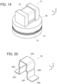
- FIG. 19 shows a partial perspective view of a connector 31 according to Embodiment 3.
- the connector 31 includes a top insulator 36 and a bottom insulator 37 separately disposed on opposite sides in the Z direction of the sheet type conductive member 15 with the sheet type conductive member 15 being sandwiched therebetween, and a plug contact 33 is retained by the top insulator 36.
- the plug contact 33 is formed of a bent plate-like member made of a conductive material such as metal and includes a top plate portion 33A of flat plate shape extending along an XY plane.
- Axially extending portions 33B and 33C extending in the -Z direction along a YZ plane are respectively joined to a -X directional end portion and a +X directional end portion of the top plate portion 33A, an orthogonally extending portion 33D extending in the -X direction along an XY plane is joined to a -Z directional end portion of the axially extending portion 33B, and an orthogonally extending portion 33E extending in the +X direction along an XY plane is joined to a -Z directional end portion of the axially extending portion 33C.
- the axially extending portions 33B and 33C face each other in the X direction, and a recessed portion 33F is formed between the axially extending portions 33B and 33C.
- This plug contact 33 may be retained by the top insulator 36 by, for example, press-fitting.
- the plug contact 33 retained by the top insulator 36 is disposed such that the recessed portion 33F opens in the -Z direction, and the inner contact 18 retained by the bottom insulator 37 is pushed in the +Z direction through the opening portion 15A of the sheet type conductive member 15 with the sheet type conductive member 15 being disposed between the top insulator 36 and the bottom insulator 37, whereby the crossing portion 18A, the first extending portion 18B, and the second extending portion 18D of the inner contact 18 are inserted into the recessed portion 33F of the plug contact 33.
- the inner contact 18 is the same as the inner contact 18 used in Embodiments 1 and 2 above.
- the first contacting portion P1 and the second contacting portion P2 of the inner contact 18 respectively make contact with the axially extending portions 33B and 33C of the plug contact 33, whereby the inner contact 18 is electrically connected to the plug contact 33, and the third contacting portion P3 is elastically displaced in the -Z direction and makes contact with the bottom surface of the sheet type conductive member 15 disposed on the -Z direction side of the orthogonally extending portion 33D of the plug contact 33.
- the wiring layer 15B exposed on the top surface of the sheet type conductive member 15 is electrically connected to the plug contact 33 directly, and the wiring layer 15D exposed on the bottom surface of the sheet type conductive member 15 is electrically connected to the plug contact 33 via the inner contact 18. That is, both the wiring layer 15B and the wiring layer 15D disposed on the top surface side and the bottom surface side of the sheet type conductive member 15 can be electrically connected to the single plug contact 33.
- first contacting portion P1 and the second contacting portion P2 of the inner contact 18 respectively make contact with the axially extending portions 33B and 33C of the plug contact 33
- third contacting portion P3 makes contact with the bottom surface of the sheet type conductive member 15, whereby the inner contact 18 is supported at three points by the plug contact 33 as with Embodiment 2 above.
- FIG. 22 shows a partial perspective view of a connector 41 according to Embodiment 4.
- the connector 41 includes a top insulator 46 and a bottom insulator 47 separately disposed on opposite sides in the Z direction of the sheet type conductive member 15 with the sheet type conductive member 15 being sandwiched therebetween, and a plug contact 43 is retained by the top insulator 46.
- the plug contact 43 is formed of a bent plate-like member made of a conductive material such as metal and includes an axially extending portion 43A extending along a YZ plane, and an orthogonally extending portion 43B bent at a - Z directional end portion of the axially extending portion 43A and extending in the -Z direction along an XY plane.
- This plug contact 43 may be retained by the top insulator 46 by, for example, press-fitting.
- the top insulator 46 which retains the plug contact 43 has a dent facing a +X directional surface of the axially extending portion 43A of the plug contact 43, and the dent of the top insulator 46 and the axially extending portion 43A of the plug contact 43 form a recessed portion R opening in the -Z direction.
- the inner contact 18 retained by the bottom insulator 47 is pushed in the +Z direction through the opening portion 15A of the sheet type conductive member 15 with the sheet type conductive member 15 being disposed between the top insulator 46 and the bottom insulator 47, whereby the crossing portion 18A, the first extending portion 18B, and the second extending portion 18D of the inner contact 18 are inserted into the recessed portion R.
- the first contacting portion P1 of the inner contact 18 makes contact with the +X directional surface of the axially extending portion 43A of the plug contact 43, whereby the inner contact 18 is electrically connected to the plug contact 43, and the third contacting portion P3 is elastically displaced in the -Z direction and makes contact with the bottom surface of the sheet type conductive member 15 disposed on the -Z direction side of the orthogonally extending portion 43B of the plug contact 43.
- the wiring layer 15B exposed on the top surface of the sheet type conductive member 15 is electrically connected to the plug contact 43 directly, and the wiring layer 15D exposed on the bottom surface of the sheet type conductive member 15 is electrically connected to the plug contact 43 via the inner contact 18. That is, both the wiring layer 15B and the wiring layer 15D disposed on the top surface side and the bottom surface side of the sheet type conductive member 15 can be electrically connected to a single plug contact 43.
- first contacting portion P1 of the inner contact 18 makes contact with the axially extending portion 43A of the plug contact 43
- the second contacting portion P2 makes contact with the surface of the dent of the top insulator 46 which dent forms part of the recessed portion R
- the third contacting portion P3 makes contact with the bottom surface of the sheet type conductive member 15, whereby the inner contact 18 is supported with respect to the plug contact 43.
- the plug contact 33, 34 in Embodiments 3 and 4 above does not have any receiving portion formed of a dent, as with the plug contact 13 in Embodiment 1, the axially extending portion 33B of the plug contact 33 or the axially extending portion 43A of the plug contact 43 may be provided with a receiving portion formed of a dent so that the receiving portion receives the hook portion 18E of the inner contact 18.
- plug contact 13, 23, 33, 43 is connected to both the wiring layer 15B and the wiring layer 15D respectively exposed on the top surface side and the bottom surface side of the sheet type conductive member 15 in Embodiments 1 to 4 above, only the wiring layer 15D exposed on the bottom surface side of the sheet type conductive member 15 may be connected to the plug contact 13, 23, 33, 43, for instance.
- the sheet type conductive member 15 used in Embodiments 1 to 4 above has a multilayer structure, the invention is not limited thereto, and it suffices if the sheet type conductive member has a conductor exposed on at least one surface thereof.
- the two layers of the conductors i.e., the wiring layer 15B and the wiring layer 15D of a sheet type conductive member 15, are connected to a single plug contact 13, 23, 33, 43 in Embodiments 1 to 4 above, the invention is not limited thereto, and three or more layers of conductors may be connected to a single plug contact 13, 23, 33, 43.
- the connector 11 according to Embodiment 1 above has the four plug contacts 13, the invention is not limited to this number of the plug contacts 13, and it suffices if the connector includes at least a single plug contact 13 to be electrically connected to a conductor exposed on at least one surface of the sheet type conductive member 15.
- the connector 21, 31, 41 according to Embodiments 2 to 4 above may have four plug contacts 23, 33, 43.
Landscapes
- Coupling Device And Connection With Printed Circuit (AREA)
Abstract
Description
- The present invention relates to a connector, particularly to a connector connected to a sheet type connection object having a conductor exposed on at least one surface of the connection object.
- In recent years, attention has been drawn to so-called smart clothes that can obtain user's biological data such as the heart rate and the body temperature only by being worn by the user. Such smart clothes have an electrode disposed at a measurement site, and when a wearable device serving as a measurement device is electrically connected to the electrode, biological data can be transmitted to the wearable device.
- The electrode and the wearable device can be interconnected by, for instance, use of a connector connected to a conductor drawn from the electrode.
- As a connector of this type, for example,
JP 2018-129244 A FIG. 25 . This connector includes ahousing 2 and abase member 3 that are separately disposed on opposite sides of aflexible substrate 1 to sandwich theflexible substrate 1.Tubular portions 4A ofcontacts 4 are passed through contact through-holes 2A of thehousing 2, andflanges 4B of thecontacts 4 are sandwiched between thehousing 2 andconductors 1A exposed on the top surface of theflexible substrate 1. - In this state, by pushing the
base member 3 toward thehousing 2, as shown inFIG. 26 , aprojection 3A of thebase member 3 is inserted into aprojection accommodating portion 4C of thecontact 4 with theflexible substrate 1 being sandwiched therebetween, and an inner surface of theprojection accommodating portion 4C makes contact with theconductor 1A with a predetermined contact force, whereby thecontact 4 is electrically connected to theconductor 1A. - Further,
housing fixing posts 3B formed to project from thebase member 3 are press-fitted into post accommodatingportions 2B of thehousing 2 as shown inFIG. 25 , so that thehousing 2 and thebase member 3 are fixed to each other. - When a wearable device is fitted with the connector disclosed in
JP 2018-129244 A - However, when the
conductor 1A is exposed on the bottom surface of theflexible substrate 1, the connector ofJP 2018-129244A conductor 1A to thecontact 4, disadvantageously. - The present invention has been made to solve the foregoing problem and aims at providing a connector that enables to make an electrical connection of a contact to a conductor of a connection object regardless of whether the conductor is exposed on the top surface or the bottom surface of the connection object.
- A connector according to the present invention comprises:
- a plug contact having conductivity and including an axially extending portion that forms at least part of an inner surface of a recessed portion extending along a fitting axis, and an orthogonally extending portion joined to the axially extending portion and extending from a base end of the recessed portion in a direction orthogonal to the fitting axis; and
- an inner contact having conductivity that is elastically deformable and is supported in a state of being partially inserted in the recessed portion,
- wherein the inner contact includes: a first contacting portion that makes contact with the inner surface of the recessed portion formed by the axially extending portion and is electrically connected to the plug contact; a second contacting portion that makes contact with the inner surface of the recessed portion on an opposite side from the first contacting portion across the fitting axis at a position closer to the base end of the recessed portion than the first contacting portion; and a third contacting portion extending in a direction orthogonal to the fitting axis and facing the orthogonally extending portion, and
- wherein part of a connection object of sheet shape having a conductor exposed on at least one surface of the connection object is sandwiched between a bottom surface of the orthogonally extending portion of the plug contact and the third contacting portion of the inner contact in a direction along the fitting axis, the bottom surface of the orthogonally extending portion makes contact with a top surface of the connection object, and the third contacting portion makes contact with a bottom surface of the connection object, whereby the plug contact is electrically connected to the conductor directly when the conductor is exposed on the top surface of the connection object, and the plug contact is electrically connected to the conductor via the inner contact when the conductor is exposed on the bottom surface of the connection object.
-
-
FIG. 1 is a perspective view showing a connector according toEmbodiment 1 connected to a connection object. -
FIG. 2 is an exploded perspective view of the connector according toEmbodiment 1. -
FIG. 3 is a perspective view showing a top insulator used in the connector ofEmbodiment 1. -
FIG. 4 is a perspective view showing a bottom insulator used in the connector ofEmbodiment 1. -
FIG. 5 is a perspective view showing a projection formed at the bottom insulator. -
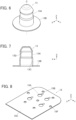
FIG. 6 is a perspective view showing a plug contact used in the connector ofEmbodiment 1. -
FIG. 7 is a cross-sectional view showing the plug contact used in the connector ofEmbodiment 1. -
FIG. 8 is a perspective view of the connection object to be connected to the connector ofEmbodiment 1, as viewed from an obliquely upper position. -
FIG. 9 is a perspective view of the connection object to be connected to the connector ofEmbodiment 1, as viewed from an obliquely lower position. -
FIG. 10 is a perspective view showing an inner contact used in the connector ofEmbodiment 1. -
FIG. 11 is a perspective view of the inner contact used in the connector ofEmbodiment 1, as viewed from an angle different fromFIG. 10 -
FIG. 12 is a side view showing the inner contact used in the connector ofEmbodiment 1. -
FIG. 13 is a perspective view of the connector in the process of assembling, as viewed from an obliquely lower position. -
FIG. 14 is a partial cross-sectional side view showing the connector ofEmbodiment 1 connected to the connection object. -
FIG. 15 is an enlarged view of an important part ofFIG. 14 . -
FIG. 16 is a perspective view showing a plug contact used in a connector ofEmbodiment 2. -
FIG. 17 is a cross-sectional view showing the plug contact used in the connector ofEmbodiment 2. -
FIG. 18 is a partial cross-sectional side view showing the connector ofEmbodiment 2 connected to the connection object. -
FIG. 19 is a partial perspective view showing a connector according toEmbodiment 3 connected to the connection object. -
FIG. 20 is a perspective view showing a plug contact used in the connector ofEmbodiment 3. -
FIG. 21 is a partial cross-sectional side view showing the connector ofEmbodiment 3 connected to the connection object. -
FIG. 22 is a partial perspective view showing a connector according toEmbodiment 4 connected to the connection object. -
FIG. 23 is a perspective view showing a plug contact used in the connector ofEmbodiment 4. -
FIG. 24 is a partial cross-sectional side view showing the connector ofEmbodiment 4 connected to the connection object. -
FIG. 25 is an exploded perspective view of a conventional connector. -
FIG. 26 is a partial cross-sectional view showing the conventional connector. - An embodiment of the present invention is described below based on the accompanying drawings.
-
FIG. 1 shows aconnector 11 according toEmbodiment 1. Theconnector 11 is, for instance, used as a garment-side connector for fitting a wearable device and has ahousing 12 made of an insulating material. Fourplug contacts 13 are retained in thehousing 12, and a sheet typeconductive member 15 is retained by thehousing 12. The sheet typeconductive member 15 constitutes a sheet type connection object to which theconnector 11 is connected. - The four
plug contacts 13 are arranged in two rows parallel to each other and disposed to project perpendicularly to the sheet typeconductive member 15. - For convenience, the sheet type
conductive member 15 is defined as extending in an XY plane, the arrangement direction of the fourplug contacts 13 is referred to as "Y direction," and the direction in which the fourplug contacts 13 project is referred to as "+Z direction." The Z direction is a fitting direction in which theconnector 11 is fitted to a counter connector. -
FIG. 2 shows an exploded perspective view of theconnector 11. Theconnector 11 includes atop insulator 16 and abottom insulator 17, and these top andbottom insulators housing 12. - The four
plug contacts 13 are disposed on the -Z direction side of thetop insulator 16, and the sheet typeconductive member 15 is disposed on the -Z direction side of the fourplug contacts 13. Further, fourinner contacts 18 are disposed on the -Z direction side of the sheet typeconductive member 15, and thebottom insulator 17 is disposed on the -Z direction side of the fourinner contacts 18. The fourinner contacts 18 separately correspond to the fourplug contacts 13. - As shown in
FIG. 3 , thetop insulator 16 includes a recessedportion 16A opening in the +Z direction, and four contact through-holes 16B formed within the recessedportion 16A. The recessedportion 16A constitutes a counter connector accommodating portion in which part of a counter connector (not shown) is to be accommodated, and the four contact through-holes 16B separately correspond to the fourplug contacts 13. In addition, on a surface, facing in the -Z direction, of thetop insulator 16, a plurality ofbosses 16C are formed to project in the -Z direction. - As shown in
FIG. 4 , thebottom insulator 17 includes aflat plate portion 17A, and fourcontact arrangement regions 17B are defined on a top surface, facing in the +Z direction, of theflat plate portion 17A. Thecontact arrangement region 17B is a circular region for arranging thecorresponding plug contact 13 via the sheet typeconductive member 15. The fourcontact arrangement regions 17B are separately provided with fourprojections 17C projecting in the +Z direction from center parts of thecontact arrangement regions 17B. - In addition, the
flat plate portion 17A is provided with a plurality of through-holes 17D separately corresponding to the plurality ofbosses 16C of thetop insulator 16. - As shown in
FIG. 5 , theprojection 17C formed in thecontact arrangement region 17B of thebottom insulator 17 has a substantially columnar shape extending in the Z direction along a fitting axis C of theplug contact 13 disposed to correspond to thecontact arrangement region 17B, and anaccommodating groove 17E for accommodating the correspondinginner contact 18 is formed at X-directional opposite lateral surfaces and a +Z directional end portion of theprojection 17C. Theaccommodating groove 17E continuously extends in a top surface of thecontact arrangement region 17B on the -X direction side of theprojection 17C. - The four
plug contacts 13 are each made of a conductive material such as metal, and are to be connected to corresponding contacts of a counter connector (not shown) when part of the counter connector is accommodated in the recessedportion 16A of thetop insulator 16. - As shown in
FIG. 6 , theplug contact 13 has atubular portion 13A of cylindrical shape extending in the Z direction along the fitting axis C, and aflange 13B of flat plate shape extending from a -Z directional end portion of thetubular portion 13A along an XY plane. Thetubular portion 13A constitutes an axially extending portion, while theflange 13B constitutes an orthogonally extending portion. - As shown in
FIG. 7 , thetubular portion 13A is provided in its interior with a recessedportion 13C opening in the -Z direction, and the recessedportion 13C is provided in its inside with a receivingportion 13D formed of a dent annularly extending in an XY plane along an inner surface of the recessedportion 13C. - The fitting axis C is an axis passing the center of the
tubular portion 13A and extending in the Z direction that is the fitting direction between theconnector 11 and a counter connector. - While the
tubular portion 13A has a cylindrical shape, the cross-sectional shape thereof is not limited to a circular shape, and thetubular portion 13A may have various cross-sectional shapes such as an elliptical shape and a polygonal shape as long as thetubular portion 13A is provided in its interior with the recessedportion 13C. - All the four
plug contacts 13 may be each used as a terminal for transmitting an electric signal. - The sheet type
conductive member 15 has a multilayer structure in which a plurality of wiring layers each formed from a conductor and a plurality of insulating layers are laminated. - As shown in
FIG. 8 , the sheet typeconductive member 15 is provided with fourcircular opening portions 15A penetrating the sheet typeconductive member 15 in the Z direction. The fouropening portions 15A separately correspond to the fourplug contacts 13. On a top surface, facing in the +Z direction, of the sheet typeconductive member 15, awiring layer 15B is exposed toward the +Z direction so as to be adjacent to the openingportions 15A on the -X direction side of the openingportions 15A, while an insulatinglayer 15C is exposed in a region other than the regions corresponding to the four openingportions 15A and the four parts of thewiring layer 15B adjacent to these openingportions 15A. - Since the opening
portions 15A penetrate the sheet typeconductive member 15 in the Z direction, as shown inFIG. 9 , the four openingportions 15A can be seen also on a bottom surface, facing in the -Z direction, of the sheet typeconductive member 15. - On the bottom surface, facing in the -Z direction, of the sheet type
conductive member 15, awiring layer 15D is exposed toward the -Z direction so as to be adjacent to the four openingportions 15A on the X direction side of the openingportions 15A, while an insulatinglayer 15E is exposed in a region other than the regions corresponding to the four openingportions 15A and the four parts of thewiring layer 15D adjacent to these openingportions 15A. - In addition, as shown in
FIGS. 8 and9 , a plurality of through-holes 15F separately corresponding to the plurality ofbosses 16C of thetop insulator 16 are formed at a peripheral portion of the sheet typeconductive member 15. - As shown in
FIGS. 10 and 11 , theinner contact 18 is formed of a single band type metal sheet having conductivity and being bent, and has a crossingportion 18A extending in the X direction. A first extendingportion 18B extends in the -Z direction from a -X directional end portion of the crossingportion 18A, anarm portion 18C extends in the -X direction from a -Z directional end portion of the first extendingportion 18B, and a second extendingportion 18D extends in the -Z direction from a +X directional end portion of the crossingportion 18A. The crossingportion 18A, the first extendingportion 18B, and the second extendingportion 18D are inserted into the recessedportion 13C of thecorresponding plug contact 13 when theconnector 11 is assembled. - A
hook portion 18E projecting in the -X direction is formed at a joint portion between the crossingportion 18A and the first extendingportion 18B. Thehook portion 18E projects in a right angle shape or a chevron shape toward the -X direction, and a first contacting portion P1 facing in the -Z direction is set at a -X directional end portion of thehook portion 18E. - In addition, a
curved portion 18F that is curved to protrude in the +X direction is formed at a -Z directional end portion of the second extendingportion 18D, and a second contacting portion P2 facing in the +X direction is set on a +X directional surface of thecurved portion 18F. - Further, a
curved portion 18G that is curved to protrude toward the +Z direction is formed at a -X directional end portion of thearm portion 18C, and a third contacting portion P3 facing in the +Z direction is set on a +Z directional surface of thecurved portion 18G. - While the position of the
inner contact 18 is slightly inclined with respect to the fitting axis C when the crossingportion 18A, the first extendingportion 18B, and the second extendingportion 18D are inserted in the recessedportion 13C of theplug contact 13 such that the crossingportion 18A crosses the fitting axis C as shown inFIG. 12 , in a natural state where no external force is applied to theinner contact 18, a distance L11 in the X direction from the first contacting portion P1 to the second contacting portion P2 is set to be larger than a distance L21 in the X direction from the receivingportion 13D of theplug contact 13 to a part of an inner surface of the recessedportion 13C which part faces the receivingportion 13D. - Similarly, in the natural state where no external force is applied to the
inner contact 18, a distance L12 in the Z direction from the first contacting portion P1 to the third contacting portion P3 is set to be smaller than a distance L22 in the Z direction from the receivingportion 13D of theplug contact 13 to the bottom surface of the sheet typeconductive member 15 disposed on the -Z direction side of theflange 13B. - Therefore, when the crossing
portion 18A, the first extendingportion 18B, and the second extendingportion 18D are inserted into the recessedportion 13C of theplug contact 13, theinner contact 18 elastically deforms as shown by a dashed line inFIG. 12 , the second contacting portion P2 makes contact with the inner surface of the recessedportion 13C of theplug contact 13, and the third contacting portion P3 makes contact with the bottom surface of the sheet typeconductive member 15. - The
inner contact 18 configured as above can be easily produced by, for example, cutting out a metal sheet into a predetermined shape and then bending the cut metal sheet. - The four contact through-
holes 16B of thetop insulator 16, the fourplug contacts 13, the four openingportions 15A of the sheet typeconductive member 15, the fourinner contacts 18, and the fourcontact arrangement regions 17B of thebottom insulator 17 are arranged so as to align with each other in the Z direction. - In addition, the
bosses 16C of thetop insulator 16, the through-holes 15F of the sheet typeconductive member 15, and the through-holes 17D of thebottom insulator 17 are arranged so as to align with each other in the Z direction. - When the
connector 11 is assembled, first, the fourinner contacts 18 are separately accommodated in theaccommodating grooves 17E of the fourprojections 17C of thebottom insulator 17. - Subsequently, the
tubular portions 13A of theplug contacts 13 are inserted into the four contact through-holes 16B of thetop insulator 16 correspondingly from the -Z direction, and thebottom insulator 17 is pressed toward thetop insulator 16 in the +Z direction with the sheet typeconductive member 15 being sandwiched therebetween. - At this time, the
inner contact 18 accommodated in theaccommodating groove 17E of theprojection 17C of thebottom insulator 17 is pushed up in the +Z direction, and the crossingportion 18A, the first extendingportion 18B, and the second extendingportion 18D of theinner contact 18 are inserted into the recessedportion 13C of thecorresponding plug contact 13 through theopening portion 15B of the sheet typeconductive member 15. In addition, theflange 13B of theplug contact 13 is situated around thecorresponding opening portion 15B of the sheet typeconductive member 15, and the sheet typeconductive member 15 is sandwiched between the +Z directional surface of thecurved portion 18G formed at the -X directional end portion of thearm portion 18C of theinner contact 18 and a bottom surface on the -Z direction side of theflange 13B of theplug contact 13. - In addition, by pressing the
bottom insulator 17 against thetop insulator 16, thebosses 16C of thetop insulator 16 sequentially penetrate the through-holes 15F of the sheet typeconductive member 15, and the through-holes 17D of thebottom insulator 17. Thereafter, as shown inFIG. 13 , thetop insulator 16 and thebottom insulator 17 are fixed to each other through heat deformation of a tip of each of the plurality ofbosses 16C projecting on the -Z direction side of thebottom insulator 17. Thus, the assembling operation of theconnector 11 is completed. - As shown in
FIG. 14 , when theinner contact 18 is pushed up in the +Z direction by theprojection 17C of thebottom insulator 17, theinner contact 18 elastically deforms, the crossingportion 18A, the first extendingportion 18B, and the second extendingportion 18D move in the +Z direction within the recessedportion 13C of theplug contact 13, and thehook portion 18E is received by the receivingportion 13D formed inside the recessedportion 13C of theplug contact 13. - Here, as shown in
FIG. 12 , in the natural state where no external force is applied to theinner contact 18, the distance L11 in the X direction from the first contacting portion P1 to the second contacting portion P2 is set to be larger than the distance L21 in the X direction from the receivingportion 13D of theplug contact 13 to a part of the inner surface of the recessedportion 13C which part faces the receivingportion 13D. - Therefore, as shown in
FIG. 14 , when the crossingportion 18A, the first extendingportion 18B, and the second extendingportion 18D are inserted into the recessedportion 13C of theplug contact 13, the first contacting portion P1 and the second contacting portion P2 are elastically displaced such that the gap therebetween in the X direction is narrowed, and are pressed against the inner surface of the recessedportion 13C of theplug contact 13. - Specifically, the first contacting portion P1 is pressed against the receiving
portion 13D within the recessedportion 13C of theplug contact 13, while the second contacting portion P2 is pressed against the inner surface of the recessedportion 13C of theplug contact 13 on the opposite side from the first contacting portion P1 across the fitting axis C. These first and second contacting portions P1 and P2 are pressed against and makes contact with the inner surface of the recessedportion 13C of theplug contact 13, whereby theinner contact 18 is electrically connected to theplug contact 13. - In addition, as shown in
FIG. 12 , in the natural state where no external force is applied to theinner contact 18, the distance L12 in the Z direction from the first contacting portion P1 to the third contacting portion P3 is set to be smaller than the distance L22 in the Z direction from the receivingportion 13D of theplug contact 13 to the bottom surface of the sheet typeconductive member 15 disposed on the -Z direction side of theflange 13B. - Therefore, as shown in
FIG. 14 , when the crossingportion 18A, the first extendingportion 18B, and the second extendingportion 18D are inserted into the recessedportion 13C of theplug contact 13 such that the crossingportion 18A crosses the fitting axis C, the third contacting portion P3 is elastically displaced in the -Z direction and makes contact with the bottom surface of the sheet typeconductive member 15 disposed on the -Z direction side of theflange 13B of theplug contact 13. Therefore, the top surface on the +Z direction side of the sheet typeconductive member 15 is pressed against the bottom surface of theflange 13B of theplug contact 13, while the bottom surface on the -Z direction side of the sheet typeconductive member 15 is pressed against the third contacting portion P3 of theinner contact 18. - Here, as shown in
FIGS. 8 and9 , on the top surface of the sheet typeconductive member 15, thewiring layer 15B is exposed so as to be adjacent to the openingportions 15A on the -X direction side of the openingportions 15A, and on the bottom surface of the sheet typeconductive member 15, thewiring layer 15D is exposed so as to be adjacent to the openingportions 15A on the -X direction side of the openingportions 15A. - Therefore, the
wiring layer 15B on the top surface of the sheet typeconductive member 15 makes contact with the bottom surface of theflange 13B of theplug contact 13 with predetermined contact pressure, while thewiring layer 15D on the bottom surface of the sheet typeconductive member 15 makes contact with the third contacting portion P3 of theinner contact 18 with predetermined contact pressure. - Therefore, the
wiring layer 15B exposed on the top surface of the sheet typeconductive member 15 is electrically connected to theplug contact 13 directly, and thewiring layer 15D exposed on the bottom surface of the sheet typeconductive member 15 is electrically connected to theplug contact 13 via theinner contact 18. In other words, both the wiring layers 15B and 15D are connected to theplug contact 13. - Thus, with the
connector 11, both thewiring layer 15B and thewiring layer 15D formed of the conductors disposed on the top surface side and the bottom surface side of the sheet typeconductive member 15 can be electrically connected to asingle plug contact 13 by use of theinner contact 18. - Therefore, when the
connector 11 is connected to a sheet type conductive member having a conductor exposed only on its top surface side, theplug contact 13 can be electrically connected to the conductor on the top surface side of the sheet type conductive member. On the other hand, when theconnector 11 is connected to a sheet type conductive member having a conductor exposed only on its bottom surface side, theplug contact 13 can be electrically connected to the conductor on the bottom surface side of the sheet type conductive member. - Further, when the
connector 11 is connected to a sheet type conductive member having conductors separately exposed on its top surface side and bottom surface side like the sheet typeconductive member 15 inEmbodiment 1 above, theplug contact 13 can be electrically connected to both the conductors on the top surface side and the bottom surface side of the sheet type conductive member. For example, assuming that a connection object is a sheet type conductive member having a multilayer structure in which conductors constituting shield layers are separately exposed on the top surface side and the bottom surface side and a conductor constituting a signal wiring layer is disposed between these shield layers so as to be insulated from both the shield layers, a shield effect with respect to the signal wiring layer is exhibited when theplug contact 13 connected to the shield layers on the top surface side and the bottom surface side is connected to a ground potential, and it is possible to carry out highly accurate signal transmission with reduced influence of external disturbances caused by, for example, electromagnetic waves. - Note that the
flange 13B of each of theplug contacts 13 is sandwiched between thetop insulator 16 and thebottom insulator 17, so that theplug contacts 13 are fixed to thetop insulator 16 and thebottom insulator 17. - The first contacting portion P1 and the second contacting portion P2 of the
inner contact 18 are elastically displaced such that the gap therebetween in the X direction is narrowed, and make contact with the inner surface of the recessedportion 13C of theplug contact 13, and the third contacting portion P3 is elastically displaced in the -Z direction and makes contact with the bottom surface of the sheet typeconductive member 15; therefore, as shown inFIG. 14 , theinner contact 18 is retained by theplug contact 13 in the state where: the first contacting portion P1 receives a force F1 acting in the +X direction and the +Z direction from the receivingportion 13D of the recessedportion 13C of theplug contact 13; the second contacting portion P2 receives a force F2 acting in the -X direction from the inner surface of the recessedportion 13C of theplug contact 13; and the third contacting portion P3 receives a force F3 acting in the -Z direction from the bottom surface of the sheet typeconductive member 15. - That is, if a frictional force is ignored, these three
forces F 1, F2 and F3 balance, and when an X directional component force and a Z directional component force of the force F1 are F 1X and F 1Z, respectively, the following relations are established:

- Note that F1, F2, F3, F1X, and F1Z are all represented by absolute values.
- In addition, from balance of moments about the first contacting portion P1, when a distance in the X direction between the first contacting portion P1 and the third contacting portion P3 is LX, and a distance in the Z direction between the first contacting portion P1 and the second contacting portion P2 is LZ, the following relation is established:

- From the formulae (1), (2), and (3) above, the following formula can be obtained:

- As shown in
FIG. 15 , a tangential plane formed by thehook portion 18E and the receivingportion 13D contacting each other in the case where the receivingportion 13D of theplug contact 13 receives thehook portion 18E of theinner contact 18 is assumed to be T, and a normal line perpendicular to the tangential plane T is assumed to be N. If a frictional force exerted between theinner contact 18 and theplug contact 13 is ignored, theforce F 1 along the normal line N is applied from the receivingportion 13D of theplug contact 13 to the first contacting portion P1 set at the -X directional end portion of thehook portion 18E. - That is, a ratio of the Z directional component force F 1Z to the X directional component force F1X of the force F1 (F1Z/F1X) is equal to an inclination S of the normal line N.
- Thus, the
inner contact 18 is supported at three points by theplug contact 13 by means of the first contacting portion P1, the second contacting portion P2, and the third contacting portion P3 in the state where the forces F1, F2, and F3 applied to theinner contact 18 balance and the moments balance. - Here, the case is assumed where, for example, an inner contact that is the same as the
inner contact 18 except that a X directional length of thearm portion 18C is larger than that of theinner contact 18 is used instead of theinner contact 18. It is assumed that elastic displacement of the first contacting portion P1 and the second contacting portion P2 is similar to that in the case of theinner contact 18 and that the magnitude of the force F2 applied from the inner surface of the recessedportion 13C of theplug contact 13 to the second contacting portion P2 does not change. - Since the distance LX in the X direction between the first contacting portion P1 and the third contacting portion P3 becomes large according to the length of the
arm portion 18C, in order to balance the moments about the first contacting portion P1, from the formula (3) above, the force F3 acting in the -Z direction to be applied to the third contacting portion P3 becomes small, and accordingly, the Z directional component force F1Z of the force F1 is also reduced. On the other hand, since the X directional component force F1X of the force F1 does not change as with the force F2, the ratio (F1Z/F1X) becomes smaller than the inclination S of the normal line N. - However, if the frictional force is ignored, the force F1 along the normal line N is applied, as a perpendicular reaction force from the tangential plane T, to the first contacting portion P1, and a force acting in the +Z direction, which corresponds to the reduction of the Z directional component force F1Z of the force F1, is applied to the first contacting portion P1. As a result, the
inner contact 18 is prevented from falling off theplug contact 13 in the -Z direction. - Next, the case is assumed where an inner contact that is the same as the
inner contact 18 except that the X directional length of thearm portion 18C is smaller than that of theinner contact 18 is used instead of theinner contact 18. It is assumed that elastic displacement of the first contacting portion P1 and the second contacting portion P2 is similar to that in the case of theinner contact 18 and that the magnitude of the force F2 applied from the inner surface of the recessedportion 13C of theplug contact 13 to the second contacting portion P2 does not change. - Since the distance LX in the X direction between the first contacting portion P1 and the third contacting portion P3 becomes small according to the reduction in the length of the
arm portion 18C, in order to balance the moments about the first contacting portion P1, from the formula (3) above, the force F3 acting in the -Z direction to be applied to the third contacting portion P3 becomes large, and accordingly, the Z directional component force F1Z of the force F1 also increases. On the other hand, since the X directional component force F1X of the force F1 does not change as with the force F2, the ratio (F1Z/F1X) becomes larger than the inclination S of the normal line N. - However, if the frictional force is ignored, the force F1 along the normal line N is applied, as a perpendicular reaction force from the tangential plane T, to the first contacting portion P1, and a force acting in the -Z direction, which corresponds to the increase in the Z directional component force F1Z of the force F1 is applied to the first contacting portion P1. As a result, the
inner contact 18 easily falls off theplug contact 13 in the -Z direction. - That is, in order for the
inner contact 18 to be stably supported at three points by theplug contact 13, the ratio LZ/LX of the distance LZ in the Z direction between the first contacting portion P1 and the second contacting portion P2 to the distance LX in the X direction between the first contacting portion P1 and the third contacting portion P3 is preferably not more than the inclination S with respect to the X direction of the normal line N perpendicular to the tangential plane T formed by thehook portion 18E and the receivingportion 13D contacting each other in the case where the receivingportion 13D receives thehook portion 18E. - Even when a frictional force that cannot be ignored is exerted between the
inner contact 18 and theplug contact 13, theinner contact 18 can be stably supported by theplug contact 13 by setting the ratio LZ/LX to be not more than the inclination S of the normal line N. - While the receiving
portion 13D formed inside the recessedportion 13C of theplug contact 13 receives thehook portion 18E of theinner contact 18 inEmbodiment 1 above, the invention is not limited thereto, and a plug contact having no receivingportion 13D may be used by utilizing a static frictional force. -
FIG. 16 shows aplug contact 23 used in aconnector 21 according toEmbodiment 2. As with theplug contact 13 inEmbodiment 1, theplug contact 23 is made of a conductive material such as metal and has atubular portion 23A of cylindrical shape and extending in the Z direction along the fitting axis C, and aflange 23B extending from a -Z directional end portion of thetubular portion 23A along an XY plane. - As shown in
FIG. 17 , thetubular portion 23A is provided in its interior with a recessedportion 23C opening in the -Z direction, but the receiving portion formed of the dent included in theplug contact 13 inEmbodiment 1 is not formed inside the recessedportion 23C. -
FIG. 18 shows theconnector 21 ofEmbodiment 2 connected to the sheet typeconductive member 15. Theconnector 21 is configured to use theplug contact 23 in place of theplug contact 13 in theconnector 11 ofEmbodiment 1 shown inFIG. 14 , and the other members are the same as those of theconnector 11 ofEmbodiment 1. - When the crossing
portion 18A, the first extendingportion 18B, and the second extendingportion 18D of theinner contact 18 are inserted into the recessedportion 23C of theplug contact 23, the first contacting portion P1 and the second contacting portion P2 are elastically displaced such that the gap therebetween in the X direction is narrowed. Thus, a force F1 acting in the +X direction from an inner surface of the recessedportion 23C of theplug contact 23 is applied to the first contacting portion P1, and a force F2 acting in the -X direction from the inner surface of the recessedportion 23C of theplug contact 23 is applied to the second contacting portion P2. - In addition, the third contacting portion P3 set at the tip of the
arm portion 18C makes contact with the bottom surface of the sheet typeconductive member 15 disposed on the -Z direction side of theflange 23B of theplug contact 23 and is elastically displaced in the -Z direction, and a force F3 acting in the -Z direction from the bottom surface of the sheet typeconductive member 15 is applied to the third contacting portion P3. - This force F3 is directed to -Z direction, so that falling off of the
inner contact 18 from theplug contact 23 is promoted; however, since the first contacting portion P1 and the second contacting portion P2 make contact with the inner surface of the recessedportion 23C of theplug contact 23 and receive the forces F1 and F2 in the X direction, static frictional forces F1A and F2A acting in the +Z direction are exerted on the first contacting portion P1 and the second contacting portion P2, respectively. - The forces F1, F2, and F3 and the static frictional forces F1A and F2A balance, and in this state, the
inner contact 18 is supported at three points by theplug contact 23. - At this time, from balance of the forces, the following relations are established:


- Note that
F 1, F2, F3, F1A, and F2A are all represented by absolute values. - From balance of the moments about the first contacting
portion P 1, when a distance in the X direction between the first contacting portion P1 and the second contacting portion P2 is LX2, a distance in the X direction between the first contacting portion P1 and the third contacting portion P3 is LX3, and a distance in the Z direction between the first contacting portion P1 and the second contacting portion P2 is LZ2, the following relation is established:
- Further, when a static frictional coefficient between the inner surface of the recessed
portion 23C of theplug contact 23 and each of the first contacting portion P1 and the second contacting portion P2 of theinner contact 18 is M, the following relations are established:

- When the static frictional coefficient M is calculated from the formulae (5) to (9) above,

- Therefore, when the ratio represented by the distances LX2, LX3, and LZ2 among the first contacting portion P1, the second contacting portion P2, and the third contacting portion P3 [LZ2 / (LX2 + 2 x LX3)] is not more than the static frictional coefficient M between the inner surface of the recessed
portion 23C of theplug contact 23 and each of the first contacting portion P1 and the second contacting portion P2 of theinner contact 18, the formulae (5) to (9) above are established, and theinner contact 18 is retained by theplug contact 23. - Thus, even when the
plug contact 23 having no receiving portion is used, theinner contact 18 can be stably supported at three points by theplug contact 23 without falling off theplug contact 23 in the -Z direction. - In addition, as with the
connector 11 ofEmbodiment 1, also in theconnector 21 ofEmbodiment 2, the first contacting portion P1 and the second contacting portion P2 make contact with the inner surface of the recessedportion 23C of theplug contact 23, and the third contacting portion P3 makes contact with the bottom surface of the sheet typeconductive member 15, so that both thewiring layer 15B and thewiring layer 15D respectively disposed on the top surface side and the bottom surface side of the sheet typeconductive member 15 can be electrically connected to asingle plug contact 23. - While the
plug contact tubular portion Embodiments -
FIG. 19 shows a partial perspective view of aconnector 31 according toEmbodiment 3. Theconnector 31 includes atop insulator 36 and abottom insulator 37 separately disposed on opposite sides in the Z direction of the sheet typeconductive member 15 with the sheet typeconductive member 15 being sandwiched therebetween, and aplug contact 33 is retained by thetop insulator 36. - As shown in
FIG. 20 , theplug contact 33 is formed of a bent plate-like member made of a conductive material such as metal and includes atop plate portion 33A of flat plate shape extending along an XY plane.Axially extending portions top plate portion 33A, anorthogonally extending portion 33D extending in the -X direction along an XY plane is joined to a -Z directional end portion of theaxially extending portion 33B, and anorthogonally extending portion 33E extending in the +X direction along an XY plane is joined to a -Z directional end portion of theaxially extending portion 33C. - The
axially extending portions portion 33F is formed between the axially extendingportions - This
plug contact 33 may be retained by thetop insulator 36 by, for example, press-fitting. - As shown in
FIG. 21 , theplug contact 33 retained by thetop insulator 36 is disposed such that the recessedportion 33F opens in the -Z direction, and theinner contact 18 retained by thebottom insulator 37 is pushed in the +Z direction through theopening portion 15A of the sheet typeconductive member 15 with the sheet typeconductive member 15 being disposed between thetop insulator 36 and thebottom insulator 37, whereby the crossingportion 18A, the first extendingportion 18B, and the second extendingportion 18D of theinner contact 18 are inserted into the recessedportion 33F of theplug contact 33. - Note that the
inner contact 18 is the same as theinner contact 18 used inEmbodiments - The first contacting portion P1 and the second contacting portion P2 of the
inner contact 18 respectively make contact with theaxially extending portions plug contact 33, whereby theinner contact 18 is electrically connected to theplug contact 33, and the third contacting portion P3 is elastically displaced in the -Z direction and makes contact with the bottom surface of the sheet typeconductive member 15 disposed on the -Z direction side of theorthogonally extending portion 33D of theplug contact 33. - Consequently, the
wiring layer 15B exposed on the top surface of the sheet typeconductive member 15 is electrically connected to theplug contact 33 directly, and thewiring layer 15D exposed on the bottom surface of the sheet typeconductive member 15 is electrically connected to theplug contact 33 via theinner contact 18. That is, both thewiring layer 15B and thewiring layer 15D disposed on the top surface side and the bottom surface side of the sheet typeconductive member 15 can be electrically connected to thesingle plug contact 33. - In addition, the first contacting portion P1 and the second contacting portion P2 of the
inner contact 18 respectively make contact with theaxially extending portions plug contact 33, and the third contacting portion P3 makes contact with the bottom surface of the sheet typeconductive member 15, whereby theinner contact 18 is supported at three points by theplug contact 33 as withEmbodiment 2 above. -
FIG. 22 shows a partial perspective view of aconnector 41 according toEmbodiment 4. Theconnector 41 includes atop insulator 46 and abottom insulator 47 separately disposed on opposite sides in the Z direction of the sheet typeconductive member 15 with the sheet typeconductive member 15 being sandwiched therebetween, and aplug contact 43 is retained by thetop insulator 46. - As shown in
FIG. 23 , theplug contact 43 is formed of a bent plate-like member made of a conductive material such as metal and includes anaxially extending portion 43A extending along a YZ plane, and anorthogonally extending portion 43B bent at a - Z directional end portion of theaxially extending portion 43A and extending in the -Z direction along an XY plane. - This
plug contact 43 may be retained by thetop insulator 46 by, for example, press-fitting. - As shown in
FIG. 24 , thetop insulator 46 which retains theplug contact 43 has a dent facing a +X directional surface of theaxially extending portion 43A of theplug contact 43, and the dent of thetop insulator 46 and theaxially extending portion 43A of theplug contact 43 form a recessed portion R opening in the -Z direction. - The
inner contact 18 retained by thebottom insulator 47 is pushed in the +Z direction through theopening portion 15A of the sheet typeconductive member 15 with the sheet typeconductive member 15 being disposed between thetop insulator 46 and thebottom insulator 47, whereby the crossingportion 18A, the first extendingportion 18B, and the second extendingportion 18D of theinner contact 18 are inserted into the recessed portion R. - The first contacting portion P1 of the
inner contact 18 makes contact with the +X directional surface of theaxially extending portion 43A of theplug contact 43, whereby theinner contact 18 is electrically connected to theplug contact 43, and the third contacting portion P3 is elastically displaced in the -Z direction and makes contact with the bottom surface of the sheet typeconductive member 15 disposed on the -Z direction side of theorthogonally extending portion 43B of theplug contact 43. - Consequently, the
wiring layer 15B exposed on the top surface of the sheet typeconductive member 15 is electrically connected to theplug contact 43 directly, and thewiring layer 15D exposed on the bottom surface of the sheet typeconductive member 15 is electrically connected to theplug contact 43 via theinner contact 18. That is, both thewiring layer 15B and thewiring layer 15D disposed on the top surface side and the bottom surface side of the sheet typeconductive member 15 can be electrically connected to asingle plug contact 43. - In addition, the first contacting portion P1 of the
inner contact 18 makes contact with theaxially extending portion 43A of theplug contact 43, the second contacting portion P2 makes contact with the surface of the dent of thetop insulator 46 which dent forms part of the recessed portion R, and the third contacting portion P3 makes contact with the bottom surface of the sheet typeconductive member 15, whereby theinner contact 18 is supported with respect to theplug contact 43. - While the
plug contact 33, 34 inEmbodiments plug contact 13 inEmbodiment 1, theaxially extending portion 33B of theplug contact 33 or theaxially extending portion 43A of theplug contact 43 may be provided with a receiving portion formed of a dent so that the receiving portion receives thehook portion 18E of theinner contact 18. - In
Embodiments 1 to 4 above, when theinner contact 18 is accommodated in the recessedportion plug contact inner contact 18 are elastically displaced such that the gap therebetween in the X direction is narrowed, but the portions P1 and P2 need not necessarily be elastically displaced. Even when the first contacting portion P1 and the second contacting portion P2 are not elastically displaced, a force in a direction along the fitting axis C is applied to the third contacting portion P3, whereby a force in a direction orthogonal to the fitting axis C is applied to the first contacting portion P1 and the second contacting portion P2 such that the moments balance, and thus theinner contact 18 is supported. - While the
plug contact wiring layer 15B and thewiring layer 15D respectively exposed on the top surface side and the bottom surface side of the sheet typeconductive member 15 inEmbodiments 1 to 4 above, only thewiring layer 15D exposed on the bottom surface side of the sheet typeconductive member 15 may be connected to theplug contact - While the sheet type
conductive member 15 used inEmbodiments 1 to 4 above has a multilayer structure, the invention is not limited thereto, and it suffices if the sheet type conductive member has a conductor exposed on at least one surface thereof. - In addition, while the two layers of the conductors, i.e., the
wiring layer 15B and thewiring layer 15D of a sheet typeconductive member 15, are connected to asingle plug contact Embodiments 1 to 4 above, the invention is not limited thereto, and three or more layers of conductors may be connected to asingle plug contact - In addition, while the
connector 11 according toEmbodiment 1 above has the fourplug contacts 13, the invention is not limited to this number of theplug contacts 13, and it suffices if the connector includes at least asingle plug contact 13 to be electrically connected to a conductor exposed on at least one surface of the sheet typeconductive member 15. - Further, as with
Embodiment 1, theconnector Embodiments 2 to 4 above may have fourplug contacts
Claims (12)
- A connector comprising:a plug contact (13, 23, 33, 43) having conductivity and including an axially extending portion (13A, 23A, 33B, 33C, 43A) that forms at least part of an inner surface of a recessed portion (13C, 23C, 33F, R) extending along a fitting axis (C), and an orthogonally extending portion (13B, 23B, 33D, 33E, 43B) joined to the axially extending portion and extending from a base end of the recessed portion in a direction orthogonal to the fitting axis; andan inner contact (18) having conductivity that is elastically deformable and is supported in a state of being partially inserted in the recessed portion,wherein the inner contact includes: a first contacting portion (P1) that makes contact with the inner surface of the recessed portion formed by the axially extending portion and is electrically connected to the plug contact; a second contacting portion (P2) that makes contact with the inner surface of the recessed portion on an opposite side from the first contacting portion across the fitting axis at a position closer to the base end of the recessed portion than the first contacting portion; and a third contacting portion (P3) extending in a direction orthogonal to the fitting axis and facing the orthogonally extending portion, andwherein part of a connection object (15) of sheet shape having a conductor (15B, 15D) exposed on at least one surface of the connection object is sandwiched between a bottom surface of the orthogonally extending portion of the plug contact and the third contacting portion of the inner contact in a direction along the fitting axis, the bottom surface of the orthogonally extending portion makes contact with a top surface of the connection object, and the third contacting portion makes contact with a bottom surface of the connection object, whereby the plug contact (13, 23, 33, 43) is electrically connected to the conductor (15B) directly when the conductor is exposed on the top surface of the connection object, and the plug contact (13, 23, 33, 43) is electrically connected to the conductor (15D) via the inner contact (18) when the conductor is exposed on the bottom surface of the connection object.
- The connector according to claim 1, wherein the inner contact (18) is formed of a single band type metal sheet being bent, the second contacting portion (P2) is disposed at one end of the band type metal sheet, the third contacting portion (P3) is disposed at another end of the band type metal sheet, and the first contacting portion (P1) is disposed between the one end and the another end of the band type metal sheet.
- The connector according to claim 2,wherein the inner contact (18) includes:a crossing portion (18A) extending across the fitting axis in a direction orthogonal to the fitting axis (C);a first extending portion (18B) extending along the fitting axis from one end of the crossing portion toward the base end of the recessed portion;an arm portion (18C) extending from a tip of the first extending portion in a direction orthogonal to the fitting axis; anda second extending portion (18D) extending along the fitting axis from another end of the crossing portion toward the base end of the recessed portion,wherein the first contacting portion (P1) is disposed at a joint portion between the crossing portion and the first extending portion,wherein the second contacting portion (P2) is disposed at a tip of the second extending portion, andwherein the third contacting portion (P3) is disposed at a tip of the arm portion.
- The connector according to any one of claims 1 to 3, wherein the inner contact (18) is supported at three points by the plug contact (13, 23, 33) by means of the first contacting portion (P1), the second contacting portion (P2), and the third contacting portion (P3).
- The connector according to any one of claims 1 to 4,wherein the inner contact (18) includes a hook portion (18E) projecting in a direction orthogonal to the fitting axis, the first contacting portion being disposed at a tip of the hook portion, andwherein the plug contact (13) includes a receiving portion (13D) formed inside the recessed portion and receiving the hook portion.
- The connector according to claim 5, wherein a ratio LZ/LX of a distance LZ in a direction along the fitting axis between the first contacting portion (P1) and the second contacting portion (P2) to a distance LX in a direction orthogonal to the fitting axis between the first contacting portion (P1) and the third contacting portion (P3) is not more than an inclination S of a normal line with respect to a direction orthogonal to the fitting axis, the normal line being perpendicular to a tangential plane formed by the hook portion (18E) and the receiving portion (13D) contacting each other in a case where the receiving portion receives the hook portion.
- The connector according to any one of claims 1 to 6, comprising a bottom insulator (17, 37, 47) having a projection (17C) inserted in the recessed portion (13C, 23C, 33F, R),
wherein the projection (17C) has an accommodating groove (17E) to accommodate the inner contact (18). - The connector according to any one of claims 1 to 7,wherein the plug contact (13, 23) includes a tubular portion (13A, 23A) extending along the fitting axis and provided in its interior with the recessed portion, and a flange (13B, 23B) extending from a base end of the tubular portion in a direction orthogonal to the fitting axis,wherein the axially extending portion is constituted of the tubular portion, andwherein the orthogonally extending portion is constituted of the flange.
- The connector according to claim 8, comprising a top insulator (16) provided with a contact through-hole (16B) that is penetrated by the tubular portion (13A, 23A) of the plug contact and is smaller than the flange (13B, 23B).
- The connector according to any one of claims 1 to 4, wherein the plug contact (33, 43) is formed of a plate-like member being bent.
- The connector according to claim 10,wherein the plug contact (33) includes a pair of the axially extending portions (33B, 33C) facing each other across the fitting axis in a direction orthogonal to the fitting axis,wherein the recessed portion (33F) is formed between the pair of the axially extending portions,wherein the first contacting portion (P 1) makes contact with one of the pair of the axially extending portions, andwherein the second contacting portion (P2) makes contact with another of the pair of the axially extending portions.
- The connector according to claim 10, comprising a top insulator (46) retaining the plug contact (43),wherein the recessed portion (R) is formed of the axially extending portion (43A) of the plug contact and the top insulator, andwherein the second contacting portion (P2) makes contact with the top insulator (46) which forms part of the recessed portion.
Applications Claiming Priority (1)
| Application Number | Priority Date | Filing Date | Title |
|---|---|---|---|
| JP2022187363A JP2024076024A (en) | 2022-11-24 | 2022-11-24 | connector |
Publications (2)
| Publication Number | Publication Date |
|---|---|
| EP4376225A1 true EP4376225A1 (en) | 2024-05-29 |
| EP4376225B1 EP4376225B1 (en) | 2025-01-22 |
Family
ID=88309164
Family Applications (1)
| Application Number | Title | Priority Date | Filing Date |
|---|---|---|---|
| EP23202645.0A Active EP4376225B1 (en) | 2022-11-24 | 2023-10-10 | Connector |
Country Status (4)
| Country | Link |
|---|---|
| US (1) | US12537336B2 (en) |
| EP (1) | EP4376225B1 (en) |
| JP (1) | JP2024076024A (en) |
| CN (1) | CN118073878A (en) |
Families Citing this family (1)
| Publication number | Priority date | Publication date | Assignee | Title |
|---|---|---|---|---|
| JP2024165760A (en) * | 2023-05-18 | 2024-11-28 | 日本航空電子工業株式会社 | Connector, connector assembly and wearing article |
Citations (4)
| Publication number | Priority date | Publication date | Assignee | Title |
|---|---|---|---|---|
| DE102012003865A1 (en) * | 2012-02-22 | 2013-08-22 | Technische Universität Dresden | Device for bonding textile electrode of medicine product and controllable therapy device during e.g. heat therapy for user, has bonding arrangement magnetically locking contact elements of functional structure and controller |
| US9577374B1 (en) * | 2015-10-23 | 2017-02-21 | Te Connectivity Corporation | Textile connector for an electronic textile having a snap fastener with contacts |
| JP2018129244A (en) | 2017-02-10 | 2018-08-16 | 日本航空電子工業株式会社 | connector |
| EP3739689A1 (en) * | 2019-05-17 | 2020-11-18 | Japan Aviation Electronics Industry, Limited | Connecting method and connection terminal assembly |
Family Cites Families (3)
| Publication number | Priority date | Publication date | Assignee | Title |
|---|---|---|---|---|
| JP7313990B2 (en) * | 2019-09-09 | 2023-07-25 | 日本航空電子工業株式会社 | Connector and connection method |
| JP7348060B2 (en) * | 2019-10-03 | 2023-09-20 | 日本航空電子工業株式会社 | Connector and connection method |
| JP7348024B2 (en) * | 2019-10-24 | 2023-09-20 | 日本航空電子工業株式会社 | Connector and connection method |
-
2022
- 2022-11-24 JP JP2022187363A patent/JP2024076024A/en active Pending
-
2023
- 2023-10-09 CN CN202311301211.4A patent/CN118073878A/en active Pending
- 2023-10-10 EP EP23202645.0A patent/EP4376225B1/en active Active
- 2023-10-11 US US18/484,633 patent/US12537336B2/en active Active
Patent Citations (4)
| Publication number | Priority date | Publication date | Assignee | Title |
|---|---|---|---|---|
| DE102012003865A1 (en) * | 2012-02-22 | 2013-08-22 | Technische Universität Dresden | Device for bonding textile electrode of medicine product and controllable therapy device during e.g. heat therapy for user, has bonding arrangement magnetically locking contact elements of functional structure and controller |
| US9577374B1 (en) * | 2015-10-23 | 2017-02-21 | Te Connectivity Corporation | Textile connector for an electronic textile having a snap fastener with contacts |
| JP2018129244A (en) | 2017-02-10 | 2018-08-16 | 日本航空電子工業株式会社 | connector |
| EP3739689A1 (en) * | 2019-05-17 | 2020-11-18 | Japan Aviation Electronics Industry, Limited | Connecting method and connection terminal assembly |
Also Published As
| Publication number | Publication date |
|---|---|
| US20240178604A1 (en) | 2024-05-30 |
| US12537336B2 (en) | 2026-01-27 |
| CN118073878A (en) | 2024-05-24 |
| EP4376225B1 (en) | 2025-01-22 |
| JP2024076024A (en) | 2024-06-05 |
Similar Documents
| Publication | Publication Date | Title |
|---|---|---|
| EP3800739B1 (en) | Connector and connecting method | |
| EP4346017A1 (en) | Connector | |
| EP4507128B1 (en) | Connector and connector assembly | |
| US12424774B2 (en) | Connector | |
| EP4329104A1 (en) | Connector | |
| EP4395079B1 (en) | Connector and connecting method | |
| EP4376225B1 (en) | Connector | |
| EP4462605B1 (en) | Connector | |
| EP4611180A1 (en) | Connector | |
| EP4318813A1 (en) | Connector | |
| CN117638542A (en) | Connectors and connector assemblies | |
| JP2024021591A (en) | connector | |
| EP4333216A1 (en) | Connector |
Legal Events
| Date | Code | Title | Description |
|---|---|---|---|
| PUAI | Public reference made under article 153(3) epc to a published international application that has entered the european phase |
Free format text: ORIGINAL CODE: 0009012 |
|
| STAA | Information on the status of an ep patent application or granted ep patent |
Free format text: STATUS: REQUEST FOR EXAMINATION WAS MADE |
|
| 17P | Request for examination filed |
Effective date: 20231010 |
|
| AK | Designated contracting states |
Kind code of ref document: A1 Designated state(s): AL AT BE BG CH CY CZ DE DK EE ES FI FR GB GR HR HU IE IS IT LI LT LU LV MC ME MK MT NL NO PL PT RO RS SE SI SK SM TR |
|
| RBV | Designated contracting states (corrected) |
Designated state(s): AL AT BE BG CH CY CZ DE DK EE ES FI FR GB GR HR HU IE IS IT LI LT LU LV MC ME MK MT NL NO PL PT RO RS SE SI SK SM TR |
|
| GRAP | Despatch of communication of intention to grant a patent |
Free format text: ORIGINAL CODE: EPIDOSNIGR1 |
|
| STAA | Information on the status of an ep patent application or granted ep patent |
Free format text: STATUS: GRANT OF PATENT IS INTENDED |
|
| RIC1 | Information provided on ipc code assigned before grant |
Ipc: H01R 12/77 20110101ALI20240913BHEP Ipc: H01R 12/69 20110101ALI20240913BHEP Ipc: H01R 12/59 20110101AFI20240913BHEP |
|
| INTG | Intention to grant announced |
Effective date: 20240927 |
|
| RAP3 | Party data changed (applicant data changed or rights of an application transferred) |
Owner name: JAPAN AVIATION ELECTRONICS INDUSTRY, LIMITED |
|
| GRAS | Grant fee paid |
Free format text: ORIGINAL CODE: EPIDOSNIGR3 |
|
| GRAA | (expected) grant |
Free format text: ORIGINAL CODE: 0009210 |
|
| STAA | Information on the status of an ep patent application or granted ep patent |
Free format text: STATUS: THE PATENT HAS BEEN GRANTED |
|
| AK | Designated contracting states |
Kind code of ref document: B1 Designated state(s): AL AT BE BG CH CY CZ DE DK EE ES FI FR GB GR HR HU IE IS IT LI LT LU LV MC ME MK MT NL NO PL PT RO RS SE SI SK SM TR |
|
| REG | Reference to a national code |
Ref country code: GB Ref legal event code: FG4D |
|
| REG | Reference to a national code |
Ref country code: CH Ref legal event code: EP |
|
| REG | Reference to a national code |
Ref country code: IE Ref legal event code: FG4D |
|
| REG | Reference to a national code |
Ref country code: DE Ref legal event code: R096 Ref document number: 602023001770 Country of ref document: DE |
|
| REG | Reference to a national code |
Ref country code: NL Ref legal event code: MP Effective date: 20250122 |
|
| PG25 | Lapsed in a contracting state [announced via postgrant information from national office to epo] |
Ref country code: NL Free format text: LAPSE BECAUSE OF FAILURE TO SUBMIT A TRANSLATION OF THE DESCRIPTION OR TO PAY THE FEE WITHIN THE PRESCRIBED TIME-LIMIT Effective date: 20250122 |
|
| PG25 | Lapsed in a contracting state [announced via postgrant information from national office to epo] |
Ref country code: RS Free format text: LAPSE BECAUSE OF FAILURE TO SUBMIT A TRANSLATION OF THE DESCRIPTION OR TO PAY THE FEE WITHIN THE PRESCRIBED TIME-LIMIT Effective date: 20250422 |
|
| PG25 | Lapsed in a contracting state [announced via postgrant information from national office to epo] |
Ref country code: FI Free format text: LAPSE BECAUSE OF FAILURE TO SUBMIT A TRANSLATION OF THE DESCRIPTION OR TO PAY THE FEE WITHIN THE PRESCRIBED TIME-LIMIT Effective date: 20250122 |
|
| PG25 | Lapsed in a contracting state [announced via postgrant information from national office to epo] |
Ref country code: PL Free format text: LAPSE BECAUSE OF FAILURE TO SUBMIT A TRANSLATION OF THE DESCRIPTION OR TO PAY THE FEE WITHIN THE PRESCRIBED TIME-LIMIT Effective date: 20250122 |
|
| PG25 | Lapsed in a contracting state [announced via postgrant information from national office to epo] |
Ref country code: ES Free format text: LAPSE BECAUSE OF FAILURE TO SUBMIT A TRANSLATION OF THE DESCRIPTION OR TO PAY THE FEE WITHIN THE PRESCRIBED TIME-LIMIT Effective date: 20250122 |
|
| REG | Reference to a national code |
Ref country code: LT Ref legal event code: MG9D |
|
| PG25 | Lapsed in a contracting state [announced via postgrant information from national office to epo] |
Ref country code: IS Free format text: LAPSE BECAUSE OF FAILURE TO SUBMIT A TRANSLATION OF THE DESCRIPTION OR TO PAY THE FEE WITHIN THE PRESCRIBED TIME-LIMIT Effective date: 20250522 Ref country code: NO Free format text: LAPSE BECAUSE OF FAILURE TO SUBMIT A TRANSLATION OF THE DESCRIPTION OR TO PAY THE FEE WITHIN THE PRESCRIBED TIME-LIMIT Effective date: 20250422 |
|
| REG | Reference to a national code |
Ref country code: AT Ref legal event code: MK05 Ref document number: 1762184 Country of ref document: AT Kind code of ref document: T Effective date: 20250122 |
|
| PG25 | Lapsed in a contracting state [announced via postgrant information from national office to epo] |
Ref country code: HR Free format text: LAPSE BECAUSE OF FAILURE TO SUBMIT A TRANSLATION OF THE DESCRIPTION OR TO PAY THE FEE WITHIN THE PRESCRIBED TIME-LIMIT Effective date: 20250122 |
|
| PG25 | Lapsed in a contracting state [announced via postgrant information from national office to epo] |
Ref country code: LV Free format text: LAPSE BECAUSE OF FAILURE TO SUBMIT A TRANSLATION OF THE DESCRIPTION OR TO PAY THE FEE WITHIN THE PRESCRIBED TIME-LIMIT Effective date: 20250122 Ref country code: PT Free format text: LAPSE BECAUSE OF FAILURE TO SUBMIT A TRANSLATION OF THE DESCRIPTION OR TO PAY THE FEE WITHIN THE PRESCRIBED TIME-LIMIT Effective date: 20250522 |
|
| PG25 | Lapsed in a contracting state [announced via postgrant information from national office to epo] |
Ref country code: GR Free format text: LAPSE BECAUSE OF FAILURE TO SUBMIT A TRANSLATION OF THE DESCRIPTION OR TO PAY THE FEE WITHIN THE PRESCRIBED TIME-LIMIT Effective date: 20250423 Ref country code: BG Free format text: LAPSE BECAUSE OF FAILURE TO SUBMIT A TRANSLATION OF THE DESCRIPTION OR TO PAY THE FEE WITHIN THE PRESCRIBED TIME-LIMIT Effective date: 20250122 |
|
| PG25 | Lapsed in a contracting state [announced via postgrant information from national office to epo] |
Ref country code: AT Free format text: LAPSE BECAUSE OF FAILURE TO SUBMIT A TRANSLATION OF THE DESCRIPTION OR TO PAY THE FEE WITHIN THE PRESCRIBED TIME-LIMIT Effective date: 20250122 |
|
| PG25 | Lapsed in a contracting state [announced via postgrant information from national office to epo] |
Ref country code: SE Free format text: LAPSE BECAUSE OF FAILURE TO SUBMIT A TRANSLATION OF THE DESCRIPTION OR TO PAY THE FEE WITHIN THE PRESCRIBED TIME-LIMIT Effective date: 20250122 |
|
| PG25 | Lapsed in a contracting state [announced via postgrant information from national office to epo] |
Ref country code: SM Free format text: LAPSE BECAUSE OF FAILURE TO SUBMIT A TRANSLATION OF THE DESCRIPTION OR TO PAY THE FEE WITHIN THE PRESCRIBED TIME-LIMIT Effective date: 20250122 |
|
| PG25 | Lapsed in a contracting state [announced via postgrant information from national office to epo] |
Ref country code: DK Free format text: LAPSE BECAUSE OF FAILURE TO SUBMIT A TRANSLATION OF THE DESCRIPTION OR TO PAY THE FEE WITHIN THE PRESCRIBED TIME-LIMIT Effective date: 20250122 |
|
| PG25 | Lapsed in a contracting state [announced via postgrant information from national office to epo] |
Ref country code: IT Free format text: LAPSE BECAUSE OF FAILURE TO SUBMIT A TRANSLATION OF THE DESCRIPTION OR TO PAY THE FEE WITHIN THE PRESCRIBED TIME-LIMIT Effective date: 20250122 |
|
| PGFP | Annual fee paid to national office [announced via postgrant information from national office to epo] |
Ref country code: FR Payment date: 20250908 Year of fee payment: 3 |
|
| PG25 | Lapsed in a contracting state [announced via postgrant information from national office to epo] |
Ref country code: EE Free format text: LAPSE BECAUSE OF FAILURE TO SUBMIT A TRANSLATION OF THE DESCRIPTION OR TO PAY THE FEE WITHIN THE PRESCRIBED TIME-LIMIT Effective date: 20250122 Ref country code: CZ Free format text: LAPSE BECAUSE OF FAILURE TO SUBMIT A TRANSLATION OF THE DESCRIPTION OR TO PAY THE FEE WITHIN THE PRESCRIBED TIME-LIMIT Effective date: 20250122 |
|
| REG | Reference to a national code |
Ref country code: DE Ref legal event code: R097 Ref document number: 602023001770 Country of ref document: DE |
|
| PG25 | Lapsed in a contracting state [announced via postgrant information from national office to epo] |
Ref country code: RO Free format text: LAPSE BECAUSE OF FAILURE TO SUBMIT A TRANSLATION OF THE DESCRIPTION OR TO PAY THE FEE WITHIN THE PRESCRIBED TIME-LIMIT Effective date: 20250122 |
|
| PG25 | Lapsed in a contracting state [announced via postgrant information from national office to epo] |
Ref country code: SK Free format text: LAPSE BECAUSE OF FAILURE TO SUBMIT A TRANSLATION OF THE DESCRIPTION OR TO PAY THE FEE WITHIN THE PRESCRIBED TIME-LIMIT Effective date: 20250122 |
|
| PLBE | No opposition filed within time limit |
Free format text: ORIGINAL CODE: 0009261 |
|
| STAA | Information on the status of an ep patent application or granted ep patent |
Free format text: STATUS: NO OPPOSITION FILED WITHIN TIME LIMIT |
|
| 26N | No opposition filed |
Effective date: 20251023 |
|
| PGFP | Annual fee paid to national office [announced via postgrant information from national office to epo] |
Ref country code: DE Payment date: 20250902 Year of fee payment: 3 |
|
| PG25 | Lapsed in a contracting state [announced via postgrant information from national office to epo] |
Ref country code: LU Free format text: LAPSE BECAUSE OF NON-PAYMENT OF DUE FEES Effective date: 20251010 |
|
| REG | Reference to a national code |
Ref country code: BE Ref legal event code: MM Effective date: 20251031 |
|
| PG25 | Lapsed in a contracting state [announced via postgrant information from national office to epo] |
Ref country code: LT Free format text: LAPSE BECAUSE OF FAILURE TO SUBMIT A TRANSLATION OF THE DESCRIPTION OR TO PAY THE FEE WITHIN THE PRESCRIBED TIME-LIMIT Effective date: 20250122 |
|
| PG25 | Lapsed in a contracting state [announced via postgrant information from national office to epo] |
Ref country code: MC Free format text: LAPSE BECAUSE OF FAILURE TO SUBMIT A TRANSLATION OF THE DESCRIPTION OR TO PAY THE FEE WITHIN THE PRESCRIBED TIME-LIMIT Effective date: 20250122 |
|
| PG25 | Lapsed in a contracting state [announced via postgrant information from national office to epo] |
Ref country code: BE Free format text: LAPSE BECAUSE OF NON-PAYMENT OF DUE FEES Effective date: 20251031 |