EP4376204A1 - Battery cover plate and power battery - Google Patents
Battery cover plate and power battery Download PDFInfo
- Publication number
- EP4376204A1 EP4376204A1 EP22929207.3A EP22929207A EP4376204A1 EP 4376204 A1 EP4376204 A1 EP 4376204A1 EP 22929207 A EP22929207 A EP 22929207A EP 4376204 A1 EP4376204 A1 EP 4376204A1
- Authority
- EP
- European Patent Office
- Prior art keywords
- tab
- insulating support
- core
- battery
- plastic part
- Prior art date
- Legal status (The legal status is an assumption and is not a legal conclusion. Google has not performed a legal analysis and makes no representation as to the accuracy of the status listed.)
- Pending
Links
Images


Classifications
-
- H—ELECTRICITY
- H01—ELECTRIC ELEMENTS
- H01M—PROCESSES OR MEANS, e.g. BATTERIES, FOR THE DIRECT CONVERSION OF CHEMICAL ENERGY INTO ELECTRICAL ENERGY
- H01M50/00—Constructional details or processes of manufacture of the non-active parts of electrochemical cells other than fuel cells, e.g. hybrid cells
- H01M50/50—Current conducting connections for cells or batteries
- H01M50/572—Means for preventing undesired use or discharge
- H01M50/584—Means for preventing undesired use or discharge for preventing incorrect connections inside or outside the batteries
- H01M50/59—Means for preventing undesired use or discharge for preventing incorrect connections inside or outside the batteries characterised by the protection means
- H01M50/593—Spacers; Insulating plates
-
- H—ELECTRICITY
- H01—ELECTRIC ELEMENTS
- H01M—PROCESSES OR MEANS, e.g. BATTERIES, FOR THE DIRECT CONVERSION OF CHEMICAL ENERGY INTO ELECTRICAL ENERGY
- H01M50/00—Constructional details or processes of manufacture of the non-active parts of electrochemical cells other than fuel cells, e.g. hybrid cells
- H01M50/50—Current conducting connections for cells or batteries
- H01M50/531—Electrode connections inside a battery casing
- H01M50/533—Electrode connections inside a battery casing characterised by the shape of the leads or tabs
-
- H—ELECTRICITY
- H01—ELECTRIC ELEMENTS
- H01M—PROCESSES OR MEANS, e.g. BATTERIES, FOR THE DIRECT CONVERSION OF CHEMICAL ENERGY INTO ELECTRICAL ENERGY
- H01M50/00—Constructional details or processes of manufacture of the non-active parts of electrochemical cells other than fuel cells, e.g. hybrid cells
- H01M50/10—Primary casings; Jackets or wrappings
- H01M50/102—Primary casings; Jackets or wrappings characterised by their shape or physical structure
- H01M50/103—Primary casings; Jackets or wrappings characterised by their shape or physical structure prismatic or rectangular
-
- H—ELECTRICITY
- H01—ELECTRIC ELEMENTS
- H01M—PROCESSES OR MEANS, e.g. BATTERIES, FOR THE DIRECT CONVERSION OF CHEMICAL ENERGY INTO ELECTRICAL ENERGY
- H01M50/00—Constructional details or processes of manufacture of the non-active parts of electrochemical cells other than fuel cells, e.g. hybrid cells
- H01M50/10—Primary casings; Jackets or wrappings
- H01M50/147—Lids or covers
-
- H—ELECTRICITY
- H01—ELECTRIC ELEMENTS
- H01M—PROCESSES OR MEANS, e.g. BATTERIES, FOR THE DIRECT CONVERSION OF CHEMICAL ENERGY INTO ELECTRICAL ENERGY
- H01M50/00—Constructional details or processes of manufacture of the non-active parts of electrochemical cells other than fuel cells, e.g. hybrid cells
- H01M50/10—Primary casings; Jackets or wrappings
- H01M50/147—Lids or covers
- H01M50/148—Lids or covers characterised by their shape
- H01M50/15—Lids or covers characterised by their shape for prismatic or rectangular cells
-
- H—ELECTRICITY
- H01—ELECTRIC ELEMENTS
- H01M—PROCESSES OR MEANS, e.g. BATTERIES, FOR THE DIRECT CONVERSION OF CHEMICAL ENERGY INTO ELECTRICAL ENERGY
- H01M50/00—Constructional details or processes of manufacture of the non-active parts of electrochemical cells other than fuel cells, e.g. hybrid cells
- H01M50/10—Primary casings; Jackets or wrappings
- H01M50/172—Arrangements of electric connectors penetrating the casing
- H01M50/174—Arrangements of electric connectors penetrating the casing adapted for the shape of the cells
- H01M50/176—Arrangements of electric connectors penetrating the casing adapted for the shape of the cells for prismatic or rectangular cells
-
- H—ELECTRICITY
- H01—ELECTRIC ELEMENTS
- H01M—PROCESSES OR MEANS, e.g. BATTERIES, FOR THE DIRECT CONVERSION OF CHEMICAL ENERGY INTO ELECTRICAL ENERGY
- H01M50/00—Constructional details or processes of manufacture of the non-active parts of electrochemical cells other than fuel cells, e.g. hybrid cells
- H01M50/50—Current conducting connections for cells or batteries
- H01M50/502—Interconnectors for connecting terminals of adjacent batteries; Interconnectors for connecting cells outside a battery casing
-
- H—ELECTRICITY
- H01—ELECTRIC ELEMENTS
- H01M—PROCESSES OR MEANS, e.g. BATTERIES, FOR THE DIRECT CONVERSION OF CHEMICAL ENERGY INTO ELECTRICAL ENERGY
- H01M50/00—Constructional details or processes of manufacture of the non-active parts of electrochemical cells other than fuel cells, e.g. hybrid cells
- H01M50/50—Current conducting connections for cells or batteries
- H01M50/502—Interconnectors for connecting terminals of adjacent batteries; Interconnectors for connecting cells outside a battery casing
- H01M50/514—Methods for interconnecting adjacent batteries or cells
- H01M50/516—Methods for interconnecting adjacent batteries or cells by welding, soldering or brazing
-
- H—ELECTRICITY
- H01—ELECTRIC ELEMENTS
- H01M—PROCESSES OR MEANS, e.g. BATTERIES, FOR THE DIRECT CONVERSION OF CHEMICAL ENERGY INTO ELECTRICAL ENERGY
- H01M50/00—Constructional details or processes of manufacture of the non-active parts of electrochemical cells other than fuel cells, e.g. hybrid cells
- H01M50/50—Current conducting connections for cells or batteries
- H01M50/528—Fixed electrical connections, i.e. not intended for disconnection
-
- H—ELECTRICITY
- H01—ELECTRIC ELEMENTS
- H01M—PROCESSES OR MEANS, e.g. BATTERIES, FOR THE DIRECT CONVERSION OF CHEMICAL ENERGY INTO ELECTRICAL ENERGY
- H01M50/00—Constructional details or processes of manufacture of the non-active parts of electrochemical cells other than fuel cells, e.g. hybrid cells
- H01M50/50—Current conducting connections for cells or batteries
- H01M50/543—Terminals
- H01M50/547—Terminals characterised by the disposition of the terminals on the cells
- H01M50/55—Terminals characterised by the disposition of the terminals on the cells on the same side of the cell
-
- H—ELECTRICITY
- H01—ELECTRIC ELEMENTS
- H01M—PROCESSES OR MEANS, e.g. BATTERIES, FOR THE DIRECT CONVERSION OF CHEMICAL ENERGY INTO ELECTRICAL ENERGY
- H01M50/00—Constructional details or processes of manufacture of the non-active parts of electrochemical cells other than fuel cells, e.g. hybrid cells
- H01M50/50—Current conducting connections for cells or batteries
- H01M50/543—Terminals
- H01M50/552—Terminals characterised by their shape
- H01M50/553—Terminals adapted for prismatic, pouch or rectangular cells
-
- H—ELECTRICITY
- H01—ELECTRIC ELEMENTS
- H01M—PROCESSES OR MEANS, e.g. BATTERIES, FOR THE DIRECT CONVERSION OF CHEMICAL ENERGY INTO ELECTRICAL ENERGY
- H01M50/00—Constructional details or processes of manufacture of the non-active parts of electrochemical cells other than fuel cells, e.g. hybrid cells
- H01M50/50—Current conducting connections for cells or batteries
- H01M50/543—Terminals
- H01M50/564—Terminals characterised by their manufacturing process
- H01M50/566—Terminals characterised by their manufacturing process by welding, soldering or brazing
-
- H—ELECTRICITY
- H01—ELECTRIC ELEMENTS
- H01M—PROCESSES OR MEANS, e.g. BATTERIES, FOR THE DIRECT CONVERSION OF CHEMICAL ENERGY INTO ELECTRICAL ENERGY
- H01M50/00—Constructional details or processes of manufacture of the non-active parts of electrochemical cells other than fuel cells, e.g. hybrid cells
- H01M50/50—Current conducting connections for cells or batteries
- H01M50/572—Means for preventing undesired use or discharge
- H01M50/584—Means for preventing undesired use or discharge for preventing incorrect connections inside or outside the batteries
- H01M50/586—Means for preventing undesired use or discharge for preventing incorrect connections inside or outside the batteries inside the batteries, e.g. incorrect connections of electrodes
-
- H—ELECTRICITY
- H01—ELECTRIC ELEMENTS
- H01M—PROCESSES OR MEANS, e.g. BATTERIES, FOR THE DIRECT CONVERSION OF CHEMICAL ENERGY INTO ELECTRICAL ENERGY
- H01M50/00—Constructional details or processes of manufacture of the non-active parts of electrochemical cells other than fuel cells, e.g. hybrid cells
- H01M50/50—Current conducting connections for cells or batteries
- H01M50/572—Means for preventing undesired use or discharge
- H01M50/584—Means for preventing undesired use or discharge for preventing incorrect connections inside or outside the batteries
- H01M50/59—Means for preventing undesired use or discharge for preventing incorrect connections inside or outside the batteries characterised by the protection means
-
- H—ELECTRICITY
- H01—ELECTRIC ELEMENTS
- H01M—PROCESSES OR MEANS, e.g. BATTERIES, FOR THE DIRECT CONVERSION OF CHEMICAL ENERGY INTO ELECTRICAL ENERGY
- H01M50/00—Constructional details or processes of manufacture of the non-active parts of electrochemical cells other than fuel cells, e.g. hybrid cells
- H01M50/50—Current conducting connections for cells or batteries
- H01M50/572—Means for preventing undesired use or discharge
- H01M50/584—Means for preventing undesired use or discharge for preventing incorrect connections inside or outside the batteries
- H01M50/59—Means for preventing undesired use or discharge for preventing incorrect connections inside or outside the batteries characterised by the protection means
- H01M50/595—Tapes
-
- H—ELECTRICITY
- H01—ELECTRIC ELEMENTS
- H01M—PROCESSES OR MEANS, e.g. BATTERIES, FOR THE DIRECT CONVERSION OF CHEMICAL ENERGY INTO ELECTRICAL ENERGY
- H01M50/00—Constructional details or processes of manufacture of the non-active parts of electrochemical cells other than fuel cells, e.g. hybrid cells
- H01M50/50—Current conducting connections for cells or batteries
- H01M50/531—Electrode connections inside a battery casing
-
- H—ELECTRICITY
- H01—ELECTRIC ELEMENTS
- H01M—PROCESSES OR MEANS, e.g. BATTERIES, FOR THE DIRECT CONVERSION OF CHEMICAL ENERGY INTO ELECTRICAL ENERGY
- H01M50/00—Constructional details or processes of manufacture of the non-active parts of electrochemical cells other than fuel cells, e.g. hybrid cells
- H01M50/50—Current conducting connections for cells or batteries
- H01M50/531—Electrode connections inside a battery casing
- H01M50/536—Electrode connections inside a battery casing characterised by the method of fixing the leads to the electrodes, e.g. by welding
-
- Y—GENERAL TAGGING OF NEW TECHNOLOGICAL DEVELOPMENTS; GENERAL TAGGING OF CROSS-SECTIONAL TECHNOLOGIES SPANNING OVER SEVERAL SECTIONS OF THE IPC; TECHNICAL SUBJECTS COVERED BY FORMER USPC CROSS-REFERENCE ART COLLECTIONS [XRACs] AND DIGESTS
- Y02—TECHNOLOGIES OR APPLICATIONS FOR MITIGATION OR ADAPTATION AGAINST CLIMATE CHANGE
- Y02E—REDUCTION OF GREENHOUSE GAS [GHG] EMISSIONS, RELATED TO ENERGY GENERATION, TRANSMISSION OR DISTRIBUTION
- Y02E60/00—Enabling technologies; Technologies with a potential or indirect contribution to GHG emissions mitigation
- Y02E60/10—Energy storage using batteries
Definitions
- the present application relates to battery technologies, for example, to battery covers and power batteries.
- a battery includes a case, a core with at least one tab, and a cover.
- the core is accommodated in the accommodation space formed by the case and the cover.
- the core is accommodated in the case, and the tab is flattened by ultrasonic welding and then laser welded together with the cover.
- the cover is fixed on the case, and the tab is bent between the cover plate and the core, so as to maximize the utilization of the internal space.
- a reshaped part of the tab may be inserted into the core backwards, resulting in a short circuit.
- the present application provides a battery cover and a power battery capable of solving the problem that a reshaped part of a tab is inserted into a core backwards, avoiding a short circuit, and improving safety and reliability of the power battery.
- an embodiment of the present application provides a battery cover, including: a top cover assembly capable of being fixedly connected with a case to form an accommodation space for accommodating a core, and capable of being welded with a tab on the core; and an insulating support capable of being accommodated in the accommodation space, wherein the insulating support and the top cover assembly form an accommodation cavity for accommodating the tab, and the insulating support is provided with a notch for the tab to pass through.
- the insulating support is detachably connected to the top cover assembly.
- the insulating support comprises two support bodies each connected with the top cover assembly, and the notch is formed between the two support bodies.
- the notch is provided with a fillet or rounded corner along a thickness direction of the insulating support.
- a welding mark is provided on the tab, and the welding mark is coated with insulating glue.
- the accommodation cavity is a cuboid-shaped cavity.
- the tab is bent in a Z-shape in the accommodation cavity.
- the insulating support is arranged to abut against the core.
- the insulating bracket is provided with a through hole communicating with the accommodation cavity.
- the core is coated with a protective film; and/or an outer surface of the case is coated with a protective film; and/or the tab is pasted with protective glue.
- the top cover assembly comprises: a cover plate capable of being fixedly connected with the case; an upper plastic part and a lower plastic part fixed respectively on opposite sides of the cover plate, the lower plastic part being connected with the insulating support; and a terminal extending through the upper plastic part, the cover plate and the lower plastic part, and being capable of being welded with the tab.
- At least one of the lower plastic part or the insulating support is provided with a recess, and the accommodation cavity is formed by the lower plastic part and the insulating support.
- the notch is disposed toward a lower terminal block at an end of the terminal.
- an embodiment of the present application provides a power battery, including a case, a core and the above battery cover, wherein the core and an insulating support are accommodated in the accommodation space, the tab of the core is welded with the top cover assembly, and the tab is accommodated in the accommodation cavity.
- the present application provides the battery cover and the power battery.
- the core and the insulating support are accommodated in an accommodation space.
- the tab of the core is welded with the top cover assembly.
- the tab is accommodated in the accommodation cavity.
- the accommodation cavity provides a space occupied by the tab, so as to avoid scattering between the core and the top cover assembly, which causes stable structure stability.
- the insulating support effectively isolates the tab and the core. It solves the problem of the tab being inserted into the core backwards due to reshaping. It avoids short circuit, improves the safety and reliability of the power battery, and improves the yield rate.
- Coupled In the description of the present application, unless otherwise expressly specified and limited, the terms “coupled” “connected” and “fixed” shall be understood in a broad sense, for example, they may be fixed connection, removable connection, or integral. They may be mechanical connection or electrical connection. They may be directly connected or indirectly connected through intermediate medium. They may be internal connection of two elements or interaction of two elements. Those of ordinary skilled in the art may understand the specific meaning of the above terms in the present application in specific circumstances.
- a first feature “above” or “below” a second feature may include the first feature directly contacts with the second feature, or it may include the first feature does not directly contact with the second feature but through another feature between them.
- the first feature “above,” “upper” and “over” the second feature includes the first feature directly above and obliquely above the second feature, or merely indicates that the first feature has a higher horizontal height than the second feature.
- the first feature “below,” “lower” and “under” the second feature includes the first feature directly below and obliquely below the second feature, or merely indicates that a horizontal height of the first feature is less than the second feature.
- the power battery includes a case 3, a core 4 and a battery cover.
- a battery cover including a top cover assembly 1 and an insulating support 2.
- the top cover assembly 1 can be fixedly connected with the case 3, and the case 3 and the top cover assembly 1 form an accommodation space for accommodating the core 4.
- the top cover assembly 1 can be welded with a tab 41 on the core 4.
- the insulating support 2 can be accommodated in the accommodation space.
- the insulating support 2 and the top cover assembly 1 form an accommodation cavity P for accommodating the tab 41.
- the insulating support 2 is provided with a notch 23 for the tab 41 to pass through.
- the core 4 and the insulating support 2 are accommodated in the accommodation space.
- the tab 41 of the core 4 is welded with the top cover assembly 1.
- the tab 41 is accommodated in the accommodation cavity P. That is, the accommodation cavity P provides an accommodation space for the tab 41, thereby preventing the tab 41 from being spread between the core 4 and the top cover assembly 1.
- the insulating support 2 effectively isolates the tab 41 from the core 4, thereby preventing a reshaped part of the tab 41 due to reshaping of the tab 41 from being inserted into the core 4 backwards.
- a short circuit can be avoided, improving safety and reliability of the power battery, and improving the yield rate of the power batteries.
- the power battery may a blade battery or another battery.
- the top cover assembly 1 includes a cover plate 11, an upper plastic part 12, a lower plastic part 13, and a terminal 14.
- the cover plate 11 can be fixedly connected to the case 3.
- the upper plastic part 12 and the lower plastic part 13 are respectively fixed on opposite sides of the cover plate 11.
- the lower plastic part 13 is connected with the insulating support 2.
- the terminal 14 extends through the lower plastic part 13, the cover plate 11 and the upper plastic part 12.
- the terminal 14 can be welded with the tab 41.
- the cover plate 11 is generally an aluminum plate. With the upper plastic part 12 and the lower plastic part 13 arranged, a short circuit can be prevented.
- the terminal 14 has a lower terminal block 141 disposed on a side facing the core 4.
- the lower terminal block 141 has a relatively large cross-sectional area, so as to increase an area of connection with the tab 41 and improve structural reliability.
- the notch 23 is disposed toward the lower terminal block 141 at the end of the terminal 14, so that the tab 41 can pass through the notch 23 after being welded with the lower terminal block 141.
- the lower plastic part 13 is provided with a recess 132.
- the lower plastic part 13 and the insulating support 2 form the accommodation cavity P.
- the insulating support 2 may be provided with the recess 132 to form the accommodation cavity P.
- each of the lower plastic part 13 and the insulating support 2 may be provided with the recess 132 to form the accommodation cavity P.
- the arrangement may be determined according to the actual situation and is not limited.
- the lower plastic part 13 may not be retained in a region corresponding to the lower terminal block 141, so as to prevent the lower plastic part 13 from affecting the welding of the lower terminal block 141 with the tab 41.
- the accommodation cavity P is a cuboid-shaped cavity, which increases the accommodation space and facilitates the arrangement of the tab 41.
- a length of the notch 23 the width of the tab 41 + 2-5 mm
- a depth of the notch 23 the thickness of the tab 41 + 1-2 mm.
- the notch 23 is provided with a fillet or a rounded corner 231 along a thickness direction of the insulating support 2, so as to avoid forming of a sharp edge at the notch 23, which can effectively prevent the tab 41 from being cut by the sharp edge in a high-intensity vibration application scenario of the core 4.
- a size of the fillet or rounded corner 231 may be, but not limited to, 0.2 mm, 0.4 mm, 0.6 mm, 0.8 mm, or 1.0 mm.
- a height of the lower plastic part 13 is determined according to the thickness of the reshaped tab 41 to be accommodated.
- the size of the accommodation cavity P is set according to the actual situation, so as to ensure that an energy density can be increased as much as possible under the condition of accommodation of the tab 41.
- the height of the lower plastic part 13 the number of layers of the tab 41 * the thickness of the foil * 3 * a correction coefficient.
- the correction coefficient can be adjusted within a range of 1.5-2.5.
- the correction coefficient can be adjusted within a range of 1.2-2.0.
- the insulating support 2 is detachably connected to the top cover assembly 1, which can prevent the insulating support 2 from falling off during the process of assembling the core 4, improve the connection stability and reliability, and facilitate disassembly.
- the insulating support 2 is disposed to cover the lower plastic part 13, and the insulating support 2 is clamped with the lower plastic part 13.
- the lower plastic part 13 is provided with a slot 131, and the insulating support 2 is provided with a fastener 24 that can be clamped to the slot 131.
- the insulating support 2 is provided with a slot 131
- the lower plastic part 13 is provided with a fastener 24.
- a number of groups of slots 131 and a number of groups of fasteners 24 are provided, and the number may be, but not limited to, 4, 6, and 8.
- the slots 131 may be symmetrically distributed on opposite sides of the lower plastic part 13, and the fasteners 24 may be symmetrically distributed on opposite sides of the insulating support 2.
- the top cover assembly 1 also includes an insulating sealing ring disposed between the terminal 14 and the cover plate 11 to ensure sealing of the accommodation space and avoid a short circuit.
- the top cover assembly 1 is provided with a liquid injection hole 17. After the case 3 and the battery cover are assembled, an electrolyte can be injected into the accommodation space through the liquid injection hole 17 and serves as a channel for ion transfer.
- the top cover assembly 1 also includes a seal 5 for blocking the injection hole 17 to prevent leakage of the electrolyte.
- the seal 5 includes sealant plug that match the injection hole 17 and can be inserted into the injection hole 17 to enhance the sealing effect of the core 4, and a sealing aluminum sheet that can be used to weld and seal the injection hole 17.
- the top cover assembly 1 further includes an insulating plate 16 disposed on a side of the upper plastic part 12 away from the cover plate 11 to improve structural reliability.
- the case 3 may be an aluminum case
- the cover plate 11 may be an aluminum plate.
- the cover plate 11 is welded with the case 3.
- pre-spot welding is performed.
- the number of welding spots for pre-spot welding may be, but not limited to, 6EA, 8EA, or 10EA.
- the welding spots for pre-spot welding are symmetrically distributed.
- the top cover assembly 1 further includes an insulating cover sheet 15 attached to the cover plate 11 to prevent a short circuit between the terminal 14 and the cover plate 11 due to external connection.
- the core 4 is coated with a protective film.
- An outer surface of the case 3 is coated with a protective film for insulation.
- the core 4 is coated with a protective film to prevent the core 4 from being scratched when entering the case.
- the protective film may be of a polymer material with insulation, high temperature resistance and electrolyte corrosion resistance, and can be, but not limited to, a PET (polyethylene terephthalate) sheet with adhesive on one side.
- the tab 41 is coated with protective glue for insulation, so that a short circuit between the tab 41 and the aluminum case 3 can be effectively avoided.
- the core 4 coated with the protective film has an adhesive tape pasted at the tab 41. A width of the adhesive tape exceeds the width of the tab 41 by 2 ⁇ 10 mm. A part of the adhesive tape coated on the core 4 has a length of 5-25 mm. A part of the adhesive tape coated on the tab 41 has a distance of 0-5 mm from the welding area.
- the protective glue of the tab 41 can ensure complete insulation at a place where the tab 41 is attached to the aluminum case after the core enters the case.
- the tab 41 of the core 4 may be laser welded with the corresponding top cover.
- the length and width of the welding wire are designed according to an overcurrent capacity required by the core to ensure the power requirement of the core.
- insulation treatment may be performed on the welding mark area by glue dispensing or adhesive tape pasting.
- the insulating glue layer or insulating adhesive tape shall be wide enough to completely cover the tab 41 in the width direction and be long enough to completely cover the tab 41 and the laser welding mark in the length direction.
- the core 4 is provided with a positive tab 41 and a negative tab 41.
- the core 4 includes a positive active material, a negative active material, a positive current collector, a negative current collector, and a separator.
- the active materials provide a solid-phase reaction interface for the electrochemical reaction of the battery.
- the current collectors after gain/loss of electrons provide an electron channel for electron transfer.
- the separator can isolate electrons and allow ions to pass through.
- a welding mark is provided on the tab 41.
- the tab 41 can be flattened by a flat-tooth ultrasonic welding. Compared with deep-tooth welding, the flat-tooth ultrasonic welding will result in a larger welding mark area and a flatter welding mark. Then, the flattened tab 41 is welded with the lower terminal block 141 of the top cover assembly 1 by laser welding, which can enhance the strength of welding between the tab 41 and the top cover assembly 1, improve an overcurrent capacity of the battery, and has high welding reliability.
- the tab 41 of each layer is welded, and the size of the welding mark matches the size of a welding wire used for laser welding of the tab 41 and the cover plate 11.
- the size of ultrasonic flat welding can be, but not limited to, 10 mm * 20 mm, 15 mm * 20 mm, or 10 mm * 30 mm, and the number of welding marks can be, but not limited to, 1EA, 2EA or 3EA.
- One welding mark may be adopted if the welding mark area allows.
- the number of the cores 4 may be, but not limited to, 1EA, 2EA or 3EA. Generally, the number of the cores 4 of a blade battery does not exceed 2EA.
- the insulating support 2 may be mounted after the tab 41 is bent and reshaped, which is beneficial for the insulating support 2 to effectively fix the reshaped tab 41 in the accommodation cavity P formed by the insulating support 2 and the lower plastic part 13.
- the tab 41 are bent in a Z-shape in the accommodation cavity P, so that the tab 41 is folded, which is convenient for putting the reshaped tab 41 into the accommodation cavity P when the insulating support 2 is mounted.
- the insulating support 2 abuts against the core 4 to fix the core 4, which can ensure that the core 4 does not shake, thereby improving stability.
- the insulating support 2 includes two support bodies.
- the two support bodies are both connected to the top cover assembly 1.
- the notch 23 is formed between the two support bodies.
- a recess may be provided on only one of the support bodies to form the notch 23 between the two support bodies.
- a recess may be provided on each of the support bodies to form the notch 23 between the two support bodies.
- Both of the support bodies are detachably connected with the lower plastic part 13 to improve connection reliability.
- the two support bodies can be called a first support 21 and a second support 22, respectively.
- the first support 21 and the second support 22 may have different sizes, respectively, so that a position where the notch 23 is formed can be set according to the actual conditions. For example, the position can be set to correspond to a position of the folded tab 41.
- the first support 21 and the second support 22 may be made of the same material or different materials, respectively.
- the insulating support 2 is made of a material having sufficient hardness and having resistance to electrolyte corrosion and high temperature.
- the material may be, but not limited to, PP (polypropylene) material.
- a thickness of the insulating support 2 may be, but not limited to, 0.5 mm, 1.0 mm, 1.5 mm or 2.0 mm.
- the height of the insulating support 2 matches the height of the lower plastic part 13.
- the insulating support 2 is provided with through holes 25 communicating with the accommodation cavity P.
- Each through hole 25 may be, but not limited to, in a circular shape or a square shape.
- the through holes 25 are designed to facilitate free flow of the electrolyte in the inner space of the core.
- One or more embodiments provide a process of manufacturing a core 4, including the following steps.
- the first step of homogenizing positive and negative electrodes the positive active material, the negative active material, a conductive agent and a binder are uniformly dispersed into a solvent at a certain mass ratio.
- the uniformly dispersed positive and negative electrode slurry is stably coated on positive and negative current collectors.
- the coated positive and negative electrode sheets are rolled to the specified thickness and then cut to a specified size.
- the fourth step of winding (or laminating) and assembling the prepared positive and negative electrode sheets are wound (or laminated) into the core 4 that is then assembled into a battery.
- the assembled battery is baked in the vacuum oven to the specified moisture value.
- the electrolyte is injected into the battery, and then the battery is let stand until the electrolyte completely infiltrates the electrode sheets.
- the battery is activated, and the gas generated by side reaction in the battery is discharged by pumping negative pressure.
- the eighth step of dividing the capacity the formed battery is sealed and welded, and the capacity is divided according to the preset process.
- One or more embodiments provide a process of assembling a power battery, including the following steps S1-S13.
- a positive tab 41 and a negative tab 41 of a core 4 are respectively welded through flat-tooth ultrasonic welding process.
- the core 4 is coated with a protective film.
- the positive tab 41 and the negative tab 41 are pasted with protective glue.
- the tab 41 is welded and glued to a top cover (it may be the positive tab 41 or the negative tab 41 first).
- the welded tab 41 is bent and reshaped in a Z-shape.
- the insulating support 2 is mounted.
- the first support 21 and the second support 22 of the insulating support 2 are successively clamped to the lower plastic part 13, and the reshaped part of the tab 41 is completely accommodated in the cavity formed by the two support bodies and the lower plastic part 13 and is completely isolated from the core 4.
- step S7 the core 4 with the insulating support 2 is put into case 3.
- the top cover assembly 1 is fitted to the case 3 to close the case 3, and the cover plate 11 is fixed to the case 3 by pre-spot welding with laser.
- the tab 41 on an other side of the core 4 is laser welded to the top cover assembly 1 and then the welding mark glue is pasted to completely cover the welding mark and the tab 41.
- the welded tab 41 is bent and reshaped in a Z-shape, so that the tab 41 is folded.
- the insulating support 2 is mounted.
- the first support 21 and the second support 22 of the insulating support 2 are successively clamped to the lower plastic part 13, so that the fastener 24 of the insulating support 2 is completely clamped into the slot 131 of the lower plastic part 13, and the reshaped part of the tab 41 is completely accommodated in the accommodation cavity P formed by the insulating support 2 and the lower plastic part 13 and is completely isolated from the core 4.
- the top cover assembly 1 is fitted to the case 3 to close the case 3, and the cover plate 11 is fixed to the case 3 by pre-spot welding with laser.
- the number of welding spots may be consistent with the number of spots of the above-mentioned pre-spot welding for the cover plate 11.
- step S 13 the cover plate 11 of the positive and negative electrodes of the core are fully welded to the case 3 by laser welding so as to ensure that the welding area is completely sealed.
Landscapes
- Chemical & Material Sciences (AREA)
- Chemical Kinetics & Catalysis (AREA)
- Electrochemistry (AREA)
- General Chemical & Material Sciences (AREA)
- Engineering & Computer Science (AREA)
- Manufacturing & Machinery (AREA)
- Sealing Battery Cases Or Jackets (AREA)
- Connection Of Batteries Or Terminals (AREA)
- Cell Separators (AREA)
- Battery Mounting, Suspending (AREA)
Abstract
Description
- This application claims priority to
Chinese Patent Application No. 202222673198.2 filed on October 11, 2022 - The present application relates to battery technologies, for example, to battery covers and power batteries.
- A battery includes a case, a core with at least one tab, and a cover. The core is accommodated in the accommodation space formed by the case and the cover. When assembling, the core is accommodated in the case, and the tab is flattened by ultrasonic welding and then laser welded together with the cover. Then, the cover is fixed on the case, and the tab is bent between the cover plate and the core, so as to maximize the utilization of the internal space. However, when the cover is closed, a reshaped part of the tab may be inserted into the core backwards, resulting in a short circuit.
- The present application provides a battery cover and a power battery capable of solving the problem that a reshaped part of a tab is inserted into a core backwards, avoiding a short circuit, and improving safety and reliability of the power battery.
- In first aspect, an embodiment of the present application provides a battery cover, including: a top cover assembly capable of being fixedly connected with a case to form an accommodation space for accommodating a core, and capable of being welded with a tab on the core; and an insulating support capable of being accommodated in the accommodation space, wherein the insulating support and the top cover assembly form an accommodation cavity for accommodating the tab, and the insulating support is provided with a notch for the tab to pass through.
- In one embodiment, the insulating support is detachably connected to the top cover assembly.
- In one embodiment, the insulating support comprises two support bodies each connected with the top cover assembly, and the notch is formed between the two support bodies.
- In one embodiment, the notch is provided with a fillet or rounded corner along a thickness direction of the insulating support.
- In one embodiment, a welding mark is provided on the tab, and the welding mark is coated with insulating glue.
- In one embodiment, the accommodation cavity is a cuboid-shaped cavity.
- In one embodiment, the tab is bent in a Z-shape in the accommodation cavity.
- In one embodiment, the insulating support is arranged to abut against the core.
- In one embodiment, the insulating bracket is provided with a through hole communicating with the accommodation cavity.
- In one embodiment, the core is coated with a protective film; and/or an outer surface of the case is coated with a protective film; and/or the tab is pasted with protective glue.
- In one embodiment, the top cover assembly comprises: a cover plate capable of being fixedly connected with the case; an upper plastic part and a lower plastic part fixed respectively on opposite sides of the cover plate, the lower plastic part being connected with the insulating support; and a terminal extending through the upper plastic part, the cover plate and the lower plastic part, and being capable of being welded with the tab.
- In one embodiment, at least one of the lower plastic part or the insulating support is provided with a recess, and the accommodation cavity is formed by the lower plastic part and the insulating support.
- In one embodiment, the notch is disposed toward a lower terminal block at an end of the terminal.
- In second aspect, an embodiment of the present application provides a power battery, including a case, a core and the above battery cover, wherein the core and an insulating support are accommodated in the accommodation space, the tab of the core is welded with the top cover assembly, and the tab is accommodated in the accommodation cavity.
- The beneficial effects of the present application are as follows:
- The present application provides the battery cover and the power battery. The core and the insulating support are accommodated in an accommodation space. The tab of the core is welded with the top cover assembly. The tab is accommodated in the accommodation cavity. The accommodation cavity provides a space occupied by the tab, so as to avoid scattering between the core and the top cover assembly, which causes stable structure stability. The insulating support effectively isolates the tab and the core. It solves the problem of the tab being inserted into the core backwards due to reshaping. It avoids short circuit, improves the safety and reliability of the power battery, and improves the yield rate.
-
-
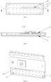
FIG. 1 is a front view of a power battery according to one or more embodiments of the present application. -
FIG. 2 is a side view ofFIG. 1 . -
FIG. 3 is a schematic structural diagram of a battery cover according to one or more embodiments of the present application. -
FIG. 4 is a bottom view ofFIG. 3 . -
FIG. 5 is a cross-sectional view taken along A-A line inFIG. 4 . -
FIG. 6 is an exploded view of the battery cover from one perspective. -
FIG. 7 is an exploded view of the battery cover from another perspective. - In the drawings:
- 1. top cover assembly; 11. cover plate; 12. upper plastic part; 13. lower plastic part; 131. slot; 132. recess; 14. terminal; 141. lower terminal block; 15. insulating cover sheet; 16. insulating plate; 17. liquid injection hole;
- 2. insulating support; 21. first support; 22. second support; 23. notch; 231. rounded corner; 24. fastener; 25. through hole;
- 3. case; 4. core; 41. tab; 5. seal; P. accommodation cavity.
- In the description of the present application, unless otherwise expressly specified and limited, the terms "coupled" "connected" and "fixed" shall be understood in a broad sense, for example, they may be fixed connection, removable connection, or integral. They may be mechanical connection or electrical connection. They may be directly connected or indirectly connected through intermediate medium. They may be internal connection of two elements or interaction of two elements. Those of ordinary skilled in the art may understand the specific meaning of the above terms in the present application in specific circumstances.
- In the present application, unless otherwise expressly specified and defined, a first feature "above" or "below" a second feature may include the first feature directly contacts with the second feature, or it may include the first feature does not directly contact with the second feature but through another feature between them. Also, the first feature "above," "upper" and "over" the second feature includes the first feature directly above and obliquely above the second feature, or merely indicates that the first feature has a higher horizontal height than the second feature. The first feature "below," "lower" and "under" the second feature includes the first feature directly below and obliquely below the second feature, or merely indicates that a horizontal height of the first feature is less than the second feature.
- One or more embodiments of the present application provide a power battery. As shown in
FIGS. 1-5 , the power battery includes acase 3, acore 4 and a battery cover. In addition, one or more embodiments of the present application provide a battery cover including atop cover assembly 1 and an insulatingsupport 2. Thetop cover assembly 1 can be fixedly connected with thecase 3, and thecase 3 and thetop cover assembly 1 form an accommodation space for accommodating thecore 4. Thetop cover assembly 1 can be welded with atab 41 on thecore 4. The insulatingsupport 2 can be accommodated in the accommodation space. The insulatingsupport 2 and thetop cover assembly 1 form an accommodation cavity P for accommodating thetab 41. The insulatingsupport 2 is provided with anotch 23 for thetab 41 to pass through. - When the power battery is provided with the battery cover, the
core 4 and the insulatingsupport 2 are accommodated in the accommodation space. Thetab 41 of thecore 4 is welded with thetop cover assembly 1. Thetab 41 is accommodated in the accommodation cavity P. That is, the accommodation cavity P provides an accommodation space for thetab 41, thereby preventing thetab 41 from being spread between thecore 4 and thetop cover assembly 1. Thus, the structure is stable. In addition, the insulatingsupport 2 effectively isolates thetab 41 from thecore 4, thereby preventing a reshaped part of thetab 41 due to reshaping of thetab 41 from being inserted into thecore 4 backwards. Thus, a short circuit can be avoided, improving safety and reliability of the power battery, and improving the yield rate of the power batteries. - In one or more embodiments, the power battery may a blade battery or another battery.
- In one or more embodiments, as shown in
FIGS. 3 and7 , thetop cover assembly 1 includes acover plate 11, an upperplastic part 12, a lowerplastic part 13, and a terminal 14. Thecover plate 11 can be fixedly connected to thecase 3. The upperplastic part 12 and the lowerplastic part 13 are respectively fixed on opposite sides of thecover plate 11. The lowerplastic part 13 is connected with the insulatingsupport 2. The terminal 14 extends through the lowerplastic part 13, thecover plate 11 and the upperplastic part 12. The terminal 14 can be welded with thetab 41. Thecover plate 11 is generally an aluminum plate. With the upperplastic part 12 and the lowerplastic part 13 arranged, a short circuit can be prevented. In addition, the terminal 14 has a lowerterminal block 141 disposed on a side facing thecore 4. The lowerterminal block 141 has a relatively large cross-sectional area, so as to increase an area of connection with thetab 41 and improve structural reliability. In one or more embodiments, thenotch 23 is disposed toward the lowerterminal block 141 at the end of the terminal 14, so that thetab 41 can pass through thenotch 23 after being welded with the lowerterminal block 141. In one or more embodiments, the lowerplastic part 13 is provided with arecess 132. The lowerplastic part 13 and the insulatingsupport 2 form the accommodation cavity P. In one or more other embodiments, the insulatingsupport 2 may be provided with therecess 132 to form the accommodation cavity P. In one or more yet other embodiments, each of the lowerplastic part 13 and the insulatingsupport 2 may be provided with therecess 132 to form the accommodation cavity P. The arrangement may be determined according to the actual situation and is not limited. For example, the lowerplastic part 13 may not be retained in a region corresponding to the lowerterminal block 141, so as to prevent the lowerplastic part 13 from affecting the welding of the lowerterminal block 141 with thetab 41. In one or more embodiments, the accommodation cavity P is a cuboid-shaped cavity, which increases the accommodation space and facilitates the arrangement of thetab 41. For example, a length of thenotch 23 = the width of thetab 41 + 2-5 mm, and a depth of thenotch 23 = the thickness of thetab 41 + 1-2 mm. - In one or more embodiments, as shown in
FIG. 6 , thenotch 23 is provided with a fillet or arounded corner 231 along a thickness direction of the insulatingsupport 2, so as to avoid forming of a sharp edge at thenotch 23, which can effectively prevent thetab 41 from being cut by the sharp edge in a high-intensity vibration application scenario of thecore 4. By way of example, a size of the fillet or roundedcorner 231 may be, but not limited to, 0.2 mm, 0.4 mm, 0.6 mm, 0.8 mm, or 1.0 mm. - In one or more embodiments, a height of the lower
plastic part 13 is determined according to the thickness of the reshapedtab 41 to be accommodated. The size of the accommodation cavity P is set according to the actual situation, so as to ensure that an energy density can be increased as much as possible under the condition of accommodation of thetab 41. For example, the height of the lowerplastic part 13 = the number of layers of thetab 41 * the thickness of the foil * 3 * a correction coefficient. When apositive tab 41 is to be accommodated, the correction coefficient can be adjusted within a range of 1.5-2.5. When anegative tab 41 is to be accommodated, the correction coefficient can be adjusted within a range of 1.2-2.0. - In one or more embodiments, as shown in
FIG. 6 andFIG. 7 , the insulatingsupport 2 is detachably connected to thetop cover assembly 1, which can prevent the insulatingsupport 2 from falling off during the process of assembling thecore 4, improve the connection stability and reliability, and facilitate disassembly. For example, the insulatingsupport 2 is disposed to cover the lowerplastic part 13, and the insulatingsupport 2 is clamped with the lowerplastic part 13. In one or more embodiments, the lowerplastic part 13 is provided with aslot 131, and the insulatingsupport 2 is provided with afastener 24 that can be clamped to theslot 131. In other embodiments, the insulatingsupport 2 is provided with aslot 131, and the lowerplastic part 13 is provided with afastener 24. For example, a number of groups ofslots 131 and a number of groups offasteners 24 are provided, and the number may be, but not limited to, 4, 6, and 8. Theslots 131 may be symmetrically distributed on opposite sides of the lowerplastic part 13, and thefasteners 24 may be symmetrically distributed on opposite sides of the insulatingsupport 2. - By way of example, the
top cover assembly 1 also includes an insulating sealing ring disposed between the terminal 14 and thecover plate 11 to ensure sealing of the accommodation space and avoid a short circuit. - In one or more embodiments, as shown in
FIG. 3 , thetop cover assembly 1 is provided with aliquid injection hole 17. After thecase 3 and the battery cover are assembled, an electrolyte can be injected into the accommodation space through theliquid injection hole 17 and serves as a channel for ion transfer. By way of example, thetop cover assembly 1 also includes a seal 5 for blocking theinjection hole 17 to prevent leakage of the electrolyte. By way of example, the seal 5 includes sealant plug that match theinjection hole 17 and can be inserted into theinjection hole 17 to enhance the sealing effect of thecore 4, and a sealing aluminum sheet that can be used to weld and seal theinjection hole 17. - In one or more embodiments, as shown in
FIG. 3 , thetop cover assembly 1 further includes an insulatingplate 16 disposed on a side of the upperplastic part 12 away from thecover plate 11 to improve structural reliability. - For example, the
case 3 may be an aluminum case, and thecover plate 11 may be an aluminum plate. Thecover plate 11 is welded with thecase 3. During welding, pre-spot welding is performed. The number of welding spots for pre-spot welding may be, but not limited to, 6EA, 8EA, or 10EA. The welding spots for pre-spot welding are symmetrically distributed. In one or more embodiments, thetop cover assembly 1 further includes an insulatingcover sheet 15 attached to thecover plate 11 to prevent a short circuit between the terminal 14 and thecover plate 11 due to external connection. - In one or more embodiments, the
core 4 is coated with a protective film. An outer surface of thecase 3 is coated with a protective film for insulation. With each of positive andnegative tabs 41 ultrasonically welded, thecore 4 is coated with a protective film to prevent thecore 4 from being scratched when entering the case. The protective film may be of a polymer material with insulation, high temperature resistance and electrolyte corrosion resistance, and can be, but not limited to, a PET (polyethylene terephthalate) sheet with adhesive on one side. - In one or more embodiments, the
tab 41 is coated with protective glue for insulation, so that a short circuit between thetab 41 and thealuminum case 3 can be effectively avoided. Thecore 4 coated with the protective film has an adhesive tape pasted at thetab 41. A width of the adhesive tape exceeds the width of thetab 41 by 2~10 mm. A part of the adhesive tape coated on thecore 4 has a length of 5-25 mm. A part of the adhesive tape coated on thetab 41 has a distance of 0-5 mm from the welding area. The protective glue of thetab 41 can ensure complete insulation at a place where thetab 41 is attached to the aluminum case after the core enters the case. - The
tab 41 of thecore 4 may be laser welded with the corresponding top cover. The length and width of the welding wire are designed according to an overcurrent capacity required by the core to ensure the power requirement of the core. After thetab 41 is welded with the top cover, insulation treatment may be performed on the welding mark area by glue dispensing or adhesive tape pasting. The insulating glue layer or insulating adhesive tape shall be wide enough to completely cover thetab 41 in the width direction and be long enough to completely cover thetab 41 and the laser welding mark in the length direction. - In one or more embodiments, the
core 4 is provided with apositive tab 41 and anegative tab 41. Thecore 4 includes a positive active material, a negative active material, a positive current collector, a negative current collector, and a separator. The active materials provide a solid-phase reaction interface for the electrochemical reaction of the battery. The current collectors after gain/loss of electrons provide an electron channel for electron transfer. The separator can isolate electrons and allow ions to pass through. - In one or more embodiments, a welding mark is provided on the
tab 41. For example, thetab 41 can be flattened by a flat-tooth ultrasonic welding. Compared with deep-tooth welding, the flat-tooth ultrasonic welding will result in a larger welding mark area and a flatter welding mark. Then, the flattenedtab 41 is welded with the lowerterminal block 141 of thetop cover assembly 1 by laser welding, which can enhance the strength of welding between thetab 41 and thetop cover assembly 1, improve an overcurrent capacity of the battery, and has high welding reliability. Thetab 41 of each layer is welded, and the size of the welding mark matches the size of a welding wire used for laser welding of thetab 41 and thecover plate 11. The size of ultrasonic flat welding can be, but not limited to, 10 mm * 20 mm, 15 mm * 20 mm, or 10 mm * 30 mm, and the number of welding marks can be, but not limited to, 1EA, 2EA or 3EA. One welding mark may be adopted if the welding mark area allows. The number of thecores 4 may be, but not limited to, 1EA, 2EA or 3EA. Generally, the number of thecores 4 of a blade battery does not exceed 2EA. - The insulating
support 2 may be mounted after thetab 41 is bent and reshaped, which is beneficial for the insulatingsupport 2 to effectively fix the reshapedtab 41 in the accommodation cavity P formed by the insulatingsupport 2 and the lowerplastic part 13. In one or more embodiments, as shown inFIG. 2 , thetab 41 are bent in a Z-shape in the accommodation cavity P, so that thetab 41 is folded, which is convenient for putting the reshapedtab 41 into the accommodation cavity P when the insulatingsupport 2 is mounted. - In one or more embodiments, the insulating
support 2 abuts against thecore 4 to fix thecore 4, which can ensure that thecore 4 does not shake, thereby improving stability. - In one or more embodiments, as shown in
FIG. 4 , the insulatingsupport 2 includes two support bodies. The two support bodies are both connected to thetop cover assembly 1. Thenotch 23 is formed between the two support bodies. A recess may be provided on only one of the support bodies to form thenotch 23 between the two support bodies. Alternatively, a recess may be provided on each of the support bodies to form thenotch 23 between the two support bodies. Both of the support bodies are detachably connected with the lowerplastic part 13 to improve connection reliability. The two support bodies can be called afirst support 21 and a second support 22, respectively. Thefirst support 21 and the second support 22 may have different sizes, respectively, so that a position where thenotch 23 is formed can be set according to the actual conditions. For example, the position can be set to correspond to a position of the foldedtab 41. For example, thefirst support 21 and the second support 22 may be made of the same material or different materials, respectively. - For example, the insulating
support 2 is made of a material having sufficient hardness and having resistance to electrolyte corrosion and high temperature. The material may be, but not limited to, PP (polypropylene) material. A thickness of the insulatingsupport 2 may be, but not limited to, 0.5 mm, 1.0 mm, 1.5 mm or 2.0 mm. The height of the insulatingsupport 2 matches the height of the lowerplastic part 13. For example, as shown inFIG. 4 , the insulatingsupport 2 is provided with throughholes 25 communicating with the accommodation cavity P. Each throughhole 25 may be, but not limited to, in a circular shape or a square shape. The through holes 25 are designed to facilitate free flow of the electrolyte in the inner space of the core. - One or more embodiments provide a process of manufacturing a
core 4, including the following steps. In the first step of homogenizing positive and negative electrodes, the positive active material, the negative active material, a conductive agent and a binder are uniformly dispersed into a solvent at a certain mass ratio. In the second step of coating the positive and negative electrodes, the uniformly dispersed positive and negative electrode slurry is stably coated on positive and negative current collectors. In the third step of preparing positive and negative electrode sheets, the coated positive and negative electrode sheets are rolled to the specified thickness and then cut to a specified size. In the fourth step of winding (or laminating) and assembling, the prepared positive and negative electrode sheets are wound (or laminated) into thecore 4 that is then assembled into a battery. In the fifth step of baking, the assembled battery is baked in the vacuum oven to the specified moisture value. In the sixth step of injection, the electrolyte is injected into the battery, and then the battery is let stand until the electrolyte completely infiltrates the electrode sheets. In the seventh step of formation, the battery is activated, and the gas generated by side reaction in the battery is discharged by pumping negative pressure. In the eighth step of dividing the capacity, the formed battery is sealed and welded, and the capacity is divided according to the preset process. - One or more embodiments provide a process of assembling a power battery, including the following steps S1-S13.
- At step S1, a
positive tab 41 and anegative tab 41 of acore 4 are respectively welded through flat-tooth ultrasonic welding process. - At step S2, the
core 4 is coated with a protective film. - At step S3, the
positive tab 41 and thenegative tab 41 are pasted with protective glue. - At step S4, the
tab 41 is welded and glued to a top cover (it may be thepositive tab 41 or thenegative tab 41 first). - At step S5, the welded
tab 41 is bent and reshaped in a Z-shape. - At step S6, the insulating
support 2 is mounted. Thefirst support 21 and the second support 22 of the insulatingsupport 2 are successively clamped to the lowerplastic part 13, and the reshaped part of thetab 41 is completely accommodated in the cavity formed by the two support bodies and the lowerplastic part 13 and is completely isolated from thecore 4. - At step S7, the
core 4 with the insulatingsupport 2 is put intocase 3. - At step S8, the
top cover assembly 1 is fitted to thecase 3 to close thecase 3, and thecover plate 11 is fixed to thecase 3 by pre-spot welding with laser. - At step S9, the
tab 41 on an other side of thecore 4 is laser welded to thetop cover assembly 1 and then the welding mark glue is pasted to completely cover the welding mark and thetab 41. - At step S10, the welded
tab 41 is bent and reshaped in a Z-shape, so that thetab 41 is folded. - At step S11, the insulating
support 2 is mounted. Thefirst support 21 and the second support 22 of the insulatingsupport 2 are successively clamped to the lowerplastic part 13, so that thefastener 24 of the insulatingsupport 2 is completely clamped into theslot 131 of the lowerplastic part 13, and the reshaped part of thetab 41 is completely accommodated in the accommodation cavity P formed by the insulatingsupport 2 and the lowerplastic part 13 and is completely isolated from thecore 4. - At step S12, the
top cover assembly 1 is fitted to thecase 3 to close thecase 3, and thecover plate 11 is fixed to thecase 3 by pre-spot welding with laser. The number of welding spots may be consistent with the number of spots of the above-mentioned pre-spot welding for thecover plate 11. - At
step S 13, thecover plate 11 of the positive and negative electrodes of the core are fully welded to thecase 3 by laser welding so as to ensure that the welding area is completely sealed.
Claims (14)
- A battery cover, characterized by comprising:a top cover assembly (1) capable of being fixedly connected with a case (3) to form an accommodation space for accommodating a core (4), and capable of being welded with a tab (41) on the core (4); andan insulating support (2) capable of being accommodated in the accommodation space, wherein the insulating support (2) and the top cover assembly (1) form an accommodation cavity (P) for accommodating the tab (41), and the insulating support (2) is provided with a notch (23) for the tab (41) to pass through.
- The battery cover according to claim 1, characterized in that the insulating support (2) is detachably connected to the top cover assembly (1).
- The battery cover according to claim 1, characterized in that the insulating support (2) comprises two support bodies each connected with the top cover assembly (1), and the notch (23) is formed between the two support bodies.
- The battery cover according to claim 1, characterized in that the notch (23) is provided with a fillet or rounded corner (231) along a thickness direction of the insulating support (2).
- The battery cover according to claim 1, characterized in that a welding mark is provided on the tab (41), and the welding mark is coated with insulating glue.
- The battery cover according to claim 1, characterized in that the accommodation cavity (P) is a cuboid-shaped cavity.
- The battery cover according to claim 1, characterized in that the tab (41) is bent in a Z-shape in the accommodation cavity (P).
- The battery cover according to claim 1, characterized in that the insulating support (2) is arranged to abut against the core (4).
- The battery cover according to claim 1, characterized in that the insulating support (2) is provided with a through hole (25) communicating with the accommodation cavity (P).
- The battery cover according to claim 1, characterized in thatthe core (4) is coated with a protective film; and/oran outer surface of the case (3) is coated with a protective film; and/orthe tab (41) is pasted with protective glue.
- The battery cover according to any one of claims 1-10, characterized in that the top cover assembly (1) comprises:a cover plate (11) capable of being fixedly connected with the case (3);an upper plastic part (12) and a lower plastic part (13) fixed respectively on opposite sides of the cover plate (11), the lower plastic part (13) being connected with the insulating support (2); anda terminal (14) extending through the upper plastic part (12), the cover plate (11) and the lower plastic part (13), and being capable of being welded with the tab (41).
- The battery cover according to claim 11, characterized in that at least one of the lower plastic part (13) and the insulating support (2) is provided with a recess (132), and the accommodation cavity (P) is formed by the lower plastic part (13) and the insulating support (2).
- The battery cover according to claim 11, characterized in that the notch (23) is disposed toward a lower terminal block (141) at an end of the terminal (14).
- A power battery, characterized by comprising a case (3), a core (4) and the battery cover according to any one of claims 1-13, wherein the core (4) and the insulating support (2) are accommodated in the accommodation space, the tab (41) of the core (4) is welded with the top cover assembly (1), and the tab (41) is accommodated in the accommodation cavity (P).
Applications Claiming Priority (2)
| Application Number | Priority Date | Filing Date | Title |
|---|---|---|---|
| CN202222673198.2U CN218472105U (en) | 2022-10-11 | 2022-10-11 | Battery cover and power battery |
| PCT/CN2022/126555 WO2024077653A1 (en) | 2022-10-11 | 2022-10-21 | Battery cover plate and power battery |
Publications (2)
| Publication Number | Publication Date |
|---|---|
| EP4376204A1 true EP4376204A1 (en) | 2024-05-29 |
| EP4376204A4 EP4376204A4 (en) | 2024-10-23 |
Family
ID=85146025
Family Applications (1)
| Application Number | Title | Priority Date | Filing Date |
|---|---|---|---|
| EP22929207.3A Pending EP4376204A4 (en) | 2022-10-11 | 2022-10-21 | BATTERY COVER PLATE AND POWER BATTERY |
Country Status (5)
| Country | Link |
|---|---|
| US (1) | US20240234986A9 (en) |
| EP (1) | EP4376204A4 (en) |
| JP (1) | JP7690046B2 (en) |
| CN (1) | CN218472105U (en) |
| WO (1) | WO2024077653A1 (en) |
Families Citing this family (2)
| Publication number | Priority date | Publication date | Assignee | Title |
|---|---|---|---|---|
| MX2025011174A (en) * | 2023-06-01 | 2025-10-01 | Eve Power Co Ltd | Prismatic battery and welding method |
| CN116944720B (en) * | 2023-08-31 | 2026-04-07 | 上海轩邑新能源发展有限公司 | A method for irregular welding of lithium batteries and lithium batteries |
Family Cites Families (14)
| Publication number | Priority date | Publication date | Assignee | Title |
|---|---|---|---|---|
| JP3891047B2 (en) * | 2002-06-10 | 2007-03-07 | 松下電器産業株式会社 | battery |
| JP4780598B2 (en) * | 2004-09-29 | 2011-09-28 | 日立マクセルエナジー株式会社 | Sealed prismatic battery |
| KR100807029B1 (en) * | 2006-03-28 | 2008-02-25 | 삼성에스디아이 주식회사 | Secondary battery |
| KR101602012B1 (en) * | 2013-01-18 | 2016-03-17 | 주식회사 엘지화학 | Secondary battery structure |
| KR102283782B1 (en) * | 2014-11-26 | 2021-07-30 | 삼성에스디아이 주식회사 | Rechargeable battery |
| KR102053560B1 (en) * | 2015-12-24 | 2019-12-06 | 가부시키가이샤 도요다 지도숏키 | Power storage device |
| CN109659454B (en) * | 2017-10-10 | 2020-11-10 | 宁德时代新能源科技股份有限公司 | Top cover assembly of secondary battery and secondary battery |
| CN208189697U (en) * | 2018-03-23 | 2018-12-04 | 比亚迪股份有限公司 | Single battery, battery modules, power battery and electric car |
| CN207938708U (en) * | 2018-04-10 | 2018-10-02 | 深圳市比克动力电池有限公司 | A power battery top cover insulation structure |
| CN208862096U (en) * | 2018-08-21 | 2019-05-14 | 东莞塔菲尔新能源科技有限公司 | A kind of assembling structure of power battery top cover and battery core |
| CN209029420U (en) * | 2018-08-21 | 2019-06-25 | 东莞塔菲尔新能源科技有限公司 | The assembling structure of power battery top cover and battery core |
| CN111276732A (en) * | 2020-03-30 | 2020-06-12 | 湖北亿纬动力有限公司 | A single battery and battery module |
| JP2022073498A (en) * | 2020-11-02 | 2022-05-17 | プライムプラネットエナジー&ソリューションズ株式会社 | Square secondary battery and manufacturing method thereof |
| CN114447525B (en) * | 2022-01-28 | 2024-03-22 | 天津市捷威动力工业有限公司 | Battery with double-side tabs and assembling method thereof |
-
2022
- 2022-10-11 CN CN202222673198.2U patent/CN218472105U/en active Active
- 2022-10-21 JP JP2023552514A patent/JP7690046B2/en active Active
- 2022-10-21 WO PCT/CN2022/126555 patent/WO2024077653A1/en not_active Ceased
- 2022-10-21 EP EP22929207.3A patent/EP4376204A4/en active Pending
-
2023
- 2023-09-05 US US18/242,374 patent/US20240234986A9/en active Pending
Also Published As
| Publication number | Publication date |
|---|---|
| JP7690046B2 (en) | 2025-06-09 |
| US20240234986A9 (en) | 2024-07-11 |
| US20240136681A1 (en) | 2024-04-25 |
| JP2024537947A (en) | 2024-10-18 |
| CN218472105U (en) | 2023-02-10 |
| EP4376204A4 (en) | 2024-10-23 |
| WO2024077653A1 (en) | 2024-04-18 |
Similar Documents
| Publication | Publication Date | Title |
|---|---|---|
| EP3709392B1 (en) | Secondary battery | |
| EP3531474B1 (en) | Button battery and manufacturing method therefor | |
| EP2587566B1 (en) | Rechargeable battery with improved safety | |
| EP2136429B1 (en) | Electrode assembly and lithium secondary battery with same | |
| EP2325929B1 (en) | Secondary battery and method of manufacture | |
| KR102938528B1 (en) | Batteries and electronics | |
| US7781092B2 (en) | Secondary battery and method of manufacturing same | |
| CN112913076A (en) | Smart battery and its lithium battery | |
| KR100515833B1 (en) | Jelly-roll type electrode assembly and secondary battery applying the same | |
| US20240136681A1 (en) | Battery covers and power batteries | |
| US20200381765A1 (en) | Battery | |
| CN213150818U (en) | Battery tab rubberizing structure | |
| WO2021012912A1 (en) | Top cover assembly, secondary battery, and apparatus using battery | |
| CN113113738A (en) | Multi-tab battery | |
| CN115966852B (en) | Battery | |
| CN112803125A (en) | Tab, soft-package button type lithium ion battery and manufacturing method thereof | |
| CN116387638A (en) | Cylindrical battery and manufacturing method thereof | |
| CN212380471U (en) | Hard shell button cell | |
| KR100858807B1 (en) | Pouch Type Case and Lithium Secondary Battery | |
| CN215119175U (en) | Multi-tab battery | |
| EP4027438A1 (en) | Pouch packaged lithium-ion battery with tooth-shaped sealing edge | |
| CN113812016B (en) | Pole piece, electrode assembly, battery and power utilization device applying same | |
| KR101095343B1 (en) | Jelly-roll with improved structure and secondary battery comprising the same | |
| CN222705574U (en) | Laminated cell and battery | |
| CN223378206U (en) | Battery cell structure |
Legal Events
| Date | Code | Title | Description |
|---|---|---|---|
| STAA | Information on the status of an ep patent application or granted ep patent |
Free format text: STATUS: UNKNOWN |
|
| STAA | Information on the status of an ep patent application or granted ep patent |
Free format text: STATUS: THE INTERNATIONAL PUBLICATION HAS BEEN MADE |
|
| PUAI | Public reference made under article 153(3) epc to a published international application that has entered the european phase |
Free format text: ORIGINAL CODE: 0009012 |
|
| STAA | Information on the status of an ep patent application or granted ep patent |
Free format text: STATUS: REQUEST FOR EXAMINATION WAS MADE |
|
| 17P | Request for examination filed |
Effective date: 20230906 |
|
| AK | Designated contracting states |
Kind code of ref document: A1 Designated state(s): AL AT BE BG CH CY CZ DE DK EE ES FI FR GB GR HR HU IE IS IT LI LT LU LV MC ME MK MT NL NO PL PT RO RS SE SI SK SM TR |
|
| REG | Reference to a national code |
Ref country code: DE Ref legal event code: R079 Free format text: PREVIOUS MAIN CLASS: H01M0050502000 Ipc: H01M0050147000 |
|
| A4 | Supplementary search report drawn up and despatched |
Effective date: 20240924 |
|
| RIC1 | Information provided on ipc code assigned before grant |
Ipc: H01M 50/536 20210101ALN20240918BHEP Ipc: H01M 50/531 20210101ALN20240918BHEP Ipc: H01M 50/593 20210101ALI20240918BHEP Ipc: H01M 50/553 20210101ALI20240918BHEP Ipc: H01M 50/59 20210101ALI20240918BHEP Ipc: H01M 50/586 20210101ALI20240918BHEP Ipc: H01M 50/55 20210101ALI20240918BHEP Ipc: H01M 50/533 20210101ALI20240918BHEP Ipc: H01M 50/528 20210101ALI20240918BHEP Ipc: H01M 50/516 20210101ALI20240918BHEP Ipc: H01M 50/502 20210101ALI20240918BHEP Ipc: H01M 50/176 20210101ALI20240918BHEP Ipc: H01M 50/15 20210101ALI20240918BHEP Ipc: H01M 50/147 20210101AFI20240918BHEP |
|
| DAV | Request for validation of the european patent (deleted) | ||
| DAX | Request for extension of the european patent (deleted) |