EP4376185A1 - Battery pack and method of assembling the same - Google Patents
Battery pack and method of assembling the same Download PDFInfo
- Publication number
- EP4376185A1 EP4376185A1 EP23189370.2A EP23189370A EP4376185A1 EP 4376185 A1 EP4376185 A1 EP 4376185A1 EP 23189370 A EP23189370 A EP 23189370A EP 4376185 A1 EP4376185 A1 EP 4376185A1
- Authority
- EP
- European Patent Office
- Prior art keywords
- fixing bracket
- pack
- cell stacks
- battery cells
- disposed
- Prior art date
- Legal status (The legal status is an assumption and is not a legal conclusion. Google has not performed a legal analysis and makes no representation as to the accuracy of the status listed.)
- Granted
Links
Images



Classifications
-
- H—ELECTRICITY
- H01—ELECTRIC ELEMENTS
- H01M—PROCESSES OR MEANS, e.g. BATTERIES, FOR THE DIRECT CONVERSION OF CHEMICAL ENERGY INTO ELECTRICAL ENERGY
- H01M50/00—Constructional details or processes of manufacture of the non-active parts of electrochemical cells other than fuel cells, e.g. hybrid cells
- H01M50/20—Mountings; Secondary casings or frames; Racks, modules or packs; Suspension devices; Shock absorbers; Transport or carrying devices; Holders
- H01M50/204—Racks, modules or packs for multiple batteries or multiple cells
- H01M50/207—Racks, modules or packs for multiple batteries or multiple cells characterised by their shape
- H01M50/209—Racks, modules or packs for multiple batteries or multiple cells characterised by their shape adapted for prismatic or rectangular cells
-
- H—ELECTRICITY
- H01—ELECTRIC ELEMENTS
- H01M—PROCESSES OR MEANS, e.g. BATTERIES, FOR THE DIRECT CONVERSION OF CHEMICAL ENERGY INTO ELECTRICAL ENERGY
- H01M10/00—Secondary cells; Manufacture thereof
- H01M10/04—Construction or manufacture in general
- H01M10/0404—Machines for assembling batteries
-
- H—ELECTRICITY
- H01—ELECTRIC ELEMENTS
- H01M—PROCESSES OR MEANS, e.g. BATTERIES, FOR THE DIRECT CONVERSION OF CHEMICAL ENERGY INTO ELECTRICAL ENERGY
- H01M10/00—Secondary cells; Manufacture thereof
- H01M10/04—Construction or manufacture in general
- H01M10/0481—Compression means other than compression means for stacks of electrodes and separators
-
- H—ELECTRICITY
- H01—ELECTRIC ELEMENTS
- H01M—PROCESSES OR MEANS, e.g. BATTERIES, FOR THE DIRECT CONVERSION OF CHEMICAL ENERGY INTO ELECTRICAL ENERGY
- H01M10/00—Secondary cells; Manufacture thereof
- H01M10/60—Heating or cooling; Temperature control
- H01M10/61—Types of temperature control
- H01M10/613—Cooling or keeping cold
-
- H—ELECTRICITY
- H01—ELECTRIC ELEMENTS
- H01M—PROCESSES OR MEANS, e.g. BATTERIES, FOR THE DIRECT CONVERSION OF CHEMICAL ENERGY INTO ELECTRICAL ENERGY
- H01M10/00—Secondary cells; Manufacture thereof
- H01M10/60—Heating or cooling; Temperature control
- H01M10/64—Heating or cooling; Temperature control characterised by the shape of the cells
- H01M10/647—Prismatic or flat cells, e.g. pouch cells
-
- H—ELECTRICITY
- H01—ELECTRIC ELEMENTS
- H01M—PROCESSES OR MEANS, e.g. BATTERIES, FOR THE DIRECT CONVERSION OF CHEMICAL ENERGY INTO ELECTRICAL ENERGY
- H01M10/00—Secondary cells; Manufacture thereof
- H01M10/60—Heating or cooling; Temperature control
- H01M10/65—Means for temperature control structurally associated with the cells
- H01M10/655—Solid structures for heat exchange or heat conduction
- H01M10/6554—Rods or plates
-
- H—ELECTRICITY
- H01—ELECTRIC ELEMENTS
- H01M—PROCESSES OR MEANS, e.g. BATTERIES, FOR THE DIRECT CONVERSION OF CHEMICAL ENERGY INTO ELECTRICAL ENERGY
- H01M50/00—Constructional details or processes of manufacture of the non-active parts of electrochemical cells other than fuel cells, e.g. hybrid cells
- H01M50/20—Mountings; Secondary casings or frames; Racks, modules or packs; Suspension devices; Shock absorbers; Transport or carrying devices; Holders
- H01M50/244—Secondary casings; Racks; Suspension devices; Carrying devices; Holders characterised by their mounting method
-
- H—ELECTRICITY
- H01—ELECTRIC ELEMENTS
- H01M—PROCESSES OR MEANS, e.g. BATTERIES, FOR THE DIRECT CONVERSION OF CHEMICAL ENERGY INTO ELECTRICAL ENERGY
- H01M50/00—Constructional details or processes of manufacture of the non-active parts of electrochemical cells other than fuel cells, e.g. hybrid cells
- H01M50/20—Mountings; Secondary casings or frames; Racks, modules or packs; Suspension devices; Shock absorbers; Transport or carrying devices; Holders
- H01M50/262—Mountings; Secondary casings or frames; Racks, modules or packs; Suspension devices; Shock absorbers; Transport or carrying devices; Holders with fastening means, e.g. locks
- H01M50/264—Mountings; Secondary casings or frames; Racks, modules or packs; Suspension devices; Shock absorbers; Transport or carrying devices; Holders with fastening means, e.g. locks for cells or batteries, e.g. straps, tie rods or peripheral frames
-
- H—ELECTRICITY
- H01—ELECTRIC ELEMENTS
- H01M—PROCESSES OR MEANS, e.g. BATTERIES, FOR THE DIRECT CONVERSION OF CHEMICAL ENERGY INTO ELECTRICAL ENERGY
- H01M50/00—Constructional details or processes of manufacture of the non-active parts of electrochemical cells other than fuel cells, e.g. hybrid cells
- H01M50/20—Mountings; Secondary casings or frames; Racks, modules or packs; Suspension devices; Shock absorbers; Transport or carrying devices; Holders
- H01M50/289—Mountings; Secondary casings or frames; Racks, modules or packs; Suspension devices; Shock absorbers; Transport or carrying devices; Holders characterised by spacing elements or positioning means within frames, racks or packs
-
- H—ELECTRICITY
- H01—ELECTRIC ELEMENTS
- H01M—PROCESSES OR MEANS, e.g. BATTERIES, FOR THE DIRECT CONVERSION OF CHEMICAL ENERGY INTO ELECTRICAL ENERGY
- H01M50/00—Constructional details or processes of manufacture of the non-active parts of electrochemical cells other than fuel cells, e.g. hybrid cells
- H01M50/50—Current conducting connections for cells or batteries
- H01M50/502—Interconnectors for connecting terminals of adjacent batteries; Interconnectors for connecting cells outside a battery casing
-
- H—ELECTRICITY
- H01—ELECTRIC ELEMENTS
- H01M—PROCESSES OR MEANS, e.g. BATTERIES, FOR THE DIRECT CONVERSION OF CHEMICAL ENERGY INTO ELECTRICAL ENERGY
- H01M50/00—Constructional details or processes of manufacture of the non-active parts of electrochemical cells other than fuel cells, e.g. hybrid cells
- H01M50/50—Current conducting connections for cells or batteries
- H01M50/502—Interconnectors for connecting terminals of adjacent batteries; Interconnectors for connecting cells outside a battery casing
- H01M50/507—Interconnectors for connecting terminals of adjacent batteries; Interconnectors for connecting cells outside a battery casing comprising an arrangement of two or more busbars within a container structure, e.g. busbar modules
-
- Y—GENERAL TAGGING OF NEW TECHNOLOGICAL DEVELOPMENTS; GENERAL TAGGING OF CROSS-SECTIONAL TECHNOLOGIES SPANNING OVER SEVERAL SECTIONS OF THE IPC; TECHNICAL SUBJECTS COVERED BY FORMER USPC CROSS-REFERENCE ART COLLECTIONS [XRACs] AND DIGESTS
- Y02—TECHNOLOGIES OR APPLICATIONS FOR MITIGATION OR ADAPTATION AGAINST CLIMATE CHANGE
- Y02E—REDUCTION OF GREENHOUSE GAS [GHG] EMISSIONS, RELATED TO ENERGY GENERATION, TRANSMISSION OR DISTRIBUTION
- Y02E60/00—Enabling technologies; Technologies with a potential or indirect contribution to GHG emissions mitigation
- Y02E60/10—Energy storage using batteries
Definitions
- the present disclosure relates to a battery pack and a method of assembling the same.
- a secondary battery refers to a battery capable of repeated charging and discharging because mutual conversion between chemical energy and electrical energy is reversible.
- Such a secondary battery may be used as an energy source for electric vehicles, hybrid vehicles, energy storage systems (ESSs), and the like, which have recently attracted attention, including use in mobile devices.
- ESSs energy storage systems
- the secondary battery may be used in a form in which one or more battery cells made of a flexible pouch-type battery cell or a prismatic or cylindrical can-type battery cell having rigidity are electrically connected, and in particular, in the case of an electric vehicle requiring high-output power characteristics, it may be used in a form of a battery module in which one or more cell stacks (in which a plurality of battery cells are stacked) are electrically connected or a battery pack in which one or more battery modules are electrically connected.
- a battery pack includes a housing accommodating one or more battery modules, and the battery module includes a housing accommodating one or more battery cells, separately from the housing of the battery pack. Accordingly, conventional battery packs have redundant components performing the same function, which is disadvantageous in terms of productivity and weight reduction of the battery pack.
- One aspect of the present disclosure is to provide a battery pack whose configuration is simplified as a whole by omitting redundant components even though the same function is performed, and a method of assembling the same.
- a battery pack may include: a plurality of cell stacks including a plurality of battery cells; a pack housing accommodating the plurality of cell stacks; at least one fixing bracket disposed both between the plurality of cell stacks and the pack housing and between two adjacent cell stacks of the plurality of cell stacks; and a fastening member fastening the fixing bracket to the pack housing, wherein the at least one fixing bracket may be disposed to contact the plurality of battery cells on an upper side of the plurality of cell stacks.
- the at least one fixing bracket may include: a first fixing bracket disposed to overlap one of the plurality of cell stacks; and a second fixing bracket disposed to overlap the two adjacent cell stacks.
- the first fixing bracket and the second fixing bracket may have a length of the plurality of battery cells in a stacking direction, and each of the first fixing bracket and the second fixing bracket may include a fastening portion through which the fastening member passes and an extension portion extending from the fastening portion to cover the upper side of the plurality of battery cells.
- the first fixing bracket may include only one extension portion, and the second fixing bracket may include two extension portions.
- the battery pack may further include a support member disposed between the plurality of battery cells and the housing to cover both sides of the plurality of battery cells.
- one surface of the support member facing the pack housing may include a plurality of protrusions and a plurality of insertion grooves, alternately formed, and the plurality of insertion grooves may be disposed between the plurality of protrusions.
- one surface of the support member facing the pack housing may be disposed in an inclined shape so that a thickness decreases from an upper side to a lower side of the support member, and the pack housing may be formed in a shape corresponding thereto.
- the battery pack may further include a compression member disposed between at least two of the plurality of battery cells.
- the plurality of battery cells comprising the plurality of cell stacks may be prismatic battery cells including an electrode terminal on one side of the plurality of battery cells.
- the battery pack may further include a bus bar a) a) disposed on a side of one surface of the plurality of battery cells provided with the electrode terminal and b) electrically connected to the electrode terminal; and a bus bar assembly including a bus bar frame on which the bus bar is disposed.
- the battery pack may further include a cooling plate disposed to face the bus bar assembly and under the plurality of cell stacks.
- the battery pack may further include a pack cover coupled to the pack housing and covering the plurality of cell stacks.
- a method of assembling a battery pack may include: a first operation of transferring a plurality of cell stacks including a plurality of battery cells stacked in one direction and a support member disposed to cover the plurality of battery cells in a stacking direction of the plurality of battery cells to a pack housing; a second operation of disposing a fixing bracket between the plurality of cell stacks and the pack housing and between the plurality of cell stacks; and a third operation of fixing the plurality of cell stacks to the pack housing by fastening a fastening member to penetrate through the fixing bracket and the pack housing, wherein in the second operation, the fixing bracket may be disposed to contact the plurality of battery cells on an upper side of the plurality of cell stacks.
- the plurality of cell stacks may be transferred to the pack housing by a lifting device, and the support member may include a plurality of insertion grooves into which legs of the lifting device are inserted.
- a compression member may be disposed between at least the plurality of battery cells, to absorb pressure applied in a direction in which the plurality of battery cells are stacked when the plurality of cell stacks are transferred.
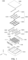
- FIG. 1 is an exploded perspective view of a battery pack according to one embodiment of the present disclosure.
- a battery pack 1000 may include a pack housing 1010, a plurality of cell stacks (or battery module) 1100 accommodated in the pack housing 1010, and a pack cover 1020 coupled to the pack housing 1010 to cover the plurality of cell stacks 1100.
- the pack housing 1010 and the pack cover 1020 forming an exterior of the battery pack 1000 may be formed of a material containing aluminum.
- the pack housing 1010 may form an inner space in which a plurality of cell stacks 1100 are accommodated.
- the inner space of the pack housing 1010 may be partitioned into a plurality of spaces so that the plurality of cell stacks 1100 can be individually disposed.
- a sidewall 1011 may be formed in the pack housing 1010 to penetrate through an inner space, and the inner space may be partitioned or divided into a plurality of spaces by the sidewall 1011. Each of the cell stacks 1100 may be individually disposed in one of the spaces, partitioned by the sidewall 1011.
- the sidewall 1011 may have a shape extending in a Y-direction, and as the sidewall 1011 is disposed, the inner space may be partitioned in an X-direction.
- the plurality of cell stacks 1100 may be disposed in respective spaces, partitioned in the X-direction.
- a pack cover 1020 may be coupled to an upper portion of the pack housing 1010 in a state in which the plurality of cell stacks 1100 are disposed in the inner space.
- the pack cover 1020 may be coupled to the pack housing 1010 to completely cover the inner space.
- the plurality of cell stacks 1100 disposed in the inner space may be protected from external impacts by the pack cover 1020.
- the plurality of cell stacks 1100 may include a plurality of battery cells 1110 arranged in one direction.
- the plurality of cell stacks 1100 may include a plurality of battery cells 1110 arranged in a Y-direction.
- a support member 1140 supporting the plurality of battery cells 1110 may be disposed outside the plurality of battery cells 1110.
- the support member 1140 may support the plurality of battery cells 1110 in the Y-direction in which the plurality of battery cells 1110 are arranged. A description related to the support member 1140 will be described later.
- the plurality of battery cells 1110 may be prismatic battery cells 1110. That is, the battery module 1100 may include a plurality of prismatic battery cells 1110 arranged in a Y-direction. The plurality of prismatic battery cells 1110 may be arranged in the Y-direction so that wide surfaces thereof face each other.
- the prismatic battery cell may refer to a battery cell in which a case 1111 accommodating an electrode assembly and an electrolyte has a flat and angular shape, and the case 1111 may be made of aluminum.
- the plurality of prismatic battery cells 1110 may have positive and negative electrode terminals (or electrode terminals) protruding to one side thereof for example in a height direction (e.g., Z-direction).
- the positive electrode terminal 1112 and the negative electrode terminal 1113 may be provided to be spaced apart from each other in a length direction (e.g., X-direction) of the battery cell 1110.
- the plurality of battery cells 1110 may be electrically connected to neighboring battery cells 1110 through an electrode terminal.
- a vent portion 1115 may be provided in the case 1111 between the positive electrode terminal 1112 and the negative electrode terminal 1113.
- the vent portion 115 may be a passage through which gas generated inside the case 1111 is discharged.
- a bus bar assembly 1200 may be disposed on an upper side of the plurality of cell stacks 1100.
- the bus bar assembly 1200 may (as shown in FIG. 1 ) include a bus bar 1210 electrically connected to an electrode terminal and a bus bar frame 1220 on which the bus bar 1210 is disposed.
- the bus bar assembly 1200 may include a flexible printed circuit board (FPCB) 1230 (as shown in FIG. 1 ) electrically connected to the bus bar 1210 and receiving a voltage, temperature information, and the like, of the plurality of battery cells 1110.
- FPCB flexible printed circuit board
- the bus bar frame 1220 may extend in a longitudinal direction (Y-direction based on the drawing) of the cell stack 1100, and may overlap the plurality of battery cells 1110 on an upper side of the battery module 1100.
- a portion of both sides of the plurality of battery cells 1110 in the longitudinal direction may not overlap the bus bar frame 1220 (in this case, the positive electrode terminal 1112 and the negative electrode terminal 1113 of at least the plurality of battery cells 1110 may overlap the bus bar frame 1220), and the corresponding portion may overlap a fixing bracket 1300 to be described later. That is, a bus bar assembly 1200 and a fixing bracket 1300 may be disposed on an upper side of the cell stack 1100 according to one embodiment of the present disclosure.
- the bus bar frame 1220 may include a hole exposing electrode terminals 1112 and 1113 of the plurality of battery cells 1110 and vent portion 1115, and the bus bar 1210 may be electrically connected to the electrode terminals 1112 and 1113 exposed through the hole.
- the bus bar 1210 may electrically connect electrode terminals 1112 and 1113 of neighboring battery cells 1110.
- a plurality of battery cells 1110 as illustrated are connected in series through the bus bar, but this embodiment thereof is not limited thereto, and various connection structures may be employed as needed.
- a fixing bracket 1300 may be disposed on an upper side of the plurality of cell stacks 1100.
- the fixing bracket 1300 may be a component fixing and coupling the cell stack 1100 to the battery pack 1000.
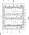
- FIG. 2 is a plan view illustrating an assembled state of the battery pack according to one embodiment of the present disclosure
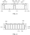
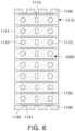
- FIGS. 3 and 4 are side views illustrating an assembled state of the battery pack according to one embodiment of the present disclosure.
- the cell stack 1100 may not include a housing or top cover closing the plurality of battery cells 1110 except for the support member 1140. Accordingly, the plurality of battery cells 1110 may be directly fixed and coupled to the pack housing 1010.
- the fixing bracket 1300 may be disposed to simultaneously overlap the plurality of cell stacks 1100 and the pack housing 1010 (including the side walls 1011).
- the fixing bracket 1300 may have a length in an X-direction so as to cover the cell stack 1100 and the pack housing 1010 at the same time, and may have a length in a Y-direction so as to overlap the plurality of battery cells 1110 included in the cell stack 1100 at the same time.
- Both sides of the plurality of cell stacks 1100 may be supported by the fixing brackets 1300.
- the fixing bracket 1300 may be disposed between the cell stack 1100 and the pack housing 1010 and between the plurality of cell stacks 1100. While the fixing bracket 1300 illustrated in FIGs. 1 and 2 comprises separate elements 1310, 1320, these elements 1310 and 1320 may be connected together or otherwise comprise a unitary piece.
- the fixing bracket 1300 may include a first fixing bracket 1310 and a second fixing bracket 1320 which, in order to distinguish them from the fixing bracket 1300, may also be referred to as fixing bracket elements (1310, 1320).
- the first fixing bracket 1310 (first fixing bracket element 1310) may be a fixing bracket (fixing bracket element) disposed between the cell stack 1100 and the pack housing 1010
- the second fixing bracket 1320 (second fixing bracket element 1320) may be a fixing bracket (fixing bracket element) disposed between the plurality of cell stacks 1100.
- the fixing bracket 1300 may include two first fixing brackets 1310 (first fixing bracket elements 1310) and one or more second fixing brackets 1320 (second fixing bracket elements 1320) . Since the first fixing bracket 1310 (first fixing bracket element 1310) is disposed between the cell stack 1100 and the pack housing 1010, two first fixing brackets 1310 (first fixing bracket elements 1310) may be provided. Meanwhile, a different number of second fixing brackets 1320 (second fixing bracket elements 1320) disposed between the plurality of cell stacks 1100 may be provided according to the number of the plurality of cell stacks 1100. For example, when the battery pack 1000 includes n cell stacks 1100, n-1 second fixing brackets 1320 (second fixing bracket elements 1320) may be provided.
- the first fixing bracket 1310 (first fixing bracket element 1310) and the second fixing bracket 1320 (second fixing bracket element 1320) may include extension portions 1312 and 1322 disposed on an upper side of the cell stack 1100.
- first fixing bracket 1310 first fixing bracket element 1310
- second fixing bracket 1320 second fixing bracket element 1320
- fastening portions 1311 and 1321 disposed on the upper side of the pack housing 1010 or the side wall 1011
- extension portions 1312 and 1322 disposed to overlap the upper side of the cell stack 1100.
- the fastening portions 1311 and 1321 may have a thickness to compensate for a height difference between the pack housing 1010 or the side wall 1011 and the cell stack 1100.
- the fastening portions 1311 and 1321 may be formed with a plurality of through-holes 1313 and 1323 into which a fastening member 1400 is inserted in a longitudinal direction.
- the fastening member 1400 may be fastened to the pack housing 1010 in the z direction.
- multiple fastening members 1400 are inserted into the through-holes 1313 and 1323 in fixing brackets 1310 and 1320 (fixing bracket elements 1310 and 1320) .
- the side wall 1011 of the pack housing 1010 may include a fastening hole 1012 (shown in FIG. 1 ) in which the fastening member 1400 is accommodated and fastened, and the fastening member 1400 may be fastened to the pack housing 1010 while being inserted into the fastening hole 1012.
- the extension portions 1312 and 1322 may be portions extending from the fastening portions 1311 and 1321 in the X-direction.
- the first fixing bracket 1310 (first fixing bracket element 1310) and the second fixing bracket 1320 (second fixing bracket element 1320) may be disposed so that the extension portions 1312 and 1322 are placed toward the battery module 1100, and the extension portions 1312 and 1322 may be disposed to overlap a portion of the cell stacks 1100 on the upper side of the cell stack 1100.
- the plurality of cell stacks 1100 may be pressed and fixed in the z direction by the extension portions 1312 and 1322 in a state in which the fastening member 1400 is fastened to the fastening portions 1311 and 1321.
- the first fixing bracket 1310 (first fixing bracket element 1310) is disposed between the cell stack 1100 and the pack housing 1010, the first fixing bracket 1310 (first fixing bracket element 1310) may include only one extension portion 1311.
- the second fixing bracket 1320 (second fixing bracket element 1320) is disposed between the plurality of cell stacks 1100, the second fixing bracket 1320 (second fixing bracket element 1320) may include two extension portions 1321.
- a cross-section of the first fixing bracket 1310 may be a ' ⁇ ' or ' ⁇ ' shape (generally referred to as reversed L-shape), and a cross-section of the second fixing bracket 1320 (second fixing bracket element 1320) may be a ' ⁇ ' shape (generally referred to as T-shape).
- FIG. 4 is a view illustrating a state in which the cell stack 1100 is assembled to the pack housing 1010 when viewed from the X-direction.
- the cell stack 1100 according to one embodiment of the present disclosure will be described with reference to FIGS. 5 to 7 .
- FIGS. 5 and 7 are views illustrating a cells stack assembled into a battery pack according to one embodiment of the present disclosure.
- a cell stack 1100 may include a plurality of prismatic battery cells 1110 arranged in one direction.
- the plurality of prismatic battery cells 1110 may be arranged in a Y-direction so that wide surfaces thereof face each other.
- the plurality of battery cells 1110 may be arranged in the Y-direction at a predetermined interval, and a compression member 1150 may be disposed at intervals between each of the plurality of battery cells 1110.
- the compression member 1150 may be disposed between the plurality of battery cells 1110 to absorb swelling of the battery cells 1110 and maintain the interval between the plurality of battery cells 1110.
- the compression member 1150 may be formed of a material such as polyurethane.
- the compression member 1150 may prevent the plurality of battery cells 1110 from sagging when the battery module 1100 is lifted.
- the cell stack 1100 may include a support member 1140 on both sides of an arrangement direction of the plurality of battery cells 1110.
- the support member 1140 may be disposed outside the arrangement direction of the plurality of battery cells 1110 to support the plurality of battery cells 1110 in the y-direction.
- the support member 1140 may be fixed to a side surface of the battery cell 1110, disposed on an outermost side thereof or a compression member 1150, through an adhesive material.
- the support member 1140 may reduce a swelling phenomenon of the plurality of battery cells 1110 according to charging and discharging.
- the support member 1140 may be formed of a plastic material, for example, a material such as polypropylene, and more specifically, may be provided in a form of a plastic injection molding into which die cast aluminum (Al) is inserted to reinforce rigidity.
- the support member 1140 may include a bus bar 1210, in detail, a part to which a HV terminal of the bus bar is connected.
- the support member 1140 may include an insertion groove 1141 on one surface facing the pack housing 1010.
- the insertion groove 1141 may be formed in a height direction (e.g., z direction based on the drawing), and may be provided in plurality in a width direction of the cell stack 1100.
- a protrusion 1142, protruding relatively more than an insertion groove 1141 may be alternately formed with an insertion groove 1141 on the one surface of the support member 1140, and the insertion groove 1141 may respectively be formed between the protrusions 1142.
- Legs 150 of a device hereinafter, referred to as a lifting device for transferring the cell stack 1100 to the pack housing 1010 may be inserted into the insertion groove 1141.
- FIG. 8 is a view illustrating a process of assembling a cell stack according to one embodiment of the present disclosure into a battery pack.
- a cell stack 1100 may be transported by a lifting device 100 and assembled to a pack housing 1010.
- the lifting device 100 may lift the cell stack 1100 in a state in which the leg 150 of the lifting device 100 is inserted into an insertion groove 1141 of the support member 1140 and transfers the same into the pack housing 1010.
- the battery module 1100 since the battery module 1100 does not include a separate housing, a sagging phenomenon of the plurality of battery cells 1110 in a direction of gravity may occur. Accordingly, as described above, the battery module 1100 according to one embodiment of the present disclosure may prevent this by including the compression member 1150 between the plurality of battery cells 1110.
- the support member 1140 may have a shape in which one surface thereof facing the pack housing 1010 is inclined.
- the support member 1140 may have a shape in which the thickness decreases from an upper side to a lower side, and from the viewpoint of the cell stack 1100, may have a shape in which a length of the cell stack 1100 may be reduced.
- An inner side surface of the pack housing 1010 facing the one surface of the support member 1140 may have an inclined shape corresponding thereto.
- the support member 1140 has such a shape, the cell stack 1100 may be more easily assembled to the pack housing 1010 along the inclined surface of the pack housing 1010.
- this is merely one embodiment of the present disclosure, and the support member 1140 may not have an inclined shape.
- a gap filler (such as gap filler 1510 described below) may be disposed between the pack housing 1010 and the cell stack 1100.
- the gap filler has a relatively weak adhesive force, so that the cell stack 1100 may be attached or detached, and has an advantage in that the cell stack 1100 may be easily replaced.
- FIGS. 9 and 10 are diagrams illustrating a battery pack to which a cooling structure according to embodiments of the present disclosure is applied.
- a cooling structure (hereinafter referred to as a cooling plate) may be applied to an upper or a lower side of a pack housing 1010.
- a cooling plate does not necessarily need to be disposed at a predetermined location, and may be selectively disposed on an upper side or a lower side of the pack housing 1010.
- the battery pack 1000 may include a cooling plate 1500 between a bottom surface of the pack housing 1010 and a cell stack 1100.
- the cell stack 1100 may be disposed so that an electrode terminal of the plurality of battery cells 1110 face an upper portion of the battery pack 1000, that is, a pack cover 1020.
- the battery pack 1000 may include a cooling plate 1500 between the pack cover 1020 and the cell stack 1100.
- the cell stack 1100 may be disposed so that an electrode terminal of the plurality of battery cells 1110 face a lower portion of the battery pack 1000, that is, the bottom surface of the pack housing 1010.
- a gap filler 1510 may be further disposed between the cooling plate 1500 and the cell stack 1100.
- the gap filler 1510 may be a thermal pad that facilitates thermal transfer. Accordingly, when the gap filler 1510 is provided such as a thermal pad, cooling efficiency may be increased.
- a gap filler 1510 may be provided as a thermal interface material (TIM) with non-adhesive for recycling or reusing.
- TIM thermal interface material
- the battery pack 1000 may not include a separate cover covering a plurality of battery cells 1110, excluding a support member 1140 disposed in a stacking direction of the plurality of battery cells 1110 to transfer the cell stack 1100, and may replace a cover of the battery module 1100 in which the pack housing 1010 is omitted. Accordingly, economic feasibility of manufacturing the battery pack 1000 may be secured, and sufficient rigidity may be maintained through the thickness of the pack housing 1010, and the like.
- a battery pack has an advantage in that productivity is improved, and it is advantageous for reducing weight.
- the battery pack according to one embodiment of the present disclosure may secure sufficient rigidity even though it has a simplified structure.
Landscapes
- Chemical & Material Sciences (AREA)
- Chemical Kinetics & Catalysis (AREA)
- Electrochemistry (AREA)
- General Chemical & Material Sciences (AREA)
- Engineering & Computer Science (AREA)
- Manufacturing & Machinery (AREA)
- Battery Mounting, Suspending (AREA)
Abstract
Description
- The present disclosure relates to a battery pack and a method of assembling the same.
- A secondary battery refers to a battery capable of repeated charging and discharging because mutual conversion between chemical energy and electrical energy is reversible.
- Such a secondary battery may be used as an energy source for electric vehicles, hybrid vehicles, energy storage systems (ESSs), and the like, which have recently attracted attention, including use in mobile devices.
- The secondary battery may be used in a form in which one or more battery cells made of a flexible pouch-type battery cell or a prismatic or cylindrical can-type battery cell having rigidity are electrically connected, and in particular, in the case of an electric vehicle requiring high-output power characteristics, it may be used in a form of a battery module in which one or more cell stacks (in which a plurality of battery cells are stacked) are electrically connected or a battery pack in which one or more battery modules are electrically connected.
- Meanwhile, in general, a battery pack includes a housing accommodating one or more battery modules, and the battery module includes a housing accommodating one or more battery cells, separately from the housing of the battery pack. Accordingly, conventional battery packs have redundant components performing the same function, which is disadvantageous in terms of productivity and weight reduction of the battery pack.
- One aspect of the present disclosure is to provide a battery pack whose configuration is simplified as a whole by omitting redundant components even though the same function is performed, and a method of assembling the same.
- According to one aspect of the present disclosure, a battery pack may include: a plurality of cell stacks including a plurality of battery cells; a pack housing accommodating the plurality of cell stacks; at least one fixing bracket disposed both between the plurality of cell stacks and the pack housing and between two adjacent cell stacks of the plurality of cell stacks; and a fastening member fastening the fixing bracket to the pack housing, wherein the at least one fixing bracket may be disposed to contact the plurality of battery cells on an upper side of the plurality of cell stacks.
- According to one aspect of the present disclosure, the at least one fixing bracket may include: a first fixing bracket disposed to overlap one of the plurality of cell stacks; and a second fixing bracket disposed to overlap the two adjacent cell stacks.
- According to one aspect of the present disclosure, the first fixing bracket and the second fixing bracket may have a length of the plurality of battery cells in a stacking direction, and each of the first fixing bracket and the second fixing bracket may include a fastening portion through which the fastening member passes and an extension portion extending from the fastening portion to cover the upper side of the plurality of battery cells.
- According to one aspect of the present disclosure, the first fixing bracket may include only one extension portion, and the second fixing bracket may include two extension portions.
- According to one aspect of the present disclosure, the battery pack may further include a support member disposed between the plurality of battery cells and the housing to cover both sides of the plurality of battery cells.
- According to one aspect of the present disclosure, one surface of the support member facing the pack housing may include a plurality of protrusions and a plurality of insertion grooves, alternately formed, and the plurality of insertion grooves may be disposed between the plurality of protrusions.
- According to one aspect of the present disclosure, one surface of the support member facing the pack housing may be disposed in an inclined shape so that a thickness decreases from an upper side to a lower side of the support member, and the pack housing may be formed in a shape corresponding thereto.
- According to one aspect of the present disclosure, the battery pack may further include a compression member disposed between at least two of the plurality of battery cells.
- According to one aspect of the present disclosure, the plurality of battery cells comprising the plurality of cell stacks may be prismatic battery cells including an electrode terminal on one side of the plurality of battery cells.
- According to one aspect of the present disclosure, the battery pack may further include a bus bar a) a) disposed on a side of one surface of the plurality of battery cells provided with the electrode terminal and b) electrically connected to the electrode terminal; and a bus bar assembly including a bus bar frame on which the bus bar is disposed.
- According to one aspect of the present disclosure, the battery pack may further include a cooling plate disposed to face the bus bar assembly and under the plurality of cell stacks.
- According to one aspect of the present disclosure, the battery pack may further include a pack cover coupled to the pack housing and covering the plurality of cell stacks.
- According to one aspect of the present disclosure, a method of assembling a battery pack may include: a first operation of transferring a plurality of cell stacks including a plurality of battery cells stacked in one direction and a support member disposed to cover the plurality of battery cells in a stacking direction of the plurality of battery cells to a pack housing; a second operation of disposing a fixing bracket between the plurality of cell stacks and the pack housing and between the plurality of cell stacks; and a third operation of fixing the plurality of cell stacks to the pack housing by fastening a fastening member to penetrate through the fixing bracket and the pack housing, wherein in the second operation, the fixing bracket may be disposed to contact the plurality of battery cells on an upper side of the plurality of cell stacks.
- According to one aspect of the present disclosure, the plurality of cell stacks may be transferred to the pack housing by a lifting device, and the support member may include a plurality of insertion grooves into which legs of the lifting device are inserted.
- According to one aspect of the present disclosure, a compression member may be disposed between at least the plurality of battery cells, to absorb pressure applied in a direction in which the plurality of battery cells are stacked when the plurality of cell stacks are transferred.
- The above and other aspects, features and other advantages of the present disclosure will be more clearly understood from the following detailed description taken in conjunction with the accompanying drawings, in which:
-
FIG. 1 is an exploded perspective view of a battery pack according to one embodiment of the present disclosure. -
FIG. 2 is a plan view illustrating an assembled state of a battery pack according to one embodiment of the present disclosure. -
FIGS. 3 and 4 are side views illustrating an assembled state of a battery pack according to one embodiment of the present disclosure. -
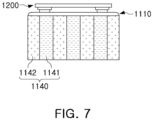
FIGS. 5 to 7 are views illustrating a cell stack assembled into a battery pack according to one embodiment of the present disclosure. -
FIG. 8 is a view illustrating a process of assembling a cell stack according to one embodiment of the present disclosure into a battery pack. -
FIGS. 9 and 10 are diagrams illustrating a battery pack to which a cooling structure according to various embodiments of the present disclosure is applied. -
FIG. 1 is an exploded perspective view of a battery pack according to one embodiment of the present disclosure. - Referring to
FIG. 1 , abattery pack 1000 according to one embodiment of the present disclosure may include apack housing 1010, a plurality of cell stacks (or battery module) 1100 accommodated in thepack housing 1010, and apack cover 1020 coupled to thepack housing 1010 to cover the plurality ofcell stacks 1100. For example, thepack housing 1010 and thepack cover 1020 forming an exterior of thebattery pack 1000 may be formed of a material containing aluminum. - The
pack housing 1010 may form an inner space in which a plurality ofcell stacks 1100 are accommodated. The inner space of thepack housing 1010 may be partitioned into a plurality of spaces so that the plurality ofcell stacks 1100 can be individually disposed. - A
sidewall 1011 may be formed in thepack housing 1010 to penetrate through an inner space, and the inner space may be partitioned or divided into a plurality of spaces by thesidewall 1011. Each of thecell stacks 1100 may be individually disposed in one of the spaces, partitioned by thesidewall 1011. - In one embodiment, referring to the accompanying drawings, the
sidewall 1011 may have a shape extending in a Y-direction, and as thesidewall 1011 is disposed, the inner space may be partitioned in an X-direction. The plurality ofcell stacks 1100 may be disposed in respective spaces, partitioned in the X-direction. - A
pack cover 1020 may be coupled to an upper portion of thepack housing 1010 in a state in which the plurality ofcell stacks 1100 are disposed in the inner space. Thepack cover 1020 may be coupled to thepack housing 1010 to completely cover the inner space. The plurality ofcell stacks 1100 disposed in the inner space may be protected from external impacts by thepack cover 1020. - According to one embodiment of the present disclosure, the plurality of
cell stacks 1100 may include a plurality ofbattery cells 1110 arranged in one direction. In one embodiment, referring to the drawings, the plurality ofcell stacks 1100 may include a plurality ofbattery cells 1110 arranged in a Y-direction. Asupport member 1140 supporting the plurality ofbattery cells 1110 may be disposed outside the plurality ofbattery cells 1110. Thesupport member 1140 may support the plurality ofbattery cells 1110 in the Y-direction in which the plurality ofbattery cells 1110 are arranged. A description related to thesupport member 1140 will be described later. - According to one embodiment of the present disclosure, the plurality of
battery cells 1110 may beprismatic battery cells 1110. That is, thebattery module 1100 may include a plurality ofprismatic battery cells 1110 arranged in a Y-direction. The plurality ofprismatic battery cells 1110 may be arranged in the Y-direction so that wide surfaces thereof face each other. - The prismatic battery cell may refer to a battery cell in which a
case 1111 accommodating an electrode assembly and an electrolyte has a flat and angular shape, and thecase 1111 may be made of aluminum. - According to one embodiment of the present disclosure, the plurality of
prismatic battery cells 1110 may have positive and negative electrode terminals (or electrode terminals) protruding to one side thereof for example in a height direction (e.g., Z-direction). Thepositive electrode terminal 1112 and thenegative electrode terminal 1113 may be provided to be spaced apart from each other in a length direction (e.g., X-direction) of thebattery cell 1110. The plurality ofbattery cells 1110 may be electrically connected to neighboringbattery cells 1110 through an electrode terminal. - In addition, referring to the drawings, a vent portion 1115 (shown in
FIG. 2 ) may be provided in thecase 1111 between thepositive electrode terminal 1112 and thenegative electrode terminal 1113. The vent portion 115 may be a passage through which gas generated inside thecase 1111 is discharged. - According to one embodiment of the present disclosure, a bus bar assembly 1200 (as shown in
FIG. 1 ) may be disposed on an upper side of the plurality ofcell stacks 1100. Thebus bar assembly 1200 may (as shown inFIG. 1 ) include abus bar 1210 electrically connected to an electrode terminal and abus bar frame 1220 on which thebus bar 1210 is disposed. In addition, thebus bar assembly 1200 may include a flexible printed circuit board (FPCB) 1230 (as shown inFIG. 1 ) electrically connected to thebus bar 1210 and receiving a voltage, temperature information, and the like, of the plurality ofbattery cells 1110. - According to one embodiment of the present disclosure, the
bus bar frame 1220 may extend in a longitudinal direction (Y-direction based on the drawing) of thecell stack 1100, and may overlap the plurality ofbattery cells 1110 on an upper side of thebattery module 1100. - Meanwhile, a portion of both sides of the plurality of
battery cells 1110 in the longitudinal direction (X-direction based on the drawing) may not overlap the bus bar frame 1220 (in this case, thepositive electrode terminal 1112 and thenegative electrode terminal 1113 of at least the plurality ofbattery cells 1110 may overlap the bus bar frame 1220), and the corresponding portion may overlap afixing bracket 1300 to be described later. That is, abus bar assembly 1200 and afixing bracket 1300 may be disposed on an upper side of thecell stack 1100 according to one embodiment of the present disclosure. - The
bus bar frame 1220 may include a hole exposingelectrode terminals battery cells 1110 andvent portion 1115, and thebus bar 1210 may be electrically connected to theelectrode terminals - The
bus bar 1210 may electrically connectelectrode terminals battery cells 1110. In the accompanying drawings, a plurality ofbattery cells 1110 as illustrated are connected in series through the bus bar, but this embodiment thereof is not limited thereto, and various connection structures may be employed as needed. - According to one embodiment of the present disclosure, a
fixing bracket 1300 may be disposed on an upper side of the plurality of cell stacks 1100. The fixingbracket 1300 may be a component fixing and coupling thecell stack 1100 to thebattery pack 1000. -
FIG. 2 is a plan view illustrating an assembled state of the battery pack according to one embodiment of the present disclosure, andFIGS. 3 and 4 are side views illustrating an assembled state of the battery pack according to one embodiment of the present disclosure. - The
cell stack 1100 according to one embodiment of the present disclosure may not include a housing or top cover closing the plurality ofbattery cells 1110 except for thesupport member 1140. Accordingly, the plurality ofbattery cells 1110 may be directly fixed and coupled to thepack housing 1010. - The fixing
bracket 1300 may be disposed to simultaneously overlap the plurality ofcell stacks 1100 and the pack housing 1010 (including the side walls 1011). The fixingbracket 1300 may have a length in an X-direction so as to cover thecell stack 1100 and thepack housing 1010 at the same time, and may have a length in a Y-direction so as to overlap the plurality ofbattery cells 1110 included in thecell stack 1100 at the same time. - Both sides of the plurality of
cell stacks 1100 may be supported by the fixingbrackets 1300. Referring toFIGS. 2 and3 , the fixingbracket 1300 may be disposed between thecell stack 1100 and thepack housing 1010 and between the plurality of cell stacks 1100. While the fixingbracket 1300 illustrated inFIGs. 1 and2 comprisesseparate elements elements - The fixing
bracket 1300 may include afirst fixing bracket 1310 and asecond fixing bracket 1320 which, in order to distinguish them from the fixingbracket 1300, may also be referred to as fixing bracket elements (1310, 1320). The first fixing bracket 1310 (first fixing bracket element 1310) may be a fixing bracket (fixing bracket element) disposed between thecell stack 1100 and thepack housing 1010, and the second fixing bracket 1320 (second fixing bracket element 1320) may be a fixing bracket (fixing bracket element) disposed between the plurality of cell stacks 1100. - The fixing
bracket 1300 may include two first fixing brackets 1310 (first fixing bracket elements 1310) and one or more second fixing brackets 1320 (second fixing bracket elements 1320) . Since the first fixing bracket 1310 (first fixing bracket element 1310) is disposed between thecell stack 1100 and thepack housing 1010, two first fixing brackets 1310 (first fixing bracket elements 1310) may be provided. Meanwhile, a different number of second fixing brackets 1320 (second fixing bracket elements 1320) disposed between the plurality ofcell stacks 1100 may be provided according to the number of the plurality of cell stacks 1100. For example, when thebattery pack 1000 includes n cell stacks 1100, n-1 second fixing brackets 1320 (second fixing bracket elements 1320) may be provided. - The first fixing bracket 1310 (first fixing bracket element 1310) and the second fixing bracket 1320 (second fixing bracket element 1320) may include
extension portions cell stack 1100. - In detail, the first fixing bracket 1310 (first fixing bracket element 1310) and the second fixing bracket 1320 (second fixing bracket element 1320) may include
fastening portions pack housing 1010 or theside wall 1011, andextension portions cell stack 1100. - The
fastening portions pack housing 1010 or theside wall 1011 and thecell stack 1100. In addition, thefastening portions holes fastening member 1400 is inserted in a longitudinal direction. - As illustrated in
FIG. 3 , thefastening member 1400 may be fastened to thepack housing 1010 in the z direction. In this case,multiple fastening members 1400 are inserted into the through-holes brackets 1310 and 1320 (fixingbracket elements 1310 and 1320) . - The
side wall 1011 of thepack housing 1010 may include a fastening hole 1012 (shown inFIG. 1 ) in which thefastening member 1400 is accommodated and fastened, and thefastening member 1400 may be fastened to thepack housing 1010 while being inserted into thefastening hole 1012. - The
extension portions fastening portions extension portions battery module 1100, and theextension portions cell stack 1100. The plurality ofcell stacks 1100 may be pressed and fixed in the z direction by theextension portions fastening member 1400 is fastened to thefastening portions - Since the first fixing bracket 1310 (first fixing bracket element 1310) is disposed between the
cell stack 1100 and thepack housing 1010, the first fixing bracket 1310 (first fixing bracket element 1310) may include only oneextension portion 1311. In addition, since the second fixing bracket 1320 (second fixing bracket element 1320) is disposed between the plurality ofcell stacks 1100, the second fixing bracket 1320 (second fixing bracket element 1320) may include twoextension portions 1321. For example, a cross-section of the first fixing bracket 1310 (first fixing bracket element 1310) may be a '┐' or '┌' shape (generally referred to as reversed L-shape), and a cross-section of the second fixing bracket 1320 (second fixing bracket element 1320) may be a '┬' shape (generally referred to as T-shape). - Meanwhile,
FIG. 4 is a view illustrating a state in which thecell stack 1100 is assembled to thepack housing 1010 when viewed from the X-direction. Prior to this description, thecell stack 1100 according to one embodiment of the present disclosure will be described with reference toFIGS. 5 to 7 . -
FIGS. 5 and7 are views illustrating a cells stack assembled into a battery pack according to one embodiment of the present disclosure. - A
cell stack 1100 according to this embodiment of the present disclosure may include a plurality ofprismatic battery cells 1110 arranged in one direction. For example, the plurality ofprismatic battery cells 1110 may be arranged in a Y-direction so that wide surfaces thereof face each other. - The plurality of
battery cells 1110 may be arranged in the Y-direction at a predetermined interval, and acompression member 1150 may be disposed at intervals between each of the plurality ofbattery cells 1110. Thecompression member 1150 may be disposed between the plurality ofbattery cells 1110 to absorb swelling of thebattery cells 1110 and maintain the interval between the plurality ofbattery cells 1110. For example, thecompression member 1150 may be formed of a material such as polyurethane. In addition, as will be described later, thecompression member 1150 may prevent the plurality ofbattery cells 1110 from sagging when thebattery module 1100 is lifted. - The
cell stack 1100 according to one embodiment of the present disclosure may include asupport member 1140 on both sides of an arrangement direction of the plurality ofbattery cells 1110. Thesupport member 1140 may be disposed outside the arrangement direction of the plurality ofbattery cells 1110 to support the plurality ofbattery cells 1110 in the y-direction. Thesupport member 1140 may be fixed to a side surface of thebattery cell 1110, disposed on an outermost side thereof or acompression member 1150, through an adhesive material. Thesupport member 1140 may reduce a swelling phenomenon of the plurality ofbattery cells 1110 according to charging and discharging. - The
support member 1140 may be formed of a plastic material, for example, a material such as polypropylene, and more specifically, may be provided in a form of a plastic injection molding into which die cast aluminum (Al) is inserted to reinforce rigidity. In addition, thesupport member 1140 may include abus bar 1210, in detail, a part to which a HV terminal of the bus bar is connected. - Referring to
FIG. 7 , thesupport member 1140 may include aninsertion groove 1141 on one surface facing thepack housing 1010. Theinsertion groove 1141 may be formed in a height direction (e.g., z direction based on the drawing), and may be provided in plurality in a width direction of thecell stack 1100. Aprotrusion 1142, protruding relatively more than aninsertion groove 1141 may be alternately formed with aninsertion groove 1141 on the one surface of thesupport member 1140, and theinsertion groove 1141 may respectively be formed between theprotrusions 1142.Legs 150 of a device (hereinafter, referred to as a lifting device) for transferring thecell stack 1100 to thepack housing 1010 may be inserted into theinsertion groove 1141. -
FIG. 8 is a view illustrating a process of assembling a cell stack according to one embodiment of the present disclosure into a battery pack. - Referring to
FIG. 8 , acell stack 1100 according to this embodiment of the present disclosure may be transported by alifting device 100 and assembled to apack housing 1010. Specifically, thelifting device 100 may lift thecell stack 1100 in a state in which theleg 150 of thelifting device 100 is inserted into aninsertion groove 1141 of thesupport member 1140 and transfers the same into thepack housing 1010. When thecell stack 1100 is lifted in a state in which theleg 150 of the lifting device is inserted into theinsertion groove 1141, since thebattery module 1100 does not include a separate housing, a sagging phenomenon of the plurality ofbattery cells 1110 in a direction of gravity may occur. Accordingly, as described above, thebattery module 1100 according to one embodiment of the present disclosure may prevent this by including thecompression member 1150 between the plurality ofbattery cells 1110. - According to one embodiment of the present disclosure, as illustrated in
FIG. 4 , thesupport member 1140 may have a shape in which one surface thereof facing thepack housing 1010 is inclined. For example, thesupport member 1140 may have a shape in which the thickness decreases from an upper side to a lower side, and from the viewpoint of thecell stack 1100, may have a shape in which a length of thecell stack 1100 may be reduced. An inner side surface of thepack housing 1010 facing the one surface of thesupport member 1140 may have an inclined shape corresponding thereto. When thesupport member 1140 has such a shape, thecell stack 1100 may be more easily assembled to thepack housing 1010 along the inclined surface of thepack housing 1010. However, this is merely one embodiment of the present disclosure, and thesupport member 1140 may not have an inclined shape. - Meanwhile, according to another embodiment of the present disclosure, a gap filler (such as
gap filler 1510 described below) may be disposed between thepack housing 1010 and thecell stack 1100. The gap filler has a relatively weak adhesive force, so that thecell stack 1100 may be attached or detached, and has an advantage in that thecell stack 1100 may be easily replaced. -
FIGS. 9 and 10 are diagrams illustrating a battery pack to which a cooling structure according to embodiments of the present disclosure is applied. - Referring to
FIGS. 9 and 10 , in abattery pack 1000 according to one embodiment of the present disclosure, a cooling structure (hereinafter referred to as a cooling plate) may be applied to an upper or a lower side of apack housing 1010. In other words, in thebattery pack 1000 according to this embodiment of the present disclosure, a cooling plate does not necessarily need to be disposed at a predetermined location, and may be selectively disposed on an upper side or a lower side of thepack housing 1010. - In one embodiment, the
battery pack 1000 may include acooling plate 1500 between a bottom surface of thepack housing 1010 and acell stack 1100. In this case, thecell stack 1100 may be disposed so that an electrode terminal of the plurality ofbattery cells 1110 face an upper portion of thebattery pack 1000, that is, apack cover 1020. In another embodiment, thebattery pack 1000 may include acooling plate 1500 between thepack cover 1020 and thecell stack 1100. In this case, thecell stack 1100 may be disposed so that an electrode terminal of the plurality ofbattery cells 1110 face a lower portion of thebattery pack 1000, that is, the bottom surface of thepack housing 1010. - Meanwhile, a
gap filler 1510 may be further disposed between thecooling plate 1500 and thecell stack 1100. For example, thegap filler 1510 may be a thermal pad that facilitates thermal transfer. Accordingly, when thegap filler 1510 is provided such as a thermal pad, cooling efficiency may be increased. Alternately, agap filler 1510 may be provided as a thermal interface material (TIM) with non-adhesive for recycling or reusing. - As described above, the
battery pack 1000 according to one embodiment of the present disclosure may not include a separate cover covering a plurality ofbattery cells 1110, excluding asupport member 1140 disposed in a stacking direction of the plurality ofbattery cells 1110 to transfer thecell stack 1100, and may replace a cover of thebattery module 1100 in which thepack housing 1010 is omitted. Accordingly, economic feasibility of manufacturing thebattery pack 1000 may be secured, and sufficient rigidity may be maintained through the thickness of thepack housing 1010, and the like. - As set forth above, according to one embodiment of the present disclosure, a battery pack has an advantage in that productivity is improved, and it is advantageous for reducing weight.
- In addition, the battery pack according to one embodiment of the present disclosure may secure sufficient rigidity even though it has a simplified structure.
Claims (15)
- A battery pack (1000), comprising:a plurality of cell stacks (1100) including a plurality of battery cells (1110);a pack housing (1010) accommodating the plurality of cell stacks (1100);at least one fixing bracket (1300) disposed both between the plurality of cell stacks (1100) and the pack housing (1010) and between two adjacent cell stacks (1100) of the plurality of cell stacks (1100); anda fastening member (1400) fastening the fixing bracket (1300) to the pack housing (1010),wherein the at least one fixing bracket (1300) is disposed to contact the plurality of battery cells (1110) on an upper side of the plurality of cell stacks (1100).
- The battery pack (1000) of claim 1, wherein the at least one fixing bracket (1300) comprisesa first fixing bracket (1310) disposed to overlap one of the plurality of cell stacks (1100); anda second fixing bracket (1320) disposed to overlap the two adjacent cell stacks (1100).
- The battery pack (1000) of claim 2, wherein the first fixing bracket (1310) and the second fixing bracket (1320) have a length of the plurality of battery cells (1110) in a stacking direction, and
each of the first fixing bracket (1310) and the second fixing bracket (1320) comprises a fastening portion (1311, 1321) through which the fastening member (1400) passes and an extension portion (1312, 1322) extending from the fastening portion (1311, 1321) to cover the upper side of the plurality of battery cells(1110). - The battery pack (1000) of claim 3, wherein the extension portion (1312, 1322) of the first fixing bracket (1310) comprises only one extension portion (1312), and the extension portion(1322) of the second fixing bracket (1320) comprises two extension portions (1322).
- The battery pack (1000) of any of claims 1 to 4, wherein the cell stack (1100) further comprises a support member (1140) disposed between the plurality of battery cells and the housing to cover both sides of the plurality of battery cells.
- The battery pack (1000) of claim 5, wherein one surface of the support member (1140), facing the pack housing (1010), comprises a plurality of protrusions (1142) and a plurality of insertion grooves (1141), alternately formed, and the plurality of insertion grooves (1141) are disposed between the plurality of protrusions (1142).
- The battery pack (1000) of claim 5, wherein one surface of the support member (1140), facing the pack housing (1010), is disposed in an inclined shape so that a thickness decreases from an upper side to a lower side of the support member (1140), and the pack housing (1010) is formed in a shape corresponding thereto.
- The battery pack (1000) of any of claims 1 to 7, wherein the plurality of cell stacks (1100) further comprise a compression member (1150) disposed between at least two of the plurality of battery cells (1110).
- The battery pack (1000) of any of claims 1 to 8, wherein the plurality of battery cells (1110) comprising the plurality of cell stacks (1100) are prismatic battery cells including an electrode terminal (1112) on one side of the plurality of battery cells (1110).
- The battery pack (1000) of claim 9, further comprising:a bus bar (1210) a) disposed on a side of one surface of the plurality of battery cells(1110) provided with the electrode terminal (1112) and b) electrically connected to the electrode terminal (1112); anda bus bar assembly (1200) including a bus bar frame (1220) on which the bus bar (1210) is disposed.
- The battery pack (1000) of claim 10, further comprising:
a cooling plate (1500) disposed opposite to the bus bar assembly (1200) and under the plurality of cell stacks (1100). - The battery pack (1000) of any of claims 1 to 11, further comprising:
a pack cover (1020) coupled to the pack housing (1010) and covering the plurality of cell stacks (1100). - A method of assembling a battery pack (1000), comprising:a transfer operation of transferring a plurality of cell stacks (1100) including a plurality of battery cells (1110) stacked in one direction and a support member (1140) disposed to cover the plurality of battery cells (1110) in a stacking direction of the plurality of battery cells (1110) to a pack housing (1010);a disposing operation of disposing at least one fixing bracket (1300) both between the plurality of cell stacks (1100) and the pack housing(1010) and between each of the plurality of cells stacks (1100); anda fixing operation of fixing the plurality of cell stacks (1100) to the pack housing (1010) by fastening a fastening member (1400) to penetrate through the fixing bracket (1300) and fasten to the pack housing (1010),wherein, in the disposing operation, the fixing bracket (1300) is disposed to contact the plurality of battery cells (1110) on an upper side of the plurality of cell stacks (1100).
- The method of assembling a battery pack (1000) of claim 13, wherein the plurality of cell stacks (1100) are transferred to the pack housing(1010) by a lifting device (100), and the support member (1140) comprises a plurality of insertion grooves (1141) into which legs (150) of the lifting device (100) are inserted.
- The method of assembling a battery pack (1000) of claim 13, wherein a compression member (1150) is disposed between at least the plurality of battery cells (1110), and configured to absorb pressure applied in a direction in which the plurality of battery cells (1110) are stacked when the plurality of cell stacks (1100) are transferred.
Applications Claiming Priority (1)
| Application Number | Priority Date | Filing Date | Title |
|---|---|---|---|
| KR1020220159270A KR20240077123A (en) | 2022-11-24 | 2022-11-24 | Battery Pack and method assembling the same |
Publications (2)
| Publication Number | Publication Date |
|---|---|
| EP4376185A1 true EP4376185A1 (en) | 2024-05-29 |
| EP4376185B1 EP4376185B1 (en) | 2026-04-22 |
Family
ID=87556058
Family Applications (1)
| Application Number | Title | Priority Date | Filing Date |
|---|---|---|---|
| EP23189370.2A Active EP4376185B1 (en) | 2022-11-24 | 2023-08-03 | Battery pack and method of assembling the same |
Country Status (4)
| Country | Link |
|---|---|
| US (3) | US12074334B2 (en) |
| EP (1) | EP4376185B1 (en) |
| KR (1) | KR20240077123A (en) |
| CN (1) | CN118073741A (en) |
Citations (5)
| Publication number | Priority date | Publication date | Assignee | Title |
|---|---|---|---|---|
| JP6680145B2 (en) * | 2016-08-24 | 2020-04-15 | トヨタ自動車株式会社 | Battery module |
| JP2021007090A (en) * | 2019-06-27 | 2021-01-21 | 寧徳時代新能源科技股▲分▼有限公司Contemporary Amperex Technology Co., Limited | Battery pack and vehicle |
| CN111490195B (en) * | 2019-01-29 | 2022-05-24 | 奥迪股份公司 | Battery assembly method for providing battery device and battery device |
| CN111033796B (en) * | 2017-09-07 | 2022-11-01 | 松下知识产权经营株式会社 | Battery module |
| CN115347298A (en) * | 2021-05-12 | 2022-11-15 | Sk新能源株式会社 | Battery pack |
Family Cites Families (3)
| Publication number | Priority date | Publication date | Assignee | Title |
|---|---|---|---|---|
| KR101698770B1 (en) | 2012-03-23 | 2017-01-23 | 삼성에스디아이 주식회사 | Battery pack |
| KR20150024724A (en) * | 2013-08-27 | 2015-03-09 | 삼성에스디아이 주식회사 | Battery pack |
| KR102397218B1 (en) | 2015-08-27 | 2022-05-12 | 삼성에스디아이 주식회사 | Battery pack |
-
2022
- 2022-11-24 KR KR1020220159270A patent/KR20240077123A/en active Pending
-
2023
- 2023-08-02 US US18/363,743 patent/US12074334B2/en active Active
- 2023-08-03 EP EP23189370.2A patent/EP4376185B1/en active Active
- 2023-08-07 CN CN202310985576.7A patent/CN118073741A/en active Pending
-
2024
- 2024-07-02 US US18/761,336 patent/US12418067B2/en active Active
- 2024-07-02 US US18/761,327 patent/US12368204B2/en active Active
Patent Citations (5)
| Publication number | Priority date | Publication date | Assignee | Title |
|---|---|---|---|---|
| JP6680145B2 (en) * | 2016-08-24 | 2020-04-15 | トヨタ自動車株式会社 | Battery module |
| CN111033796B (en) * | 2017-09-07 | 2022-11-01 | 松下知识产权经营株式会社 | Battery module |
| CN111490195B (en) * | 2019-01-29 | 2022-05-24 | 奥迪股份公司 | Battery assembly method for providing battery device and battery device |
| JP2021007090A (en) * | 2019-06-27 | 2021-01-21 | 寧徳時代新能源科技股▲分▼有限公司Contemporary Amperex Technology Co., Limited | Battery pack and vehicle |
| CN115347298A (en) * | 2021-05-12 | 2022-11-15 | Sk新能源株式会社 | Battery pack |
Also Published As
| Publication number | Publication date |
|---|---|
| KR20240077123A (en) | 2024-05-31 |
| US12418067B2 (en) | 2025-09-16 |
| EP4376185B1 (en) | 2026-04-22 |
| US20240356129A1 (en) | 2024-10-24 |
| CN118073741A (en) | 2024-05-24 |
| US20240356128A1 (en) | 2024-10-24 |
| US20240178497A1 (en) | 2024-05-30 |
| US12368204B2 (en) | 2025-07-22 |
| US12074334B2 (en) | 2024-08-27 |
Similar Documents
| Publication | Publication Date | Title |
|---|---|---|
| KR101909215B1 (en) | Battery submodule carrier, battery submodule, battery system and vehicle | |
| US10862082B2 (en) | Battery module assembly | |
| US7858229B2 (en) | Cell-module cartridge, cell-module including the cell-module cartridge, and battery module including the cell-module | |
| US9640790B2 (en) | Middle or large-sized battery module | |
| US9203065B2 (en) | Battery module | |
| KR101750487B1 (en) | Battery Module Having Mounting Means of Bus Bar and External Input-Output Terminal | |
| KR20120074425A (en) | Battery module and battery pack employed with the same | |
| EP3723156B1 (en) | Spacer for a battery stack | |
| US12160019B2 (en) | Battery module and battery pack | |
| US12021204B2 (en) | Battery module comprising a top cover coupled to a connection board and battery pack including the same | |
| US20250286201A1 (en) | Electricity storage device | |
| KR20240024622A (en) | Battery module and battery pack including the same | |
| EP4376185B1 (en) | Battery pack and method of assembling the same | |
| US20240429485A1 (en) | Battery pack | |
| US20250070367A1 (en) | Rechargeable battery module | |
| EP4447204A1 (en) | Rechargeable battery module | |
| KR200500332Y1 (en) | Spacer for a battery stack and battery module comprising the battery stack | |
| CN223884513U (en) | Battery pack and device comprising same | |
| CN121586962A (en) | Battery cell assembly and method of manufacturing the same | |
| CN119856332A (en) | Battery pack | |
| CN120283333A (en) | Battery module and battery pack including the same | |
| KR20260061682A (en) | Busbar and battery pack including the same |
Legal Events
| Date | Code | Title | Description |
|---|---|---|---|
| PUAI | Public reference made under article 153(3) epc to a published international application that has entered the european phase |
Free format text: ORIGINAL CODE: 0009012 |
|
| STAA | Information on the status of an ep patent application or granted ep patent |
Free format text: STATUS: THE APPLICATION HAS BEEN PUBLISHED |
|
| AK | Designated contracting states |
Kind code of ref document: A1 Designated state(s): AL AT BE BG CH CY CZ DE DK EE ES FI FR GB GR HR HU IE IS IT LI LT LU LV MC ME MK MT NL NO PL PT RO RS SE SI SK SM TR |
|
| STAA | Information on the status of an ep patent application or granted ep patent |
Free format text: STATUS: REQUEST FOR EXAMINATION WAS MADE |
|
| 17P | Request for examination filed |
Effective date: 20240703 |
|
| RBV | Designated contracting states (corrected) |
Designated state(s): AL AT BE BG CH CY CZ DE DK EE ES FI FR GB GR HR HU IE IS IT LI LT LU LV MC ME MK MT NL NO PL PT RO RS SE SI SK SM TR |
|
| STAA | Information on the status of an ep patent application or granted ep patent |
Free format text: STATUS: EXAMINATION IS IN PROGRESS |
|
| 17Q | First examination report despatched |
Effective date: 20250219 |
|
| GRAP | Despatch of communication of intention to grant a patent |
Free format text: ORIGINAL CODE: EPIDOSNIGR1 |
|
| STAA | Information on the status of an ep patent application or granted ep patent |
Free format text: STATUS: GRANT OF PATENT IS INTENDED |
|
| RIC1 | Information provided on ipc code assigned before grant |
Ipc: H01M 50/204 20210101AFI20251125BHEP Ipc: H01M 50/289 20210101ALI20251125BHEP Ipc: H01M 50/264 20210101ALI20251125BHEP Ipc: H01M 50/209 20210101ALI20251125BHEP |
|
| INTG | Intention to grant announced |
Effective date: 20251210 |
|
| RIN1 | Information on inventor provided before grant (corrected) |
Inventor name: LEE, SEUNG HUN Inventor name: RHEE, SEO ROH |
|
| GRAS | Grant fee paid |
Free format text: ORIGINAL CODE: EPIDOSNIGR3 |
|
| GRAA | (expected) grant |
Free format text: ORIGINAL CODE: 0009210 |
|
| STAA | Information on the status of an ep patent application or granted ep patent |
Free format text: STATUS: THE PATENT HAS BEEN GRANTED |
|
| P01 | Opt-out of the competence of the unified patent court (upc) registered |
Free format text: CASE NUMBER: UPC_APP_0009258_4376185/2026 Effective date: 20260310 |
|
| AK | Designated contracting states |
Kind code of ref document: B1 Designated state(s): AL AT BE BG CH CY CZ DE DK EE ES FI FR GB GR HR HU IE IS IT LI LT LU LV MC ME MK MT NL NO PL PT RO RS SE SI SK SM TR |
|
| REG | Reference to a national code |
Ref country code: CH Ref legal event code: F10 Free format text: ST27 STATUS EVENT CODE: U-0-0-F10-F00 (AS PROVIDED BY THE NATIONAL OFFICE) Effective date: 20260422 Ref country code: GB Ref legal event code: FG4D |
|
| REG | Reference to a national code |
Ref country code: DE Ref legal event code: R096 Ref document number: 602023015591 Country of ref document: DE |