EP4376176A1 - Battery module - Google Patents
Battery module Download PDFInfo
- Publication number
- EP4376176A1 EP4376176A1 EP23193625.3A EP23193625A EP4376176A1 EP 4376176 A1 EP4376176 A1 EP 4376176A1 EP 23193625 A EP23193625 A EP 23193625A EP 4376176 A1 EP4376176 A1 EP 4376176A1
- Authority
- EP
- European Patent Office
- Prior art keywords
- battery module
- thermal
- blocking member
- frame
- blocking
- Prior art date
- Legal status (The legal status is an assumption and is not a legal conclusion. Google has not performed a legal analysis and makes no representation as to the accuracy of the status listed.)
- Pending
Links
Images





Classifications
-
- H—ELECTRICITY
- H01—ELECTRIC ELEMENTS
- H01M—PROCESSES OR MEANS, e.g. BATTERIES, FOR THE DIRECT CONVERSION OF CHEMICAL ENERGY INTO ELECTRICAL ENERGY
- H01M10/00—Secondary cells; Manufacture thereof
- H01M10/60—Heating or cooling; Temperature control
- H01M10/65—Means for temperature control structurally associated with the cells
- H01M10/658—Means for temperature control structurally associated with the cells by thermal insulation or shielding
-
- H—ELECTRICITY
- H01—ELECTRIC ELEMENTS
- H01M—PROCESSES OR MEANS, e.g. BATTERIES, FOR THE DIRECT CONVERSION OF CHEMICAL ENERGY INTO ELECTRICAL ENERGY
- H01M10/00—Secondary cells; Manufacture thereof
- H01M10/60—Heating or cooling; Temperature control
- H01M10/64—Heating or cooling; Temperature control characterised by the shape of the cells
- H01M10/647—Prismatic or flat cells, e.g. pouch cells
-
- H—ELECTRICITY
- H01—ELECTRIC ELEMENTS
- H01M—PROCESSES OR MEANS, e.g. BATTERIES, FOR THE DIRECT CONVERSION OF CHEMICAL ENERGY INTO ELECTRICAL ENERGY
- H01M50/00—Constructional details or processes of manufacture of the non-active parts of electrochemical cells other than fuel cells, e.g. hybrid cells
- H01M50/20—Mountings; Secondary casings or frames; Racks, modules or packs; Suspension devices; Shock absorbers; Transport or carrying devices; Holders
- H01M50/204—Racks, modules or packs for multiple batteries or multiple cells
-
- H—ELECTRICITY
- H01—ELECTRIC ELEMENTS
- H01M—PROCESSES OR MEANS, e.g. BATTERIES, FOR THE DIRECT CONVERSION OF CHEMICAL ENERGY INTO ELECTRICAL ENERGY
- H01M50/00—Constructional details or processes of manufacture of the non-active parts of electrochemical cells other than fuel cells, e.g. hybrid cells
- H01M50/20—Mountings; Secondary casings or frames; Racks, modules or packs; Suspension devices; Shock absorbers; Transport or carrying devices; Holders
- H01M50/204—Racks, modules or packs for multiple batteries or multiple cells
- H01M50/207—Racks, modules or packs for multiple batteries or multiple cells characterised by their shape
- H01M50/211—Racks, modules or packs for multiple batteries or multiple cells characterised by their shape adapted for pouch cells
-
- H—ELECTRICITY
- H01—ELECTRIC ELEMENTS
- H01M—PROCESSES OR MEANS, e.g. BATTERIES, FOR THE DIRECT CONVERSION OF CHEMICAL ENERGY INTO ELECTRICAL ENERGY
- H01M50/00—Constructional details or processes of manufacture of the non-active parts of electrochemical cells other than fuel cells, e.g. hybrid cells
- H01M50/20—Mountings; Secondary casings or frames; Racks, modules or packs; Suspension devices; Shock absorbers; Transport or carrying devices; Holders
- H01M50/244—Secondary casings; Racks; Suspension devices; Carrying devices; Holders characterised by their mounting method
-
- H—ELECTRICITY
- H01—ELECTRIC ELEMENTS
- H01M—PROCESSES OR MEANS, e.g. BATTERIES, FOR THE DIRECT CONVERSION OF CHEMICAL ENERGY INTO ELECTRICAL ENERGY
- H01M50/00—Constructional details or processes of manufacture of the non-active parts of electrochemical cells other than fuel cells, e.g. hybrid cells
- H01M50/20—Mountings; Secondary casings or frames; Racks, modules or packs; Suspension devices; Shock absorbers; Transport or carrying devices; Holders
- H01M50/289—Mountings; Secondary casings or frames; Racks, modules or packs; Suspension devices; Shock absorbers; Transport or carrying devices; Holders characterised by spacing elements or positioning means within frames, racks or packs
- H01M50/293—Mountings; Secondary casings or frames; Racks, modules or packs; Suspension devices; Shock absorbers; Transport or carrying devices; Holders characterised by spacing elements or positioning means within frames, racks or packs characterised by the material
-
- H—ELECTRICITY
- H01—ELECTRIC ELEMENTS
- H01M—PROCESSES OR MEANS, e.g. BATTERIES, FOR THE DIRECT CONVERSION OF CHEMICAL ENERGY INTO ELECTRICAL ENERGY
- H01M50/00—Constructional details or processes of manufacture of the non-active parts of electrochemical cells other than fuel cells, e.g. hybrid cells
- H01M50/30—Arrangements for facilitating escape of gases
- H01M50/35—Gas exhaust passages comprising elongated, tortuous or labyrinth-shaped exhaust passages
- H01M50/358—External gas exhaust passages located on the battery cover or case
-
- H—ELECTRICITY
- H01—ELECTRIC ELEMENTS
- H01M—PROCESSES OR MEANS, e.g. BATTERIES, FOR THE DIRECT CONVERSION OF CHEMICAL ENERGY INTO ELECTRICAL ENERGY
- H01M50/00—Constructional details or processes of manufacture of the non-active parts of electrochemical cells other than fuel cells, e.g. hybrid cells
- H01M50/30—Arrangements for facilitating escape of gases
- H01M50/35—Gas exhaust passages comprising elongated, tortuous or labyrinth-shaped exhaust passages
- H01M50/367—Internal gas exhaust passages forming part of the battery cover or case; Double cover vent systems
-
- H—ELECTRICITY
- H01—ELECTRIC ELEMENTS
- H01M—PROCESSES OR MEANS, e.g. BATTERIES, FOR THE DIRECT CONVERSION OF CHEMICAL ENERGY INTO ELECTRICAL ENERGY
- H01M50/00—Constructional details or processes of manufacture of the non-active parts of electrochemical cells other than fuel cells, e.g. hybrid cells
- H01M50/30—Arrangements for facilitating escape of gases
- H01M50/383—Flame arresting or ignition-preventing means
-
- H—ELECTRICITY
- H01—ELECTRIC ELEMENTS
- H01M—PROCESSES OR MEANS, e.g. BATTERIES, FOR THE DIRECT CONVERSION OF CHEMICAL ENERGY INTO ELECTRICAL ENERGY
- H01M50/00—Constructional details or processes of manufacture of the non-active parts of electrochemical cells other than fuel cells, e.g. hybrid cells
- H01M50/50—Current conducting connections for cells or batteries
- H01M50/502—Interconnectors for connecting terminals of adjacent batteries; Interconnectors for connecting cells outside a battery casing
- H01M50/503—Interconnectors for connecting terminals of adjacent batteries; Interconnectors for connecting cells outside a battery casing characterised by the shape of the interconnectors
-
- H—ELECTRICITY
- H01—ELECTRIC ELEMENTS
- H01M—PROCESSES OR MEANS, e.g. BATTERIES, FOR THE DIRECT CONVERSION OF CHEMICAL ENERGY INTO ELECTRICAL ENERGY
- H01M50/00—Constructional details or processes of manufacture of the non-active parts of electrochemical cells other than fuel cells, e.g. hybrid cells
- H01M50/50—Current conducting connections for cells or batteries
- H01M50/502—Interconnectors for connecting terminals of adjacent batteries; Interconnectors for connecting cells outside a battery casing
- H01M50/507—Interconnectors for connecting terminals of adjacent batteries; Interconnectors for connecting cells outside a battery casing comprising an arrangement of two or more busbars within a container structure, e.g. busbar modules
-
- H—ELECTRICITY
- H01—ELECTRIC ELEMENTS
- H01M—PROCESSES OR MEANS, e.g. BATTERIES, FOR THE DIRECT CONVERSION OF CHEMICAL ENERGY INTO ELECTRICAL ENERGY
- H01M50/00—Constructional details or processes of manufacture of the non-active parts of electrochemical cells other than fuel cells, e.g. hybrid cells
- H01M50/50—Current conducting connections for cells or batteries
- H01M50/572—Means for preventing undesired use or discharge
- H01M50/584—Means for preventing undesired use or discharge for preventing incorrect connections inside or outside the batteries
-
- H—ELECTRICITY
- H01—ELECTRIC ELEMENTS
- H01M—PROCESSES OR MEANS, e.g. BATTERIES, FOR THE DIRECT CONVERSION OF CHEMICAL ENERGY INTO ELECTRICAL ENERGY
- H01M50/00—Constructional details or processes of manufacture of the non-active parts of electrochemical cells other than fuel cells, e.g. hybrid cells
- H01M50/50—Current conducting connections for cells or batteries
- H01M50/572—Means for preventing undesired use or discharge
- H01M50/584—Means for preventing undesired use or discharge for preventing incorrect connections inside or outside the batteries
- H01M50/59—Means for preventing undesired use or discharge for preventing incorrect connections inside or outside the batteries characterised by the protection means
- H01M50/593—Spacers; Insulating plates
-
- Y—GENERAL TAGGING OF NEW TECHNOLOGICAL DEVELOPMENTS; GENERAL TAGGING OF CROSS-SECTIONAL TECHNOLOGIES SPANNING OVER SEVERAL SECTIONS OF THE IPC; TECHNICAL SUBJECTS COVERED BY FORMER USPC CROSS-REFERENCE ART COLLECTIONS [XRACs] AND DIGESTS
- Y02—TECHNOLOGIES OR APPLICATIONS FOR MITIGATION OR ADAPTATION AGAINST CLIMATE CHANGE
- Y02E—REDUCTION OF GREENHOUSE GAS [GHG] EMISSIONS, RELATED TO ENERGY GENERATION, TRANSMISSION OR DISTRIBUTION
- Y02E60/00—Enabling technologies; Technologies with a potential or indirect contribution to GHG emissions mitigation
- Y02E60/10—Energy storage using batteries
Definitions
- Secondary batteries may be recharged and discharged repeatedly, and thus may be used in various devices and systems for supplying electrical power, such as digital cameras, mobile phones, laptop computers, hybrid vehicles, and electric vehicles.
- Examples of the secondary batteries include nickel-cadmium batteries, nickel-metal hydride batteries, nickel-hydrogen batteries, and lithium secondary batteries.
- the disclosed technology may be implemented in some embodiments to provide a battery module capable of inducing a high-temperature gas or flames occurring in a battery cell to flow along a preset path.
- the disclosed technology may also be implemented in some embodiments to provide a battery module capable of blocking heat propagation between neighboring battery cells and preventing a high-temperature gas or flames from flowing in the vicinity of a cell stack.
- a battery module includes: a housing having an internal space; a cell stack accommodated in the internal space, in which a plurality of battery cells and a plurality of thermal blocking members are stacked in a first direction; a plurality of busbars electrically connected to the plurality of battery cells; and a busbar frame supporting the plurality of busbars, wherein the plurality of battery cells respectively include an electrode assembly and an electrode accommodating portion accommodating the electrode assembly, at least one of the plurality of thermal blocking members includes: a body portion disposed to face the electrode accommodating portion and configured to block heat propagation between the plurality of battery cells; and a blocking portion extending from the body portion in a second direction, perpendicular to the first direction, and configured to at least partially block gas flow in the first direction.
- An end portion of the blocking portion may be adjacent to the busbar frame.
- a material of the plurality of thermal blocking members may include at least one of mica, ceramic wool, or aerogel.
- the blocking portion may include: a first blocking portion formed on one side of the body portion and having at least a portion inserted into the busbar frame; and a second blocking portion formed on the other side, opposite to the one side of the body portion.
- At least a portion of the first blocking portion may be disposed between the plurality of busbars.
- the first blocking portion may include: a first end portion facing an inner surface of the busbar frame in the second direction; and a second end portion protruding further in the second direction than the plurality of busbars.
- the busbar frame may include an insertion recess into which the second end portion of the blocking portion is inserted.
- the first blocking portion further may include a step portion connecting the first end portion to the second end portion.
- the housing may include an upper case portion and a lower case portion configured to cover upper and lower portions of the cell stack, respectively, and the upper case portion may include a venting hole configured to allow gas to be discharged therethrough.
- a venting flow path may be formed in a space between the first end portion and the upper case portion.
- the busbar frame may include: a first busbar frame disposed on one side of the cell stack; a second busbar frame disposed on the other side opposite to the one side of the cell stack; and a connection frame connecting the first busbar frame to the second busbar frame.
- the plurality of thermal blocking members may include: a first thermal blocking member in which the first blocking portion is inserted into the first busbar frame; and a second thermal blocking member in which the first blocking portion is inserted into the second busbar frame.
- the first thermal blocking member and the second thermal blocking member may be alternately disposed in the first direction.
- An end portion of the second blocking portion of the first thermal blocking member may be adjacent to the second busbar frame.
- the battery module may further include: a third thermal blocking member disposed between the busbar frame and the first end portion and extending in the first direction.
- the battery module may further include: a fourth thermal blocking member facing the cell stack in a third direction perpendicular to both the first and second directions.
- the third thermal blocking member and the fourth thermal blocking member may be integrally formed.
- secondary batteries may be overheated and, in some instances, may become an ignition source, among others, for example, (1) a battery cell reaches the end of life, (2) a swelling phenomenon occurs in the battery cell due to decomposition battery materials including gases generated from such decomposition, (3) the battery cell is overcharged, (4) the battery cell is exposed to heat, (5) battery structure damages, e.g., when a sharp object, such as a nail, penetrates an outer casing material of the battery cell, or (6) an external impact is applied to the battery cell, the battery cell may cause ignition. Flames or a high-temperature gas spouted from the battery cell may cause a chain ignition of other adjacent battery cells accommodated in the battery device and may cause thermal runaway.
- the disclosed technology can be implemented in some embodiments to provide a discharge structure that can discharge flames or high-temperature gases spouted from the battery cell that otherwise would have affected other battery cells.
- the disclosed technology can be implemented in some embodiments to provide a structure that can block the flow of flames or high-temperature gases inside the battery module and/or induce them to flow in a safe path.
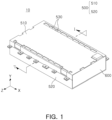
- FIG. 1 is a perspective view of the battery module 10 implemented based on some embodiments of the disclosed technology.
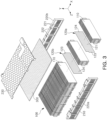
- FIG. 2 is an exploded perspective view of the battery module 10 implemented based on some embodiments of the disclosed technology.
- the battery module 10 may include a housing 500 having an internal space, a plurality of battery cells 110 accommodated in the internal space, a busbar assembly 200 electrically connected to the battery cells 110, and an end cover 600 coupled to at least one side of the housing 500.
- the plurality of battery cells 110 accommodated in the battery module 10 may be stacked in one direction (e.g., an X-axis direction of FIG. 2 ) to form at least a portion of the cell stack 100.
- a stacking direction of the battery cells 110 in which the battery cells 110 are stacked can be referred to as a first direction or a cell stacking direction.
- Each battery cell 110 included in the cell stack 100 may output or store electrical energy.
- the plurality of battery cells 110 may be electrically connected to each other through the busbar assembly 200.
- At least a portion of the busbar assembly 200 may be disposed to face the cell stack 100 in a direction perpendicular to the cell stacking direction.
- the busbar assembly 200 may include a plurality of electrical conductors or electrically conductive members 210 (referred to as busbars 210) for electrically connecting one battery cell 110 to another battery cell 110 and a busbar frame 220 supporting the plurality of busbars 210.
- the busbar 210 may be formed of an electrically conductive material (e.g., a metal) and may serve to electrically connect the plurality of battery cells 110 to each other.
- the busbar 210 may be electrically connected to a lead tab 113 of the battery cell 110.
- the busbar 210 may be bonded to the lead tab 113 of the battery cell 110.
- Various welding methods including laser welding may be applied to the connection between the busbar 210 and the lead tab (e.g., 113 of FIG. 4 ).
- the connection method is not limited to welding, and any connection method capable of electrically conducting two metallic materials may be used.
- the busbar 210 may face the cell stack in a direction (e.g., a Z-axis direction) perpendicular to the first direction (an X-axis direction).
- a direction in which the busbar and the cell stack face each other can be defined as a second direction.
- a direction perpendicular to both the first direction and the second direction is defined as a third direction.
- the third direction may be a height direction of the battery module and may be a direction in which an upper case portion and a lower case portion face each other.
- the busbar assembly 200 may include a terminal portion electrically connected to an external circuit of the battery module 10.
- the terminal portion may be exposed to the outside of the battery module 10 through an opening 540 of the housing 500.
- the busbar frame 220 may structurally support the busbar 210 and may maintain the stability of the busbar 210 even when there is an external shock or vibration.
- the busbar frame 220 may include a plastic material that is lightweight and has excellent mechanical strength, such as polypropylene, polybutylene terephthalate, and modified polyphenylene oxide (MPPO). Therefore, the busbar frame 220 may structurally support the busbar 210, while securing insulation.
- MPPO modified polyphenylene oxide
- the busbar 210 may be fixed to the busbar frame 220 in various manners.
- the busbar 210 may be fixed to the busbar frame 220 by a heat welding process or an insert injection process.
- the busbar assembly 200 may further include a connection frame 230 disposed between the cell stack 100 and the housing 500 and connected to the busbar frame 220.
- the busbar assembly 200 may include a pair of busbar frames 220 facing each other in the second direction with a cell stack interposed therebetween and a connection frame 230 connected to the pair of busbar frames 220 and facing the cell stack in the third direction.
- a sensing module capable of sensing a state of the cell stack 100 may be disposed in the connection frame 230.
- the sensing module may include at least one of a temperature sensor or a voltage sensor.
- the sensing module may sense or detect a state of the battery cell 110 and output sensed information to the outside of the battery module 10.
- the housing 500 provides an internal space in which one or more cell stacks 100 may be accommodated.
- the housing 500 may be formed of a material having predetermined rigidity to protect the cell stack 100 and other electrical components accommodated in the internal space from external impact.
- the housing 500 may include a metal material, such as aluminum.
- the housing 500 may include a lower case portion 520 and an upper case portion 510 coupled to each other.
- a structure of the housing 500 is not limited thereto, and may have any shape as long as the structure has an internal space in which at least one cell stack 100 may be accommodated.
- the housing 500 may be configured as an integral monoframe in which the upper case portion 510 and the lower case portion 520 are integrally formed and both sides are open.
- the housing 500 may include a venting hole 530 through which a gas generated by the cell stack 100 is discharged.
- the venting hole 530 may have a shape of a hole passing through the lower case portion 520 or the upper case portion 510.
- a shielding member may be disposed in the venting hole 530.
- the shielding member may be formed of a thin film or sheet or material layer, and may block foreign matter from being introduced from the outside of the battery module 10.
- the shielding member may include a material that is lightweight and has excellent impact resistance, heat resistance, or electrical insulation.
- the shielding member may include a polycarbonate sheet or layer. In the case of thermal runaway of the battery module 10, at least a portion of the shielding member may be torn so that a gas emitted from the cell stack 100 may pass therethrough properly.
- the end cover 600 may be coupled to one open side of the housing 500.
- the end cover 600 may be provided as a pair and the pair of end covers 600 may be coupled to both open sides of the housing 500, respectively.
- the battery module 10 may include an insulating cover 400.
- the insulating cover 400 may be disposed to face the busbar assembly 200 between the busbar assembly 200 and the housing 500.
- the insulating cover 400 may include an insulating material, and thus may prevent electrical connection between the busbar assembly 200 and the housing 500.
- the insulating cover 400 may be formed of a plastic injection molding material including polypropylene or modified polyphenylene oxide (MPPO).
- MPPO polypropylene or modified polyphenylene oxide
- a material of the insulating cover 400 is not limited thereto.
- the insulating cover 400 may be used to prevent an electrical short circuit from occurring between the cell stack 100 and the housing 500 or between the busbar 210 and the housing 500.
- a heat dissipation member (not shown) may be disposed between the cell stack 100 and the housing 500.
- the heat dissipation member may be disposed such that one surface thereof is in contact with the cell stack 100 and the other surface opposite to the one surface is in contact with the housing 500.
- the heat dissipation member may be provided as a thermal adhesive.
- the heat dissipation member may fill a space between the cell stack 100 and the housing 500 so that heat transfer by conduction may be more actively performed. Accordingly, heat dissipation efficiency of the battery module 10 may be increased.
- the battery module 10 may include a plurality of thermal blocking members 120.
- the cell stack 100 may include the thermal blocking member 120 disposed between the battery cells 110.
- Each thermal blocking member 120 may include one or more thermal insulating materials with low thermal conductivity to provide the thermal blocking function, such as preventing or significantly reduce the undesired heat propagation between neighboring battery cells 110.
- the thermal blocking member 120 may serve to protect the battery cell 110 from physical and thermal shock.
- the thermal blocking member 120 may be configured to block heat propagation from one battery cell 110 to another battery cell 110, while absorbing expansion pressure of the battery cell 110.
- a thermal blocking member 120 may include mica, silicate, graphite, alumina, ceramic wool, super wool, or aerogel.
- the battery module 10 may further include an upper thermal blocking member 300 facing at least one side of the cell stack 100.
- the upper thermal blocking member 300 may be disposed to face the cell stack 100 between the cell stack 100 and the upper case portion 510.
- the upper thermal blocking member 300 may cover an upper side of the cell stack 100 to prevent an occurrence of an unexpected heat propagation path between the cell stack 100 and the housing 500.
- the plurality of thermal blocking members 120 and the upper thermal blocking member 300 may provide a path for gas or flames around the cell stack 100 to move in a preset direction in a thermal runaway situation.
- the thermal blocking member 120 disposed between the battery cells 110 may guide gas or flames toward the top of the battery module 10.
- thermal blocking member 120 included in the battery module 10 characteristics of the thermal blocking member 120 included in the battery module 10 will be described in detail with reference to FIGS. 3 to 6 .
- FIG. 3 illustrates an arrangement of the battery cell 110, the thermal blocking member 120 (e.g., 120a, 120b), and the busbar assembly 200 by way of example.
- FIG. 4 is a perspective view of the battery cell 110 included in the cell stack 100 based on some embodiments of the disclosed technology.
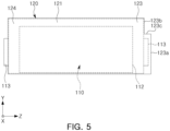
- FIG. 5 is a diagram illustrating the arrangement of the thermal blocking member 120 and the battery cell 110 based on some embodiments of the disclosed technology.
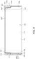
- FIG. 6 is a diagram illustrating formation of a venting flow path VP by the thermal blocking member 120 based on some embodiments of the disclosed technology.
- FIG. 7 is a cross-sectional view taken along line I-I' of FIG. 1 .
- the thermal blocking member 120 and the battery module 10 including the thermal blocking member 120 may be implemented as will be discussed below with reference to FIGS. 3 to 7 .
- the thermal blocking member 120 and the battery module 10 including the thermal blocking member 120 illustrated in FIGS. 3 to 7 may correspond to the thermal blocking member 120 and the battery module 10 including the thermal blocking member 120 illustrated in FIGS. 1 to 2 .
- the cell stack 100 may include a plurality of battery cells 110 and a plurality of thermal blocking members 120 stacked in the first direction (the X-axis direction).
- the battery cell 110 may be configured to convert chemical energy into electrical energy to supply power to an external circuit or receive power from the outside, change electrical energy into chemical energy to store electricity.
- the battery cell 110 may be configured as a nickel metal hydride (Ni-MH) battery or a lithium ion (Li-ion) battery capable of charging and discharging, but is not limited thereto.
- a plurality of battery cells 110 may be electrically connected to each other while being stacked side by side.
- the battery cell 110 may be a pouch-type secondary battery that includes an electrode assembly 114 accommodated in a pouch 111.
- the electrode assembly 114 and an electrolyte may be accommodated in the pouch 111 formed by forming one sheet or material layer or a plurality of outer casing materials.
- the pouch 111 may be formed with one or two receiving portions in a sheet or layer of outer casing material and then folding the outer casing material to form a single space by the receiving portions.
- the pouch 111 may include an electrode accommodating portion 112 accommodating the electrode assembly 114 and an electrolyte (not shown), a sealing portion 115 formed in the periphery of the electrode accommodating portion 112, and a lead tab 113 electrically connected to the electrode assembly 114 and exposed to the outside of the pouch 111.
- the electrode accommodating portion 112 provides an internal space in which the electrode assembly 114 and an electrolyte (not shown) are accommodated.
- the electrode assembly 114 may include a plurality of positive electrode plates and a plurality of negative electrode plates stacked with a separator interposed therebetween.
- a sealing portion 115 formed by bonding the pouch 111 may be disposed along at least a portion of the circumference of the electrode accommodating portion 112.
- a thermal fusion method may be used to bond the pouch 111, but is not limited thereto.
- the sealing portion 115 may include a first sealing portion 115a formed in a portion in which the lead tab 113 is disposed and a second sealing portion 115b formed in a portion in which the lead tab 113 is not disposed.
- the sealing portion 115 may be folded at least once as shown in the partially enlarged view of FIG. 4 .
- the sealing portion 115 may be formed only on three external surfaces of the electrode accommodating portion 112, and a folding portion 118 may be formed on any one external surface of the electrode accommodating portion 112.
- the structure of the battery cell 110 is not limited to the above.
- the electrode accommodating portion 112 may be formed by overlapping two sheets of outer casing materials, and sealing portions may be formed on all four surfaces around the electrode accommodating portion 112.
- the battery cell applied to the battery module based on some example embodiments are not limited to the pouch-type secondary battery described above.
- the battery cell may be configured as a prismatic can-type secondary battery, or a plurality of pouch-type secondary batteries may be grouped and formed as a bundle.
- the cell stack 100 may further include a plurality of thermal blocking members 120 facing the plurality of battery cells 110 in the first direction.
- the plurality of thermal blocking members 120 may be arranged side by side at predetermined intervals in a cell stacking direction (e.g., the X-axis direction of FIG. 3 ).
- One or more battery cells 110 may be disposed between two adjacent thermal blocking members 120. In the drawing, four battery cells 110 are stacked between two thermal blocking members 120, but this is only an example, and three or less or five or more battery cells 110 may be disposed between two thermal blocking members 120.
- the thermal blocking member 120 may block heat and/or flame propagation between adjacent battery cells 110.
- the thermal blocking member 120 may include a material having at least one of flame retardancy, heat resistance, heat insulation, or insulating properties.
- heat resistance may refer to properties that do not melt and do not change in shape even at a temperature of 300°C or higher
- heat insulation may refer to properties that have a thermal conductivity of 1.0 W/mK or less.
- the thermal blocking member 120 may include at least one of mica, silicate, graphite, alumina, ceramic wool, super wool, or aerogel.
- a material of the thermal blocking member 120 is not limited to the materials described above, and any material may be used as long as it can maintain its shape in a thermal runaway situation of the battery cell 110 and prevent propagation of heat or flames to other adjacent battery cells 110.
- a thickness of the thermal blocking member 120 may be less than a thickness of one battery cell 110.
- the thickness may refer to a length in the cell stacking direction.
- the thermal blocking member 120 may include a combination of members having different properties.
- the thermal blocking member 120 may be configured by combining a material for thermal blocking as described above and a material having a predetermined elastic force.
- the thermal blocking member 120 may further include at least one of polyurethane, silicone, or rubber (EPDM), and may press the battery cell 110 using elasticity of these materials.
- EPDM polyurethane, silicone, or rubber
- the thermal blocking member 120 may include a body portion 121 facing the electrode accommodating portion 112 of the battery cell 110 and blocking portions 123 and 124 extending in the second direction (the Z-axis direction) from both ends of the body portion 121.
- FIG. 5 is a view illustrating the thermal blocking member 120 and the battery cell 110 in a stacked state viewed in the cell stacking direction (the X-axis direction).
- the body portion 121 of the thermal blocking member 120 faces the electrode accommodating portion 112 in the first direction (the X-axis direction), and may block heat propagation between neighboring battery cells 110.
- the blocking portions 123 and 124 of the thermal blocking member 120 may refer to portions extending in the second direction (the Z-axis direction) from both ends of the body portion 121. As the blocking portions 123 and 124 are formed, a length of the thermal blocking member 120 in the second direction (the Z-axis direction) based on some example embodiments may be longer than a length of the electrode accommodating portion 112 in the second direction (the Z-axis direction). For example, the blocking portions 123 and 124 may extend from the end portion of the body portion 121 in the second direction (the Z-axis direction) so that end portions thereof are adjacent to the busbar frame 220.
- the blocking portions 123 and 124 may include a first blocking portion 123 at least partially inserted into the busbar frame 220 and a second blocking portion 124 provided on the opposite side of the first blocking portion 123 based on the body portion 121.
- a portion of the first blocking portion 123 may be inserted into the busbar frame 220 and protrude further in the second direction (the Z-axis direction) than the busbar 210.
- the first blocking portion 123 may have a first end portion 123b facing an inner surface of the busbar frame 220 in the second direction (the Z-axis direction) and a second end portion 123a further protruding in the second direction (the Z-axis direction) than the first end portion and inserted into the busbar frame 220. Due to a positional difference between the first end portion 123b and the second end portion 123a, a step portion 123c may be formed between the first end portion 123b and the second end portion 123a.
- the second end portion 123a of the first blocking portion 123 may be inserted into the busbar frame 220.
- An insertion groove 222 into which the second end portion 123a is inserted may be disposed in the busbar frame 220.
- a slit opening 221 into which the lead tab 113 of the battery cell 110 is inserted may be disposed in the busbar frame 220.
- the second end portion 123a of the first blocking portion 123 may protrude further in the second direction (the Z-axis direction) than the busbar 210. That is, a distance between a side surface of the housing 500 and the second end portion 123a in the second direction (the Z-axis direction) may be less than a distance between the side surface of the housing 500 and the busbar 210 in the second direction (the Z-axis direction).
- a region having the second end portion 123a in the first blocking portion 123 may be inserted into the busbar frame 220 and disposed between two adjacent busbars 210. Accordingly, the first blocking portion 123 may prevent physical contact between the two busbars 210.
- the second end portion 123a of the first blocking portion 123 is configured to protrude further in the second direction (the Z-axis direction) than the busbar 210, the occurrence of an unexpected short circuit between the busbars 210 in a thermal runaway situation may be physically prevented.
- the second blocking portion 124 may be formed on the other side opposite to one side of the body portion 121. Unlike the first blocking portion 123, the second blocking portion 124 may not have a portion inserted into the busbar frame 220. However, in some implementations, a portion of the second blocking portion 124 may be inserted into the busbar frame 220.
- An end portion of the second blocking portion 124 may be disposed to face an inner surface of the busbar frame 220 so as not to interfere with the busbar 210.
- the first blocking portion 123 of one of the thermal blocking members 120 is inserted into the first busbar frame 220, and the first blocking portion 123 of the other of the thermal blocking members 120 may be inserted into the second busbar frame 220.
- the first busbar frame 220 For example, referring to FIG.
- a pair of busbar frames 220 may include a first busbar frame 220a and a second busbar frame 220b spaced apart from each other in the second direction (the Z-axis direction), and the plurality of thermal blocking members 120 may include a first thermal blocking member 120a in which the first blocking portion 123 is inserted into the first busbar frame 220a and a second thermal blocking member 120b in which the first blocking portion 123 is inserted into the second busbar frame 220b.
- the first thermal blocking member 120a and the second thermal blocking member 120b may be alternately disposed in the first direction (the X-axis direction).
- the first blocking portion 123 and the second blocking portion 124 may serve to block gas or flames occurring in a thermal runaway situation from flowing in the first direction (the X-axis direction) in the vicinity of the cell stack. Since the flow of gas or flames in the first direction (the X-axis direction) is blocked by the first blocking portion 123 and the second blocking portion 124, the gas or flames may be naturally guided to flow in a direction (for example, a third direction (a Y-axis direction) in which the upper case portion and the lower case portion face each other) perpendicular to the first direction (the X-axis direction).
- a direction for example, a third direction (a Y-axis direction) in which the upper case portion and the lower case portion face each other
- the battery module 10 based on some example embodiments includes the thermal blocking member 120 having the blocking portions 123 and 124, so that undesirable flow of high-temperature gas or flames in the vicinity of the cell stack 100 may be suppressed in a thermal runaway situation.
- the thermal blocking member 120 based on some example embodiments extends in length to the busbar frame 220 to block undesirable flow of high-temperature gas or flames between the busbar frame 220 and the cell stack 100 and guide a flow path thereof in a certain direction.
- FIGS. 6 and 7 illustrate a flow path of gas and/or flames described above.
- the venting flow path VP through which gas or flames flow may have a specific position or path that is determined by the blocking portions 123 and 124 of the thermal blocking member 120.
- the blocking portions 123 and 124 of the thermal blocking member 120 have properties, such as flame retardancy, heat resistance, and heat insulation, the blocking portions 123 and 124 may maintain shapes thereof even in high-temperature environments. In a thermal runaway situation, gas or flames occurring in the cell stack 100 may be blocked by the blocking portions 123 and 124 of the thermal blocking member 120 and flow along surfaces of the blocking portions 123 and 124.
- the venting flow path VP may be formed to connect to the outside the busbar frame 220 by the blocking portions 123 and 124. Therefore, as shown in FIG. 7 , some of the venting flow paths VP may be formed in a space between the external surface of the busbar frame 220 and the housing 500.
- the venting flow path VP formed inside the busbar frame 220 may be blocked in a flow in the first direction (the X-axis direction) by the blocking portions 123 and 124 and may be formed in a direction (the Y-axis direction) toward an upper side of the battery module 10. That is, the blocking portions 123 and 124 extending in the second direction (the Z-axis direction) from the body portion 121 blocks the flow of gas or flames in the first direction (the X-axis direction) perpendicular to the second direction (the Z-axis direction) and allows gas or flames to flow in the third direction (the Y-axis direction).
- the thermal blocking member 120 may guide a flow of gas or flames toward the upper side of the battery module 10.
- the thermal blocking member 120 may prevent gas or flames from spreading in the cell stacking direction in the vicinity of the cell stack 100, thereby preventing the battery cells 110 from being sequentially ignited by gas or flames.
- the busbar frame 220 may be formed of a material relatively vulnerable to high temperatures than the thermal blocking member 120.
- the busbar frame 220 may be structurally collapsed by high-temperature gas or flames occurring in a thermal runaway situation. In this case, there is a risk that gas or flames may spread through an empty space formed as the busbar frame 220 collapses. In this situation, the thermal blocking member 120 may guide a flow path of gas or flames to a safe path.
- the inset on the left in FIG. 6 illustrates an example of the busbar frame 220 before a thermal runaway situation occurs
- the inset on the right in FIG. 6 illustrates an example of the busbar frame 220 that has been melted in the thermal runaway situation.
- the venting flow path VP may be formed through a space occupied by the busbar frame 220.
- the thermal blocking member 120 may block an electrical short circuit between the busbars 210 caused by flowing gas or flames.
- venting flow paths VP may be formed to face in the third direction (the Y-axis direction) along the thermal blocking member 120, and some other venting flow paths VP may be formed to face in the first direction (the X-axis direction) along the empty space in which the busbar frame 220 has been melted (e.g., a passage surrounded by the first end portion 123b of the thermal blocking member 120, the step portion 123c, and the housing 500).
- the gas or flames guided to flow upwardly by the thermal blocking member 120 avoids the busbar 210 along the venting flow path VP facing in the first direction (the X-axis direction) to flow either in a forward direction or a backward direction of the battery module 10. Accordingly, an electrical short circuit that may be caused by gas, flames, and combustion scattering products between two adjacent busbars 210 may be prevented.
- venting hole 530 when the venting hole 530 is formed in the upper case portion 510, gas or flames flowing along the venting flow path VP may be safely discharged to the outside through the venting hole 530.
- the venting flow path VP may be formed to flow along a lower portion of the venting hole 530.
- the step portion 123c of the thermal blocking member 120 may be formed to overlap the venting hole 530 in the third direction (the Y-axis direction), so that the venting flow path VP may be guided to be formed below the venting hole 530.
- the battery module may further include an auxiliary thermal blocking member to more effectively protect the battery cell 110 from high-temperature gas or flames in a thermal runaway situation.
- an auxiliary thermal blocking member to more effectively protect the battery cell 110 from high-temperature gas or flames in a thermal runaway situation.
- FIG. 8 is a partially exploded perspective view of a battery module based on some embodiments of the disclosed technology.
- FIG. 9 is a cross-sectional view of a battery module based on some embodiments of the disclosed technology.
- the thermal blocking member 120 included in the cell stack 100 may guide a flow path of a high-temperature gas or flames to be formed in a predetermined position (e.g., near an upper corner inside the battery module 10).
- the battery module may further include a third thermal blocking member 320 disposed on one side of the cell stack 100.
- thermal blocking member 120 may be used to indicate a thermal blocking member 120 disposed between the battery cells 110.
- the third thermal blocking member 320 may also be referred to as "auxiliary thermal blocking member.”
- the upper thermal blocking member 300 described above may correspond to a fourth thermal blocking member 300.
- components e.g., the cell stack 100, the busbar 210, the busbar frame 220, the thermal blocking members 120, etc.
- components in the battery module of FIGS. 8 and 9 other than the auxiliary thermal blocking member 320, correspond to the components of the battery module 10 of FIGS. 1 to 7 .
- the auxiliary thermal blocking member 320 may be disposed in a position different from that of the upper thermal blocking member 300.
- the upper thermal blocking member 300 may be disposed to face the cell stack 100 in the third direction (the Y-axis direction), and the auxiliary thermal blocking member 320 may be disposed to face the cell stack 100 in the second direction (the Z-axis direction).
- the auxiliary thermal blocking member 320 may be disposed in a position in which the auxiliary thermal blocking member 320 is not interfered with the thermal blocking member 120.
- the auxiliary thermal blocking member 320 may be disposed to extend in the first direction (the X-axis direction) between the first end portion 123b of the thermal blocking member 120 and the busbar frame 220.
- the auxiliary thermal blocking member 320 may face the step portion 123c of the thermal blocking member 120 in the third direction (the Y-axis direction).
- the upper thermal blocking member 300 and the auxiliary thermal blocking member 320 may be the same as those of the thermal blocking member 120 described above with reference to FIGS. 1 to 7 . That is, the upper thermal blocking member 300 and the auxiliary thermal blocking member 320 may be configured to have at least one or more properties of flame retardancy, heat resistance, heat insulation, and insulating properties, so that the battery cells 110 may be protected in a thermal runaway situation.
- the upper thermal blocking member 300 and the auxiliary thermal blocking member 320 may include at least one of mica, silicate, graphite, alumina, ceramic wool or super wool, or aerogel.
- the venting flow path VP may be formed outside the auxiliary thermal blocking member 320.
- the venting flow path VP may be formed in a space between the auxiliary thermal blocking member 320 and the upper case portion 510.
- the auxiliary thermal blocking member 320 may block high-temperature gas or flames flowing through the venting flow path VP from directly contacting the cell stack 100, thereby preventing the battery cells 110 from being sequentially ignited by gas or flames.
- the auxiliary thermal blocking member 320 extends in the first direction (the X-axis direction) from the side surface of the cell stack 100, the side surface of the cell stack 100 may be effectively protected from gas or flames flowing in the first direction (the X-axis direction) along a space in which the busbar frame 220 collapses.
- the auxiliary thermal blocking member 320 disposed between the cell stack 100 and the venting flow path VP may protect the battery cells 110 from high-temperature gas or flames flowing through the venting flow path VP.
- the auxiliary thermal blocking member may be integrally formed with the upper thermal blocking member 300.
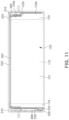
- FIGS. 10 and 11 illustrate a state in which the auxiliary thermal blocking member 310 and the upper thermal blocking member 300 are integrally formed.
- FIG. 10 is a partially exploded perspective view of a battery module based on some embodiments of the disclosed technology.
- FIG. 11 is a cross-sectional view of a battery module based on some embodiments of the disclosed technology.
- the upper thermal blocking member 300 and the auxiliary thermal blocking member 310 may be connected to each other.
- the auxiliary thermal blocking member 310 may be connected to both end portions of the upper thermal blocking member 300 in the second direction (the Z-axis direction) to cover a portion of the surface of the cell stack 100.
- the position of the auxiliary thermal blocking member 310 may be more stably maintained in a thermal runaway situation, and thus, the battery cells 110 may be more effectively protected.
- the battery module 10 may suppress propagation of flames or gas between neighboring battery cells 110 through the thermal blocking member 120 disposed between the battery cells 110.
- thermal blocking member 120 since at least a portion of the thermal blocking member 120 is inserted into the busbar frame 220, a short circuit between two adjacent busbars 210 may be prevented in a thermal runaway situation.
- thermal blocking member 120 includes the blocking portions 123 and 124 extending toward the busbar 210 assembly, a flow of high-temperature gas or flames in the vicinity of the cell stack 100 may be prevented in a thermal runaway situation.
- the blocking portions 123 and 124 of the thermal blocking member 120 block the flow of high-temperature gas or flames in the cell stacking direction in the vicinity of the cell stack 100 in a thermal runaway situation and guide gas or flames to flow in an upward direction of the battery module 10, gas or flames may be guided to be safely discharged to the outside.
- the battery module 10 further includes the auxiliary thermal blocking members 310 and 320 protecting the side surface of the cell stack 100 and the upper thermal blocking member 300 disposed above the cell stack 100, a sequential ignition of the battery cells 110 by gas or flames may be prevented.
- the battery module capable of guiding a flow path of high-temperature gas or flames occurring in a battery cell to a predetermined path may be implemented.
- the battery module capable of blocking heat propagation between neighboring battery cells and blocking indiscriminate flow of high-temperature gas or flames in the vicinity of a cell stack may be implemented.
- the battery module capable of preventing an electrical short circuit from occurring between busbars in a thermal runaway situation may be provided.
- the disclosed technology can be implemented in rechargeable secondary batteries that are widely used in battery-powered devices or systems, including, e.g., digital cameras, mobile phones, notebook computers, hybrid vehicles, electric vehicles, uninterruptible power supplies, battery storage power stations, and others including battery power storage for solar panels, wind power generators and other green tech power generators.
- the disclosed technology can be implemented in some embodiments to provide improved electrochemical devices such as a battery used in various power sources and power supplies, thereby mitigating climate changes in connection with uses of power sources and power supplies.
- Lithium secondary batteries based on the disclosed technology can be used to address various adverse effects such as air pollution and greenhouse emissions by powering electric vehicles (EVs) as alternatives to vehicles using fossil fuel-based engines and by providing battery-based energy storage systems (ESSs) to store renewable energy such as solar power and wind power.
- EVs electric vehicles
- ESSs battery-based energy storage systems
Landscapes
- Chemical & Material Sciences (AREA)
- Chemical Kinetics & Catalysis (AREA)
- Electrochemistry (AREA)
- General Chemical & Material Sciences (AREA)
- Engineering & Computer Science (AREA)
- Manufacturing & Machinery (AREA)
- Battery Mounting, Suspending (AREA)
- Connection Of Batteries Or Terminals (AREA)
Abstract
Description
- Secondary batteries may be recharged and discharged repeatedly, and thus may be used in various devices and systems for supplying electrical power, such as digital cameras, mobile phones, laptop computers, hybrid vehicles, and electric vehicles. Examples of the secondary batteries include nickel-cadmium batteries, nickel-metal hydride batteries, nickel-hydrogen batteries, and lithium secondary batteries.
- The disclosed technology may be implemented in some embodiments to provide a battery module capable of inducing a high-temperature gas or flames occurring in a battery cell to flow along a preset path.
- The disclosed technology may also be implemented in some embodiments to provide a battery module capable of blocking heat propagation between neighboring battery cells and preventing a high-temperature gas or flames from flowing in the vicinity of a cell stack.
- The disclosed technology may also be implemented in some embodiments to provide a battery module capable of preventing an electrical short circuit from occurring between busbars in a thermal runaway situation.
- In an aspect of the disclosed technology, a battery module includes: a housing having an internal space; a cell stack accommodated in the internal space, in which a plurality of battery cells and a plurality of thermal blocking members are stacked in a first direction; a plurality of busbars electrically connected to the plurality of battery cells; and a busbar frame supporting the plurality of busbars, wherein the plurality of battery cells respectively include an electrode assembly and an electrode accommodating portion accommodating the electrode assembly, at least one of the plurality of thermal blocking members includes: a body portion disposed to face the electrode accommodating portion and configured to block heat propagation between the plurality of battery cells; and a blocking portion extending from the body portion in a second direction, perpendicular to the first direction, and configured to at least partially block gas flow in the first direction.
- An end portion of the blocking portion may be adjacent to the busbar frame.
- A material of the plurality of thermal blocking members may include at least one of mica, ceramic wool, or aerogel.
- The blocking portion may include: a first blocking portion formed on one side of the body portion and having at least a portion inserted into the busbar frame; and a second blocking portion formed on the other side, opposite to the one side of the body portion.
- At least a portion of the first blocking portion may be disposed between the plurality of busbars.
- The first blocking portion may include: a first end portion facing an inner surface of the busbar frame in the second direction; and a second end portion protruding further in the second direction than the plurality of busbars.
- The busbar frame may include an insertion recess into which the second end portion of the blocking portion is inserted.
- The first blocking portion further may include a step portion connecting the first end portion to the second end portion.
- The housing may include an upper case portion and a lower case portion configured to cover upper and lower portions of the cell stack, respectively, and the upper case portion may include a venting hole configured to allow gas to be discharged therethrough.
- A venting flow path may be formed in a space between the first end portion and the upper case portion.
- The busbar frame may include: a first busbar frame disposed on one side of the cell stack; a second busbar frame disposed on the other side opposite to the one side of the cell stack; and a connection frame connecting the first busbar frame to the second busbar frame.
- The plurality of thermal blocking members may include: a first thermal blocking member in which the first blocking portion is inserted into the first busbar frame; and a second thermal blocking member in which the first blocking portion is inserted into the second busbar frame.
- The first thermal blocking member and the second thermal blocking member may be alternately disposed in the first direction.
- An end portion of the second blocking portion of the first thermal blocking member may be adjacent to the second busbar frame.
- The battery module may further include: a third thermal blocking member disposed between the busbar frame and the first end portion and extending in the first direction.
- The battery module may further include: a fourth thermal blocking member facing the cell stack in a third direction perpendicular to both the first and second directions.
- The third thermal blocking member and the fourth thermal blocking member may be integrally formed.
- Certain aspects, features and other advantages of the disclosed technology are illustrated by the following detailed description with reference to the accompanying drawings.
-
FIG. 1 is a perspective view of a battery module implemented based on some embodiments of the disclosed technology. -
FIG. 2 is an exploded perspective view of a battery module implemented based on some embodiments of the disclosed technology. -
FIG. 3 illustrates an arrangement of a battery cell, a thermal blocking member, and a busbar assembly based on some embodiments of the disclosed technology. -
FIG. 4 is a perspective view of a battery cell included in a cell stack based on some embodiments of the disclosed technology. -
FIG. 5 is a diagram illustrating an arrangement of a thermal blocking member and a battery cell based on some embodiments of the disclosed technology. -
FIG. 6 is a diagram illustrating formation of a venting flow path by a thermal blocking member based on some embodiments of the disclosed technology. -
FIG. 7 is a cross-sectional view along line I-I' ofFIG. 1 . -
FIG. 8 is a partially exploded perspective view of a battery module based on some embodiments of the disclosed technology. -
FIG. 9 is a cross-sectional view of a battery module based on some embodiments of the disclosed technology. -
FIG. 10 is a partially exploded perspective view of a battery module based on some embodiments of the disclosed technology. -
FIG. 11 is a cross-sectional view of a battery module based on some embodiments of the disclosed technology. - Various circumstances exist in which secondary batteries may be overheated and, in some instances, may become an ignition source, among others, for example, (1) a battery cell reaches the end of life, (2) a swelling phenomenon occurs in the battery cell due to decomposition battery materials including gases generated from such decomposition, (3) the battery cell is overcharged, (4) the battery cell is exposed to heat, (5) battery structure damages, e.g., when a sharp object, such as a nail, penetrates an outer casing material of the battery cell, or (6) an external impact is applied to the battery cell, the battery cell may cause ignition. Flames or a high-temperature gas spouted from the battery cell may cause a chain ignition of other adjacent battery cells accommodated in the battery device and may cause thermal runaway.
- In such cases, flames, high-temperature gases, and conductive particles spouted from the battery cell freely flow inside a battery module and may directly ignite other adjacent battery cells or cause a short circuit between components of the battery module, resulting in further deterioration of the thermal runaway situation.
- The disclosed technology can be implemented in some embodiments to provide a discharge structure that can discharge flames or high-temperature gases spouted from the battery cell that otherwise would have affected other battery cells. In addition, the disclosed technology can be implemented in some embodiments to provide a structure that can block the flow of flames or high-temperature gases inside the battery module and/or induce them to flow in a safe path.
-
FIG. 1 is a perspective view of thebattery module 10 implemented based on some embodiments of the disclosed technology.FIG. 2 is an exploded perspective view of thebattery module 10 implemented based on some embodiments of the disclosed technology. - The
battery module 10 may include ahousing 500 having an internal space, a plurality ofbattery cells 110 accommodated in the internal space, abusbar assembly 200 electrically connected to thebattery cells 110, and anend cover 600 coupled to at least one side of thehousing 500. - The plurality of
battery cells 110 accommodated in thebattery module 10 may be stacked in one direction (e.g., an X-axis direction ofFIG. 2 ) to form at least a portion of thecell stack 100. In some implementations, a stacking direction of thebattery cells 110 in which thebattery cells 110 are stacked can be referred to as a first direction or a cell stacking direction. - Each
battery cell 110 included in thecell stack 100 may output or store electrical energy. The plurality ofbattery cells 110 may be electrically connected to each other through thebusbar assembly 200. At least a portion of thebusbar assembly 200 may be disposed to face thecell stack 100 in a direction perpendicular to the cell stacking direction. - The
busbar assembly 200 may include a plurality of electrical conductors or electrically conductive members 210 (referred to as busbars 210) for electrically connecting onebattery cell 110 to anotherbattery cell 110 and abusbar frame 220 supporting the plurality ofbusbars 210. - The
busbar 210 may be formed of an electrically conductive material (e.g., a metal) and may serve to electrically connect the plurality ofbattery cells 110 to each other. Thebusbar 210 may be electrically connected to alead tab 113 of thebattery cell 110. For example, thebusbar 210 may be bonded to thelead tab 113 of thebattery cell 110. Various welding methods including laser welding may be applied to the connection between thebusbar 210 and the lead tab (e.g., 113 ofFIG. 4 ). However, the connection method is not limited to welding, and any connection method capable of electrically conducting two metallic materials may be used. - The
busbar 210 may face the cell stack in a direction (e.g., a Z-axis direction) perpendicular to the first direction (an X-axis direction). In some implementations, a direction in which the busbar and the cell stack face each other can be defined as a second direction. In addition, a direction perpendicular to both the first direction and the second direction is defined as a third direction. For example, the third direction may be a height direction of the battery module and may be a direction in which an upper case portion and a lower case portion face each other. - The
busbar assembly 200 may include a terminal portion electrically connected to an external circuit of thebattery module 10. The terminal portion may be exposed to the outside of thebattery module 10 through anopening 540 of thehousing 500. - The
busbar frame 220 may structurally support thebusbar 210 and may maintain the stability of thebusbar 210 even when there is an external shock or vibration. For example, thebusbar frame 220 may include a plastic material that is lightweight and has excellent mechanical strength, such as polypropylene, polybutylene terephthalate, and modified polyphenylene oxide (MPPO). Therefore, thebusbar frame 220 may structurally support thebusbar 210, while securing insulation. - The
busbar 210 may be fixed to thebusbar frame 220 in various manners. For example, thebusbar 210 may be fixed to thebusbar frame 220 by a heat welding process or an insert injection process. - The
busbar assembly 200 may further include aconnection frame 230 disposed between thecell stack 100 and thehousing 500 and connected to thebusbar frame 220. For example, thebusbar assembly 200 may include a pair of busbar frames 220 facing each other in the second direction with a cell stack interposed therebetween and aconnection frame 230 connected to the pair of busbar frames 220 and facing the cell stack in the third direction. - In some implementations, a sensing module (not shown) capable of sensing a state of the
cell stack 100 may be disposed in theconnection frame 230. The sensing module (not shown) may include at least one of a temperature sensor or a voltage sensor. The sensing module (not shown) may sense or detect a state of thebattery cell 110 and output sensed information to the outside of thebattery module 10. - The
housing 500 provides an internal space in which one ormore cell stacks 100 may be accommodated. Thehousing 500 may be formed of a material having predetermined rigidity to protect thecell stack 100 and other electrical components accommodated in the internal space from external impact. For example, thehousing 500 may include a metal material, such as aluminum. - The
housing 500 may include alower case portion 520 and anupper case portion 510 coupled to each other. However, a structure of thehousing 500 is not limited thereto, and may have any shape as long as the structure has an internal space in which at least onecell stack 100 may be accommodated. For example, thehousing 500 may be configured as an integral monoframe in which theupper case portion 510 and thelower case portion 520 are integrally formed and both sides are open. - The
housing 500 may include aventing hole 530 through which a gas generated by thecell stack 100 is discharged. For example, the ventinghole 530 may have a shape of a hole passing through thelower case portion 520 or theupper case portion 510. - A shielding member may be disposed in the
venting hole 530. The shielding member may be formed of a thin film or sheet or material layer, and may block foreign matter from being introduced from the outside of thebattery module 10. The shielding member may include a material that is lightweight and has excellent impact resistance, heat resistance, or electrical insulation. For example, the shielding member may include a polycarbonate sheet or layer. In the case of thermal runaway of thebattery module 10, at least a portion of the shielding member may be torn so that a gas emitted from thecell stack 100 may pass therethrough properly. - The
end cover 600 may be coupled to one open side of thehousing 500. For example, as shown inFIG. 2 , theend cover 600 may be provided as a pair and the pair of end covers 600 may be coupled to both open sides of thehousing 500, respectively. - In order to prevent an electrical short circuit between the
busbar assembly 200 and thehousing 500, thebattery module 10 may include an insulatingcover 400. For example, the insulatingcover 400 may be disposed to face thebusbar assembly 200 between thebusbar assembly 200 and thehousing 500. The insulatingcover 400 may include an insulating material, and thus may prevent electrical connection between thebusbar assembly 200 and thehousing 500. For example, the insulatingcover 400 may be formed of a plastic injection molding material including polypropylene or modified polyphenylene oxide (MPPO). However, a material of the insulatingcover 400 is not limited thereto. In some implementations, the insulatingcover 400 may be used to prevent an electrical short circuit from occurring between thecell stack 100 and thehousing 500 or between thebusbar 210 and thehousing 500. - In some implementations, a heat dissipation member (not shown) may be disposed between the
cell stack 100 and thehousing 500. In one example, the heat dissipation member may be disposed such that one surface thereof is in contact with thecell stack 100 and the other surface opposite to the one surface is in contact with thehousing 500. In some implementations, the heat dissipation member may be provided as a thermal adhesive. In some implementations, the heat dissipation member may fill a space between thecell stack 100 and thehousing 500 so that heat transfer by conduction may be more actively performed. Accordingly, heat dissipation efficiency of thebattery module 10 may be increased. - When a large number of
battery cells 110 are stacked inside an enclosure of thebattery module 10, there may be a risk that an undesirable event or situation occurring in onebattery cell 110 that may affect another battery cell in thebattery module 10. In addition, high-temperature gas or flames occurring in thebattery cells 110 may irregularly flow around thecell stack 100 and apply impact on thebattery module 10. Alternatively, a short circuit may occur between components inside the battery module 10 (e.g., between a plurality of busbars) due to conductive particles scattered together with gas or flame. In addition, while gas or flames flows in a portion adjacent to thecell stack 100, an unintended heat propagation path may be formed, which may further aggravate a thermal runaway situation. - To prevent this, the
battery module 10 may include a plurality of thermal blockingmembers 120. For example, thecell stack 100 may include the thermal blockingmember 120 disposed between thebattery cells 110. Each thermal blockingmember 120 may include one or more thermal insulating materials with low thermal conductivity to provide the thermal blocking function, such as preventing or significantly reduce the undesired heat propagation between neighboringbattery cells 110. Thethermal blocking member 120 may serve to protect thebattery cell 110 from physical and thermal shock. For example, the thermal blockingmember 120 may be configured to block heat propagation from onebattery cell 110 to anotherbattery cell 110, while absorbing expansion pressure of thebattery cell 110. In some implementations, for example, athermal blocking member 120 may include mica, silicate, graphite, alumina, ceramic wool, super wool, or aerogel. - The
battery module 10 may further include an upper thermal blockingmember 300 facing at least one side of thecell stack 100. For example, the upper thermal blockingmember 300 may be disposed to face thecell stack 100 between thecell stack 100 and theupper case portion 510. The upper thermal blockingmember 300 may cover an upper side of thecell stack 100 to prevent an occurrence of an unexpected heat propagation path between thecell stack 100 and thehousing 500. - The plurality of thermal blocking
members 120 and the upper thermal blockingmember 300 may provide a path for gas or flames around thecell stack 100 to move in a preset direction in a thermal runaway situation. For example, the thermal blockingmember 120 disposed between thebattery cells 110 may guide gas or flames toward the top of thebattery module 10. - Hereinafter, characteristics of the thermal blocking
member 120 included in thebattery module 10 will be described in detail with reference toFIGS. 3 to 6 . -
FIG. 3 illustrates an arrangement of thebattery cell 110, the thermal blocking member 120 (e.g., 120a, 120b), and thebusbar assembly 200 by way of example.FIG. 4 is a perspective view of thebattery cell 110 included in thecell stack 100 based on some embodiments of the disclosed technology.FIG. 5 is a diagram illustrating the arrangement of the thermal blockingmember 120 and thebattery cell 110 based on some embodiments of the disclosed technology.FIG. 6 is a diagram illustrating formation of a venting flow path VP by the thermal blockingmember 120 based on some embodiments of the disclosed technology.FIG. 7 is a cross-sectional view taken along line I-I' ofFIG. 1 . - In some embodiments of the disclosed technology, the thermal blocking
member 120 and thebattery module 10 including the thermal blockingmember 120 may be implemented as will be discussed below with reference toFIGS. 3 to 7 . In some implementations, the thermal blockingmember 120 and thebattery module 10 including the thermal blockingmember 120 illustrated inFIGS. 3 to 7 may correspond to the thermal blockingmember 120 and thebattery module 10 including the thermal blockingmember 120 illustrated inFIGS. 1 to 2 . - The
cell stack 100 may include a plurality ofbattery cells 110 and a plurality of thermal blockingmembers 120 stacked in the first direction (the X-axis direction). - The
battery cell 110 may be configured to convert chemical energy into electrical energy to supply power to an external circuit or receive power from the outside, change electrical energy into chemical energy to store electricity. For example, thebattery cell 110 may be configured as a nickel metal hydride (Ni-MH) battery or a lithium ion (Li-ion) battery capable of charging and discharging, but is not limited thereto. In some embodiments, a plurality ofbattery cells 110 may be electrically connected to each other while being stacked side by side. - Referring to
FIG. 4 , thebattery cell 110 may be a pouch-type secondary battery that includes anelectrode assembly 114 accommodated in apouch 111. - In the pouch-type secondary battery, the
electrode assembly 114 and an electrolyte (not shown) may be accommodated in thepouch 111 formed by forming one sheet or material layer or a plurality of outer casing materials. For example, thepouch 111 may be formed with one or two receiving portions in a sheet or layer of outer casing material and then folding the outer casing material to form a single space by the receiving portions. - The
pouch 111 may include an electrodeaccommodating portion 112 accommodating theelectrode assembly 114 and an electrolyte (not shown), a sealingportion 115 formed in the periphery of theelectrode accommodating portion 112, and alead tab 113 electrically connected to theelectrode assembly 114 and exposed to the outside of thepouch 111. - The electrode
accommodating portion 112 provides an internal space in which theelectrode assembly 114 and an electrolyte (not shown) are accommodated. Theelectrode assembly 114 may include a plurality of positive electrode plates and a plurality of negative electrode plates stacked with a separator interposed therebetween. - A sealing
portion 115 formed by bonding thepouch 111 may be disposed along at least a portion of the circumference of theelectrode accommodating portion 112. A thermal fusion method may be used to bond thepouch 111, but is not limited thereto. - The sealing
portion 115 may include afirst sealing portion 115a formed in a portion in which thelead tab 113 is disposed and asecond sealing portion 115b formed in a portion in which thelead tab 113 is not disposed. - In order to increase bonding reliability of the sealing
portion 115 and minimize the area of the sealingportion 115, the sealingportion 115 may be folded at least once as shown in the partially enlarged view ofFIG. 4 . - In the
battery cell 110, when one sheet or layer of the outer casing material is folded to have a structure surrounding theelectrode assembly 114, there is no need to form a sealing portion in a portion in which the outer casing material is folded. In this case, as shown inFIG. 4 , the sealingportion 115 may be formed only on three external surfaces of theelectrode accommodating portion 112, and afolding portion 118 may be formed on any one external surface of theelectrode accommodating portion 112. - However, the structure of the
battery cell 110 is not limited to the above. For example, theelectrode accommodating portion 112 may be formed by overlapping two sheets of outer casing materials, and sealing portions may be formed on all four surfaces around theelectrode accommodating portion 112. - In addition, the battery cell applied to the battery module based on some example embodiments are not limited to the pouch-type secondary battery described above. For example, the battery cell may be configured as a prismatic can-type secondary battery, or a plurality of pouch-type secondary batteries may be grouped and formed as a bundle.
- The
cell stack 100 may further include a plurality of thermal blockingmembers 120 facing the plurality ofbattery cells 110 in the first direction. Referring toFIG. 3 , the plurality of thermal blockingmembers 120 may be arranged side by side at predetermined intervals in a cell stacking direction (e.g., the X-axis direction ofFIG. 3 ). One ormore battery cells 110 may be disposed between two adjacent thermal blockingmembers 120. In the drawing, fourbattery cells 110 are stacked between twothermal blocking members 120, but this is only an example, and three or less or five ormore battery cells 110 may be disposed between twothermal blocking members 120. - The
thermal blocking member 120 may block heat and/or flame propagation betweenadjacent battery cells 110. - The
thermal blocking member 120 may include a material having at least one of flame retardancy, heat resistance, heat insulation, or insulating properties. Here, heat resistance may refer to properties that do not melt and do not change in shape even at a temperature of 300°C or higher, and heat insulation may refer to properties that have a thermal conductivity of 1.0 W/mK or less. For example, the thermal blockingmember 120 may include at least one of mica, silicate, graphite, alumina, ceramic wool, super wool, or aerogel. - However, a material of the thermal blocking
member 120 is not limited to the materials described above, and any material may be used as long as it can maintain its shape in a thermal runaway situation of thebattery cell 110 and prevent propagation of heat or flames to otheradjacent battery cells 110. - In order to maximize energy density of the
cell stack 100, a thickness of the thermal blockingmember 120 may be less than a thickness of onebattery cell 110. Here, the thickness may refer to a length in the cell stacking direction. - In some implementations, the thermal blocking
member 120 may include a combination of members having different properties. For example, the thermal blockingmember 120 may be configured by combining a material for thermal blocking as described above and a material having a predetermined elastic force. - For example, the thermal blocking
member 120 may further include at least one of polyurethane, silicone, or rubber (EPDM), and may press thebattery cell 110 using elasticity of these materials. - Referring to
FIGS. 3 and5 , the thermal blockingmember 120 may include abody portion 121 facing theelectrode accommodating portion 112 of thebattery cell 110 and blockingportions body portion 121. -
FIG. 5 is a view illustrating the thermal blockingmember 120 and thebattery cell 110 in a stacked state viewed in the cell stacking direction (the X-axis direction). - The
body portion 121 of the thermal blockingmember 120 faces theelectrode accommodating portion 112 in the first direction (the X-axis direction), and may block heat propagation between neighboringbattery cells 110. - The blocking
portions member 120 may refer to portions extending in the second direction (the Z-axis direction) from both ends of thebody portion 121. As the blockingportions member 120 in the second direction (the Z-axis direction) based on some example embodiments may be longer than a length of theelectrode accommodating portion 112 in the second direction (the Z-axis direction). For example, the blockingportions body portion 121 in the second direction (the Z-axis direction) so that end portions thereof are adjacent to thebusbar frame 220. - The blocking
portions first blocking portion 123 at least partially inserted into thebusbar frame 220 and asecond blocking portion 124 provided on the opposite side of thefirst blocking portion 123 based on thebody portion 121. - A portion of the
first blocking portion 123 may be inserted into thebusbar frame 220 and protrude further in the second direction (the Z-axis direction) than thebusbar 210. - For example, the
first blocking portion 123 may have afirst end portion 123b facing an inner surface of thebusbar frame 220 in the second direction (the Z-axis direction) and asecond end portion 123a further protruding in the second direction (the Z-axis direction) than the first end portion and inserted into thebusbar frame 220. Due to a positional difference between thefirst end portion 123b and thesecond end portion 123a, astep portion 123c may be formed between thefirst end portion 123b and thesecond end portion 123a. - The
second end portion 123a of thefirst blocking portion 123 may be inserted into thebusbar frame 220. Aninsertion groove 222 into which thesecond end portion 123a is inserted may be disposed in thebusbar frame 220. In addition, a slit opening 221 into which thelead tab 113 of thebattery cell 110 is inserted may be disposed in thebusbar frame 220. - In a case where the
second end portion 123a of thefirst blocking portion 123 is inserted into thebusbar frame 220, thesecond end portion 123a of thefirst blocking portion 123 may protrude further in the second direction (the Z-axis direction) than thebusbar 210. That is, a distance between a side surface of thehousing 500 and thesecond end portion 123a in the second direction (the Z-axis direction) may be less than a distance between the side surface of thehousing 500 and thebusbar 210 in the second direction (the Z-axis direction). - A region having the
second end portion 123a in thefirst blocking portion 123 may be inserted into thebusbar frame 220 and disposed between twoadjacent busbars 210. Accordingly, thefirst blocking portion 123 may prevent physical contact between the twobusbars 210. - In some implementations, since the
second end portion 123a of thefirst blocking portion 123 is configured to protrude further in the second direction (the Z-axis direction) than thebusbar 210, the occurrence of an unexpected short circuit between thebusbars 210 in a thermal runaway situation may be physically prevented. - When the
first blocking portion 123 is formed on one side of thebody portion 121, thesecond blocking portion 124 may be formed on the other side opposite to one side of thebody portion 121. Unlike thefirst blocking portion 123, thesecond blocking portion 124 may not have a portion inserted into thebusbar frame 220. However, in some implementations, a portion of thesecond blocking portion 124 may be inserted into thebusbar frame 220. - An end portion of the
second blocking portion 124 may be disposed to face an inner surface of thebusbar frame 220 so as not to interfere with thebusbar 210. - In the plurality of blocking
portions first blocking portion 123 of one of thethermal blocking members 120 is inserted into thefirst busbar frame 220, and thefirst blocking portion 123 of the other of thethermal blocking members 120 may be inserted into thesecond busbar frame 220. For example, referring toFIG. 3 , a pair of busbar frames 220 may include afirst busbar frame 220a and asecond busbar frame 220b spaced apart from each other in the second direction (the Z-axis direction), and the plurality of thermal blockingmembers 120 may include a first thermal blockingmember 120a in which thefirst blocking portion 123 is inserted into thefirst busbar frame 220a and a second thermal blockingmember 120b in which thefirst blocking portion 123 is inserted into thesecond busbar frame 220b. - In order to avoid interference with the
busbar 210, the first thermal blockingmember 120a and the second thermal blockingmember 120b may be alternately disposed in the first direction (the X-axis direction). - The
first blocking portion 123 and thesecond blocking portion 124 may serve to block gas or flames occurring in a thermal runaway situation from flowing in the first direction (the X-axis direction) in the vicinity of the cell stack. Since the flow of gas or flames in the first direction (the X-axis direction) is blocked by thefirst blocking portion 123 and thesecond blocking portion 124, the gas or flames may be naturally guided to flow in a direction (for example, a third direction (a Y-axis direction) in which the upper case portion and the lower case portion face each other) perpendicular to the first direction (the X-axis direction). - In this manner, the
battery module 10 based on some example embodiments includes the thermal blockingmember 120 having the blockingportions cell stack 100 may be suppressed in a thermal runaway situation. - In particular, the thermal blocking
member 120 based on some example embodiments extends in length to thebusbar frame 220 to block undesirable flow of high-temperature gas or flames between thebusbar frame 220 and thecell stack 100 and guide a flow path thereof in a certain direction. -
FIGS. 6 and7 illustrate a flow path of gas and/or flames described above. Referring toFIGS. 6 and7 , the venting flow path VP through which gas or flames flow may have a specific position or path that is determined by the blockingportions member 120. - Since the blocking
portions member 120 have properties, such as flame retardancy, heat resistance, and heat insulation, the blockingportions cell stack 100 may be blocked by the blockingportions member 120 and flow along surfaces of the blockingportions - For example, since the blocking
portions busbar frame 220, the venting flow path VP may be formed to connect to the outside thebusbar frame 220 by the blockingportions FIG. 7 , some of the venting flow paths VP may be formed in a space between the external surface of thebusbar frame 220 and thehousing 500. - Alternatively, as shown in
FIG. 7 , the venting flow path VP formed inside thebusbar frame 220 may be blocked in a flow in the first direction (the X-axis direction) by the blockingportions battery module 10. That is, the blockingportions body portion 121 blocks the flow of gas or flames in the first direction (the X-axis direction) perpendicular to the second direction (the Z-axis direction) and allows gas or flames to flow in the third direction (the Y-axis direction). - In particular, as gas or flames continuously occur, the thermal blocking
member 120 may guide a flow of gas or flames toward the upper side of thebattery module 10. - In this manner, the thermal blocking
member 120 may prevent gas or flames from spreading in the cell stacking direction in the vicinity of thecell stack 100, thereby preventing thebattery cells 110 from being sequentially ignited by gas or flames. - The
busbar frame 220 may be formed of a material relatively vulnerable to high temperatures than the thermal blockingmember 120. For example, when thebusbar frame 220 includes a plastic material, thebusbar frame 220 may be structurally collapsed by high-temperature gas or flames occurring in a thermal runaway situation. In this case, there is a risk that gas or flames may spread through an empty space formed as thebusbar frame 220 collapses. In this situation, the thermal blockingmember 120 may guide a flow path of gas or flames to a safe path. - For example, the inset on the left in
FIG. 6 illustrates an example of thebusbar frame 220 before a thermal runaway situation occurs, and the inset on the right inFIG. 6 illustrates an example of thebusbar frame 220 that has been melted in the thermal runaway situation. - Referring to
FIG. 6 , when thebusbar frame 220 is melted by high-temperature gas or flames, the venting flow path VP may be formed through a space occupied by thebusbar frame 220. - In this situation, the thermal blocking
member 120 may block an electrical short circuit between thebusbars 210 caused by flowing gas or flames. - For example, as shown in
FIG. 6 , some venting flow paths VP may be formed to face in the third direction (the Y-axis direction) along the thermal blockingmember 120, and some other venting flow paths VP may be formed to face in the first direction (the X-axis direction) along the empty space in which thebusbar frame 220 has been melted (e.g., a passage surrounded by thefirst end portion 123b of the thermal blockingmember 120, thestep portion 123c, and the housing 500). - The gas or flames guided to flow upwardly by the thermal blocking
member 120 avoids thebusbar 210 along the venting flow path VP facing in the first direction (the X-axis direction) to flow either in a forward direction or a backward direction of thebattery module 10. Accordingly, an electrical short circuit that may be caused by gas, flames, and combustion scattering products between twoadjacent busbars 210 may be prevented. - In some implementations, when the
venting hole 530 is formed in theupper case portion 510, gas or flames flowing along the venting flow path VP may be safely discharged to the outside through theventing hole 530. - In this case, to facilitate discharge, the venting flow path VP may be formed to flow along a lower portion of the
venting hole 530. For example, thestep portion 123c of the thermal blockingmember 120 may be formed to overlap theventing hole 530 in the third direction (the Y-axis direction), so that the venting flow path VP may be guided to be formed below the ventinghole 530. - In some example embodiments, the battery module may further include an auxiliary thermal blocking member to more effectively protect the
battery cell 110 from high-temperature gas or flames in a thermal runaway situation. Hereinafter, a battery module based on some example embodiments will be described with reference toFIGS. 8 to 11 . -
FIG. 8 is a partially exploded perspective view of a battery module based on some embodiments of the disclosed technology.FIG. 9 is a cross-sectional view of a battery module based on some embodiments of the disclosed technology. - As described above with reference to
FIGS. 6 and7 , the thermal blockingmember 120 included in thecell stack 100 may guide a flow path of a high-temperature gas or flames to be formed in a predetermined position (e.g., near an upper corner inside the battery module 10). - In this case, in order to further reduce the effect of high-temperature gas or flames on the
cell stack 100, the battery module may further include a third thermal blockingmember 320 disposed on one side of thecell stack 100. - In some implementations, the term "thermal blocking
member 120" may be used to indicate athermal blocking member 120 disposed between thebattery cells 110. In addition, in some implementations, different from the thermal blockingmember 120 disposed between thebattery cells 110, the third thermal blockingmember 320 may also be referred to as "auxiliary thermal blocking member." In addition, in some implementations, the upper thermal blockingmember 300 described above may correspond to a fourth thermal blockingmember 300. - In addition, in some implementations, components (e.g., the
cell stack 100, thebusbar 210, thebusbar frame 220, thethermal blocking members 120, etc.) in the battery module ofFIGS. 8 and9 , other than the auxiliary thermal blockingmember 320, correspond to the components of thebattery module 10 ofFIGS. 1 to 7 . - The auxiliary thermal blocking
member 320 may be disposed in a position different from that of the upper thermal blockingmember 300. For example, the upper thermal blockingmember 300 may be disposed to face thecell stack 100 in the third direction (the Y-axis direction), and the auxiliary thermal blockingmember 320 may be disposed to face thecell stack 100 in the second direction (the Z-axis direction). - The auxiliary thermal blocking
member 320 may be disposed in a position in which the auxiliary thermal blockingmember 320 is not interfered with the thermal blockingmember 120. For example, the auxiliary thermal blockingmember 320 may be disposed to extend in the first direction (the X-axis direction) between thefirst end portion 123b of the thermal blockingmember 120 and thebusbar frame 220. In this case, the auxiliary thermal blockingmember 320 may face thestep portion 123c of the thermal blockingmember 120 in the third direction (the Y-axis direction). - Materials of the upper thermal blocking
member 300 and the auxiliary thermal blockingmember 320 may be the same as those of the thermal blockingmember 120 described above with reference toFIGS. 1 to 7 . That is, the upper thermal blockingmember 300 and the auxiliary thermal blockingmember 320 may be configured to have at least one or more properties of flame retardancy, heat resistance, heat insulation, and insulating properties, so that thebattery cells 110 may be protected in a thermal runaway situation. For example, the upper thermal blockingmember 300 and the auxiliary thermal blockingmember 320 may include at least one of mica, silicate, graphite, alumina, ceramic wool or super wool, or aerogel. - The venting flow path VP may be formed outside the auxiliary thermal blocking
member 320. For example, the venting flow path VP may be formed in a space between the auxiliary thermal blockingmember 320 and theupper case portion 510. The auxiliary thermal blockingmember 320 may block high-temperature gas or flames flowing through the venting flow path VP from directly contacting thecell stack 100, thereby preventing thebattery cells 110 from being sequentially ignited by gas or flames. - Since the auxiliary thermal blocking
member 320 extends in the first direction (the X-axis direction) from the side surface of thecell stack 100, the side surface of thecell stack 100 may be effectively protected from gas or flames flowing in the first direction (the X-axis direction) along a space in which thebusbar frame 220 collapses. - In particular, as described above with reference to
FIGS. 6 and7 , when the venting flow path VP is formed at the upper corner of thebattery module 10, the auxiliary thermal blockingmember 320 disposed between thecell stack 100 and the venting flow path VP may protect thebattery cells 110 from high-temperature gas or flames flowing through the venting flow path VP. - Inn another example embodiment, the auxiliary thermal blocking member may be integrally formed with the upper thermal blocking
member 300. For example,FIGS. 10 and11 illustrate a state in which the auxiliary thermal blockingmember 310 and the upper thermal blockingmember 300 are integrally formed. -
FIG. 10 is a partially exploded perspective view of a battery module based on some embodiments of the disclosed technology.FIG. 11 is a cross-sectional view of a battery module based on some embodiments of the disclosed technology. - In the battery module described in
FIGS. 10 and11 , characteristics other than that the auxiliary thermal blockingmember 310 and the upper thermal blockingmember 300 are integrally formed are the same as those of the battery module described above with reference toFIGS. 8 and9 above. Accordingly, redundant descriptions ofFIGS. 8 and9 may be omitted. - The upper thermal blocking
member 300 and the auxiliary thermal blockingmember 310 may be connected to each other. For example, when the upper thermal blockingmember 300 faces thecell stack 100 in the third direction (the Y-axis direction), the auxiliary thermal blockingmember 310 may be connected to both end portions of the upper thermal blockingmember 300 in the second direction (the Z-axis direction) to cover a portion of the surface of thecell stack 100. - As the upper thermal blocking
member 300 and the auxiliary thermal blockingmember 310 are integrally formed with each other, the position of the auxiliary thermal blockingmember 310 may be more stably maintained in a thermal runaway situation, and thus, thebattery cells 110 may be more effectively protected. - In some example embodiments, the
battery module 10 may suppress propagation of flames or gas between neighboringbattery cells 110 through the thermal blockingmember 120 disposed between thebattery cells 110. - In addition, since at least a portion of the thermal blocking
member 120 is inserted into thebusbar frame 220, a short circuit between twoadjacent busbars 210 may be prevented in a thermal runaway situation. - In addition, since the thermal blocking
member 120 includes the blockingportions busbar 210 assembly, a flow of high-temperature gas or flames in the vicinity of thecell stack 100 may be prevented in a thermal runaway situation. - In addition, since the blocking
portions member 120 block the flow of high-temperature gas or flames in the cell stacking direction in the vicinity of thecell stack 100 in a thermal runaway situation and guide gas or flames to flow in an upward direction of thebattery module 10, gas or flames may be guided to be safely discharged to the outside. - In addition, since the
battery module 10 further includes the auxiliary thermal blockingmembers cell stack 100 and the upper thermal blockingmember 300 disposed above thecell stack 100, a sequential ignition of thebattery cells 110 by gas or flames may be prevented. - In some example embodiments, the battery module capable of guiding a flow path of high-temperature gas or flames occurring in a battery cell to a predetermined path may be implemented.
- In addition, the battery module capable of blocking heat propagation between neighboring battery cells and blocking indiscriminate flow of high-temperature gas or flames in the vicinity of a cell stack may be implemented.
- In addition, the battery module capable of preventing an electrical short circuit from occurring between busbars in a thermal runaway situation may be provided.
- The disclosed technology can be implemented in rechargeable secondary batteries that are widely used in battery-powered devices or systems, including, e.g., digital cameras, mobile phones, notebook computers, hybrid vehicles, electric vehicles, uninterruptible power supplies, battery storage power stations, and others including battery power storage for solar panels, wind power generators and other green tech power generators. Specifically, the disclosed technology can be implemented in some embodiments to provide improved electrochemical devices such as a battery used in various power sources and power supplies, thereby mitigating climate changes in connection with uses of power sources and power supplies. Lithium secondary batteries based on the disclosed technology can be used to address various adverse effects such as air pollution and greenhouse emissions by powering electric vehicles (EVs) as alternatives to vehicles using fossil fuel-based engines and by providing battery-based energy storage systems (ESSs) to store renewable energy such as solar power and wind power.
Claims (15)
- A battery module comprising:a housing structured to provide an enclosure with an internal space;a cell stack accommodated in the internal space of the housing and including a plurality of battery cells stacked in a first direction and a plurality of thermal blocking members disposed between battery cells in the plurality of battery cells;a plurality of electrically conductive members electrically connected to the plurality of battery cells of the cell stack; anda frame coupled to and structured to support the plurality of electrically conductive members,wherein each of the plurality of battery cells of the cell stack includes an electrode assembly and an electrode accommodating portion accommodating the electrode assembly,wherein at least one of the plurality of thermal blocking members of the cell stack includes:a body portion disposed to face the electrode accommodating portion and configured to block heat propagation between the plurality of battery cells; andone or more blocking portions extending from the body portion in a second direction that is perpendicular to the first direction, the one or more blocking portions configured to at least partially block a gas flow in the first direction.
- The battery module of claim 1, wherein the blocking portion includes an end portion that is adjacent to the frame.
- The battery module of any one of claims 1 or 2, wherein the plurality of thermal blocking members includes a material that includes at least one of mica, ceramic wool, or aerogel.
- The battery module of any one of claims 1 to 3, wherein the one or more blocking portions include:a first blocking portion formed on one side of the body portion and including at least a portion that is configured to be inserted into the frame; anda second blocking portion formed on another side opposite to the one side of the body portion.
- The battery module of claim 4, wherein the first blocking portion includes:a first end portion facing an inner surface of the frame in the second direction; anda second end portion disposed between the plurality of electrically conductive members.
- The battery module of claim 5, wherein the frame includes an insertion recess into which the second end portion of the blocking portion is inserted.
- The battery module of any one of claims 5 or 6, wherein the first blocking portion further includes a step portion connecting the first end portion to the second end portion.
- The battery module of any one of claims 1 to 7, whereinthe housing includes an upper case portion and a lower case portion configured to cover upper and lower portions of the cell stack, respectively, andthe upper case portion includes a venting hole configured to allow gas to be discharged therethrough.
- The battery module of claim 8, further comprising a venting flow path formed in a space between the first end portion and the upper case portion.
- The battery module of any one of claim 1 to 9, wherein the frame includes:a first frame disposed on one side of the cell stack;a second frame disposed on another side opposite to the one side of the cell stack; anda connection frame connecting the first frame to the second frame.
- The battery module of claim 10, wherein the plurality of thermal blocking members include:a first thermal blocking member in which the first blocking portion is inserted into the first frame; anda second thermal blocking member in which the first blocking portion is inserted into the second frame, andwherein the first thermal blocking member and the second thermal blocking member are alternately disposed in the first direction
- The battery module of claim 11, wherein an end portion of the second blocking portion of the first thermal blocking member is adjacent to the second frame.
- The battery module of any one of claims 5 to 12, further comprising:
a third thermal blocking member disposed between the frame and the first end portion and extending in the first direction. - The battery module of claim 13, further comprising:
a fourth thermal blocking member facing the cell stack in a third direction perpendicular to both the first and second directions. - The battery module of claim 14, wherein the third thermal blocking member and the fourth thermal blocking member are integrally formed.
Applications Claiming Priority (1)
| Application Number | Priority Date | Filing Date | Title |
|---|---|---|---|
| KR1020220160828A KR20240078161A (en) | 2022-11-25 | 2022-11-25 | Battery module |
Publications (1)
| Publication Number | Publication Date |
|---|---|
| EP4376176A1 true EP4376176A1 (en) | 2024-05-29 |
Family
ID=87847871
Family Applications (1)
| Application Number | Title | Priority Date | Filing Date |
|---|---|---|---|
| EP23193625.3A Pending EP4376176A1 (en) | 2022-11-25 | 2023-08-28 | Battery module |
Country Status (4)
| Country | Link |
|---|---|
| US (2) | US12230778B2 (en) |
| EP (1) | EP4376176A1 (en) |
| KR (1) | KR20240078161A (en) |
| CN (2) | CN221304823U (en) |
Families Citing this family (3)
| Publication number | Priority date | Publication date | Assignee | Title |
|---|---|---|---|---|
| KR20250173869A (en) * | 2024-06-04 | 2025-12-11 | 주식회사 엘지에너지솔루션 | Battery pack and vehicle including the same |
| US20260058254A1 (en) * | 2024-08-21 | 2026-02-26 | Sk On Co., Ltd. | Battery assembly |
| WO2026089357A1 (en) * | 2024-10-25 | 2026-04-30 | 주식회사 엘지에너지솔루션 | Battery module, battery pack and vehicle including same |
Citations (4)
| Publication number | Priority date | Publication date | Assignee | Title |
|---|---|---|---|---|
| US20210320374A1 (en) * | 2019-03-06 | 2021-10-14 | Lg Chem, Ltd. | Ess module having structure capable of preventing external exposure of flame and ess pack including the same |
| WO2022182016A1 (en) * | 2021-02-24 | 2022-09-01 | 주식회사 엘지에너지솔루션 | Battery module and battery pack including same |
| EP4270592A1 (en) * | 2022-04-20 | 2023-11-01 | SK On Co., Ltd. | Battery module having sensing module assembly |
| EP4300662A2 (en) * | 2022-06-07 | 2024-01-03 | SK On Co., Ltd. | Battery module |
Family Cites Families (2)
| Publication number | Priority date | Publication date | Assignee | Title |
|---|---|---|---|---|
| KR20220029482A (en) | 2020-08-31 | 2022-03-08 | 주식회사 엘지에너지솔루션 | Battery module and battery pack including the same |
| WO2023191467A1 (en) * | 2022-03-31 | 2023-10-05 | 주식회사 엘지에너지솔루션 | Battery module with enhanced safety |
-
2022
- 2022-11-25 KR KR1020220160828A patent/KR20240078161A/en active Pending
-
2023
- 2023-08-28 EP EP23193625.3A patent/EP4376176A1/en active Pending
- 2023-08-28 US US18/457,095 patent/US12230778B2/en active Active
- 2023-11-24 CN CN202323186252.1U patent/CN221304823U/en active Active
- 2023-11-24 CN CN202311582881.8A patent/CN118099622A/en active Pending
-
2025
- 2025-02-03 US US19/044,396 patent/US20250201971A1/en active Pending
Patent Citations (4)
| Publication number | Priority date | Publication date | Assignee | Title |
|---|---|---|---|---|
| US20210320374A1 (en) * | 2019-03-06 | 2021-10-14 | Lg Chem, Ltd. | Ess module having structure capable of preventing external exposure of flame and ess pack including the same |
| WO2022182016A1 (en) * | 2021-02-24 | 2022-09-01 | 주식회사 엘지에너지솔루션 | Battery module and battery pack including same |
| EP4270592A1 (en) * | 2022-04-20 | 2023-11-01 | SK On Co., Ltd. | Battery module having sensing module assembly |
| EP4300662A2 (en) * | 2022-06-07 | 2024-01-03 | SK On Co., Ltd. | Battery module |
Also Published As
| Publication number | Publication date |
|---|---|
| KR20240078161A (en) | 2024-06-03 |
| CN118099622A (en) | 2024-05-28 |
| US12230778B2 (en) | 2025-02-18 |
| CN221304823U (en) | 2024-07-09 |
| US20240178486A1 (en) | 2024-05-30 |
| US20250201971A1 (en) | 2025-06-19 |
Similar Documents
| Publication | Publication Date | Title |
|---|---|---|
| CN216698555U (en) | Battery module and battery pack including the same | |
| JP7580837B2 (en) | Battery module and battery pack including same | |
| US12230778B2 (en) | Battery module | |
| JP7546983B2 (en) | Battery module and battery pack including same | |
| JP7652510B2 (en) | Battery module and battery pack including same | |
| US20230282929A1 (en) | Battery module and battery pack including the same | |
| US12308405B2 (en) | Battery module | |
| EP4246669A2 (en) | Battery module | |
| KR102867400B1 (en) | Battery module and battery pack including the same | |
| US12230845B2 (en) | Eco-friendly power source such as battery module for transportation vehicle | |
| KR102880677B1 (en) | Battery module and, battery pack and vehicle including same | |
| JP7662270B2 (en) | Battery pack and device including same | |
| JP7708497B2 (en) | Battery pack and device including same | |
| US20250219197A1 (en) | Battery module and battery pack with thermally conductive polymer | |
| US20260135196A1 (en) | Battery Module and Battery Pack Including Protective Member | |
| EP4738554A1 (en) | Cap assembly and battery cell comprising the same | |
| US20250253478A1 (en) | Battery assembly | |
| KR20260043853A (en) | Battery module and battery pack comprising the same | |
| KR20260069496A (en) | Battery pack and device including the same | |
| KR20250128659A (en) | Battery module comprising thermal barrier and battery pack comprising the same | |
| KR20250122229A (en) | Battery module comprising protection sheet and battery pack comprising protection sheet | |
| KR20260069041A (en) | Battery module and battery pack including the protective member | |
| KR20260017188A (en) | Battery module comprising insulating cover, battery pack comprising the same, and battery module manufacturing method | |
| KR20250147389A (en) | Battery pack with improved cooling performance | |
| KR20220161057A (en) | Battery module and battery pack including the same |
Legal Events
| Date | Code | Title | Description |
|---|---|---|---|
| PUAI | Public reference made under article 153(3) epc to a published international application that has entered the european phase |
Free format text: ORIGINAL CODE: 0009012 |
|
| STAA | Information on the status of an ep patent application or granted ep patent |
Free format text: STATUS: THE APPLICATION HAS BEEN PUBLISHED |
|
| AK | Designated contracting states |
Kind code of ref document: A1 Designated state(s): AL AT BE BG CH CY CZ DE DK EE ES FI FR GB GR HR HU IE IS IT LI LT LU LV MC ME MK MT NL NO PL PT RO RS SE SI SK SM TR |
|
| STAA | Information on the status of an ep patent application or granted ep patent |
Free format text: STATUS: REQUEST FOR EXAMINATION WAS MADE |
|
| 17P | Request for examination filed |
Effective date: 20241125 |
|
| RBV | Designated contracting states (corrected) |
Designated state(s): AL AT BE BG CH CY CZ DE DK EE ES FI FR GB GR HR HU IE IS IT LI LT LU LV MC ME MK MT NL NO PL PT RO RS SE SI SK SM TR |