EP4376041A1 - Vacuum circuit breaker - Google Patents
Vacuum circuit breaker Download PDFInfo
- Publication number
- EP4376041A1 EP4376041A1 EP21950948.6A EP21950948A EP4376041A1 EP 4376041 A1 EP4376041 A1 EP 4376041A1 EP 21950948 A EP21950948 A EP 21950948A EP 4376041 A1 EP4376041 A1 EP 4376041A1
- Authority
- EP
- European Patent Office
- Prior art keywords
- vacuum
- vacuum valve
- circuit breaker
- tank
- movable
- Prior art date
- Legal status (The legal status is an assumption and is not a legal conclusion. Google has not performed a legal analysis and makes no representation as to the accuracy of the status listed.)
- Pending
Links
Images



Classifications
-
- H—ELECTRICITY
- H01—ELECTRIC ELEMENTS
- H01H—ELECTRIC SWITCHES; RELAYS; SELECTORS; EMERGENCY PROTECTIVE DEVICES
- H01H33/00—High-tension or heavy-current switches with arc-extinguishing or arc-preventing means
- H01H33/02—Details
- H01H33/04—Means for extinguishing or preventing arc between current-carrying parts
- H01H33/14—Multiple main contacts for the purpose of dividing the current through, or potential drop along, the arc
-
- H—ELECTRICITY
- H01—ELECTRIC ELEMENTS
- H01H—ELECTRIC SWITCHES; RELAYS; SELECTORS; EMERGENCY PROTECTIVE DEVICES
- H01H33/00—High-tension or heavy-current switches with arc-extinguishing or arc-preventing means
- H01H33/02—Details
- H01H33/53—Cases; Reservoirs, tanks, piping or valves, for arc-extinguishing fluid; Accessories therefor, e.g. safety arrangements, pressure relief devices
-
- H—ELECTRICITY
- H01—ELECTRIC ELEMENTS
- H01H—ELECTRIC SWITCHES; RELAYS; SELECTORS; EMERGENCY PROTECTIVE DEVICES
- H01H33/00—High-tension or heavy-current switches with arc-extinguishing or arc-preventing means
- H01H33/02—Details
- H01H33/04—Means for extinguishing or preventing arc between current-carrying parts
- H01H33/16—Impedances connected with contacts
- H01H33/166—Impedances connected with contacts the impedance being inserted only while closing the switch
-
- H—ELECTRICITY
- H01—ELECTRIC ELEMENTS
- H01H—ELECTRIC SWITCHES; RELAYS; SELECTORS; EMERGENCY PROTECTIVE DEVICES
- H01H33/00—High-tension or heavy-current switches with arc-extinguishing or arc-preventing means
- H01H33/60—Switches wherein the means for extinguishing or preventing the arc do not include separate means for obtaining or increasing flow of arc-extinguishing fluid
- H01H33/66—Vacuum switches
-
- H—ELECTRICITY
- H01—ELECTRIC ELEMENTS
- H01H—ELECTRIC SWITCHES; RELAYS; SELECTORS; EMERGENCY PROTECTIVE DEVICES
- H01H33/00—High-tension or heavy-current switches with arc-extinguishing or arc-preventing means
- H01H33/60—Switches wherein the means for extinguishing or preventing the arc do not include separate means for obtaining or increasing flow of arc-extinguishing fluid
- H01H33/66—Vacuum switches
- H01H33/6606—Terminal arrangements
-
- H—ELECTRICITY
- H01—ELECTRIC ELEMENTS
- H01H—ELECTRIC SWITCHES; RELAYS; SELECTORS; EMERGENCY PROTECTIVE DEVICES
- H01H33/00—High-tension or heavy-current switches with arc-extinguishing or arc-preventing means
- H01H33/60—Switches wherein the means for extinguishing or preventing the arc do not include separate means for obtaining or increasing flow of arc-extinguishing fluid
- H01H33/66—Vacuum switches
- H01H33/666—Operating arrangements
-
- H—ELECTRICITY
- H01—ELECTRIC ELEMENTS
- H01H—ELECTRIC SWITCHES; RELAYS; SELECTORS; EMERGENCY PROTECTIVE DEVICES
- H01H33/00—High-tension or heavy-current switches with arc-extinguishing or arc-preventing means
- H01H33/02—Details
- H01H33/04—Means for extinguishing or preventing arc between current-carrying parts
- H01H33/14—Multiple main contacts for the purpose of dividing the current through, or potential drop along, the arc
- H01H2033/146—Multiple main contacts for the purpose of dividing the current through, or potential drop along, the arc using capacitors, e.g. for the voltage division over the different switches
-
- H—ELECTRICITY
- H01—ELECTRIC ELEMENTS
- H01H—ELECTRIC SWITCHES; RELAYS; SELECTORS; EMERGENCY PROTECTIVE DEVICES
- H01H33/00—High-tension or heavy-current switches with arc-extinguishing or arc-preventing means
- H01H33/60—Switches wherein the means for extinguishing or preventing the arc do not include separate means for obtaining or increasing flow of arc-extinguishing fluid
- H01H33/66—Vacuum switches
- H01H33/666—Operating arrangements
- H01H2033/6667—Details concerning lever type driving rod arrangements
Definitions
- the present disclosure relates to a vacuum circuit breaker including a plurality of vacuum valves.
- Patent Literature 1 discloses a vacuum circuit breaker includes a plurality of vacuum valves connected in series with each other. The plurality of vacuum valves are disposed inside a tank.
- Patent Literature 1 Japanese Patent Application Laid-open No. S58-194225
- the plurality of vacuum valves are disposed in one row on a center axis of the circular cylindrical tank.
- the dimension of the vacuum circuit breaker in a direction of the center axis of the tank inevitably increases by the length of additional vacuum valves. Therefore, according to the conventional technique, the vacuum circuit breaker is significantly increased in size in the direction of the center axis of the tank. As a result, there has been a problem in which a compact configuration is difficult to be achieved.
- the present disclosure has been made in view of the above, and an object of the present disclosure is to obtain a vacuum circuit breaker that enables the achievement of a compact configuration.
- a vacuum circuit breaker includes: a plurality of vacuum valves each of which includes: a vacuum container having a cylindrical shape; a fixed electrode fixed inside the vacuum container; a movable conductor protruding from an inside of the vacuum container to an outside of the vacuum container and movable in a direction of a center axis of the vacuum container; and a movable electrode to move together with the movable conductor inside the vacuum container to be capable of being separated from the fixed electrode and coming into contact with the fixed electrode, the plurality of vacuum valves being connected in series with each other; and a tank that has a cylindrical shape and accommodates the plurality of vacuum valves.
- the plurality of vacuum valves include at least two vacuum valves adjacent to each other in a direction intersecting a center axis of the tank.
- the vacuum circuit breaker according to the present disclosure can acquire an effect that a compact configuration can be achieved.
- FIG. 1 is a diagram illustrating an external view of a vacuum circuit breaker 100 according to a first embodiment.
- the vacuum circuit breaker 100 includes a cylindrical tank 10, two bushings 11 and 12 erected at upper portions of the tank 10 in a vertical direction, an operation device 13, two tubes 14 and 15 erected at lower portions of the tank 10 in the vertical direction, and two current transformers 16 and 17.
- the tank 10 includes a circular cylinder made of a metal material and metal flanges that close ends of the circular cylinder.
- the tank 10 is connected to a reference potential point.
- An insulating gas is enclosed inside the tank 10.
- the tank 10 is supported by a frame 18 erected on an installation surface.
- the current transformer 16 is provided for the bushing 11.
- the current transformer 17 is provided for the bushing 12.
- An X axis, a Y axis, and a Z axis are three axes perpendicular to each other.
- the X axis and the Y axis are horizontal axes.
- the Z axis is a vertical axis.
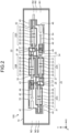
- FIG. 2 is a first top view illustrating an internal configuration of the tank 10 of the vacuum circuit breaker 100 according to the first embodiment.
- FIG. 3 is a first side view illustrating the internal configuration of the tank 10 of the vacuum circuit breaker 100 according to the first embodiment.
- FIG. 4 is a second top view illustrating the internal configuration of the tank 10 of the vacuum circuit breaker 100 according to the first embodiment.
- FIG. 5 is a second side view illustrating the internal configuration of the tank 10 of the vacuum circuit breaker 100 according to the first embodiment.
- FIGS. 2 to 5 some of the constituent elements inside the tank 10 are illustrated in cross section.
- the vacuum circuit breaker 100 includes a vacuum valve 20A that is a first vacuum valve, a vacuum valve 20B that is a second vacuum valve, a vacuum valve 20C that is a third vacuum valve, and a vacuum valve 20D that is a fourth vacuum valve.
- a vacuum valve 20A that is a first vacuum valve
- a vacuum valve 20B that is a second vacuum valve
- a vacuum valve 20C that is a third vacuum valve
- a vacuum valve 20D that is a fourth vacuum valve.
- the four vacuum valves 20A, 20B, 20C, and 20D are each referred to as a vacuum valve 20.
- Each of the vacuum valves 20 constitutes a breaker unit of the vacuum circuit breaker 100.
- Each vacuum valve 20 includes a cylindrical vacuum container 21, a fixed electrode 22 fixed inside the vacuum container 21, and a movable electrode 23 movable inside the vacuum container 21.
- the fixed electrode 22 and the movable electrode 23 of each vacuum valve 20 constitute a breaking point disposed inside the vacuum container 21.
- a center axis N0 of the tank 10 and the respective center axes N1, N2, N3, and N4 of the vacuum containers 21 are all parallel to the X axis.
- FIGS. 2 and 3 illustrate the vacuum circuit breaker 100 in the open state.
- FIGS. 4 and 5 illustrate the vacuum circuit breaker 100 in the closed state.
- an operation of the vacuum circuit breaker 100 when the state is changed from the open state to the closed state is referred to as a closing operation, and an operation of the vacuum circuit breaker 100 when the state is changed from the closed state to the open state is referred to as an opening operation.
- the vacuum circuit breaker 100 closes an electric circuit by the closing operation, and opens the electric circuit by the opening operation. Furthermore, in each vacuum valve 20, a movable electrode 23 side is referred to as a movable side with respect to the fixed electrode 22, and a side opposite to the movable side is referred to as a fixed side.
- the vacuum container 21 includes a circular cylinder made of an insulating material and metal flanges that close ends of the circular cylinder.
- the inside of the vacuum container 21 is maintained at a high vacuum.
- a fixed conductor 24 is disposed inside the vacuum container 21.
- the fixed conductor 24 is disposed at a fixed side end of the vacuum container 21.
- the fixed electrode 22 is fixed to a distal end of the fixed conductor 24.
- a bellows 26 is disposed at a movable side end of the vacuum container 21 inside the vacuum container 21.
- a movable conductor 25 penetrates a movable side end of the vacuum container 21, and protrudes from the inside of the vacuum container 21 to the outside of the vacuum container 21.
- the movable electrode 23 is fixed to a distal end of the movable conductor 25 inside the vacuum container 21.
- the fixed electrode 22, the movable electrode 23, the fixed conductor 24, and the movable conductor 25 are disposed on the center axis of the vacuum container 21.
- the movable conductor 25 reciprocates in the direction of the center axis of the vacuum container 21.
- the movable electrode 23 moves together with the movable conductor 25 inside the vacuum container 21.
- the bellows 26 expands and contracts, following the movement of the movable conductor 25.
- the closing operation the movable electrode 23 moves toward the fixed side, and comes into contact with the fixed electrode 22.
- the opening operation the movable electrode 23 moves toward the movable side, and is separated from the fixed electrode 22.
- the vacuum circuit breaker 100 opens and closes the electric circuit by moving the movable electrode 23 inside each vacuum valve 20.
- Two link mechanisms 27 are disposed inside the tank 10. Furthermore, two support bushings 30 are provided inside the tank 10. One of the two link mechanisms 27 is connected between the movable conductor 25 of the vacuum valve 20A and the movable conductor 25 of the vacuum valve 20C. The other of the two link mechanisms 27 is connected between the movable conductor 25 of the vacuum valve 20B and the movable conductor 25 of the vacuum valve 20D.
- the link mechanism 27 connected between the movable conductor 25 of the vacuum valve 20A and the movable conductor 25 of the vacuum valve 20C is referred to as a first link mechanism
- the link mechanism 27 connected between the movable conductor 25 of the vacuum valve 20B and the movable conductor 25 of the vacuum valve 20D is referred to as a second link mechanism.
- a contact pressure spring 37 for applying a contact pressure to the fixed electrode 22 and the movable electrode 23 is provided between each movable conductor 25 and the link mechanism 27. In FIGS. 3 and 5 , illustrations of the contact pressure springs 37 are omitted.
- the first link mechanism is accommodated in a case 28.
- the case 28 of the first link mechanism is supported by a first support bushing that is one of the two support bushings 30.
- the first link mechanism moves the movable conductor 25 of the vacuum valve 20A and the movable conductor 25 of the vacuum valve 20C.
- the second link mechanism is accommodated in a case 28.
- the case 28 of the second link mechanism is supported by a second support bushing that is the other of the two support bushings 30.
- the second link mechanism moves the movable conductor 25 of the vacuum valve 20B and the movable conductor 25 of the vacuum valve 20D.
- the vacuum circuit breaker 100 includes two operating rods 29.
- Each operating rod 29 is made of an insulating material.
- a first operating rod that is one of the two operating rods 29 is disposed so as to pass through the inside of the tube 14 and the inside of the first support bushing.
- One end of the first operating rod is connected to the operation device 13.
- An opposite end of the first operating rod is connected to the first link mechanism.
- the operation device 13 operates the movable conductor 25 of the vacuum valve 20A and the movable conductor 25 of the vacuum valve 20C via the first operating rod and the first link mechanism.
- a second operating rod that is the other of the two operating rods 29 is disposed so as to pass through the inside of the tube 15 and the inside of the second support bushing.
- One end of the second operating rod is connected to the operation device 13.
- An opposite end of the second operating rod is connected to the second link mechanism.
- the operation device 13 operates the movable conductor 25 of the vacuum valve 20B and the movable conductor 25 of the vacuum valve 20D via the second operating rod and the second link mechanism.
- the vacuum circuit breaker 100 performs the closing operation and the opening operation by operating the movable conductors 25 of the respective vacuum valves 20 by the operation device 13.
- the fixed side end of the fixed conductor 24 of the vacuum valve 20A is connected to a connection point 34.
- the fixed side end of the fixed conductor 24 of the vacuum valve 20B is connected to a connection point 33.
- An internal conductor 35 electrically connects the connection point 33 and the connection point 34.
- the fixed side end of the fixed conductor 24 of the vacuum valve 20C is connected to a breaker unit terminal 31 that is a first terminal.
- the breaker unit terminal 31 is one terminal of the breaker unit constituted of the four vacuum valves 20.
- the vacuum valve 20C and the link mechanism 27 that is the first link mechanism are connected between the breaker unit terminal 31 and the vacuum valve 20A.
- the solid side end of the fixed conductor 24 of the vacuum valve 20D is connected to a breaker unit terminal 32 that is a second terminal.
- the breaker unit terminal 32 is the other terminal of the breaker unit constituted of the four vacuum valves 20.
- the vacuum valve 20D and the link mechanism 27 that is the second link mechanism are connected between the breaker unit terminal 32 and the vacuum valve 20B.
- the vacuum circuit breaker 100 includes two external conductors 36. Each external conductor 36 protrudes from the tank 10. A first external conductor that is one of the two external conductors 36 is disposed so as to pass through the inside of the bushing 11 illustrated in FIG. 1 .
- the current transformer 16 illustrated in FIG. 1 detects a current flowing through the first external conductor.
- a second external conductor that is the other of the two external conductors 36 is disposed so as to pass through the inside of the bushing 12 illustrated in FIG. 1 .
- the current transformer 17 illustrated in FIG. 1 detects a current flowing through the second external conductor.
- An end of the first external conductor on the vertically lower side is connected to the breaker unit terminal 31.
- An end of the second external conductor on the vertically lower side is connected to the breaker unit terminal 32.
- the vacuum circuit breaker 100 includes two resistors 40 and 45, a fixed contact 41 and a movable contact 42 constituting a first opening/closing unit, a fixed contact 46 and a movable contact 47 constituting a second opening/closing unit, and two link mechanisms 43 and 48.
- the resistor 40 that is a first resistor is connected to the breaker unit terminal 31.
- the resistor 45 that is a second resistor is connected to the breaker unit terminal 32.
- the resistors 40 and 45 reduce the inrush current flowing through each vacuum valve 20.
- the first opening/closing unit and the second opening/closing unit are opening/closing units that open and close a circuit including the resistor 40 and the resistor 45.
- the fixed contact 41 is connected to the resistor 40.
- the movable contact 42 is connected to the link mechanism 43.
- the link mechanism 43 is connected to the link mechanism 27 that is the first link mechanism.
- the link mechanism 43 is accommodated in a case 44.
- the case 44 is connected to the connection point 33.
- the link mechanism 43 operates in conjunction with the first link mechanism, so that the movable contact 42 reciprocates in the direction of the center axis N0.
- the movement of the movable contact 42 changes the state of the first opening/closing unit between a state in which a distal end of the movable contact 42 is in contact with a distal end of the fixed contact 41 and a state in which the distal end of the movable contact 42 is separated from the distal end of the fixed contact 41.
- the fixed contact 46 is connected to the resistor 45.
- the movable contact 47 is connected to the link mechanism 48.
- the link mechanism 48 is connected to the link mechanism 27 that is the second link mechanism.
- the link mechanism 48 is accommodated in a case 49.
- the case 49 is connected to the connection point 34.
- the link mechanism 48 operates in conjunction with the second link mechanism, so that the movable contact 47 reciprocates in the direction of the center axis N0.
- the movement of the movable contact 47 changes the state of the second opening/closing unit between a state in which a distal end of the movable contact 47 is in contact with a distal end of the fixed contact 46 and a state in which the distal end of the movable contact 47 is separated from the distal end of the fixed contact 46.
- the vacuum circuit breaker 100 includes first voltage dividing capacitors provided in parallel with the respective four vacuum valves 20, a second voltage dividing capacitor, and a third voltage dividing capacitor.
- the first voltage dividing capacitors include voltage dividing capacitors 51 provided in parallel with the vacuum valve 20A, voltage dividing capacitors 51 provided in parallel with the vacuum valve 20B, voltage dividing capacitors 52 provided in parallel with the vacuum valve 20C, and voltage dividing capacitors 52 provided in parallel with the vacuum valve 20D.
- the vacuum valve 20A is provided with an arbitrary number of voltage dividing capacitors 51.
- FIGS. 3 and 5 illustrate two of a plurality of voltage dividing capacitors 51 provided for the vacuum valve 20A.
- the vacuum valve 20B is provided with an arbitrary number of voltage dividing capacitors 51.
- the vacuum valve 20B and the voltage dividing capacitors 51 provided for the vacuum valve 20B are disposed in the back of the vacuum valves 20A and 20C in the depth direction of the paper.
- the vacuum valve 20C is provided with an arbitrary number of voltage dividing capacitors 52.
- FIGS. 3 and 5 illustrate two of a plurality of voltage dividing capacitors 52 provided for the vacuum valve 20C.
- the vacuum valve 20D is provided with an arbitrary number of voltage dividing capacitors 52.
- the vacuum valve 20D and the voltage dividing capacitors 52 provided for the vacuum valve 20D are disposed in the back of the vacuum valves 20A and 20C in the depth direction of the paper.
- a voltage dividing capacitor 53 that is the second voltage dividing capacitor is provided in parallel with the fixed contact 41 and the movable contact 42 that are the first opening/closing unit and the case 44.
- a voltage dividing capacitor 54 that is the third voltage dividing capacitor is provided in parallel with the fixed contact 46 and the movable contact 47 that are the second opening/closing unit and the case 49.
- the vacuum circuit breaker 100 is provided with one or a plurality of voltage dividing capacitors 53 and one or a plurality of voltage dividing capacitors 54.
- FIGS. 3 and 5 illustrate a mode in which one voltage dividing capacitor 53 and one voltage dividing capacitor 54 are provided.
- the four vacuum valves 20 of the vacuum circuit breaker 100 are connected in series with each other. From among the four vacuum valves 20, the vacuum valve 20A and the vacuum valve 20B are adjacent to each other in the Y axis direction that is a direction intersecting the center axis N0 of the tank 10. The vacuum valve 20A and the vacuum valve 20B are connected in series with the internal conductor 35 interposed therebetween. The vacuum valve 20A and the vacuum valve 20C are adjacent to each other with the link mechanism 27 interposed therebetween in the direction of the center axis N0. The vacuum valve 20B and the vacuum valve 20D are adjacent to each other with the link mechanism 27 interposed therebetween in the direction of the center axis N0.
- the center axis N1 of the vacuum valve 20A is shifted from the center axis N0 toward a first direction.
- the first direction is a direction of an arrow representing the Y axis in FIGS. 2 to 5 .
- the center axis N2 of the vacuum valve 20B is shifted from the center axis N0 toward a second direction.
- the second direction is a direction opposite to the first direction. In this manner, the position of the vacuum valve 20A and the position of the vacuum valve 20B are displaced in opposite directions from each other with respect to the center axis N0.
- the vacuum valve 20A and the vacuum valve 20B are adjacent to each other in the Y axis direction, so that the dimension of the vacuum circuit breaker 100 in the direction of the center axis N0 can be shortened as compared with an example where all the four vacuum valves 20 are arranged in the direction of the center axis N0. Therefore, an increase in the dimension of the vacuum circuit breaker 100 in the direction of the center axis N0 can be reduced, and a compact configuration can be achieved.
- the fixed contact 41 and the movable contact 42 that constitute the first opening/closing unit are adjacent to the vacuum valve 20B with the link mechanism 43 interposed therebetween in the direction of the center axis N0. Furthermore, the fixed contact 41 and the movable contact 42 are adjacent to the vacuum valve 20C in the Y axis direction.
- the fixed contact 46 and the movable contact 47 that constitute the second opening/closing unit are adjacent to the vacuum valve 20A with the link mechanism 48 interposed therebetween in the direction of the center axis N0. Furthermore, the fixed contact 46 and the movable contact 47 are adjacent to the vacuum valve 20D in the Y axis direction.
- the resistor 40 and the first opening/closing unit are attached to two breaking points of the vacuum valve 20A and the vacuum valve 20C.
- the resistor 45 and the second opening/closing unit are attached to two breaking points of the vacuum valve 20B and the vacuum valve 20D.
- FIG. 6 is a first diagram for describing a current path when the vacuum circuit breaker 100 according to the first embodiment performs the closing operation.
- the vacuum circuit breaker 100 performs the closing operation, the first opening/closing unit and the second opening/closing unit are closed before the breaking points of the respective vacuum valves 20 are closed.
- a bold line with a dotted tone illustrated in FIG. 6 represents the current path when the first opening/closing unit and the second opening/closing unit are closed.
- the operation device 13 operates the movable contact 42 via the operating rod 29 and the link mechanisms 27 and 43. With such an operation, the movable contact 42 comes into contact with the fixed contact 41 before the movable electrodes 23 come into contact with the fixed electrodes 22 in the vacuum valves 20A and 20C.
- the operation device 13 operates the movable contact 47 via the operating rod 29 and the link mechanisms 27 and 48. With such an operation, the movable contact 47 comes into contact with the fixed contact 46 before the movable electrodes 23 come into contact with the fixed electrodes 22 in the vacuum valves 20B and 20D. As a result, the first opening/closing unit and the second opening/closing unit are closed before the breaking points of the respective vacuum valves 20 are closed.
- FIG. 7 is a second diagram for describing a current path when the vacuum circuit breaker 100 according to the first embodiment performs the closing operation.
- a bold line with a dotted tone illustrated in FIG. 7 represents a current path when the breaking points of the respective vacuum valves 20 are closed after the first opening/closing unit and the second opening/closing unit are closed.
- the vacuum valve 20A and the vacuum valve 20B are arranged in the Y axis direction, a space where no vacuum valve 20 is disposed is created on a side opposite to the vacuum valve 20C as viewed from the vacuum valve 20A.
- the fixed contact 46 and the movable contact 47 are disposed by utilizing such a space.
- a space where no vacuum valve 20 is disposed is created on a side opposite to the vacuum valve 20D as viewed from the vacuum valve 20B.
- the fixed contact 41 and the movable contact 42 are disposed by utilizing such a space.
- the vacuum circuit breaker 100 Furthermore, in the vacuum circuit breaker 100, one opening/closing unit is provided for two vacuum valves 20. Therefore, the number of parts can be reduced as compared with an example where one opening/closing unit is provided for each vacuum valve 20. As a result, the vacuum circuit breaker 100 can reduce the inrush current with a simple configuration.
- the vacuum circuit breaker 100 includes, in addition to the voltage dividing capacitors 51 and 52 provided in parallel with the corresponding vacuum valves 20, the voltage dividing capacitor 53 provided in parallel with the fixed contact 41 and the movable contact 42 and the voltage dividing capacitor 54 provided in parallel with the fixed contact 46 and the movable contact 47.
- the voltage dividing capacitor 53 is connected between the vacuum valve 20B and the vacuum valve 20C.
- the voltage dividing capacitor 54 is connected between the vacuum valve 20A and the vacuum valve 20D.
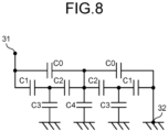
- FIG. 8 is a diagram for describing the voltage dividing capacitors 51, 52, 53, and 54 included in the vacuum circuit breaker 100 according to the first embodiment.
- FIG. 8 schematically illustrates current paths between the breaker unit terminal 31 and the breaker unit terminal 32, and electrostatic capacitances in the paths.
- Each of the electrostatic capacitances of the voltage dividing capacitor 53 and the voltage dividing capacitor 54 is defined as C0.
- Each of the electrostatic capacitances of the voltage dividing capacitors 52 provided in parallel with the vacuum valve 20C and the vacuum valve 20D is defined as C1.
- Each of the electrostatic capacitances of the dividing capacitors 51 provided in parallel with the vacuum valve 20A and the vacuum valve 20B is defined as C2.
- Each of the electrostatic capacitances C3 and C4 represents a floating capacitance with the ground, and is defined as an electrostatic capacitance that does not depend on an actual capacitor.
- the electrostatic capacitance C0 is 400 pF
- the electrostatic capacitance C1 is 800 pF
- the electrostatic capacitance C2 is 960 pF
- the electrostatic capacitance C3 is 120 pF
- the electrostatic capacitance C4 is 150 pF.
- a voltage applied between the breaker unit terminal 31 and the breaker unit terminal 32 is defined as 1 PU, for example, a voltage applied to the vacuum valve 20A is 0.21 PU, a voltage applied to the vacuum valve 20B is 0.22 PU, a voltage applied to the vacuum valve 20C is 0.35 PU, and a voltage applied to the vacuum valve 20D is 0.25 PU.
- the vacuum circuit breaker 100 includes, not only the voltage dividing capacitors 51 and 52 provided in parallel with the corresponding vacuum valves 20, but also the voltage dividing capacitor 53 connected between the vacuum valve 20B and the vacuum valve 20C and the voltage dividing capacitor 54 connected between the vacuum valve 20A and the vacuum valve 20D.
- the vacuum circuit breaker 100 can equalize voltages applied to vacuum valves 20 as compared with an example where the voltage dividing capacitors 53 and 54 are not provided.
- the insulation distance between the vacuum valves 20 can be shortened.
- the insulation distance is a spatial distance required for insulation between portions to which a voltage is applied.
- the insulation distance between the vacuum valve 20A and the vacuum valve 20B adjacent to each other in the Y axis direction can be shortened, so that the diameter of the tank 10 can be shortened. Since the diameter of the tank 10 of the vacuum circuit breaker 100 can be shortened, a compact configuration can be achieved.
- the number of vacuum valves 20 provided in the vacuum circuit breaker 100 is not limited to four. It is sufficient that the vacuum circuit breaker 100 includes a plurality of vacuum valves 20, and at least two vacuum valves 20 adjacent to each other in the direction intersecting the center axis N0. The vacuum circuit breaker 100 includes at least two vacuum valves 20 adjacent to each other in the direction intersecting the center axis N0, so that it is possible to acquire an effect that a compact configuration can be achieved.
- the configuration described in the above embodiment is an example of the contents of the present disclosure.
- the configuration of the embodiment can be combined with another known technique. A part of the configuration of the embodiment can be omitted or changed without departing from the gist of the present disclosure.
Landscapes
- Gas-Insulated Switchgears (AREA)
Abstract
Description
- The present disclosure relates to a vacuum circuit breaker including a plurality of vacuum valves.
- Conventionally, attempts have been made to increase the voltage of a vacuum circuit breaker in order to expand the application range. As one of the vacuum circuit breakers for achieving high voltage, a vacuum circuit breaker having a structure in which a plurality of breaking points are connected in series, that is, a so-called multi-point breaking structure, is known. Patent Literature 1 discloses a vacuum circuit breaker includes a plurality of vacuum valves connected in series with each other. The plurality of vacuum valves are disposed inside a tank.
- Patent Literature 1:
Japanese Patent Application Laid-open No. S58-194225 - According to the conventional technique disclosed in Patent Literature 1, the plurality of vacuum valves are disposed in one row on a center axis of the circular cylindrical tank. As the number of vacuum valves installed in the vacuum circuit breaker increases, the dimension of the vacuum circuit breaker in a direction of the center axis of the tank inevitably increases by the length of additional vacuum valves. Therefore, according to the conventional technique, the vacuum circuit breaker is significantly increased in size in the direction of the center axis of the tank. As a result, there has been a problem in which a compact configuration is difficult to be achieved.
- The present disclosure has been made in view of the above, and an object of the present disclosure is to obtain a vacuum circuit breaker that enables the achievement of a compact configuration.
- To solve the above problem and achieve an object, a vacuum circuit breaker according to the present disclosure, includes: a plurality of vacuum valves each of which includes: a vacuum container having a cylindrical shape; a fixed electrode fixed inside the vacuum container; a movable conductor protruding from an inside of the vacuum container to an outside of the vacuum container and movable in a direction of a center axis of the vacuum container; and a movable electrode to move together with the movable conductor inside the vacuum container to be capable of being separated from the fixed electrode and coming into contact with the fixed electrode, the plurality of vacuum valves being connected in series with each other; and a tank that has a cylindrical shape and accommodates the plurality of vacuum valves. The plurality of vacuum valves include at least two vacuum valves adjacent to each other in a direction intersecting a center axis of the tank.
- The vacuum circuit breaker according to the present disclosure can acquire an effect that a compact configuration can be achieved.
-
-
FIG. 1 is a diagram illustrating an external view of a vacuum circuit breaker according to a first embodiment. -
FIG. 2 is a first top view illustrating an internal configuration of a tank of the vacuum circuit breaker according to the first embodiment. -
FIG. 3 is a first side view illustrating the internal configuration of the tank of the vacuum circuit breaker according to the first embodiment. -
FIG. 4 is a second top view illustrating the internal configuration of the tank of the vacuum circuit breaker according to the first embodiment. -
FIG. 5 is a second side view illustrating the internal configuration of the tank of the vacuum circuit breaker according to the first embodiment. -
FIG. 6 is a first diagram for describing a current path when the vacuum circuit breaker according to the first embodiment performs a closing operation. -
FIG. 7 is a second diagram for describing a current path when the vacuum circuit breaker according to the first embodiment performs the closing operation. -
FIG. 8 is a diagram for describing voltage dividing capacitors included in the vacuum circuit breaker according to the first embodiment. - Hereinafter, a vacuum circuit breaker according to an embodiment will be described in detail with reference to the drawings.
-
FIG. 1 is a diagram illustrating an external view of avacuum circuit breaker 100 according to a first embodiment. Thevacuum circuit breaker 100 includes acylindrical tank 10, twobushings tank 10 in a vertical direction, anoperation device 13, twotubes 14 and 15 erected at lower portions of thetank 10 in the vertical direction, and twocurrent transformers tank 10 includes a circular cylinder made of a metal material and metal flanges that close ends of the circular cylinder. Thetank 10 is connected to a reference potential point. An insulating gas is enclosed inside thetank 10. Thetank 10 is supported by aframe 18 erected on an installation surface. Thecurrent transformer 16 is provided for thebushing 11. Thecurrent transformer 17 is provided for thebushing 12. An X axis, a Y axis, and a Z axis are three axes perpendicular to each other. The X axis and the Y axis are horizontal axes. The Z axis is a vertical axis. -
FIG. 2 is a first top view illustrating an internal configuration of thetank 10 of thevacuum circuit breaker 100 according to the first embodiment.FIG. 3 is a first side view illustrating the internal configuration of thetank 10 of thevacuum circuit breaker 100 according to the first embodiment.FIG. 4 is a second top view illustrating the internal configuration of thetank 10 of thevacuum circuit breaker 100 according to the first embodiment.FIG. 5 is a second side view illustrating the internal configuration of thetank 10 of thevacuum circuit breaker 100 according to the first embodiment. InFIGS. 2 to 5 , some of the constituent elements inside thetank 10 are illustrated in cross section. - The
vacuum circuit breaker 100 includes avacuum valve 20A that is a first vacuum valve, avacuum valve 20B that is a second vacuum valve, avacuum valve 20C that is a third vacuum valve, and avacuum valve 20D that is a fourth vacuum valve. In the following description, when not being distinguished from each other, the fourvacuum valves vacuum valve 20. Each of thevacuum valves 20 constitutes a breaker unit of thevacuum circuit breaker 100. - Each
vacuum valve 20 includes acylindrical vacuum container 21, afixed electrode 22 fixed inside thevacuum container 21, and amovable electrode 23 movable inside thevacuum container 21. Thefixed electrode 22 and themovable electrode 23 of eachvacuum valve 20 constitute a breaking point disposed inside thevacuum container 21. A center axis N0 of thetank 10 and the respective center axes N1, N2, N3, and N4 of thevacuum containers 21 are all parallel to the X axis. - In the following description, in each
vacuum valve 20, a state in which themovable electrode 23 is electrically connected to thefixed electrode 22 is referred to as a closed state, and a state in which the connection between thefixed electrode 22 and themovable electrode 23 is interrupted is referred to as an open state.FIGS. 2 and3 illustrate thevacuum circuit breaker 100 in the open state.FIGS. 4 and5 illustrate thevacuum circuit breaker 100 in the closed state. In the following description, an operation of thevacuum circuit breaker 100 when the state is changed from the open state to the closed state is referred to as a closing operation, and an operation of thevacuum circuit breaker 100 when the state is changed from the closed state to the open state is referred to as an opening operation. Thevacuum circuit breaker 100 closes an electric circuit by the closing operation, and opens the electric circuit by the opening operation. Furthermore, in eachvacuum valve 20, amovable electrode 23 side is referred to as a movable side with respect to thefixed electrode 22, and a side opposite to the movable side is referred to as a fixed side. - The
vacuum container 21 includes a circular cylinder made of an insulating material and metal flanges that close ends of the circular cylinder. The inside of thevacuum container 21 is maintained at a high vacuum. Afixed conductor 24 is disposed inside thevacuum container 21. Thefixed conductor 24 is disposed at a fixed side end of thevacuum container 21. The fixedelectrode 22 is fixed to a distal end of the fixedconductor 24. A bellows 26 is disposed at a movable side end of thevacuum container 21 inside thevacuum container 21. Amovable conductor 25 penetrates a movable side end of thevacuum container 21, and protrudes from the inside of thevacuum container 21 to the outside of thevacuum container 21. Themovable electrode 23 is fixed to a distal end of themovable conductor 25 inside thevacuum container 21. In eachvacuum valve 20, the fixedelectrode 22, themovable electrode 23, the fixedconductor 24, and themovable conductor 25 are disposed on the center axis of thevacuum container 21. - The
movable conductor 25 reciprocates in the direction of the center axis of thevacuum container 21. Themovable electrode 23 moves together with themovable conductor 25 inside thevacuum container 21. The bellows 26 expands and contracts, following the movement of themovable conductor 25. During the closing operation, themovable electrode 23 moves toward the fixed side, and comes into contact with the fixedelectrode 22. During the opening operation, themovable electrode 23 moves toward the movable side, and is separated from the fixedelectrode 22. Thevacuum circuit breaker 100 opens and closes the electric circuit by moving themovable electrode 23 inside eachvacuum valve 20. - Two
link mechanisms 27 are disposed inside thetank 10. Furthermore, twosupport bushings 30 are provided inside thetank 10. One of the twolink mechanisms 27 is connected between themovable conductor 25 of thevacuum valve 20A and themovable conductor 25 of thevacuum valve 20C. The other of the twolink mechanisms 27 is connected between themovable conductor 25 of thevacuum valve 20B and themovable conductor 25 of thevacuum valve 20D. Hereinafter, thelink mechanism 27 connected between themovable conductor 25 of thevacuum valve 20A and themovable conductor 25 of thevacuum valve 20C is referred to as a first link mechanism, and thelink mechanism 27 connected between themovable conductor 25 of thevacuum valve 20B and themovable conductor 25 of thevacuum valve 20D is referred to as a second link mechanism. Acontact pressure spring 37 for applying a contact pressure to the fixedelectrode 22 and themovable electrode 23 is provided between eachmovable conductor 25 and thelink mechanism 27. InFIGS. 3 and5 , illustrations of the contact pressure springs 37 are omitted. - The first link mechanism is accommodated in a
case 28. Thecase 28 of the first link mechanism is supported by a first support bushing that is one of the twosupport bushings 30. The first link mechanism moves themovable conductor 25 of thevacuum valve 20A and themovable conductor 25 of thevacuum valve 20C. - The second link mechanism is accommodated in a
case 28. Thecase 28 of the second link mechanism is supported by a second support bushing that is the other of the twosupport bushings 30. The second link mechanism moves themovable conductor 25 of thevacuum valve 20B and themovable conductor 25 of thevacuum valve 20D. - As illustrated in
FIGS. 3 and5 , thevacuum circuit breaker 100 includes two operatingrods 29. Each operatingrod 29 is made of an insulating material. A first operating rod that is one of the two operatingrods 29 is disposed so as to pass through the inside of the tube 14 and the inside of the first support bushing. One end of the first operating rod is connected to theoperation device 13. An opposite end of the first operating rod is connected to the first link mechanism. Theoperation device 13 operates themovable conductor 25 of thevacuum valve 20A and themovable conductor 25 of thevacuum valve 20C via the first operating rod and the first link mechanism. - A second operating rod that is the other of the two operating
rods 29 is disposed so as to pass through the inside of thetube 15 and the inside of the second support bushing. One end of the second operating rod is connected to theoperation device 13. An opposite end of the second operating rod is connected to the second link mechanism. Theoperation device 13 operates themovable conductor 25 of thevacuum valve 20B and themovable conductor 25 of thevacuum valve 20D via the second operating rod and the second link mechanism. Thevacuum circuit breaker 100 performs the closing operation and the opening operation by operating themovable conductors 25 of therespective vacuum valves 20 by theoperation device 13. - The fixed side end of the fixed
conductor 24 of thevacuum valve 20A is connected to aconnection point 34. The fixed side end of the fixedconductor 24 of thevacuum valve 20B is connected to aconnection point 33. Aninternal conductor 35 electrically connects theconnection point 33 and theconnection point 34. - The fixed side end of the fixed
conductor 24 of thevacuum valve 20C is connected to abreaker unit terminal 31 that is a first terminal. Thebreaker unit terminal 31 is one terminal of the breaker unit constituted of the fourvacuum valves 20. Thevacuum valve 20C and thelink mechanism 27 that is the first link mechanism are connected between thebreaker unit terminal 31 and thevacuum valve 20A. - The solid side end of the fixed
conductor 24 of thevacuum valve 20D is connected to abreaker unit terminal 32 that is a second terminal. Thebreaker unit terminal 32 is the other terminal of the breaker unit constituted of the fourvacuum valves 20. Thevacuum valve 20D and thelink mechanism 27 that is the second link mechanism are connected between thebreaker unit terminal 32 and thevacuum valve 20B. - As illustrated in
FIGS. 3 and5 , thevacuum circuit breaker 100 includes twoexternal conductors 36. Eachexternal conductor 36 protrudes from thetank 10. A first external conductor that is one of the twoexternal conductors 36 is disposed so as to pass through the inside of thebushing 11 illustrated inFIG. 1 . Thecurrent transformer 16 illustrated inFIG. 1 detects a current flowing through the first external conductor. A second external conductor that is the other of the twoexternal conductors 36 is disposed so as to pass through the inside of thebushing 12 illustrated inFIG. 1 . Thecurrent transformer 17 illustrated inFIG. 1 detects a current flowing through the second external conductor. An end of the first external conductor on the vertically lower side is connected to thebreaker unit terminal 31. An end of the second external conductor on the vertically lower side is connected to thebreaker unit terminal 32. - The
vacuum circuit breaker 100 includes tworesistors contact 41 and amovable contact 42 constituting a first opening/closing unit, a fixedcontact 46 and amovable contact 47 constituting a second opening/closing unit, and twolink mechanisms resistor 40 that is a first resistor is connected to thebreaker unit terminal 31. Theresistor 45 that is a second resistor is connected to thebreaker unit terminal 32. Theresistors vacuum valve 20. The first opening/closing unit and the second opening/closing unit are opening/closing units that open and close a circuit including theresistor 40 and theresistor 45. - The fixed
contact 41 is connected to theresistor 40. Themovable contact 42 is connected to thelink mechanism 43. Thelink mechanism 43 is connected to thelink mechanism 27 that is the first link mechanism. Thelink mechanism 43 is accommodated in acase 44. Thecase 44 is connected to theconnection point 33. Thelink mechanism 43 operates in conjunction with the first link mechanism, so that themovable contact 42 reciprocates in the direction of the center axis N0. The movement of themovable contact 42 changes the state of the first opening/closing unit between a state in which a distal end of themovable contact 42 is in contact with a distal end of the fixedcontact 41 and a state in which the distal end of themovable contact 42 is separated from the distal end of the fixedcontact 41. - The fixed
contact 46 is connected to theresistor 45. Themovable contact 47 is connected to thelink mechanism 48. Thelink mechanism 48 is connected to thelink mechanism 27 that is the second link mechanism. Thelink mechanism 48 is accommodated in acase 49. Thecase 49 is connected to theconnection point 34. Thelink mechanism 48 operates in conjunction with the second link mechanism, so that themovable contact 47 reciprocates in the direction of the center axis N0. The movement of themovable contact 47 changes the state of the second opening/closing unit between a state in which a distal end of themovable contact 47 is in contact with a distal end of the fixedcontact 46 and a state in which the distal end of themovable contact 47 is separated from the distal end of the fixedcontact 46. - The
vacuum circuit breaker 100 includes first voltage dividing capacitors provided in parallel with the respective fourvacuum valves 20, a second voltage dividing capacitor, and a third voltage dividing capacitor. The first voltage dividing capacitors includevoltage dividing capacitors 51 provided in parallel with thevacuum valve 20A,voltage dividing capacitors 51 provided in parallel with thevacuum valve 20B,voltage dividing capacitors 52 provided in parallel with thevacuum valve 20C, andvoltage dividing capacitors 52 provided in parallel with thevacuum valve 20D. - The
vacuum valve 20A is provided with an arbitrary number ofvoltage dividing capacitors 51.FIGS. 3 and5 illustrate two of a plurality ofvoltage dividing capacitors 51 provided for thevacuum valve 20A. Thevacuum valve 20B is provided with an arbitrary number ofvoltage dividing capacitors 51. InFIGS. 3 and5 , thevacuum valve 20B and thevoltage dividing capacitors 51 provided for thevacuum valve 20B are disposed in the back of thevacuum valves - The
vacuum valve 20C is provided with an arbitrary number ofvoltage dividing capacitors 52.FIGS. 3 and5 illustrate two of a plurality ofvoltage dividing capacitors 52 provided for thevacuum valve 20C. Thevacuum valve 20D is provided with an arbitrary number ofvoltage dividing capacitors 52. InFIGS. 3 and5 , thevacuum valve 20D and thevoltage dividing capacitors 52 provided for thevacuum valve 20D are disposed in the back of thevacuum valves - A
voltage dividing capacitor 53 that is the second voltage dividing capacitor is provided in parallel with the fixedcontact 41 and themovable contact 42 that are the first opening/closing unit and thecase 44. Avoltage dividing capacitor 54 that is the third voltage dividing capacitor is provided in parallel with the fixedcontact 46 and themovable contact 47 that are the second opening/closing unit and thecase 49. Thevacuum circuit breaker 100 is provided with one or a plurality ofvoltage dividing capacitors 53 and one or a plurality ofvoltage dividing capacitors 54.FIGS. 3 and5 illustrate a mode in which onevoltage dividing capacitor 53 and onevoltage dividing capacitor 54 are provided. - Next, a first feature of the
vacuum circuit breaker 100 according to the first embodiment will be described. The fourvacuum valves 20 of thevacuum circuit breaker 100 are connected in series with each other. From among the fourvacuum valves 20, thevacuum valve 20A and thevacuum valve 20B are adjacent to each other in the Y axis direction that is a direction intersecting the center axis N0 of thetank 10. Thevacuum valve 20A and thevacuum valve 20B are connected in series with theinternal conductor 35 interposed therebetween. Thevacuum valve 20A and thevacuum valve 20C are adjacent to each other with thelink mechanism 27 interposed therebetween in the direction of the center axis N0. Thevacuum valve 20B and thevacuum valve 20D are adjacent to each other with thelink mechanism 27 interposed therebetween in the direction of the center axis N0. - The center axis N1 of the
vacuum valve 20A is shifted from the center axis N0 toward a first direction. The first direction is a direction of an arrow representing the Y axis inFIGS. 2 to 5 . The center axis N2 of thevacuum valve 20B is shifted from the center axis N0 toward a second direction. The second direction is a direction opposite to the first direction. In this manner, the position of thevacuum valve 20A and the position of thevacuum valve 20B are displaced in opposite directions from each other with respect to the center axis N0. - The
vacuum valve 20A and thevacuum valve 20B are adjacent to each other in the Y axis direction, so that the dimension of thevacuum circuit breaker 100 in the direction of the center axis N0 can be shortened as compared with an example where all the fourvacuum valves 20 are arranged in the direction of the center axis N0. Therefore, an increase in the dimension of thevacuum circuit breaker 100 in the direction of the center axis N0 can be reduced, and a compact configuration can be achieved. - Next, a second feature of the
vacuum circuit breaker 100 according to the first embodiment will be described. The fixedcontact 41 and themovable contact 42 that constitute the first opening/closing unit are adjacent to thevacuum valve 20B with thelink mechanism 43 interposed therebetween in the direction of the center axis N0. Furthermore, the fixedcontact 41 and themovable contact 42 are adjacent to thevacuum valve 20C in the Y axis direction. The fixedcontact 46 and themovable contact 47 that constitute the second opening/closing unit are adjacent to thevacuum valve 20A with thelink mechanism 48 interposed therebetween in the direction of the center axis N0. Furthermore, the fixedcontact 46 and themovable contact 47 are adjacent to thevacuum valve 20D in the Y axis direction. Theresistor 40 and the first opening/closing unit are attached to two breaking points of thevacuum valve 20A and thevacuum valve 20C. Theresistor 45 and the second opening/closing unit are attached to two breaking points of thevacuum valve 20B and thevacuum valve 20D. -
FIG. 6 is a first diagram for describing a current path when thevacuum circuit breaker 100 according to the first embodiment performs the closing operation. When thevacuum circuit breaker 100 performs the closing operation, the first opening/closing unit and the second opening/closing unit are closed before the breaking points of therespective vacuum valves 20 are closed. A bold line with a dotted tone illustrated inFIG. 6 represents the current path when the first opening/closing unit and the second opening/closing unit are closed. - The
operation device 13 operates themovable contact 42 via the operatingrod 29 and thelink mechanisms movable contact 42 comes into contact with the fixedcontact 41 before themovable electrodes 23 come into contact with the fixedelectrodes 22 in thevacuum valves operation device 13 operates themovable contact 47 via the operatingrod 29 and thelink mechanisms movable contact 47 comes into contact with the fixedcontact 46 before themovable electrodes 23 come into contact with the fixedelectrodes 22 in thevacuum valves respective vacuum valves 20 are closed. When the first opening/closing unit and the second opening/closing unit are closed, a path passing through theresistors internal conductor 35 is formed between thebreaker unit terminal 31 and thebreaker unit terminal 32. A current flows through such a path. -
FIG. 7 is a second diagram for describing a current path when thevacuum circuit breaker 100 according to the first embodiment performs the closing operation. A bold line with a dotted tone illustrated inFIG. 7 represents a current path when the breaking points of therespective vacuum valves 20 are closed after the first opening/closing unit and the second opening/closing unit are closed. - After the
movable contact 42 comes into contact with the fixedcontact 41 and themovable contact 47 comes into contact with the fixedcontact 46, themovable electrodes 23 come into contact with the fixedelectrodes 22 in therespective vacuum valves 20. As a result, as illustrated inFIG. 7 , a current path passing through each of thevacuum valves 20 and theinternal conductor 35 is formed between thebreaker unit terminal 31 and thebreaker unit terminal 32. The resistance of the path illustrated inFIG. 7 is lower than the resistance of the path illustrated inFIG. 6 , so that a current flows through the path illustrated inFIG. 7 . - As illustrated in
FIG. 6 , when a current flows through the path including theresistors breaker unit terminal 31 and thebreaker unit terminal 32 is reduced by theresistors FIG. 6 , flows through the path illustrated inFIG. 7 when the breaking points of therespective vacuum valves 20 are closed. As a result, thevacuum circuit breaker 100 can reduce the inrush current when the electric circuit is connected. Thevacuum circuit breaker 100 can reduce the load on the entire power system including thevacuum circuit breaker 100 by reducing the inrush current. Furthermore, thevacuum circuit breaker 100 can reduce the load experienced by the constituent elements of thevacuum circuit breaker 100 by reducing the inrush current. - Since the
vacuum valve 20A and thevacuum valve 20B are arranged in the Y axis direction, a space where novacuum valve 20 is disposed is created on a side opposite to thevacuum valve 20C as viewed from thevacuum valve 20A. The fixedcontact 46 and themovable contact 47 are disposed by utilizing such a space. Furthermore, a space where novacuum valve 20 is disposed is created on a side opposite to thevacuum valve 20D as viewed from thevacuum valve 20B. The fixedcontact 41 and themovable contact 42 are disposed by utilizing such a space. Thus, in thevacuum circuit breaker 100, the fixedcontacts movable contacts tank 10, and a compact configuration can be achieved. Furthermore, in thevacuum circuit breaker 100, one opening/closing unit is provided for twovacuum valves 20. Therefore, the number of parts can be reduced as compared with an example where one opening/closing unit is provided for eachvacuum valve 20. As a result, thevacuum circuit breaker 100 can reduce the inrush current with a simple configuration. - Next, a third feature of the
vacuum circuit breaker 100 according to the first embodiment will be described. Thevacuum circuit breaker 100 includes, in addition to thevoltage dividing capacitors vacuum valves 20, thevoltage dividing capacitor 53 provided in parallel with the fixedcontact 41 and themovable contact 42 and thevoltage dividing capacitor 54 provided in parallel with the fixedcontact 46 and themovable contact 47. Thevoltage dividing capacitor 53 is connected between thevacuum valve 20B and thevacuum valve 20C. Thevoltage dividing capacitor 54 is connected between thevacuum valve 20A and thevacuum valve 20D. -
FIG. 8 is a diagram for describing thevoltage dividing capacitors vacuum circuit breaker 100 according to the first embodiment.FIG. 8 schematically illustrates current paths between thebreaker unit terminal 31 and thebreaker unit terminal 32, and electrostatic capacitances in the paths. - Each of the electrostatic capacitances of the
voltage dividing capacitor 53 and thevoltage dividing capacitor 54 is defined as C0. Each of the electrostatic capacitances of thevoltage dividing capacitors 52 provided in parallel with thevacuum valve 20C and thevacuum valve 20D is defined as C1. Each of the electrostatic capacitances of the dividingcapacitors 51 provided in parallel with thevacuum valve 20A and thevacuum valve 20B is defined as C2. Each of the electrostatic capacitances C3 and C4 represents a floating capacitance with the ground, and is defined as an electrostatic capacitance that does not depend on an actual capacitor. For example, the electrostatic capacitance C0 is 400 pF, the electrostatic capacitance C1 is 800 pF, the electrostatic capacitance C2 is 960 pF, the electrostatic capacitance C3 is 120 pF, and the electrostatic capacitance C4 is 150 pF. - In this case, when a voltage applied between the
breaker unit terminal 31 and thebreaker unit terminal 32 is defined as 1 PU, for example, a voltage applied to thevacuum valve 20A is 0.21 PU, a voltage applied to thevacuum valve 20B is 0.22 PU, a voltage applied to thevacuum valve 20C is 0.35 PU, and a voltage applied to thevacuum valve 20D is 0.25 PU. - The
vacuum circuit breaker 100 includes, not only thevoltage dividing capacitors vacuum valves 20, but also thevoltage dividing capacitor 53 connected between thevacuum valve 20B and thevacuum valve 20C and thevoltage dividing capacitor 54 connected between thevacuum valve 20A and thevacuum valve 20D. Thevacuum circuit breaker 100 can equalize voltages applied tovacuum valves 20 as compared with an example where thevoltage dividing capacitors - Since the voltages applied to the
vacuum valves 20 can be equalized, the insulation distance between thevacuum valves 20 can be shortened. The insulation distance is a spatial distance required for insulation between portions to which a voltage is applied. The insulation distance between thevacuum valve 20A and thevacuum valve 20B adjacent to each other in the Y axis direction can be shortened, so that the diameter of thetank 10 can be shortened. Since the diameter of thetank 10 of thevacuum circuit breaker 100 can be shortened, a compact configuration can be achieved. - Note that the number of
vacuum valves 20 provided in thevacuum circuit breaker 100 is not limited to four. It is sufficient that thevacuum circuit breaker 100 includes a plurality ofvacuum valves 20, and at least twovacuum valves 20 adjacent to each other in the direction intersecting the center axis N0. Thevacuum circuit breaker 100 includes at least twovacuum valves 20 adjacent to each other in the direction intersecting the center axis N0, so that it is possible to acquire an effect that a compact configuration can be achieved. - The configuration described in the above embodiment is an example of the contents of the present disclosure. The configuration of the embodiment can be combined with another known technique. A part of the configuration of the embodiment can be omitted or changed without departing from the gist of the present disclosure.
- 10 tank; 11, 12 bushing; 13 operation device; 14, 15 tube; 16, 17 current transformer; 18 frame; 20, 20A, 20B, 20C, 20D vacuum valve; 21 vacuum container; 22 fixed electrode; 23 movable electrode; 24 fixed conductor; 25 movable conductor; 26 bellows; 27, 43, 48 link mechanism; 28, 44, 49 case; 29 operating rod; 30 support bushing; 31, 32 breaker unit terminal; 33, 34 connection point; 35 internal conductor; 36 external conductor; 37 contact pressure spring; 40, 45 resistor; 41, 46 fixed contact; 42, 47 movable contact; 51, 52, 53, 54 voltage dividing capacitor; 100 vacuum circuit breaker; N0, N1, N2, N3, N4 center axis.
Claims (6)
- A vacuum circuit breaker, comprising:a plurality of vacuum valves each of which includes: a vacuum container having a cylindrical shape; a fixed electrode fixed inside the vacuum container; a movable conductor protruding from an inside of the vacuum container to an outside of the vacuum container and movable in a direction of a center axis of the vacuum container; and a movable electrode to move together with the movable conductor inside the vacuum container to be capable of being separated from the fixed electrode and coming into contact with the fixed electrode, the plurality of vacuum valves being connected in series with each other; anda tank that has a cylindrical shape and accommodates the plurality of vacuum valves, whereinthe plurality of vacuum valves include at least two vacuum valves adjacent to each other in a direction intersecting a center axis of the tank.
- The vacuum circuit breaker according to claim 1, whereinthe plurality of vacuum valves include a first vacuum valve and a second vacuum valve adjacent to each other in the direction intersecting the center axis of the tank and connected in series with each other,a center axis of the vacuum container included in the first vacuum valve is shifted from the center axis of the tank toward a first direction, anda center axis of the vacuum container included in the second vacuum valve is shifted from the center axis of the tank toward a second direction opposite to the first direction.
- The vacuum circuit breaker according to claim 2, comprising:a first external conductor protruding from the tank and connected to a first terminal that is one terminal of a breaker unit constituted of the plurality of vacuum valves; anda second external conductor protruding from the tank and connected to a second terminal that is another terminal of the breaker unit, whereinthe plurality of vacuum valves include:a third vacuum valve connected between the first vacuum valve and the first terminal; anda fourth vacuum valve connected between the second vacuum valve and the second terminal.
- The vacuum circuit breaker according to claim 3, comprising:a first link mechanism connected between the movable conductor of the first vacuum valve and the movable conductor of the third vacuum valve, the first link mechanism to move the movable conductor of the first vacuum valve and the movable conductor of the third vacuum valve; anda second link mechanism connected between the movable conductor of the second vacuum valve and the movable conductor of the fourth vacuum valve, the second link mechanism to move the movable conductor of the second vacuum valve and the movable conductor of the fourth vacuum valve.
- The vacuum circuit breaker according to claim 3 or 4, comprising:a first resistor connected to the first terminal;a second resistor connected to the second terminal; andan opening/closing unit to open and close a circuit including the first resistor and the second resistor,wherein
the opening/closing unit includes:a first opening/closing unit adjacent to the second vacuum valve in a direction of the center axis of the tank and adjacent to the third vacuum valve in the direction intersecting the center axis of the tank; anda second opening/closing unit adjacent to the first vacuum valve in the direction of the center axis of the tank and adjacent to the fourth vacuum valve in the direction intersecting the center axis of the tank. - The vacuum circuit breaker according to any one of claims 3 to 5, comprising:a first voltage dividing capacitor provided in parallel with each of the plurality of vacuum valves;a second voltage dividing capacitor connected between the second vacuum valve and the third vacuum valve; anda third voltage dividing capacitor connected between the first vacuum valve and the fourth vacuum valve.
Applications Claiming Priority (1)
| Application Number | Priority Date | Filing Date | Title |
|---|---|---|---|
| PCT/JP2021/027312 WO2023002598A1 (en) | 2021-07-21 | 2021-07-21 | Vacuum circuit breaker |
Publications (2)
| Publication Number | Publication Date |
|---|---|
| EP4376041A1 true EP4376041A1 (en) | 2024-05-29 |
| EP4376041A4 EP4376041A4 (en) | 2024-08-14 |
Family
ID=80912414
Family Applications (1)
| Application Number | Title | Priority Date | Filing Date |
|---|---|---|---|
| EP21950948.6A Pending EP4376041A4 (en) | 2021-07-21 | 2021-07-21 | VACUUM CIRCUIT BREAKER |
Country Status (4)
| Country | Link |
|---|---|
| US (1) | US20240234057A1 (en) |
| EP (1) | EP4376041A4 (en) |
| JP (1) | JP7019115B1 (en) |
| WO (1) | WO2023002598A1 (en) |
Families Citing this family (1)
| Publication number | Priority date | Publication date | Assignee | Title |
|---|---|---|---|---|
| DE102023209613A1 (en) * | 2023-09-29 | 2025-04-03 | Siemens Energy Global GmbH & Co. KG | Arrangement of vacuum interrupters for switching high voltages |
Family Cites Families (12)
| Publication number | Priority date | Publication date | Assignee | Title |
|---|---|---|---|---|
| FR1395289A (en) * | 1963-05-14 | 1965-07-21 | Ass Elect Ind | Improvements to high voltage switchgear |
| US3300609A (en) * | 1963-05-15 | 1967-01-24 | Ass Elect Ind | Switchgear for high voltage power circuits with removable vacuum switch units |
| US4489291A (en) * | 1981-10-12 | 1984-12-18 | Tokyo Shibaura Denki Kabushiki Kaisha | Circuit breaker provided with parallel resistor |
| JPS58194225A (en) * | 1982-05-10 | 1983-11-12 | 株式会社東芝 | Breaker |
| US5245145A (en) * | 1991-07-23 | 1993-09-14 | Abb Power T&D Company Inc. | Modular closing resistor |
| JP3175976B2 (en) * | 1992-06-18 | 2001-06-11 | 株式会社東芝 | Circuit breaker with resistance |
| JPH07320611A (en) * | 1994-05-23 | 1995-12-08 | Hitachi Ltd | Gas insulated switchgear |
| JP2001312948A (en) * | 2000-04-28 | 2001-11-09 | Toshiba Corp | Switchgear |
| DE502007004867D1 (en) * | 2007-09-10 | 2010-10-07 | Abb Technology Ag | On resistance for high voltage circuit breaker |
| CN101855694B (en) * | 2007-09-10 | 2014-04-23 | Abb技术有限公司 | High voltage power switch with switch for access to closing resistor |
| JP6093936B2 (en) * | 2013-08-08 | 2017-03-15 | 株式会社日立産機システム | Vacuum valve for vacuum switch gear |
| JP6156535B1 (en) * | 2016-03-17 | 2017-07-05 | 株式会社明電舎 | Voltage divider capacitor |
-
2021
- 2021-07-21 US US18/560,235 patent/US20240234057A1/en active Pending
- 2021-07-21 WO PCT/JP2021/027312 patent/WO2023002598A1/en not_active Ceased
- 2021-07-21 JP JP2021568182A patent/JP7019115B1/en active Active
- 2021-07-21 EP EP21950948.6A patent/EP4376041A4/en active Pending
Also Published As
| Publication number | Publication date |
|---|---|
| WO2023002598A1 (en) | 2023-01-26 |
| EP4376041A4 (en) | 2024-08-14 |
| JP7019115B1 (en) | 2022-02-14 |
| US20240234057A1 (en) | 2024-07-11 |
| JPWO2023002598A1 (en) | 2023-01-26 |
Similar Documents
| Publication | Publication Date | Title |
|---|---|---|
| US10957505B2 (en) | Disconnect switch assemblies with a shared actuator that concurrently applies motive forces in opposing directions and related circuit breakers and methods | |
| US11710611B2 (en) | Circuit breaker | |
| US20120256711A1 (en) | Switch having two sets of contact elements and two drives | |
| CN106165046B (en) | Compound shutter | |
| CN1170948A (en) | Circuit breaker | |
| EP4376041A1 (en) | Vacuum circuit breaker | |
| US3792213A (en) | High-voltage circuit interrupter incorporating series vacuum interrupter elements | |
| US3418439A (en) | High-voltage electric circuit breaker | |
| US2981814A (en) | Circuit interrupters | |
| US10038312B2 (en) | High-voltage combined electrical apparatus | |
| US3725623A (en) | Gas-blast downstream-type of high-voltage circuit breaker having field-controlling shields and single venting movable contact | |
| JP2006019193A (en) | Switchgear | |
| US6995330B2 (en) | Earthing switch | |
| JP7608296B2 (en) | Gas insulated switchgear | |
| JP7028270B2 (en) | Vacuum interrupters and vacuum circuit breakers | |
| US20150114933A1 (en) | Pushrod assembly for a medium voltage vacuum circuit breaker | |
| US5457294A (en) | UHV breaker provided with resistances | |
| CN110416020B (en) | Switching device | |
| JP7790623B1 (en) | Vacuum circuit breaker | |
| US4239948A (en) | Grounded support tank type gas circuit breaker | |
| CN109416993A (en) | Switch with arc-control device | |
| US3259725A (en) | Electric circuit breaker having a modular arrangement of interrupting assemblies | |
| EP3906574B1 (en) | Circuit breaker having internal transient recovery voltage capacitor assembly | |
| KR102696959B1 (en) | Vaccum interrupter and vaccum circuit breaker having the same | |
| JP7346711B2 (en) | Switchgear with two disconnector units connected in series |
Legal Events
| Date | Code | Title | Description |
|---|---|---|---|
| STAA | Information on the status of an ep patent application or granted ep patent |
Free format text: STATUS: THE INTERNATIONAL PUBLICATION HAS BEEN MADE |
|
| PUAI | Public reference made under article 153(3) epc to a published international application that has entered the european phase |
Free format text: ORIGINAL CODE: 0009012 |
|
| STAA | Information on the status of an ep patent application or granted ep patent |
Free format text: STATUS: REQUEST FOR EXAMINATION WAS MADE |
|
| 17P | Request for examination filed |
Effective date: 20231220 |
|
| AK | Designated contracting states |
Kind code of ref document: A1 Designated state(s): AL AT BE BG CH CY CZ DE DK EE ES FI FR GB GR HR HU IE IS IT LI LT LU LV MC MK MT NL NO PL PT RO RS SE SI SK SM TR |
|
| A4 | Supplementary search report drawn up and despatched |
Effective date: 20240712 |
|
| RIC1 | Information provided on ipc code assigned before grant |
Ipc: H01H 33/666 20060101ALI20240708BHEP Ipc: H01H 33/16 20060101ALI20240708BHEP Ipc: H01H 33/14 20060101ALI20240708BHEP Ipc: H01H 33/66 20060101AFI20240708BHEP |
|
| DAV | Request for validation of the european patent (deleted) | ||
| DAX | Request for extension of the european patent (deleted) |