EP4375915A1 - Material design assistance device, material design assistance method, and program - Google Patents
Material design assistance device, material design assistance method, and program Download PDFInfo
- Publication number
- EP4375915A1 EP4375915A1 EP22845885.7A EP22845885A EP4375915A1 EP 4375915 A1 EP4375915 A1 EP 4375915A1 EP 22845885 A EP22845885 A EP 22845885A EP 4375915 A1 EP4375915 A1 EP 4375915A1
- Authority
- EP
- European Patent Office
- Prior art keywords
- range
- exhaustive
- design condition
- design
- prediction
- Prior art date
- Legal status (The legal status is an assumption and is not a legal conclusion. Google has not performed a legal analysis and makes no representation as to the accuracy of the status listed.)
- Pending
Links
Images











Classifications
-
- G—PHYSICS
- G06—COMPUTING OR CALCULATING; COUNTING
- G06F—ELECTRIC DIGITAL DATA PROCESSING
- G06F30/00—Computer-aided design [CAD]
- G06F30/20—Design optimisation, verification or simulation
- G06F30/27—Design optimisation, verification or simulation using machine learning, e.g. artificial intelligence, neural networks, support vector machines [SVM] or training a model
-
- G—PHYSICS
- G05—CONTROLLING; REGULATING
- G05B—CONTROL OR REGULATING SYSTEMS IN GENERAL; FUNCTIONAL ELEMENTS OF SUCH SYSTEMS; MONITORING OR TESTING ARRANGEMENTS FOR SUCH SYSTEMS OR ELEMENTS
- G05B19/00—Program-control systems
- G05B19/02—Program-control systems electric
- G05B19/18—Numerical control [NC], i.e. automatically operating machines, in particular machine tools, e.g. in a manufacturing environment, so as to execute positioning, movement or co-ordinated operations by means of program data in numerical form
- G05B19/4097—Numerical control [NC], i.e. automatically operating machines, in particular machine tools, e.g. in a manufacturing environment, so as to execute positioning, movement or co-ordinated operations by means of program data in numerical form characterised by using design data to control NC machines, e.g. CAD/CAM
-
- G—PHYSICS
- G06—COMPUTING OR CALCULATING; COUNTING
- G06Q—INFORMATION AND COMMUNICATION TECHNOLOGY [ICT] SPECIALLY ADAPTED FOR ADMINISTRATIVE, COMMERCIAL, FINANCIAL, MANAGERIAL OR SUPERVISORY PURPOSES; SYSTEMS OR METHODS SPECIALLY ADAPTED FOR ADMINISTRATIVE, COMMERCIAL, FINANCIAL, MANAGERIAL OR SUPERVISORY PURPOSES, NOT OTHERWISE PROVIDED FOR
- G06Q50/00—Information and communication technology [ICT] specially adapted for implementation of business processes of specific business sectors, e.g. utilities or tourism
- G06Q50/04—Manufacturing
-
- G—PHYSICS
- G05—CONTROLLING; REGULATING
- G05B—CONTROL OR REGULATING SYSTEMS IN GENERAL; FUNCTIONAL ELEMENTS OF SUCH SYSTEMS; MONITORING OR TESTING ARRANGEMENTS FOR SUCH SYSTEMS OR ELEMENTS
- G05B2219/00—Program-control systems
- G05B2219/30—Nc systems
- G05B2219/45—Nc applications
- G05B2219/45234—Thin flat workpiece, sheet metal machining
-
- G—PHYSICS
- G06—COMPUTING OR CALCULATING; COUNTING
- G06F—ELECTRIC DIGITAL DATA PROCESSING
- G06F2111/00—Details relating to CAD techniques
- G06F2111/04—Constraint-based CAD
-
- G—PHYSICS
- G06—COMPUTING OR CALCULATING; COUNTING
- G06F—ELECTRIC DIGITAL DATA PROCESSING
- G06F2113/00—Details relating to the application field
- G06F2113/26—Composites
-
- G—PHYSICS
- G06—COMPUTING OR CALCULATING; COUNTING
- G06F—ELECTRIC DIGITAL DATA PROCESSING
- G06F2119/00—Details relating to the type or aim of the analysis or the optimisation
- G06F2119/14—Force analysis or force optimisation, e.g. static or dynamic forces
-
- G—PHYSICS
- G06—COMPUTING OR CALCULATING; COUNTING
- G06F—ELECTRIC DIGITAL DATA PROCESSING
- G06F2119/00—Details relating to the type or aim of the analysis or the optimisation
- G06F2119/18—Manufacturability analysis or optimisation for manufacturability
Definitions
- the present disclosure relates to a material design support apparatus, a material design support method, and a program.
- component compositions of elements in metals and production conditions are determined empirically or by trial and error.
- a design support method which includes: a search step of inputting a desired characteristic value in a database that is generated by using at least one mathematical model in which input information including a component composition of elements in metals and a production condition, and output information including a characteristic value of a metallic material, are related, and stores output data of the mathematical model in relation to input data for each mesh in which a range of inputs corresponding to the input information is separated by a plurality of sections, and retrieving a component composition of elements in metals and a production condition; and a presentation step of presenting the component composition of the elements in metals and the production condition corresponding to the desired characteristic value retrieved by the search step.
- Patent Document 1 Japanese Patent No. 6617842
- One object of the present disclosure is to provide a material design support device, a material design support method, and a program for supporting efficient optimization of design conditions for materials.
- the present disclosure includes the following configurations.
- FIG. 1 is a configuration diagram illustrating an example of a material design support system according to one embodiment.
- a material design support system 1 of FIG. 1 includes a material design support apparatus 10 and a user terminal 12.
- the material design support apparatus 10 and the user terminal 12 are connected via a communication network 18, such as a local area network (LAN), the Internet, or the like, and are communicable with each other to perform data communication.
- LAN local area network
- the Internet the like
- the user terminal 12 is an information processing terminal such as a PC, a tablet terminal, a smartphone, or the like, operated by a user such as a material designer.
- the user terminal 12 receives an input operation or a change operation of information necessary for optimizing a design condition for a material from the user, and causes the material design support apparatus 10 to execute the processing for supporting the optimization of the design condition for the material.
- the user terminal 12 receives the result of the processing for supporting the optimization of the design condition for the material executed by the material design support apparatus 10, and displays the result on a display device for checking by the user, for example.
- the material design support apparatus 10 is an information processing apparatus such as a PC for executing the processing for supporting the optimization of the design condition for the material.
- the material design support apparatus 10 executes the processing for supporting the optimization of the design condition for the material using a trained model in which a correspondence between a design condition for a material and a characteristic value of the material is learned.
- the material design support apparatus 10 transmits the result of the executed processing for supporting the optimization of the design condition for the material to the user terminal 12.
- the material design support system 1 illustrated in FIG. 1 is an example, and there are various system configuration examples depending on the application and purpose.
- the material design support apparatus 10 may be implemented by a plurality of computers or may be implemented as a cloud computing service.
- the material design support system 1 illustrated in FIG. 1 may be implemented by a stand-alone computer.
- the material design support apparatus 10 and the user terminal 12 illustrated in FIG. 1 are implemented in a computer 500 having a hardware configuration illustrated in FIG. 2 , for example.
- FIG. 2 is a hardware configuration diagram illustrating an example of the computer according to the one embodiment.
- the computer 500 of FIG. 2 includes an input device 501, a display device 502, an external I/F 503, a RAM 504, a ROM 505, a CPU 506, a communication I/F 507, a HDD 508, or the like, which are connected to each other via a bus B.
- the input device 501 and the display device 502 may be connected and used.
- the input device 501 is a touchscreen panel, operation keys or buttons, a keyboard, a mouse, or the like used by the user to input various signals.
- the display device 502 includes a display, such as a liquid crystal display, an organic EL display, or the like for displaying a screen, a speaker for outputting sound data, such as voice, sound, or the like, and the like.
- the communication I/F 507 is an interface used by the computer 500 to perform the data communication.
- the HDD 508 is an example of a non-volatile storage device that stores programs and data.
- the stored programs and data include an operating system (OS) that is basic software for controlling the entire computer 500, applications for providing various functions on the OS, or the like.
- OS operating system
- the computer 500 may use a drive device (for example, a solid state drive (SSD) or the like) using a flash memory as a storage media, in place of the HDD 508.
- SSD solid state drive
- the external I/F 503 is an interface provided with respect to an external device.
- Examples of the external device include a recording medium 503a or the like.
- the computer 500 can read from and/or write to the recording medium 503a via the external I/F 503.
- Examples of the recording medium 503a include a flexible disk, a CD, a DVD, an SD memory card, a USB memory, or the like.
- the ROM 505 is an example of a non-volatile semiconductor memory (storage device) that can retain programs and data even when the power is turned off.
- the ROM 505 stores programs and data, such as a BIOS that is executed when the computer 500 is started, OS settings, network settings, or the like.
- the RAM 504 is an example of a volatile semiconductor memory (storage device) that temporarily stores the programs and data.
- the CPU 506 is an arithmetic unit that reads the programs and data from a storage device, such as the ROM 505, the HDD 508, or the like into the RAM 504, and executes processing to control the entire computer 500 or implement functions thereof.
- the computer 500 according to the one embodiment implements various functions of the material design support apparatus 10 and of the user terminal 12, which will be described later, by executing programs.
- FIG. 3 is a functional configuration diagram illustrating an example of the material design support system according to the present embodiment.
- the material for which optimization of the design condition is supported is called a design target material.
- the design target material is, for example, an aluminum alloy.
- the material design support apparatus 10 of the material design support system 1 illustrated in FIG. 3 includes a design condition setting unit 30, a required characteristic setting unit 32, an exhaustive prediction point generation unit 34, a prediction unit 36, a design condition adjustment unit 38, a request response control unit 40, a trained model storage 50, and a design condition-material characteristic table storage 52.
- the user terminal 12 includes an information display unit 20, an operation reception unit 22, a request transmission unit 24, and a response reception unit 26.
- the information display unit 20 displays information on the display device 502 or the like.
- the information display unit 20 displays on the display device 502 a screen for receiving an input operation of information necessary for optimizing the design condition for the design target material, a screen for displaying the result of the processing for supporting the optimization of the design condition for the design target material, and the like.
- the operation reception unit 22 receives, from the user, the input operation or the change operation of information necessary for optimizing the design condition for the design target material.
- the request transmission unit 24 transmits a request for the processing for supporting the optimization of the design condition for the design target material, to the material design support apparatus 10.
- the response reception unit 26 receives a response to the request for the processing transmitted by the request transmission unit 24.
- the design condition setting unit 30 sets a range of a design condition for an aluminum alloy, which is an example of a design target material.
- the design condition setting unit 30 causes the user terminal 12 to display an input screen of the design condition for the user to set the range of the design condition.
- the design condition for the design target material includes the composition and the production condition of the design target material as information.
- the required characteristic setting unit 32 sets a range of a required characteristic of the aluminum alloy, which is an example of the design target material. For example, the required characteristic setting unit 32 causes the user terminal 12 to display an input screen of the required characteristic for the user to set the range of the required characteristic.
- the exhaustive prediction point generation unit 34 generates a plurality of exhaustive prediction points within the range of the set design condition for the design target material. For example, the exhaustive prediction point generation unit 34 calculates a plurality of numerical values, for each of the items such as the composition and the production condition included in the design condition for the design target material, at random or in predetermined increments within the range of the design condition for the design target material, and generates all combinations of the numerical values of the items as a plurality of exhaustive prediction points.
- the exhaustive prediction point generation unit 34 may adjust the time required for optimizing the design condition for the design target material by adjusting the number of exhaustive prediction points to be generated.
- the exhaustive prediction point generation unit 34 generates, for example, 10,000 exhaustive prediction points.
- the prediction unit 36 reads a trained model from the trained model storage 50, inputs the plurality of exhaustive prediction points generated by the exhaustive prediction point generation unit 34 into the trained model, and predicts a characteristic value of the design target material for each of the plurality of exhaustive prediction points.
- the trained model storage 50 stores the trained model in which a correspondence between a design condition for a material such as an aluminum alloy and a characteristic value of the material have been previously acquired by machine learning and formulated.
- a supervised training model such as a neural network or a Gaussian process may be applied.
- the trained model may be obtained by machine learning using training data that includes, for example, design conditions for a material such as an aluminum alloy read from a known material database and characteristic values of the material.
- the design condition-material characteristic table storage 52 stores, in a design condition-material characteristic table described later, the characteristic value of the design target material for each of the exhaustive prediction points predicted by inputting the plurality of exhaustive prediction points into the trained model, in association with the exhaustive prediction point used for predicting the characteristic value.
- the design condition-material characteristic table storage 52 stores the design conditions (the exhaustive prediction points) of the design target material, which are inputs to the trained model, and the characteristic values (the predicted characteristic values) of the design target material, which are outputs from the trained model, in one data set in the same row of the design condition-material characteristic table.
- the design condition adjustment unit 38 extracts a data set satisfying a range of the required characteristic of the design target material set by the required characteristic setting unit 32 from the design condition-material characteristic table storage 52, and displays an output screen of the range of the design condition satisfying the range of the required characteristic on the user terminal 12 for checking by the user.
- the design condition adjustment unit 38 displays, by using a data set satisfying the range of the required characteristic of the design target material extracted from the design condition-material characteristic table storage 52, an output screen of the range of the predicted characteristic value of the design target material satisfying the range of the required characteristic on the user terminal 12 for checking by the user.
- the design condition adjustment unit 38 may change, in response to a user operation to change the range of the required characteristic of the design target material, the display of the range of the design condition satisfying the range of the required characteristic displayed on the user terminal 12.
- the design condition adjustment unit 38 can extract the range of the design condition that simultaneously satisfies the multidimensional required characteristic, by receiving the operation to set a range of the multidimensional required characteristic from the user.
- the design condition adjustment unit 38 can adjust the range of the design condition that simultaneously satisfies the multidimensional required characteristic by receiving the operation to change the range of the multidimensional required characteristic from the user.
- the design condition adjustment unit 38 may narrow the range of the design condition by receiving the operation to change the required characteristic in the direction to be increased from the user.
- the design condition adjustment unit 38 may expand the range of the design condition by receiving the operation to change the required characteristic in the direction to be decreased from the user.
- the design condition adjustment unit 38 may narrow the range of the design condition for the design target material used for generating the previous exhaustive prediction points, to the range of the design condition that satisfies the range of the required characteristic of the design target material, as the range of the design condition used for subsequently generating the exhaustive prediction points.
- the design condition adjustment unit 38 can narrow the design space of the design target material, by narrowing the range of the design condition of the design target material used for generating the exhaustive prediction points to the range of the design condition that satisfies the range of the required characteristic of the design target material.
- the design condition adjustment unit 38 can obtain a more precise range of design conditions by regenerating the exhaustive prediction points within the narrowed range of the design condition and re-predicting the characteristic value of the design target material.
- the request response control unit 40 controls a process of receiving a request from the user terminal 12 and returning a response to the request to the user terminal 12. For example, the request response control unit 40 receives a request for the processing for supporting the optimization of the design condition of the design target material from the user terminal 12 and transmits a response to the received request for the processing to the user terminal 12.
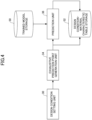
- FIG. 4 is an explanatory diagram illustrating an example of a process of storing the design condition-material characteristic table of the material design support system according to the present embodiment in the design condition-material characteristic table storage.
- FIG. 5 is an explanatory diagram illustrating an example of a process of narrowing the design conditions using the design condition-material characteristic table of the material design support system according to the present embodiment.
- 6061 alloy an example of 6000 series aluminum alloy, will be described as the design target material.
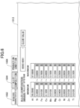
- the design condition setting unit 30 of FIG. 4 causes the user terminal 12 to display an input screen 1012 as illustrated in FIG. 6 for the user to set a range of the design condition for the design target material.
- FIG. 6 is an image diagram of an example of the input screen.
- a display page is switched by a selection operation of tabs 1002 to 1006.
- the input screen 1012 is switched to a display page for the user to set a range of the required characteristic of the design target material.
- the input screen 1012 is switched to a display page for the user to set a range of the composition among the design conditions for the design target material.
- the selection operation of the tab 1006 the input screen 1012 is switched to a display page for the user to set a range of the production condition among the design conditions for the design target material.
- the input screen 1012 of FIG. 6 is an example of the display page for the user to set the range of the composition among the design conditions for the design target material.
- FIG. 6 illustrates an example of the display page for the user to set the minimum and maximum values of the items related to the composition among the design conditions for the design target material.
- the items related to the composition include, for example, elemental species such as Si, Fe, Cu, Mn, Mg, Cr, Ni, Zn, and Ti as additives in mass percentage (mass%).
- the mass percentage of Al is expressed by "1000 - (sum of the mass percentages of the above elements)".
- the display page switched by the selection operation of the tab 1006 is a display page for the user to set the range of the production condition among the design conditions for the design target material.
- the minimum and maximum values of items related to the production condition are to be set.
- the items of the production condition include: temperature (°C) and time (h) for each process such as annealing, solution annealing, artificial age hardening, natural aging, hot working, cold working, stabilization, homogenization, and the like as items related to heat treatment; and processing rate, pressing ratio, surface reduction ratio, product shape, and the like as items related to processing conditions.
- the design condition setting unit 30 receives settings from the user for the range of the design condition for the 6061 alloy.
- the exhaustive prediction point generation unit 34 generates a plurality of exhaustive prediction points within the range of the design condition for the 6061 alloy of which the settings are received from the user by the design condition setting unit 30.
- the range of mass percentage of Si in the item related to the composition and the range of annealing time in the item related to the production condition are set.
- the exhaustive prediction point generation unit 34 calculates a plurality of numerical values at random for each item within the range of mass percentage of Si in the item related to the composition and the range of annealing time in the item related to the production condition.
- the exhaustive prediction point generation unit 34 generates all combinations of the plurality of numerical values for each item and outputs them as exhaustive prediction points.
- the prediction unit 36 reads the trained model from the trained model storage 50, inputs the plurality of exhaustive prediction points generated by the exhaustive prediction point generation unit 34 into the trained model, and predicts the characteristic value of the 6061 alloy for each of the plurality of exhaustive prediction points.
- the trained model storage 50 stores the trained model in which the correspondence between input information including design conditions for the 6061 alloy and characteristic values of the 6061 alloy have been previously acquired by machine learning and formulated.
- Examples of the items of the characteristic value include tensile strength, 0.2% proof stress, elongation, coefficient of linear expansion, Young's modulus, Poisson's ratio, fatigue strength, hardness, creep property, shear strength, Charpy impact value, specific heat, thermal conductivity, electrical resistivity, density, solidus, liquidus, and the like.
- Examples of the fatigue strength include tensile strength of a material after repeated loading tests (repeated tensile compression and the like) for 10 million cycles, and the stress value is used as the characteristic value.
- the prediction unit 36 inputs the exhaustive prediction points generated by the exhaustive prediction point generation unit 34 into the trained model and stores the predicted characteristic value (output) of the 6061 alloy, in association with the exhaustive prediction points (input), in the design condition-material characteristic table storage 52.
- FIG. 7 is a configuration diagram of an example of the design condition-material characteristic table. As illustrated in FIG. 7 , the design condition-material characteristic table is stored in the same row of the design condition-material characteristic table storage 52, in which inputs to the trained model (the production condition and alloy composition) and outputs from the trained model (the predicted characteristic) are combined as one data set. Each row of the design condition-material characteristic table is an individual data set. Each column of the design condition-material characteristic table stores the numerical values of each item of input and output of the trained model.
- the material design support system 1 can generate a group of data sets of a plurality of design conditions (the exhaustive prediction points) within the range of the design condition for the 6061 alloy and characteristic values predicted using the trained model, by performing an operation for setting (specifying) the range of the design condition for the 6061 alloy by a user.
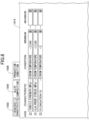
- the required characteristic setting unit 32 of FIG. 5 causes the user terminal 12 to display an input screen 1014 as illustrated in FIG. 8 , for example, for the user to set the range of the required characteristic of the 6061 alloy.
- FIG. 8 is an image diagram of an example of the input screen.
- the input screen 1014 of FIG. 8 is an example of a display page switched by the selection operation of the tab 1002.
- FIG. 8 illustrates an example of a display page for setting the request characteristic. Because the items of the request characteristic are the same as the items of the characteristic value described above, description thereof is omitted.
- "tensile strength” and "0.2% proof stress” are set as the items of the request characteristic.
- "390 MPa or more” is set as the range of the item “tensile strength” of the required characteristic.
- "330 MPa or more” is set as the range of the item "0.2% proof strength" of the required characteristic.
- the design condition adjustment unit 38 extracts a data set from the design condition-material characteristic table storage 52, and by using the data set, displays an output screen as described later on the user terminal 12 for checking by the user.
- FIG. 9 is an image diagram of an example of the output screen.
- a display page is switched by a selection operation of tabs 1102 to 1106.
- the output screen 1112 is switched to a display page illustrated in FIG. 9 in which each point of the exhaustive prediction points is plotted on three two-dimensional coordinate systems having any two axes of "tensile strength", "0.2% proof strength", and "elongation".
- the user can check the number of exhaustive prediction points that satisfy the range of the required characteristic of the 6061 alloy set by the required characteristic setting unit 32 among the plurality of exhaustive prediction points generated by the exhaustive prediction point generation unit 34.
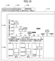
- FIG. 10 is an image diagram of an example of the output screen.
- an upper part 1114a illustrates a box-and-whisker diagram of the range of the composition satisfying the range of the required characteristic of the 6061 alloy.
- a lower part 1114b illustrates a box-and-whisker diagram of the range of the predicted characteristic value satisfying the range of the required characteristic of the 6061 alloy.
- three bars indicate the maximum, median, and minimum values of the range of the predicted characteristic value satisfying the range of the required characteristic of the 6061 alloy
- the lower end of the box indicates the first quantile
- the upper end of the box indicates the third quantile
- the user can extract the exhaustive prediction point satisfying the range of the required characteristic of the 6061 alloy set by the required characteristic setting unit 32 out of the plurality of exhaustive prediction points generated by the exhaustive prediction point generation unit 34, and check the range of the composition and the range of the predicted characteristic value corresponding to the exhaustive prediction point.
- the user can see that the maximum value of tensile strength predicted as one of the characteristic values of the 6061 alloy is "399.74", the maximum value of 0.2% proof stress predicted as one of the characteristic values of the 6061 alloy is "335.95”, and the maximum value of elongation predicted as one of the characteristic values of the 6061 alloy is "17.57”.
- the output screen 1112 illustrated in FIG. 9 or the output screen 1114 illustrated in FIG. 10 may change to an output screen that includes a table presenting the range of the composition satisfying the range of the required characteristic of the 6061 alloy, or presenting the composition, the production condition, and the predicted characteristic value of each of the exhaustive prediction points.
- the design condition adjustment unit 38 displays an input screen 1212 illustrated in FIG. 11 , for example, to the user terminal 12 and proposes a narrowed range of the design condition of the 6061 alloy to the user.
- FIG. 11 is an image diagram of an example of the input screen.
- the range of the design condition set by the user is illustrated on the left side, and the range of the design condition (a proposed material) in which the range of the design condition set by the user is narrowed is illustrated on the right side.
- the display page is switched by the selection operation of tabs 1202 to 1206.
- the input screen 1212 is switched to a display page for the user to reset the range of the required characteristic of the 6061 alloy.
- the input screen 1212 is switched to a display page for the user to reset the range of the composition among the design conditions for the 6061 alloy.
- the selection operation of the tab 1206 the input screen 1212 is switched to a display page for the user to reset the range of the production condition among the design conditions for the 6061 alloy.
- the design condition adjustment unit 38 extracts, for example, an exhaustive prediction point that satisfies the range of the required characteristic of the 6061 alloy set by the required characteristic setting unit 32, and narrows the range of the design condition based on the extracted exhaustive prediction point.
- the design condition adjustment unit 38 proposes the range of the design condition corresponding to the exhaustive prediction point that satisfies the range of the required characteristic to the user, as the narrowed range of the design condition.
- the design condition adjustment unit 38 may expand, by a predetermined percentage, the range of the design condition corresponding to the exhaustive prediction point that satisfies the range of the required characteristic, and propose the expanded range of the design condition to the user, as the narrowed range of the design condition.
- FIG. 12 is an image diagram of an example of the input screen.
- the user can regenerate the exhaustive prediction points from the narrowed range of the design condition for the 6061 alloy and can re-predict the characteristic value of the 6061 alloy for each of the regenerated exhaustive prediction points.
- the exhaustive prediction point generation unit 34 of FIG. 5 When the exhaustive prediction point generation unit 34 of FIG. 5 receives the information of the narrowed range of the design condition for the 6061 alloy from the design condition adjustment unit 38, the exhaustive prediction point generation unit 34 regenerates the exhaustive prediction points from the narrowed range of the design condition for the 6061 alloy.
- the prediction unit 36 inputs the plurality of exhaustive prediction points regenerated from the narrowed range of the design condition for the 6061 alloy to the trained model, and re-predicts the characteristic value of the 6061 alloy for each of the regenerated exhaustive prediction points.
- the design condition-material characteristic table storage 52 restores the characteristic value of the 6061 alloy for each of the re-predicted exhaustive prediction points in the design condition-material characteristic table, in association with the exhaustive prediction point used for the re-prediction of the characteristic value.
- the design condition adjustment unit 38 extracts a data set from the design condition-material characteristic table storage 52, and by using the data set, displays an output screen as illustrated in FIG. 13 on the user terminal 12 for checking by the user.
- FIG. 13 is an image diagram of an example of the output screen.
- the display page is switched by the selection operation of the tabs 1102 to 1106.
- the output screen 1112 is switched to the display page illustrated in FIG. 13 in which each point of the exhaustive prediction points is plotted in three two-dimensional coordinate systems having any two axes of "tensile strength", "0.2% proof strength", and "elongation".
- the exhaustive prediction points satisfying the range of the required characteristic of the 6061 alloy set by the required characteristic setting unit 32 are plotted with a triangle " ⁇ "
- the exhaustive prediction points not satisfying the range of the required characteristic of the 6061 alloy set in the required characteristic setting unit 32 are plotted with a circle " ⁇ ".
- the user can see that the number of exhaustive prediction points that satisfy the range of the required characteristic of the 6061 alloy set by the required characteristic setting unit 32 has increased from before narrowing the range of the design condition for the 6061 alloy.
- FIG. 14 is an image diagram of an example of the output screen.
- the upper part 1114a illustrates a box-and-whisker diagram of the range of the composition satisfying the range of the required characteristic of the 6061 alloy.
- the lower part 1114b illustrates a box-and-whisker diagram of the range of the re-predicted characteristic value satisfying the range of the required characteristic of the 6061 alloy.
- the user can re-extract the exhaustive prediction point satisfying the range of the required characteristic of the 6061 alloy set by the required characteristic setting unit 32 among the plurality of exhaustive prediction points regenerated by the exhaustive prediction point generation unit 34, and check the range of the re-predicted characteristic value corresponding to the exhaustive prediction point.
- the maximum value of tensile strength predicted as one of the characteristic values of the 6061 alloy increases from “399.74" to "402.12".
- the maximum value of 0.2% proof stress predicted as one of the characteristic values of the 6061 alloy increases from "335.95” to "338.47”.
- the maximum value of elongation predicted as one of the characteristic values of the 6061 alloy increases from "17.57” to "17.87".
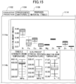
- FIG. 15 is an image diagram of an example of the output screen.
- a user operation for changing the range of the required characteristic of the 6061 alloy is received from the box-and-whisker diagram of the lower part 1114b.
- an operation for increasing the lower limit value of the tensile strength which is an example of the required characteristic, from "390.00” to "399.00" is received from the user of the user terminal 12.
- an operation for increasing the lower limit value of the tensile strength may be received from the user by moving the bar indicating the minimum value of the box-and-whisker diagram in the lower part 1114b upward.
- the operation for increasing the lower limit value of the tensile strength which is an example of the required characteristic, may be an operation for extracting the upper data (such as the data of the upper 2.5%) among the tensile strengths of the plurality of exhaustive prediction points predicted as one of the characteristic values of the 6061 alloy.
- the output screen 1114 of FIG. 15 is an example of an operation for increasing the lower limit value of the 0.2% proof strength, which is an example of the required characteristic, received from the user of the user terminal 12, as indicated by an arrow B.
- the output screen 1114 illustrated in FIG. 15 is an example in which an operation to raise the lower limit of elongation, which is an example of the required characteristic, as indicated by an arrow C, and an operation to lower the upper limit of elongation, which is an example of the required characteristic, as indicated by an arrow D, are received from the user of the user terminal 12.
- the output screen 1114 illustrated in FIG. 15 receives the user operation to change the upper limit and the lower limit of the required characteristic, as indicated by the arrows A to D, the range of the composition that satisfies the range of the required characteristic of the 6061 alloy displayed in the box-and-whisker diagram in the upper part 1114a is changed in accordance with the change of the range of the required characteristic.
- both the state before the user operation is received and the state after the user operation is received may be displayed in different display formats (different colors, different concentrations, and the like).
- the user can narrow the range of the design condition for the 6061 alloy to satisfy the range of the required characteristic of the 6061 alloy.
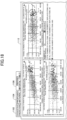
- the design condition adjustment unit 38 displays the input screen 1212 illustrated in FIG. 16 , for example, on the user terminal 12 to propose the narrowed range of the design condition for the 6061 alloy to the user.
- FIG. 16 is an image diagram of an example of the input screen.
- the range of the previously re-set design condition is illustrated on the left, and the range of the previously re-set design condition further narrowed (a proposed material) is illustrated on the right.
- the design condition adjustment unit 38 extracts, for example, the exhaustive prediction point that satisfies the range of the modified required characteristic of the 6061 alloy, and narrows the range of the design condition based on the extracted exhaustive prediction point. For example, the design condition adjustment unit 38 proposes the range of the design condition corresponding to the exhaustive prediction point that satisfies the modified range of the required characteristic to the user as the range of the narrowed design condition.
- FIG. 17 is an image diagram of an example of the input screen.
- the user can regenerate the exhaustive prediction points from the narrowed range of the design condition for the 6061 alloy and re-predict the characteristic value of the 6061 alloy for each of the regenerated exhaustive prediction points.
- the exhaustive prediction point generation unit 34 of FIG. 5 When the exhaustive prediction point generation unit 34 of FIG. 5 receives the information of the narrowed range of the design condition for the 6061 alloy from the design condition adjustment unit 38, the exhaustive prediction point generation unit 34 regenerates the exhaustive prediction points from the narrowed range of the design condition for the 6061 alloy.
- the prediction unit 36 inputs the plurality of exhaustive prediction points regenerated from the narrowed range of the design condition for the 6061 alloy to the trained model, and re-predicts the characteristic value of the 6061 alloy for each of the regenerated exhaustive prediction points.
- the design condition-material characteristic table storage 52 restores the characteristic value of the 6061 alloy for each of the re-predicted exhaustive prediction points in the design condition-material characteristic table, in association with the exhaustive prediction point used for the re-prediction of the characteristic value.
- the design condition adjustment unit 38 extracts a data set from the design condition-material characteristic table storage 52, and by using the data set, displays an output screen as illustrated in FIG. 18 on the user terminal 12 for checking by the user.
- FIG. 18 is an image diagram of an example of the output screen.
- the display page is switched by the selection operation of the tabs 1102 to 1106.
- the exhaustive prediction points satisfying the range of the required characteristic of the 6061 alloy set by the required characteristic setting unit 32 are plotted with a triangle " ⁇ "
- the exhaustive prediction points not satisfying the range of the required characteristic of the 6061 alloy set by the required characteristic setting unit 32 are plotted with a circle " ⁇ ".
- the user can see that the number of exhaustive prediction points that satisfy the range of the required characteristic of the 6061 alloy set by the required characteristic setting unit 32 has decreased from before narrowing the range of the required characteristic of the 6061 alloy.
- FIG. 19 is an image diagram of an example of the output screen.
- the upper part 1114a illustrates a box-and-whisker diagram of the range of the composition satisfying the range of the required characteristic of the 6061 alloy.
- the lower part 1114b illustrates a box-and-whisker diagram of the range of the re-predicted characteristic value satisfying the range of the required characteristic of the 6061 alloy.
- the user can re-extract the exhaustive prediction point satisfying the modified range of the required characteristic of the 6061 alloy among the plurality of exhaustive prediction points regenerated by the exhaustive prediction point generation unit 34, and check the range of the re-predicted characteristic value corresponding to the exhaustive prediction point.
- the maximum value of tensile strength predicted as one of the characteristic values of the 6061 alloy increases from “402.12” to "402.87".
- the maximum value of 0.2% proof stress predicted as one of the characteristic values of the 6061 alloy decreases from "338.47” to "338.23”.
- the maximum value of elongation predicted as one of the characteristic values of the 6061 alloy decreases from "17.87” to "17.49”.
- the design objective is "maximizing tensile strength”
- the example of the output screen 1114 of FIG. 19 satisfies the design objective more than the example of the output screen 1114 of FIG. 14 .
- the user can check, for example, the range of the composition satisfying the range of the required characteristic of the 6061 alloy and the re-predicted range of the characteristic value satisfying the range of the required characteristic of the 6061 alloy, as illustrated in the output screen 1114 illustrated in FIG. 20 .
- the maximum value of tensile strength predicted as one of the characteristic values of the 6061 alloy is increased to "404.65".
- FIG. 21 is a flowchart illustrating an example of a process of storing the design condition-material characteristic table in the design condition-material characteristic table storage of the material design support system according to the present embodiment.
- step S10 the design condition setting unit 30 causes the user terminal 12 to display the input screen 1012 as illustrated in FIG. 6 , for example, for the user to set the range of the design condition for the 6061 alloy as the design target material.
- step S12 the required characteristic setting unit 32 causes the user terminal 12 to display the input screen 1014 as illustrated in FIG. 8 , for example, for the user to set the range of the required characteristic for the 6061 alloy as the design target material.
- step S14 the exhaustive prediction point generation unit 34 generates a plurality of exhaustive prediction points, such as 10,000 points, within the range of the design condition for the 6061 alloy that the design condition setting unit 30 has received from the user.
- step S16 the prediction unit 36 selects one unselected exhaustive prediction point from the plurality of exhaustive prediction points generated by the exhaustive prediction point generation unit 34.
- step S18 the prediction unit 36 reads out the trained model from the trained model storage 50.
- the prediction unit 36 inputs one exhaustive prediction point selected in step S16 into the trained model and predicts the characteristic value of the one exhaustive prediction point selected in step S16.
- step S20 the design condition-material characteristic table storage 52 generates a data set in which the one exhaustive prediction point selected in step S16 is associated with a characteristic value predicted by inputting the one exhaustive prediction point into the trained model, and stores the data set in the design condition-material characteristic table.
- step S22 the prediction unit 36 determines whether there is an unselected exhaustive prediction point in the exhaustive prediction points generated by the exhaustive prediction point generation unit 34. When there is an unselected exhaustive prediction point, the prediction unit 36 returns to the process in step S16 and continues generating the data set.
- FIG. 22 is a flowchart illustrating an example of the process for narrowing the design condition using the design condition-material characteristic table of the material design support system according to the present embodiment.
- step S40 the design condition adjustment unit 38 extracts a data set satisfying the required characteristic from the design condition-material characteristic table storage 52.
- step S42 by using the extracted data set, the design condition adjustment unit 38 causes the user terminal 12 to display the output screen 1114 illustrated in FIG. 10 , for example, for the user to check the range of the design condition satisfying the range of the required characteristic of the 6061 alloy and the range of the predicted characteristic value.
- the design condition adjustment unit 38 proceeds to the process of step S44.
- the design condition adjustment unit 38 displays the input screen 1212 illustrated in FIG. 11 , for example, on the user terminal 12, and proposes the narrowed range of the design condition for the 6061 alloy to the user.
- the user when the user selects the narrowed range of the design condition for the 6061 alloy proposed in step S44, the user performs a selection operation such as pressing the "reflect proposed material” button 1208 on the input screen 1212 illustrated in FIG. 11 .
- step S46 the design condition adjustment unit 38 determines whether the narrowed range of the design condition for the 6061 alloy proposed in step S44 has been selected by the user. When the narrowed range of the design condition for the 6061 alloy proposed in step S44 has been selected by the user, the design condition adjustment unit 38 proceeds to the process in step S48, changes to the narrowed range of the design condition for the 6061 alloy proposed in step S44, and returns to the process in step S14.
- the exhaustive prediction points can be regenerated from the narrowed range of the design condition for the 6061 alloy, and the characteristic value of the 6061 alloy can be re-predicted for each of the regenerated exhaustive prediction points.
- step S44 the design condition adjustment unit 38 proceeds to the process of step S50.
- step S50 the design condition adjustment unit 38 determines whether or not a user operation to adjust the range of the required characteristic has been received via the output screen 1114 of FIG. 14 and the like, for example.
- the design condition adjustment unit 38 proceeds to the process in step S52.
- the design condition adjustment unit 38 extracts a data set satisfying the adjusted required characteristic from the design condition-material characteristic table.
- the design condition adjustment unit 38 causes the user terminal 12 to display the output screen 1114 illustrated in FIG. 15 , for example, for the user to check the range of the design condition satisfying the adjusted range of the required characteristic and the range of the predicted characteristic value.
- the design condition adjustment unit 38 skips the process in steps S52 and S54.
- step S56 the design condition adjustment unit 38 determines whether the user operation to end the screen display is received. When the user operation to end the screen display is not received, the design condition adjustment unit 38 returns to the process of step S44. When the user operation to end the screen display is received, the design condition adjustment unit 38 ends the information display process illustrated in FIG. 22 .
- the design condition be narrowed to the range that satisfies the required characteristic of the design target material, based on the characteristic value of the design target material predicted by the trained model and the required characteristic of the design target material, but also, production constraints based on the user's experience can be taken into account.
- the process illustrated in FIGS. 21 and 22 includes user operations to select or not to select the narrowed range of the design condition for the 6061 alloy, and user operations to adjust the range of the required characteristic to narrow the range of the design condition for the 6061 alloy.
- the embodiment may be such that: the user operation to select or not to select the narrowed range of the design condition for the 6061 alloy and the user operation to adjust the range of the required characteristic to narrow the range of the design condition for the 6061 alloy, are omitted and automated.
- FIG. 23 is a flowchart illustrating an example of the process to narrow the design condition using the design condition-material characteristic table of the material design support system according to the present embodiment.
- step S100 the design condition setting unit 30 causes the user terminal 12 to display the input screen 1012 as illustrated in FIG. 6 , for example, for the user to set the range of the design condition for the 6061 alloy as the design target material.
- the required characteristic setting unit 32 causes the user terminal 12 to display the input screen 1014 as illustrated in FIG. 8 , for example, for the user to set the range of the required characteristic for the 6061 alloy as the design target material.
- the required characteristic setting unit 32 allows the user to set the design objective.
- the design objective is, for example, "maximizing tensile strength", and enables determination using the predicted characteristic value.
- the exhaustive prediction point generation unit 34 generates a plurality of exhaustive prediction points, such as 10,000 points, within the range of the design condition for the 6061 alloy, which the design condition setting unit 30 has received from the user.
- the prediction unit 36 inputs the exhaustive prediction points generated by the exhaustive prediction point generation unit 34 into the trained model to predict the characteristic value of each of the plurality of exhaustive prediction points.
- the design condition-material characteristic table storage 52 generates a data set in which the exhaustive prediction point is associated with the characteristic value predicted by inputting the exhaustive prediction point into the trained model, and stores the data in the design condition-material characteristic table.
- step S110 the design condition adjustment unit 38 extracts a data set satisfying the required characteristic from the design condition-material characteristic table.
- the design condition adjustment unit 38 can analyze, by using the extracted data set, the range of the design condition satisfying the range of the required characteristic of the 6061 alloy and the predicted range of the characteristic value.
- step S112 the design condition adjustment unit 38 determines whether the design objective such as "maximizing tensile strength" set in step S104 has been achieved. When the design objective has not been achieved, the design condition adjustment unit 38 proceeds to the process in step S114.
- step S114 the material design support system 1 according to the present embodiment regenerates a plurality of exhaustive prediction points within the range of the design condition narrowed to the range satisfying the range of the required characteristic, and returns to the process in step S108.
- a step may be added in which the data having the highest tensile strength (the top 2.5% of the data, and the like) is extracted and a plurality of exhaustive prediction points are regenerated within the range of the design condition.
- the material design support system 1 repeats the processes of steps S108 to S114, narrowing the design objective to the range of the design condition satisfying the range of the required characteristic, until the design objective such as "maximizing tensile strength" set in step S104 is achieved.
- the material design support system 1 according to the present embodiment ends the processing of the flowchart of FIG. 23 .
- the process of narrowing the design condition to the range that satisfies the required characteristic of the design target material, based on the required characteristic of the design target material and the characteristic value of the design target material predicted by the trained model, can be automated.
- the results of the processing for supporting the optimization of the design condition for the material, performed by the material design support apparatus 10 according to the present embodiment may be used as input information to a production apparatus for generating a design target material, such as an aluminum alloy and the like.
- the results of the processing performed by the material design support apparatus 10 according to the present embodiment may be input to the production apparatus.
- technical parameters of the production apparatus are determined such that design target materials in a range satisfying the required characteristic are produced, and the production process can be controlled.
- the exhaustive prediction point generation unit 34 generates one set of a plurality of exhaustive prediction points within the set range of the design condition for the design target material, but a plurality of sets may be generated, and the set that best satisfies the required characteristic may be selected and used.
- the material design support system 1 can provide a material design support apparatus, a material design support method, and a program for supporting efficient optimization of the design conditions for the design target materials.
Landscapes
- Engineering & Computer Science (AREA)
- Physics & Mathematics (AREA)
- General Physics & Mathematics (AREA)
- Theoretical Computer Science (AREA)
- Manufacturing & Machinery (AREA)
- Business, Economics & Management (AREA)
- Evolutionary Computation (AREA)
- Automation & Control Theory (AREA)
- Human Computer Interaction (AREA)
- General Business, Economics & Management (AREA)
- Computer Vision & Pattern Recognition (AREA)
- Strategic Management (AREA)
- Primary Health Care (AREA)
- Marketing (AREA)
- Human Resources & Organizations (AREA)
- General Health & Medical Sciences (AREA)
- Economics (AREA)
- Artificial Intelligence (AREA)
- Tourism & Hospitality (AREA)
- Health & Medical Sciences (AREA)
- Medical Informatics (AREA)
- Software Systems (AREA)
- Computer Hardware Design (AREA)
- Geometry (AREA)
- General Engineering & Computer Science (AREA)
- Management, Administration, Business Operations System, And Electronic Commerce (AREA)
Abstract
Description
- The present disclosure relates to a material design support apparatus, a material design support method, and a program.
- In conventional design of metallic materials, in order to produce metallic materials with desired characteristics (tensile strength, hardness, toughness, plastic workability, and the like), component compositions of elements in metals and production conditions are determined empirically or by trial and error.
- However, as the number of variable items increases in the component compositions of elements in metals and in the production conditions, the human and time burden of designing metallic materials has increased. In order to reduce the human and time burden described above, it has been proposed to design materials through optimization calculations and the like using a computer.
- For example, in
Patent Document 1, in order to reduce the increase in the computational load on the design of metallic materials, a design support method has been proposed, which includes: a search step of inputting a desired characteristic value in a database that is generated by using at least one mathematical model in which input information including a component composition of elements in metals and a production condition, and output information including a characteristic value of a metallic material, are related, and stores output data of the mathematical model in relation to input data for each mesh in which a range of inputs corresponding to the input information is separated by a plurality of sections, and retrieving a component composition of elements in metals and a production condition; and a presentation step of presenting the component composition of the elements in metals and the production condition corresponding to the desired characteristic value retrieved by the search step. - Patent Document 1:
Japanese Patent No. 6617842 - However, when the number of dimensions of design conditions (the number of combinations of conditions) of materials is large, a large amount of calculation time and resources are required to optimize design conditions. Therefore, an efficient method for optimizing design conditions for materials is required.
- One object of the present disclosure is to provide a material design support device, a material design support method, and a program for supporting efficient optimization of design conditions for materials.
- The present disclosure includes the following configurations.
- [1] A material design support apparatus for supporting optimization of a design condition for a material, the material design support apparatus including:
- a design condition setting unit configured to set a range of a design condition for a material;
- a required characteristic setting unit configured to set a range of a required characteristic of the material;
- an exhaustive prediction point generation unit configured to generate a plurality of exhaustive prediction points within the range of the design condition;
- a prediction unit configured to input the exhaustive prediction points into a trained model in which a correspondence between a design condition for the material and a characteristic value of the material is learned, thereby to predict a characteristic value of the material; and
- a design condition adjustment unit configured to adjust, based on the predicted characteristic value of the material for each of the exhaustive prediction points and the range of the required characteristic of the material, a range of the design condition for the material in which a plurality of exhaustive prediction points are subsequently generated.
- [2] The material design support apparatus according to [1], wherein the design condition adjustment unit is configured to extract, from the predicted characteristic value of the material for each of the exhaustive prediction points, a range of the design condition for the material that satisfies the range of the required characteristic of the material, and to narrow, based on the extracted range of the design condition for the material, the range of the design condition for the material in which the plurality of exhaustive prediction points are subsequently generated.
- [3] The material design support apparatus according to [1] or [2], further including:
- an information display unit configured to display: the range of the design condition for the material corresponding to the plurality of exhaustive prediction points that satisfies the range of the required characteristic of the material; and a range of predicted characteristic values of the material of the plurality of exhaustive prediction points that satisfies the range of the required characteristic of the material,
- wherein the design condition adjustment unit is configured to change, in response to a user operation to change the range of the required characteristic of the material that is displayed on the information display unit, the range of the design condition for the material.
- [4] The material design support apparatus according to any one of [1] to [3], wherein
- the design condition adjustment unit is configured to repeat, until a range of the predicted characteristic value of the material of each of the plurality of exhaustive prediction points achieves a design objective, a process of adjusting the range of the design condition for the material in which the plurality of exhaustive prediction points are subsequently generated,
- the exhaustive prediction point generation unit is configured to regenerate a plurality of exhaustive prediction points within the range of the design condition for the material that is adjusted by the design condition adjustment unit, and
- the prediction unit is configured to input the regenerated exhaustive prediction points into the trained model, thereby to re-predict a characteristic value of the material.
- [5] The material design support apparatus according to any one of [1] to [4], wherein the design condition for the material includes a composition and a production condition of the material.
- [6] A material design support method executed by a computer for supporting optimization of a design condition for a material, the material design support method including:
- a step of setting a range of a design condition for a material;
- a step of setting a range of a required characteristic of the material;
- a step of generating a plurality of exhaustive prediction points within the range of the design condition;
- a step of inputting the exhaustive prediction points into a trained model in which a correspondence between a design condition for the material and a characteristic value of the material is learned, thereby predicting a characteristic value of the material; and
- a step of adjusting, based on the predicted characteristic value of the material for each of the exhaustive prediction points and the range of the required characteristic of the material, a range of the design condition for the material in which a plurality of exhaustive prediction points are subsequently generated.
- [7] A program for causing a computer for supporting optimization of a design condition for a material, to execute:
- a step of setting a range of a design condition for a material;
- a step of setting a range of a required characteristic of the material;
- a step of generating a plurality of exhaustive prediction points within the range of the design condition;
- a step of inputting the exhaustive prediction points into a trained model in which a correspondence between a design condition for the material and a characteristic value of the material is learned, thereby predicting a characteristic value of the material; and
- a step of adjusting, based on the predicted characteristic value of the material for each of the exhaustive prediction points and the range of the required characteristic of the material, a range of the design condition for the material in which a plurality of exhaustive prediction points are subsequently generated.
- According to the present disclosure, it is possible to support efficient optimization of design conditions for materials.
-
- [
FIG. 1] FIG. 1 is a configuration diagram illustrating an example of a material design support system according to one embodiment. - [
FIG. 2] FIG. 2 is a hardware configuration diagram illustrating an example of a computer according to one embodiment. - [
FIG. 3] FIG. 3 is a functional configuration diagram illustrating an example of the material design support system according to one embodiment. - [
FIG. 4] FIG. 4 is an explanatory diagram illustrating an example of a process of storing a design condition-material characteristic table of the material design support system in a design condition-material characteristic table storage according to one embodiment. - [
FIG. 5] FIG. 5 is an explanatory diagram illustrating an example of a process of narrowing design conditions using the design condition-material characteristic table of the material design support system according to one embodiment. - [
FIG. 6] FIG. 6 is an image diagram illustrating an example of an input screen. - [
FIG. 7] FIG. 7 is a configuration diagram illustrating an example of the design condition-material characteristic table. - [
FIG. 8] FIG. 8 is an image diagram illustrating an example of an input screen. - [
FIG. 9] FIG. 9 is an image diagram illustrating an example of an output screen. - [
FIG. 10] FIG. 10 is an image diagram illustrating an example of an output screen. - [
FIG. 11] FIG. 11 is an image diagram illustrating an example of an input screen. - [
FIG. 12] FIG. 12 is an image diagram illustrating an example of an input screen. - [
FIG. 13] FIG. 13 is an image diagram illustrating an example of an output screen. - [
FIG. 14] FIG. 14 is an image diagram illustrating an example of an output screen. - [
FIG. 15] FIG. 15 is an image diagram illustrating an example of an output screen. - [
FIG. 16] FIG. 16 is an image diagram illustrating an example of an input screen. - [
FIG. 17] FIG. 17 is an image diagram illustrating an example of an input screen. - [
FIG. 18] FIG. 18 is an image diagram illustrating an example of an output screen. - [
FIG. 19] FIG. 19 is an image diagram illustrating an example of an output screen. - [
FIG. 20] FIG. 20 is an image diagram illustrating an example of an output screen. - [
FIG. 21] FIG. 21 is a flowchart illustrating an example of a process of storing the design condition-material characteristic table of the material design support system in the design condition-material characteristic table storage according to one embodiment. - [
FIG. 22] FIG. 22 is a flowchart illustrating an example of a process of narrowing the design conditions using the design condition-material characteristic table of the material design support system according to one embodiment. - [
FIG. 23] FIG. 23 is a flowchart illustrating an example of a process of narrowing the design conditions using the design condition-material characteristic table of the material design support system according to one embodiment. - Next, embodiments of the present invention will be described in detail. The present invention is not limited to the following embodiments.
-
FIG. 1 is a configuration diagram illustrating an example of a material design support system according to one embodiment. A materialdesign support system 1 ofFIG. 1 includes a materialdesign support apparatus 10 and auser terminal 12. The materialdesign support apparatus 10 and theuser terminal 12 are connected via acommunication network 18, such as a local area network (LAN), the Internet, or the like, and are communicable with each other to perform data communication. - The
user terminal 12 is an information processing terminal such as a PC, a tablet terminal, a smartphone, or the like, operated by a user such as a material designer. Theuser terminal 12 receives an input operation or a change operation of information necessary for optimizing a design condition for a material from the user, and causes the materialdesign support apparatus 10 to execute the processing for supporting the optimization of the design condition for the material. Theuser terminal 12 receives the result of the processing for supporting the optimization of the design condition for the material executed by the materialdesign support apparatus 10, and displays the result on a display device for checking by the user, for example. - The material
design support apparatus 10 is an information processing apparatus such as a PC for executing the processing for supporting the optimization of the design condition for the material. The materialdesign support apparatus 10 executes the processing for supporting the optimization of the design condition for the material using a trained model in which a correspondence between a design condition for a material and a characteristic value of the material is learned. The materialdesign support apparatus 10 transmits the result of the executed processing for supporting the optimization of the design condition for the material to theuser terminal 12. - The material
design support system 1 illustrated inFIG. 1 is an example, and there are various system configuration examples depending on the application and purpose. For example, the materialdesign support apparatus 10 may be implemented by a plurality of computers or may be implemented as a cloud computing service. The materialdesign support system 1 illustrated inFIG. 1 may be implemented by a stand-alone computer. - The material
design support apparatus 10 and theuser terminal 12 illustrated inFIG. 1 are implemented in acomputer 500 having a hardware configuration illustrated inFIG. 2 , for example. -
FIG. 2 is a hardware configuration diagram illustrating an example of the computer according to the one embodiment. Thecomputer 500 ofFIG. 2 includes aninput device 501, adisplay device 502, an external I/F 503, aRAM 504, aROM 505, aCPU 506, a communication I/F 507, aHDD 508, or the like, which are connected to each other via a bus B. Theinput device 501 and thedisplay device 502 may be connected and used. - The
input device 501 is a touchscreen panel, operation keys or buttons, a keyboard, a mouse, or the like used by the user to input various signals. Thedisplay device 502 includes a display, such as a liquid crystal display, an organic EL display, or the like for displaying a screen, a speaker for outputting sound data, such as voice, sound, or the like, and the like. The communication I/F 507 is an interface used by thecomputer 500 to perform the data communication. - In addition, the
HDD 508 is an example of a non-volatile storage device that stores programs and data. The stored programs and data include an operating system (OS) that is basic software for controlling theentire computer 500, applications for providing various functions on the OS, or the like. Thecomputer 500 may use a drive device (for example, a solid state drive (SSD) or the like) using a flash memory as a storage media, in place of theHDD 508. - The external I/
F 503 is an interface provided with respect to an external device. Examples of the external device include arecording medium 503a or the like. Thus, thecomputer 500 can read from and/or write to therecording medium 503a via the external I/F 503. Examples of therecording medium 503a include a flexible disk, a CD, a DVD, an SD memory card, a USB memory, or the like. - The
ROM 505 is an example of a non-volatile semiconductor memory (storage device) that can retain programs and data even when the power is turned off. TheROM 505 stores programs and data, such as a BIOS that is executed when thecomputer 500 is started, OS settings, network settings, or the like. TheRAM 504 is an example of a volatile semiconductor memory (storage device) that temporarily stores the programs and data. - The
CPU 506 is an arithmetic unit that reads the programs and data from a storage device, such as theROM 505, theHDD 508, or the like into theRAM 504, and executes processing to control theentire computer 500 or implement functions thereof. Thecomputer 500 according to the one embodiment implements various functions of the materialdesign support apparatus 10 and of theuser terminal 12, which will be described later, by executing programs. - The configuration of the material
design support system 1 according to the present embodiment will be described below.FIG. 3 is a functional configuration diagram illustrating an example of the material design support system according to the present embodiment. In the configuration diagram ofFIG. 3 , parts unnecessary for explaining the present embodiment are omitted as appropriate. In the present embodiment, the material for which optimization of the design condition is supported is called a design target material. The design target material is, for example, an aluminum alloy. - The material
design support apparatus 10 of the materialdesign support system 1 illustrated inFIG. 3 includes a designcondition setting unit 30, a requiredcharacteristic setting unit 32, an exhaustive predictionpoint generation unit 34, aprediction unit 36, a designcondition adjustment unit 38, a requestresponse control unit 40, a trainedmodel storage 50, and a design condition-materialcharacteristic table storage 52. Theuser terminal 12 includes aninformation display unit 20, anoperation reception unit 22, arequest transmission unit 24, and aresponse reception unit 26. - The
information display unit 20 displays information on thedisplay device 502 or the like. For example, theinformation display unit 20 displays on the display device 502 a screen for receiving an input operation of information necessary for optimizing the design condition for the design target material, a screen for displaying the result of the processing for supporting the optimization of the design condition for the design target material, and the like. Theoperation reception unit 22 receives, from the user, the input operation or the change operation of information necessary for optimizing the design condition for the design target material. Therequest transmission unit 24 transmits a request for the processing for supporting the optimization of the design condition for the design target material, to the materialdesign support apparatus 10. Theresponse reception unit 26 receives a response to the request for the processing transmitted by therequest transmission unit 24. - The design
condition setting unit 30 sets a range of a design condition for an aluminum alloy, which is an example of a design target material. For example, the designcondition setting unit 30 causes theuser terminal 12 to display an input screen of the design condition for the user to set the range of the design condition. The design condition for the design target material includes the composition and the production condition of the design target material as information. - The required
characteristic setting unit 32 sets a range of a required characteristic of the aluminum alloy, which is an example of the design target material. For example, the requiredcharacteristic setting unit 32 causes theuser terminal 12 to display an input screen of the required characteristic for the user to set the range of the required characteristic. - The exhaustive prediction
point generation unit 34 generates a plurality of exhaustive prediction points within the range of the set design condition for the design target material. For example, the exhaustive predictionpoint generation unit 34 calculates a plurality of numerical values, for each of the items such as the composition and the production condition included in the design condition for the design target material, at random or in predetermined increments within the range of the design condition for the design target material, and generates all combinations of the numerical values of the items as a plurality of exhaustive prediction points. The exhaustive predictionpoint generation unit 34 may adjust the time required for optimizing the design condition for the design target material by adjusting the number of exhaustive prediction points to be generated. The exhaustive predictionpoint generation unit 34 generates, for example, 10,000 exhaustive prediction points. - The
prediction unit 36 reads a trained model from the trainedmodel storage 50, inputs the plurality of exhaustive prediction points generated by the exhaustive predictionpoint generation unit 34 into the trained model, and predicts a characteristic value of the design target material for each of the plurality of exhaustive prediction points. The trainedmodel storage 50 stores the trained model in which a correspondence between a design condition for a material such as an aluminum alloy and a characteristic value of the material have been previously acquired by machine learning and formulated. - As the trained model, a supervised training model such as a neural network or a Gaussian process may be applied. The trained model may be obtained by machine learning using training data that includes, for example, design conditions for a material such as an aluminum alloy read from a known material database and characteristic values of the material.
- The design condition-material
characteristic table storage 52 stores, in a design condition-material characteristic table described later, the characteristic value of the design target material for each of the exhaustive prediction points predicted by inputting the plurality of exhaustive prediction points into the trained model, in association with the exhaustive prediction point used for predicting the characteristic value. Thus, the design condition-materialcharacteristic table storage 52 stores the design conditions (the exhaustive prediction points) of the design target material, which are inputs to the trained model, and the characteristic values (the predicted characteristic values) of the design target material, which are outputs from the trained model, in one data set in the same row of the design condition-material characteristic table. - The design
condition adjustment unit 38 extracts a data set satisfying a range of the required characteristic of the design target material set by the requiredcharacteristic setting unit 32 from the design condition-materialcharacteristic table storage 52, and displays an output screen of the range of the design condition satisfying the range of the required characteristic on theuser terminal 12 for checking by the user. - The design
condition adjustment unit 38 displays, by using a data set satisfying the range of the required characteristic of the design target material extracted from the design condition-materialcharacteristic table storage 52, an output screen of the range of the predicted characteristic value of the design target material satisfying the range of the required characteristic on theuser terminal 12 for checking by the user. - The design
condition adjustment unit 38 may change, in response to a user operation to change the range of the required characteristic of the design target material, the display of the range of the design condition satisfying the range of the required characteristic displayed on theuser terminal 12. - Accordingly, the design
condition adjustment unit 38 can extract the range of the design condition that simultaneously satisfies the multidimensional required characteristic, by receiving the operation to set a range of the multidimensional required characteristic from the user. The designcondition adjustment unit 38 can adjust the range of the design condition that simultaneously satisfies the multidimensional required characteristic by receiving the operation to change the range of the multidimensional required characteristic from the user. - For example, the design
condition adjustment unit 38 may narrow the range of the design condition by receiving the operation to change the required characteristic in the direction to be increased from the user. The designcondition adjustment unit 38 may expand the range of the design condition by receiving the operation to change the required characteristic in the direction to be decreased from the user. - Further, the design
condition adjustment unit 38 may narrow the range of the design condition for the design target material used for generating the previous exhaustive prediction points, to the range of the design condition that satisfies the range of the required characteristic of the design target material, as the range of the design condition used for subsequently generating the exhaustive prediction points. The designcondition adjustment unit 38 can narrow the design space of the design target material, by narrowing the range of the design condition of the design target material used for generating the exhaustive prediction points to the range of the design condition that satisfies the range of the required characteristic of the design target material. The designcondition adjustment unit 38 can obtain a more precise range of design conditions by regenerating the exhaustive prediction points within the narrowed range of the design condition and re-predicting the characteristic value of the design target material. - The request
response control unit 40 controls a process of receiving a request from theuser terminal 12 and returning a response to the request to theuser terminal 12. For example, the requestresponse control unit 40 receives a request for the processing for supporting the optimization of the design condition of the design target material from theuser terminal 12 and transmits a response to the received request for the processing to theuser terminal 12. - The processing by the material
design support system 1 according to the present embodiment will be described.FIG. 4 is an explanatory diagram illustrating an example of a process of storing the design condition-material characteristic table of the material design support system according to the present embodiment in the design condition-material characteristic table storage.FIG. 5 is an explanatory diagram illustrating an example of a process of narrowing the design conditions using the design condition-material characteristic table of the material design support system according to the present embodiment. In the following, an example of 6061 alloy, an example of 6000 series aluminum alloy, will be described as the design target material. - The design
condition setting unit 30 ofFIG. 4 causes theuser terminal 12 to display aninput screen 1012 as illustrated inFIG. 6 for the user to set a range of the design condition for the design target material.FIG. 6 is an image diagram of an example of the input screen. In theinput screen 1012 ofFIG. 6 , a display page is switched by a selection operation oftabs 1002 to 1006. By the selection operation of thetab 1002, theinput screen 1012 is switched to a display page for the user to set a range of the required characteristic of the design target material. By the selection operation of thetab 1004, theinput screen 1012 is switched to a display page for the user to set a range of the composition among the design conditions for the design target material. By the selection operation of thetab 1006, theinput screen 1012 is switched to a display page for the user to set a range of the production condition among the design conditions for the design target material. - The
input screen 1012 ofFIG. 6 is an example of the display page for the user to set the range of the composition among the design conditions for the design target material.FIG. 6 illustrates an example of the display page for the user to set the minimum and maximum values of the items related to the composition among the design conditions for the design target material. The items related to the composition include, for example, elemental species such as Si, Fe, Cu, Mn, Mg, Cr, Ni, Zn, and Ti as additives in mass percentage (mass%). The mass percentage of Al is expressed by "1000 - (sum of the mass percentages of the above elements)". - The display page switched by the selection operation of the
tab 1006 is a display page for the user to set the range of the production condition among the design conditions for the design target material. For example, the minimum and maximum values of items related to the production condition are to be set. Examples of the items of the production condition include: temperature (°C) and time (h) for each process such as annealing, solution annealing, artificial age hardening, natural aging, hot working, cold working, stabilization, homogenization, and the like as items related to heat treatment; and processing rate, pressing ratio, surface reduction ratio, product shape, and the like as items related to processing conditions. - Details of the display page that is switched by the selection operation of the
tab 1002 for the user to set the range of the required characteristic of the design target material will be described later. - Returning to
FIG. 4 , the designcondition setting unit 30 receives settings from the user for the range of the design condition for the 6061 alloy. The exhaustive predictionpoint generation unit 34 generates a plurality of exhaustive prediction points within the range of the design condition for the 6061 alloy of which the settings are received from the user by the designcondition setting unit 30. Here, the case will be described in which the range of mass percentage of Si in the item related to the composition and the range of annealing time in the item related to the production condition are set. - The exhaustive prediction
point generation unit 34 calculates a plurality of numerical values at random for each item within the range of mass percentage of Si in the item related to the composition and the range of annealing time in the item related to the production condition. The exhaustive predictionpoint generation unit 34 generates all combinations of the plurality of numerical values for each item and outputs them as exhaustive prediction points. - The
prediction unit 36 reads the trained model from the trainedmodel storage 50, inputs the plurality of exhaustive prediction points generated by the exhaustive predictionpoint generation unit 34 into the trained model, and predicts the characteristic value of the 6061 alloy for each of the plurality of exhaustive prediction points. The trainedmodel storage 50 stores the trained model in which the correspondence between input information including design conditions for the 6061 alloy and characteristic values of the 6061 alloy have been previously acquired by machine learning and formulated. - Examples of the items of the characteristic value include tensile strength, 0.2% proof stress, elongation, coefficient of linear expansion, Young's modulus, Poisson's ratio, fatigue strength, hardness, creep property, shear strength, Charpy impact value, specific heat, thermal conductivity, electrical resistivity, density, solidus, liquidus, and the like. Examples of the fatigue strength include tensile strength of a material after repeated loading tests (repeated tensile compression and the like) for 10 million cycles, and the stress value is used as the characteristic value.
- The
prediction unit 36 inputs the exhaustive prediction points generated by the exhaustive predictionpoint generation unit 34 into the trained model and stores the predicted characteristic value (output) of the 6061 alloy, in association with the exhaustive prediction points (input), in the design condition-materialcharacteristic table storage 52.FIG. 7 is a configuration diagram of an example of the design condition-material characteristic table. As illustrated inFIG. 7 , the design condition-material characteristic table is stored in the same row of the design condition-materialcharacteristic table storage 52, in which inputs to the trained model (the production condition and alloy composition) and outputs from the trained model (the predicted characteristic) are combined as one data set. Each row of the design condition-material characteristic table is an individual data set. Each column of the design condition-material characteristic table stores the numerical values of each item of input and output of the trained model. - As illustrated in
FIG. 4 , the materialdesign support system 1 according to the present embodiment can generate a group of data sets of a plurality of design conditions (the exhaustive prediction points) within the range of the design condition for the 6061 alloy and characteristic values predicted using the trained model, by performing an operation for setting (specifying) the range of the design condition for the 6061 alloy by a user. - The required
characteristic setting unit 32 ofFIG. 5 causes theuser terminal 12 to display aninput screen 1014 as illustrated inFIG. 8 , for example, for the user to set the range of the required characteristic of the 6061 alloy.FIG. 8 is an image diagram of an example of the input screen. Theinput screen 1014 ofFIG. 8 is an example of a display page switched by the selection operation of thetab 1002. -
FIG. 8 illustrates an example of a display page for setting the request characteristic. Because the items of the request characteristic are the same as the items of the characteristic value described above, description thereof is omitted. In the example ofFIG. 8 , "tensile strength" and "0.2% proof stress" are set as the items of the request characteristic. In the example illustrated inFIG. 8 , "390 MPa or more" is set as the range of the item "tensile strength" of the required characteristic. In the example illustrated inFIG. 8 , "330 MPa or more" is set as the range of the item "0.2% proof strength" of the required characteristic. - The design
condition adjustment unit 38 extracts a data set from the design condition-materialcharacteristic table storage 52, and by using the data set, displays an output screen as described later on theuser terminal 12 for checking by the user. -
FIG. 9 is an image diagram of an example of the output screen. In anoutput screen 1112 illustrated inFIG. 9 , a display page is switched by a selection operation oftabs 1102 to 1106. By the selection operation of thetab 1102, theoutput screen 1112 is switched to a display page illustrated inFIG. 9 in which each point of the exhaustive prediction points is plotted on three two-dimensional coordinate systems having any two axes of "tensile strength", "0.2% proof strength", and "elongation". In theoutput screen 1112 illustrated inFIG. 9 , the exhaustive prediction points satisfying the range of the required characteristic of the 6061 alloy set by the requiredcharacteristic setting unit 32 are plotted with a triangle "Δ", and the exhaustive prediction points not satisfying the range of the required characteristic of the 6061 alloy set by the requiredcharacteristic setting unit 32 are plotted with a circle "●". - By checking the
output screen 1112 ofFIG. 9 , the user can check the number of exhaustive prediction points that satisfy the range of the required characteristic of the 6061 alloy set by the requiredcharacteristic setting unit 32 among the plurality of exhaustive prediction points generated by the exhaustive predictionpoint generation unit 34. - By the selection operation of the
tab 1104, theoutput screen 1112 ofFIG. 9 changes to anoutput screen 1114 ofFIG. 10. FIG. 10 is an image diagram of an example of the output screen. In theoutput screen 1114 illustrated inFIG. 10 , anupper part 1114a illustrates a box-and-whisker diagram of the range of the composition satisfying the range of the required characteristic of the 6061 alloy. InFIG. 10 , alower part 1114b illustrates a box-and-whisker diagram of the range of the predicted characteristic value satisfying the range of the required characteristic of the 6061 alloy. - For example, in the box-and-whisker diagram in the
lower part 1114b, three bars indicate the maximum, median, and minimum values of the range of the predicted characteristic value satisfying the range of the required characteristic of the 6061 alloy, the lower end of the box indicates the first quantile, and the upper end of the box indicates the third quantile. - By checking the
output screen 1114 ofFIG. 10 , the user can extract the exhaustive prediction point satisfying the range of the required characteristic of the 6061 alloy set by the requiredcharacteristic setting unit 32 out of the plurality of exhaustive prediction points generated by the exhaustive predictionpoint generation unit 34, and check the range of the composition and the range of the predicted characteristic value corresponding to the exhaustive prediction point. - For example, in the example of the
output screen 1114 illustrated inFIG. 10 , the user can see that the maximum value of tensile strength predicted as one of the characteristic values of the 6061 alloy is "399.74", the maximum value of 0.2% proof stress predicted as one of the characteristic values of the 6061 alloy is "335.95", and the maximum value of elongation predicted as one of the characteristic values of the 6061 alloy is "17.57". - By the selection operation of the
tab 1106, theoutput screen 1112 illustrated inFIG. 9 or theoutput screen 1114 illustrated inFIG. 10 may change to an output screen that includes a table presenting the range of the composition satisfying the range of the required characteristic of the 6061 alloy, or presenting the composition, the production condition, and the predicted characteristic value of each of the exhaustive prediction points. - When the
user terminal 12 displaying the output screen such as theoutput screen 1112 illustrated inFIG. 9 or theoutput screen 1114 illustrated inFIG. 10 receives a user operation to change to the input screen, the designcondition adjustment unit 38 displays aninput screen 1212 illustrated inFIG. 11 , for example, to theuser terminal 12 and proposes a narrowed range of the design condition of the 6061 alloy to the user. -
FIG. 11 is an image diagram of an example of the input screen. In theinput screen 1212 ofFIG. 11 , the range of the design condition set by the user is illustrated on the left side, and the range of the design condition (a proposed material) in which the range of the design condition set by the user is narrowed is illustrated on the right side. In theinput screen 1212 ofFIG. 11 , the display page is switched by the selection operation oftabs 1202 to 1206. By the selection operation of thetab 1202, theinput screen 1212 is switched to a display page for the user to reset the range of the required characteristic of the 6061 alloy. By the selection operation of thetab 1204, theinput screen 1212 is switched to a display page for the user to reset the range of the composition among the design conditions for the 6061 alloy. By the selection operation of thetab 1206, theinput screen 1212 is switched to a display page for the user to reset the range of the production condition among the design conditions for the 6061 alloy. - The design
condition adjustment unit 38 extracts, for example, an exhaustive prediction point that satisfies the range of the required characteristic of the 6061 alloy set by the requiredcharacteristic setting unit 32, and narrows the range of the design condition based on the extracted exhaustive prediction point. - For example, the design
condition adjustment unit 38 proposes the range of the design condition corresponding to the exhaustive prediction point that satisfies the range of the required characteristic to the user, as the narrowed range of the design condition. The designcondition adjustment unit 38 may expand, by a predetermined percentage, the range of the design condition corresponding to the exhaustive prediction point that satisfies the range of the required characteristic, and propose the expanded range of the design condition to the user, as the narrowed range of the design condition. - By performing a selection operation such as pressing a "reflect proposed material"
button 1208 on theinput screen 1212 ofFIG. 11 , the user can transfer the narrowed range of the design condition for the 6061 alloy displayed on the right side to the range of the design condition on the left side, as illustrated inFIG. 12. FIG. 12 is an image diagram of an example of the input screen. - By performing a selection operation such as pressing a "calculate"
button 1210 on theinput screen 1212 ofFIG. 12 , the user can regenerate the exhaustive prediction points from the narrowed range of the design condition for the 6061 alloy and can re-predict the characteristic value of the 6061 alloy for each of the regenerated exhaustive prediction points. - When the exhaustive prediction
point generation unit 34 ofFIG. 5 receives the information of the narrowed range of the design condition for the 6061 alloy from the designcondition adjustment unit 38, the exhaustive predictionpoint generation unit 34 regenerates the exhaustive prediction points from the narrowed range of the design condition for the 6061 alloy. Theprediction unit 36 inputs the plurality of exhaustive prediction points regenerated from the narrowed range of the design condition for the 6061 alloy to the trained model, and re-predicts the characteristic value of the 6061 alloy for each of the regenerated exhaustive prediction points. - The design condition-material
characteristic table storage 52 restores the characteristic value of the 6061 alloy for each of the re-predicted exhaustive prediction points in the design condition-material characteristic table, in association with the exhaustive prediction point used for the re-prediction of the characteristic value. - The design
condition adjustment unit 38 extracts a data set from the design condition-materialcharacteristic table storage 52, and by using the data set, displays an output screen as illustrated inFIG. 13 on theuser terminal 12 for checking by the user. -
FIG. 13 is an image diagram of an example of the output screen. In theoutput screen 1112 illustrated inFIG. 13 , as in theoutput screen 1112 illustrated inFIG. 9 , the display page is switched by the selection operation of thetabs 1102 to 1106. For example, by the selection operation of thetab 1102, theoutput screen 1112 is switched to the display page illustrated inFIG. 13 in which each point of the exhaustive prediction points is plotted in three two-dimensional coordinate systems having any two axes of "tensile strength", "0.2% proof strength", and "elongation". - In the
output screen 1112 illustrated inFIG. 13 , as inFIG. 9 , the exhaustive prediction points satisfying the range of the required characteristic of the 6061 alloy set by the requiredcharacteristic setting unit 32 are plotted with a triangle "Δ", and the exhaustive prediction points not satisfying the range of the required characteristic of the 6061 alloy set in the requiredcharacteristic setting unit 32 are plotted with a circle " ●". - By checking the
output screen 1112 ofFIG. 13 , the user can see that the number of exhaustive prediction points that satisfy the range of the required characteristic of the 6061 alloy set by the requiredcharacteristic setting unit 32 has increased from before narrowing the range of the design condition for the 6061 alloy. - By the selection operation of the
tab 1104 illustrated inFIG. 13 , theoutput screen 1112 illustrated inFIG. 13 changes to theoutput screen 1114 illustrated inFIG. 14. FIG. 14 is an image diagram of an example of the output screen. In theoutput screen 1114 illustrated inFIG. 14 , theupper part 1114a illustrates a box-and-whisker diagram of the range of the composition satisfying the range of the required characteristic of the 6061 alloy. InFIG. 14 , thelower part 1114b illustrates a box-and-whisker diagram of the range of the re-predicted characteristic value satisfying the range of the required characteristic of the 6061 alloy. - By checking the
output screen 1114 ofFIG. 14 , the user can re-extract the exhaustive prediction point satisfying the range of the required characteristic of the 6061 alloy set by the requiredcharacteristic setting unit 32 among the plurality of exhaustive prediction points regenerated by the exhaustive predictionpoint generation unit 34, and check the range of the re-predicted characteristic value corresponding to the exhaustive prediction point. - For example, in the example of the
output screen 1114 ofFIG. 14 , the maximum value of tensile strength predicted as one of the characteristic values of the 6061 alloy increases from "399.74" to "402.12". In the example of theoutput screen 1114 ofFIG. 14 , the maximum value of 0.2% proof stress predicted as one of the characteristic values of the 6061 alloy increases from "335.95" to "338.47". In the example of theoutput screen 1114 ofFIG. 14 , the maximum value of elongation predicted as one of the characteristic values of the 6061 alloy increases from "17.57" to "17.87". - The user can adjust the range of the required characteristic as illustrated in
FIG. 15 , for example, via theoutput screen 1114 ofFIG. 14 displayed on theuser terminal 12.FIG. 15 is an image diagram of an example of the output screen. In theoutput screen 1114, for example, as illustrated inFIG. 15 , a user operation for changing the range of the required characteristic of the 6061 alloy is received from the box-and-whisker diagram of thelower part 1114b. - In the
output screen 1114 ofFIG. 15 , as illustrated by an arrow A, an operation for increasing the lower limit value of the tensile strength, which is an example of the required characteristic, from "390.00" to "399.00" is received from the user of theuser terminal 12. For example, in theoutput screen 1114 ofFIG. 15 , an operation for increasing the lower limit value of the tensile strength, which is an example of the required characteristic, may be received from the user by moving the bar indicating the minimum value of the box-and-whisker diagram in thelower part 1114b upward. - The operation for increasing the lower limit value of the tensile strength, which is an example of the required characteristic, may be an operation for extracting the upper data (such as the data of the upper 2.5%) among the tensile strengths of the plurality of exhaustive prediction points predicted as one of the characteristic values of the 6061 alloy.
- The
output screen 1114 ofFIG. 15 is an example of an operation for increasing the lower limit value of the 0.2% proof strength, which is an example of the required characteristic, received from the user of theuser terminal 12, as indicated by an arrow B. Theoutput screen 1114 illustrated inFIG. 15 is an example in which an operation to raise the lower limit of elongation, which is an example of the required characteristic, as indicated by an arrow C, and an operation to lower the upper limit of elongation, which is an example of the required characteristic, as indicated by an arrow D, are received from the user of theuser terminal 12. - When the
output screen 1114 illustrated inFIG. 15 receives the user operation to change the upper limit and the lower limit of the required characteristic, as indicated by the arrows A to D, the range of the composition that satisfies the range of the required characteristic of the 6061 alloy displayed in the box-and-whisker diagram in theupper part 1114a is changed in accordance with the change of the range of the required characteristic. - When the
output screen 1114 illustrated inFIG. 15 receives the user operation to change the upper limit and the lower limit of the required characteristic, both the state before the user operation is received and the state after the user operation is received may be displayed in different display formats (different colors, different concentrations, and the like). - Thus, while adjusting the range of the required characteristic of the 6061 alloy, the user can narrow the range of the design condition for the 6061 alloy to satisfy the range of the required characteristic of the 6061 alloy.
- When the
user terminal 12 displaying the output screen such as theoutput screen 1112 ofFIG. 13 , theoutput screen 1114 ofFIG. 14 , or theoutput screen 1114 ofFIG. 15 receives a user operation to change to the input screen, the designcondition adjustment unit 38 displays theinput screen 1212 illustrated inFIG. 16 , for example, on theuser terminal 12 to propose the narrowed range of the design condition for the 6061 alloy to the user. -
FIG. 16 is an image diagram of an example of the input screen. In theinput screen 1212 ofFIG. 16 , the range of the previously re-set design condition is illustrated on the left, and the range of the previously re-set design condition further narrowed (a proposed material) is illustrated on the right. - The design
condition adjustment unit 38 extracts, for example, the exhaustive prediction point that satisfies the range of the modified required characteristic of the 6061 alloy, and narrows the range of the design condition based on the extracted exhaustive prediction point. For example, the designcondition adjustment unit 38 proposes the range of the design condition corresponding to the exhaustive prediction point that satisfies the modified range of the required characteristic to the user as the range of the narrowed design condition. - By performing a selection operation such as pressing the "reflect proposed material"
button 1208 on theinput screen 1212 ofFIG. 16 , the user can transfer the narrowed range of the design condition for the 6061 alloy displayed on the right side to the range of the design condition on the left side, as illustrated inFIG. 17. FIG. 17 is an image diagram of an example of the input screen. - By performing a selection operation such as pressing the "calculate"
button 1210 of theinput screen 1212 ofFIG. 17 , the user can regenerate the exhaustive prediction points from the narrowed range of the design condition for the 6061 alloy and re-predict the characteristic value of the 6061 alloy for each of the regenerated exhaustive prediction points. - When the exhaustive prediction
point generation unit 34 ofFIG. 5 receives the information of the narrowed range of the design condition for the 6061 alloy from the designcondition adjustment unit 38, the exhaustive predictionpoint generation unit 34 regenerates the exhaustive prediction points from the narrowed range of the design condition for the 6061 alloy. Theprediction unit 36 inputs the plurality of exhaustive prediction points regenerated from the narrowed range of the design condition for the 6061 alloy to the trained model, and re-predicts the characteristic value of the 6061 alloy for each of the regenerated exhaustive prediction points. - The design condition-material
characteristic table storage 52 restores the characteristic value of the 6061 alloy for each of the re-predicted exhaustive prediction points in the design condition-material characteristic table, in association with the exhaustive prediction point used for the re-prediction of the characteristic value. - The design
condition adjustment unit 38 extracts a data set from the design condition-materialcharacteristic table storage 52, and by using the data set, displays an output screen as illustrated inFIG. 18 on theuser terminal 12 for checking by the user. -
FIG. 18 is an image diagram of an example of the output screen. In theoutput screen 1112 illustrated inFIG. 18 , as in theoutput screen 1112 illustrated inFIG. 9 , the display page is switched by the selection operation of thetabs 1102 to 1106. In theoutput screen 1112 illustrated inFIG. 18 , as inFIG. 9 and the like, the exhaustive prediction points satisfying the range of the required characteristic of the 6061 alloy set by the requiredcharacteristic setting unit 32 are plotted with a triangle "Δ", and the exhaustive prediction points not satisfying the range of the required characteristic of the 6061 alloy set by the requiredcharacteristic setting unit 32 are plotted with a circle "●". - By checking the
output screen 1112 ofFIG. 18 , the user can see that the number of exhaustive prediction points that satisfy the range of the required characteristic of the 6061 alloy set by the requiredcharacteristic setting unit 32 has decreased from before narrowing the range of the required characteristic of the 6061 alloy. - By the selection operation of the
tab 1104 illustrated inFIG. 18 , theoutput screen 1112 illustrated inFIG. 18 changes to theoutput screen 1114 illustrated inFIG. 19. FIG. 19 is an image diagram of an example of the output screen. In theoutput screen 1114 illustrated inFIG. 19 , theupper part 1114a illustrates a box-and-whisker diagram of the range of the composition satisfying the range of the required characteristic of the 6061 alloy. InFIG. 19 , thelower part 1114b illustrates a box-and-whisker diagram of the range of the re-predicted characteristic value satisfying the range of the required characteristic of the 6061 alloy. - By checking the
output screen 1114 ofFIG. 19 , the user can re-extract the exhaustive prediction point satisfying the modified range of the required characteristic of the 6061 alloy among the plurality of exhaustive prediction points regenerated by the exhaustive predictionpoint generation unit 34, and check the range of the re-predicted characteristic value corresponding to the exhaustive prediction point. - For example, in the example of the
output screen 1114 ofFIG. 19 , the maximum value of tensile strength predicted as one of the characteristic values of the 6061 alloy increases from "402.12" to "402.87". In contrast, in the example of theoutput screen 1114 ofFIG. 19 , the maximum value of 0.2% proof stress predicted as one of the characteristic values of the 6061 alloy decreases from "338.47" to "338.23". In the example of theoutput screen 1114 illustrated inFIG. 19 , the maximum value of elongation predicted as one of the characteristic values of the 6061 alloy decreases from "17.87" to "17.49". For example, when the design objective is "maximizing tensile strength", the example of theoutput screen 1114 ofFIG. 19 satisfies the design objective more than the example of theoutput screen 1114 ofFIG. 14 . - By repeating the above process, the user can check, for example, the range of the composition satisfying the range of the required characteristic of the 6061 alloy and the re-predicted range of the characteristic value satisfying the range of the required characteristic of the 6061 alloy, as illustrated in the
output screen 1114 illustrated inFIG. 20 . In the example illustrated in theoutput screen 1114 illustrated inFIG. 20 , the maximum value of tensile strength predicted as one of the characteristic values of the 6061 alloy is increased to "404.65". -
FIG. 21 is a flowchart illustrating an example of a process of storing the design condition-material characteristic table in the design condition-material characteristic table storage of the material design support system according to the present embodiment. - In step S10, the design
condition setting unit 30 causes theuser terminal 12 to display theinput screen 1012 as illustrated inFIG. 6 , for example, for the user to set the range of the design condition for the 6061 alloy as the design target material. - In step S12, the required
characteristic setting unit 32 causes theuser terminal 12 to display theinput screen 1014 as illustrated inFIG. 8 , for example, for the user to set the range of the required characteristic for the 6061 alloy as the design target material. - In step S14, the exhaustive prediction
point generation unit 34 generates a plurality of exhaustive prediction points, such as 10,000 points, within the range of the design condition for the 6061 alloy that the designcondition setting unit 30 has received from the user. In step S16, theprediction unit 36 selects one unselected exhaustive prediction point from the plurality of exhaustive prediction points generated by the exhaustive predictionpoint generation unit 34. - In step S18, the
prediction unit 36 reads out the trained model from the trainedmodel storage 50. Theprediction unit 36 inputs one exhaustive prediction point selected in step S16 into the trained model and predicts the characteristic value of the one exhaustive prediction point selected in step S16. In step S20, the design condition-materialcharacteristic table storage 52 generates a data set in which the one exhaustive prediction point selected in step S16 is associated with a characteristic value predicted by inputting the one exhaustive prediction point into the trained model, and stores the data set in the design condition-material characteristic table. - In step S22, the
prediction unit 36 determines whether there is an unselected exhaustive prediction point in the exhaustive prediction points generated by the exhaustive predictionpoint generation unit 34. When there is an unselected exhaustive prediction point, theprediction unit 36 returns to the process in step S16 and continues generating the data set. - When there is no unselected exhaustive prediction point, the material
design support system 1 according to the present embodiment proceeds to an information display process in step S24 and performs the process for narrowing the design condition using the design condition-material characteristic table.FIG. 22 is a flowchart illustrating an example of the process for narrowing the design condition using the design condition-material characteristic table of the material design support system according to the present embodiment. - In step S40, the design
condition adjustment unit 38 extracts a data set satisfying the required characteristic from the design condition-materialcharacteristic table storage 52. In step S42, by using the extracted data set, the designcondition adjustment unit 38 causes theuser terminal 12 to display theoutput screen 1114 illustrated inFIG. 10 , for example, for the user to check the range of the design condition satisfying the range of the required characteristic of the 6061 alloy and the range of the predicted characteristic value. - For example, when the
user terminal 12 displaying the output screen such as theoutput screen 1114 ofFIG. 10 receives a user operation to change to the input screen, the designcondition adjustment unit 38 proceeds to the process of step S44. The designcondition adjustment unit 38 displays theinput screen 1212 illustrated inFIG. 11 , for example, on theuser terminal 12, and proposes the narrowed range of the design condition for the 6061 alloy to the user. - For example, when the user selects the narrowed range of the design condition for the 6061 alloy proposed in step S44, the user performs a selection operation such as pressing the "reflect proposed material"
button 1208 on theinput screen 1212 illustrated inFIG. 11 . - In step S46, the design
condition adjustment unit 38 determines whether the narrowed range of the design condition for the 6061 alloy proposed in step S44 has been selected by the user. When the narrowed range of the design condition for the 6061 alloy proposed in step S44 has been selected by the user, the designcondition adjustment unit 38 proceeds to the process in step S48, changes to the narrowed range of the design condition for the 6061 alloy proposed in step S44, and returns to the process in step S14. - Therefore, in the material
design support system 1 according to this embodiment, the exhaustive prediction points can be regenerated from the narrowed range of the design condition for the 6061 alloy, and the characteristic value of the 6061 alloy can be re-predicted for each of the regenerated exhaustive prediction points. - When the user does not select the narrowed range of design condition for the 6061 alloy proposed in step S44, the design
condition adjustment unit 38 proceeds to the process of step S50. In step S50, the designcondition adjustment unit 38 determines whether or not a user operation to adjust the range of the required characteristic has been received via theoutput screen 1114 ofFIG. 14 and the like, for example. - When the user operation to adjust the range of the required characteristic is received, the design
condition adjustment unit 38 proceeds to the process in step S52. In step S52, the designcondition adjustment unit 38 extracts a data set satisfying the adjusted required characteristic from the design condition-material characteristic table. In step S54, by using the extracted data set, the designcondition adjustment unit 38 causes theuser terminal 12 to display theoutput screen 1114 illustrated inFIG. 15 , for example, for the user to check the range of the design condition satisfying the adjusted range of the required characteristic and the range of the predicted characteristic value. - When the user operation to adjust the range of the required characteristic is not received, the design
condition adjustment unit 38 skips the process in steps S52 and S54. In step S56, the designcondition adjustment unit 38 determines whether the user operation to end the screen display is received. When the user operation to end the screen display is not received, the designcondition adjustment unit 38 returns to the process of step S44. When the user operation to end the screen display is received, the designcondition adjustment unit 38 ends the information display process illustrated inFIG. 22 . - According to the process illustrated in
FIGS. 21 and22 , not only can the design condition be narrowed to the range that satisfies the required characteristic of the design target material, based on the characteristic value of the design target material predicted by the trained model and the required characteristic of the design target material, but also, production constraints based on the user's experience can be taken into account. - The process illustrated in
FIGS. 21 and22 includes user operations to select or not to select the narrowed range of the design condition for the 6061 alloy, and user operations to adjust the range of the required characteristic to narrow the range of the design condition for the 6061 alloy. For example, in the materialdesign support system 1 according to the present embodiment, as illustrated inFIG. 23 , the embodiment may be such that: the user operation to select or not to select the narrowed range of the design condition for the 6061 alloy and the user operation to adjust the range of the required characteristic to narrow the range of the design condition for the 6061 alloy, are omitted and automated. -
FIG. 23 is a flowchart illustrating an example of the process to narrow the design condition using the design condition-material characteristic table of the material design support system according to the present embodiment. - In step S100, the design
condition setting unit 30 causes theuser terminal 12 to display theinput screen 1012 as illustrated inFIG. 6 , for example, for the user to set the range of the design condition for the 6061 alloy as the design target material. - In step S102, the required
characteristic setting unit 32 causes theuser terminal 12 to display theinput screen 1014 as illustrated inFIG. 8 , for example, for the user to set the range of the required characteristic for the 6061 alloy as the design target material. In step S104, the requiredcharacteristic setting unit 32 allows the user to set the design objective. The design objective is, for example, "maximizing tensile strength", and enables determination using the predicted characteristic value. - In step S106, the exhaustive prediction
point generation unit 34 generates a plurality of exhaustive prediction points, such as 10,000 points, within the range of the design condition for the 6061 alloy, which the designcondition setting unit 30 has received from the user. In step S108, theprediction unit 36 inputs the exhaustive prediction points generated by the exhaustive predictionpoint generation unit 34 into the trained model to predict the characteristic value of each of the plurality of exhaustive prediction points. The design condition-materialcharacteristic table storage 52 generates a data set in which the exhaustive prediction point is associated with the characteristic value predicted by inputting the exhaustive prediction point into the trained model, and stores the data in the design condition-material characteristic table. - In step S110, the design
condition adjustment unit 38 extracts a data set satisfying the required characteristic from the design condition-material characteristic table. The designcondition adjustment unit 38 can analyze, by using the extracted data set, the range of the design condition satisfying the range of the required characteristic of the 6061 alloy and the predicted range of the characteristic value. - In step S112, the design
condition adjustment unit 38 determines whether the design objective such as "maximizing tensile strength" set in step S104 has been achieved. When the design objective has not been achieved, the designcondition adjustment unit 38 proceeds to the process in step S114. In step S114, the materialdesign support system 1 according to the present embodiment regenerates a plurality of exhaustive prediction points within the range of the design condition narrowed to the range satisfying the range of the required characteristic, and returns to the process in step S108. Further, when the design objective is, for example, "maximizing tensile strength", a step may be added in which the data having the highest tensile strength (the top 2.5% of the data, and the like) is extracted and a plurality of exhaustive prediction points are regenerated within the range of the design condition. - Thus, the material
design support system 1 according to the present embodiment repeats the processes of steps S108 to S114, narrowing the design objective to the range of the design condition satisfying the range of the required characteristic, until the design objective such as "maximizing tensile strength" set in step S104 is achieved. When the design objective is achieved, the materialdesign support system 1 according to the present embodiment ends the processing of the flowchart ofFIG. 23 . - According to the processing illustrated in
FIG. 23 , the process of narrowing the design condition to the range that satisfies the required characteristic of the design target material, based on the required characteristic of the design target material and the characteristic value of the design target material predicted by the trained model, can be automated. - The results of the processing for supporting the optimization of the design condition for the material, performed by the material
design support apparatus 10 according to the present embodiment, may be used as input information to a production apparatus for generating a design target material, such as an aluminum alloy and the like. The results of the processing performed by the materialdesign support apparatus 10 according to the present embodiment may be input to the production apparatus. As a result, technical parameters of the production apparatus are determined such that design target materials in a range satisfying the required characteristic are produced, and the production process can be controlled. - In the present embodiment, an example has been described in which the exhaustive prediction
point generation unit 34 generates one set of a plurality of exhaustive prediction points within the set range of the design condition for the design target material, but a plurality of sets may be generated, and the set that best satisfies the required characteristic may be selected and used. - The material
design support system 1 according to the present embodiment can provide a material design support apparatus, a material design support method, and a program for supporting efficient optimization of the design conditions for the design target materials. - Although the embodiments are described heretofore, various modifications to the form and details may be made without departing from the subject matter and scope of the appended claims.
- Although the present invention is described with reference to the embodiments, the present invention is not limited to the embodiments described above, and various modifications can be made without departing from the scope of the subject matter recited in the claims. The present international application is based upon and claims priority to
Japanese Patent Application No. 2021-120261, filed on July 21, 2021 -
- 1 Material design support system
- 10 Material design support apparatus
- 12 User terminal
- 18 Communication network
- 20 Information display unit
- 22 Operation reception unit
- 24 Request transmission unit
- 26 Response reception unit
- 30 Design condition setting unit
- 32 Required characteristic setting unit
- 34 Exhaustive prediction point generation unit
- 36 Prediction unit
- 38 Design condition adjustment unit
- 40 Request response control unit
- 50 Training model storage
- 52 Design condition-material characteristic table storage
- 502 Display device
Claims (7)
- A material design support apparatus for supporting optimization of a design condition for a material, the material design support apparatus comprising:a design condition setting unit configured to set a range of a design condition for a material;a required characteristic setting unit configured to set a range of a required characteristic of the material;an exhaustive prediction point generation unit configured to generate a plurality of exhaustive prediction points within the range of the design condition;a prediction unit configured to input the exhaustive prediction points into a trained model in which a correspondence between a design condition for the material and a characteristic value of the material is learned, thereby to predict a characteristic value of the material; anda design condition adjustment unit configured to adjust, based on the predicted characteristic value of the material for each of the exhaustive prediction points and the range of the required characteristic of the material, a range of the design condition for the material in which a plurality of exhaustive prediction points are subsequently generated.
- The material design support apparatus according to claim 1, wherein the design condition adjustment unit is configured to extract, from the predicted characteristic value of the material for each of the exhaustive prediction points, a range of the design condition for the material that satisfies the range of the required characteristic of the material, and to narrow, based on the extracted range of the design condition for the material, the range of the design condition for the material in which the plurality of exhaustive prediction points are subsequently generated.
- The material design support apparatus according to claim 1 or 2, further comprising:an information display unit configured to display: the range of the design condition for the material corresponding to the plurality of exhaustive prediction points that satisfies the range of the required characteristic of the material; and a range of predicted characteristic values of the material of the plurality of exhaustive prediction points that satisfies the range of the required characteristic of the material,wherein the design condition adjustment unit is configured to change, in response to a user operation to change the range of the required characteristic of the material that is displayed on the information display unit, the range of the design condition for the material.
- The material design support apparatus according to any one of claims 1 to 3, whereinthe design condition adjustment unit is configured to repeat, until a range of the predicted characteristic value of the material of each of the plurality of exhaustive prediction points achieves a design objective, a process of adjusting the range of the design condition for the material in which the plurality of exhaustive prediction points are subsequently generated,the exhaustive prediction point generation unit is configured to regenerate a plurality of exhaustive prediction points within the range of the design condition for the material that is adjusted by the design condition adjustment unit, andthe prediction unit is configured to input the regenerated exhaustive prediction points into the trained model, thereby to re-predict a characteristic value of the material.
- The material design support apparatus according to any one of claims 1 to 4, wherein the design condition for the material includes a composition and a production condition of the material.
- A material design support method executed by a computer for supporting optimization of a design condition for a material, the material design support method comprising:a step of setting a range of a design condition for a material;a step of setting a range of a required characteristic of the material;a step of generating a plurality of exhaustive prediction points within the range of the design condition;a step of inputting the exhaustive prediction points into a trained model in which a correspondence between a design condition for the material and a characteristic value of the material is learned, thereby predicting a characteristic value of the material; anda step of adjusting, based on the predicted characteristic value of the material for each of the exhaustive prediction points and the range of the required characteristic of the material, a range of the design condition for the material in which a plurality of exhaustive prediction points are subsequently generated.
- A program for causing a computer for supporting optimization of a design condition for a material, to execute:a step of setting a range of a design condition for a material;a step of setting a range of a required characteristic of the material;a step of generating a plurality of exhaustive prediction points within the range of the design condition;a step of inputting the exhaustive prediction points into a trained model in which a correspondence between a design condition for the material and a characteristic value of the material is learned, thereby predicting a characteristic value of the material; anda step of adjusting, based on the predicted characteristic value of the material for each of the exhaustive prediction points and the range of the required characteristic of the material, a range of the design condition for the material in which a plurality of exhaustive prediction points are subsequently generated.
Applications Claiming Priority (2)
| Application Number | Priority Date | Filing Date | Title |
|---|---|---|---|
| JP2021120261 | 2021-07-21 | ||
| PCT/JP2022/027887 WO2023002951A1 (en) | 2021-07-21 | 2022-07-15 | Material design assistance device, material design assistance method, and program |
Publications (2)
| Publication Number | Publication Date |
|---|---|
| EP4375915A1 true EP4375915A1 (en) | 2024-05-29 |
| EP4375915A4 EP4375915A4 (en) | 2025-07-16 |
Family
ID=84979271
Family Applications (1)
| Application Number | Title | Priority Date | Filing Date |
|---|---|---|---|
| EP22845885.7A Pending EP4375915A4 (en) | 2021-07-21 | 2022-07-15 | MATERIALS DESIGN AID DEVICE, MATERIALS DESIGN AID METHOD AND PROGRAM |
Country Status (5)
| Country | Link |
|---|---|
| US (1) | US20240319706A1 (en) |
| EP (1) | EP4375915A4 (en) |
| JP (1) | JPWO2023002951A1 (en) |
| CN (1) | CN117751363A (en) |
| WO (1) | WO2023002951A1 (en) |
Family Cites Families (12)
| Publication number | Priority date | Publication date | Assignee | Title |
|---|---|---|---|---|
| JP7218519B2 (en) * | 2018-09-04 | 2023-02-07 | 横浜ゴム株式会社 | Physical property data prediction method and physical property data prediction device |
| JP6976456B2 (en) * | 2018-10-30 | 2021-12-08 | 昭和電工株式会社 | Material design equipment, material design methods, and material design programs |
| JP6617842B1 (en) | 2019-01-17 | 2019-12-11 | Jfeスチール株式会社 | Metal material design support method and design support device |
| US11915105B2 (en) * | 2019-02-05 | 2024-02-27 | Imagars Llc | Machine learning to accelerate alloy design |
| US20200401113A1 (en) * | 2019-06-21 | 2020-12-24 | Hitachi, Ltd. | Determining optimal material and/or manufacturing process |
| EP4006764A4 (en) * | 2019-07-23 | 2022-09-14 | Showa Denko K.K. | MATERIAL DESIGN SYSTEM, MATERIAL DESIGN PROCESS AND MATERIAL DESIGN PROGRAM |
| US12190222B2 (en) * | 2019-08-08 | 2025-01-07 | Uchicago Argonne, Llc | Active optimization approach for rapid and efficient design space exploration using ensemble machine learning |
| JP6842731B1 (en) * | 2019-09-05 | 2021-03-17 | 国立大学法人東京工業大学 | Fabrication evaluation system, fabrication evaluation method and program |
| WO2021153514A1 (en) * | 2020-01-31 | 2021-08-05 | ファナック株式会社 | Machine learning device, processed state prediction device, and control device |
| JP2021120261A (en) | 2020-01-31 | 2021-08-19 | ダイムラー・アクチェンゲゼルシャフトDaimler AG | Seat belt attachment structure |
| JP7339923B2 (en) * | 2020-04-28 | 2023-09-06 | 株式会社日立製作所 | System for estimating material property values |
| JP7661693B2 (en) * | 2020-12-10 | 2025-04-15 | 株式会社レゾナック | Design support device, design support method, and design support program |
-
2022
- 2022-07-15 EP EP22845885.7A patent/EP4375915A4/en active Pending
- 2022-07-15 US US18/578,973 patent/US20240319706A1/en active Pending
- 2022-07-15 JP JP2023536740A patent/JPWO2023002951A1/ja active Pending
- 2022-07-15 CN CN202280050384.0A patent/CN117751363A/en active Pending
- 2022-07-15 WO PCT/JP2022/027887 patent/WO2023002951A1/en not_active Ceased
Also Published As
| Publication number | Publication date |
|---|---|
| JPWO2023002951A1 (en) | 2023-01-26 |
| US20240319706A1 (en) | 2024-09-26 |
| EP4375915A4 (en) | 2025-07-16 |
| CN117751363A (en) | 2024-03-22 |
| WO2023002951A1 (en) | 2023-01-26 |
Similar Documents
| Publication | Publication Date | Title |
|---|---|---|
| CN112912884B (en) | Material designing apparatus, material designing method, and material designing program | |
| EP4006764A1 (en) | Material design system, material design method, and material design program | |
| EP3055802B1 (en) | Methods of selecting material compositions and designing materials having a target property | |
| Xue et al. | An informatics approach to transformation temperatures of NiTi-based shape memory alloys | |
| RU2649792C2 (en) | Method and learning system for machine learning algorithm | |
| JP2023039965A (en) | Material property prediction method and model generation method | |
| WO2019176370A1 (en) | Future state estimation device and future state estimation method | |
| JP2022132895A (en) | Manufacturing support system for predicting characteristics of alloy material, method for generating prediction model, and computer program | |
| JP2021033341A (en) | Optimizer and control method of optimizer | |
| Jha et al. | Solidification and heat treatment simulation for aluminum alloys with scandium addition through CALPHAD approach | |
| Schoof et al. | On the multiphase-field modeling of martensitic phase transformation in dual-phase steel using J 2-viscoplasticity | |
| Ganguly et al. | Genetic algorithms in optimization of strength and ductility of low-carbon steels | |
| Li et al. | Optimal design of high‐performance rare‐earth‐free wrought magnesium alloys using machine learning | |
| EP4036813A1 (en) | Optimization apparatus, optimization method, and optimization program | |
| US20240319706A1 (en) | Material design support apparatus, material design support method, and program | |
| JP7534974B2 (en) | Information processing device and information processing method | |
| Sahay et al. | Genetic-algorithm-based optimization of an industrial age-hardening operation for packed bundles of aluminum rods | |
| WO2023144998A1 (en) | Information processing device, information processing method, and program | |
| Tjahjanto et al. | Transformation-induced plasticity in multiphase steels subjected to thermomechanical loading | |
| Qian et al. | Molecular dynamics study on mechanical properties and void evolution of FeNiCrCoCu high-entropy alloy under multiaxial tension | |
| Chanana | Predictive modeling of electrical conductivity and hardness in copper-based alloys for futuristic applications using machine learning | |
| Niu et al. | A Grain Growth Model for GH625 Alloy with Wide Temperature Range | |
| Zhang et al. | A novel unified data-based approach for determining the material constants in complex unified constitutive equations | |
| JP7818848B2 (en) | Method for calculating optimum temperature of a heating furnace and electronic device for carrying out the same | |
| JP5326776B2 (en) | Image processing apparatus, image processing method, and image processing program |
Legal Events
| Date | Code | Title | Description |
|---|---|---|---|
| STAA | Information on the status of an ep patent application or granted ep patent |
Free format text: STATUS: THE INTERNATIONAL PUBLICATION HAS BEEN MADE |
|
| PUAI | Public reference made under article 153(3) epc to a published international application that has entered the european phase |
Free format text: ORIGINAL CODE: 0009012 |
|
| STAA | Information on the status of an ep patent application or granted ep patent |
Free format text: STATUS: REQUEST FOR EXAMINATION WAS MADE |
|
| 17P | Request for examination filed |
Effective date: 20240205 |
|
| AK | Designated contracting states |
Kind code of ref document: A1 Designated state(s): AL AT BE BG CH CY CZ DE DK EE ES FI FR GB GR HR HU IE IS IT LI LT LU LV MC MK MT NL NO PL PT RO RS SE SI SK SM TR |
|
| DAV | Request for validation of the european patent (deleted) | ||
| DAX | Request for extension of the european patent (deleted) | ||
| REG | Reference to a national code |
Ref country code: DE Ref legal event code: R079 Free format text: PREVIOUS MAIN CLASS: G06Q0050040000 Ipc: G06F0030270000 |
|
| A4 | Supplementary search report drawn up and despatched |
Effective date: 20250616 |
|
| RIC1 | Information provided on ipc code assigned before grant |
Ipc: G06F 30/27 20200101AFI20250610BHEP Ipc: G06F 111/04 20200101ALN20250610BHEP Ipc: G06F 113/26 20200101ALN20250610BHEP Ipc: G06F 119/14 20200101ALN20250610BHEP Ipc: G06F 119/18 20200101ALN20250610BHEP |