EP4375838A1 - Software project management tool plug-in - Google Patents
Software project management tool plug-in Download PDFInfo
- Publication number
- EP4375838A1 EP4375838A1 EP23209376.5A EP23209376A EP4375838A1 EP 4375838 A1 EP4375838 A1 EP 4375838A1 EP 23209376 A EP23209376 A EP 23209376A EP 4375838 A1 EP4375838 A1 EP 4375838A1
- Authority
- EP
- European Patent Office
- Prior art keywords
- kpi
- tests
- document
- feature
- user interface
- Prior art date
- Legal status (The legal status is an assumption and is not a legal conclusion. Google has not performed a legal analysis and makes no representation as to the accuracy of the status listed.)
- Pending
Links
Images







Classifications
-
- G—PHYSICS
- G06—COMPUTING OR CALCULATING; COUNTING
- G06F—ELECTRIC DIGITAL DATA PROCESSING
- G06F8/00—Arrangements for software engineering
- G06F8/70—Software maintenance or management
- G06F8/77—Software metrics
-
- G—PHYSICS
- G06—COMPUTING OR CALCULATING; COUNTING
- G06F—ELECTRIC DIGITAL DATA PROCESSING
- G06F11/00—Error detection; Error correction; Monitoring
- G06F11/30—Monitoring
- G06F11/32—Monitoring with visual or acoustical indication of the functioning of the machine
- G06F11/323—Visualisation of programs or trace data
-
- G—PHYSICS
- G06—COMPUTING OR CALCULATING; COUNTING
- G06F—ELECTRIC DIGITAL DATA PROCESSING
- G06F8/00—Arrangements for software engineering
- G06F8/70—Software maintenance or management
-
- G—PHYSICS
- G06—COMPUTING OR CALCULATING; COUNTING
- G06F—ELECTRIC DIGITAL DATA PROCESSING
- G06F11/00—Error detection; Error correction; Monitoring
- G06F11/36—Prevention of errors by analysis, debugging or testing of software
- G06F11/3604—Analysis of software for verifying properties of programs
- G06F11/3616—Analysis of software for verifying properties of programs using software metrics
-
- G—PHYSICS
- G06—COMPUTING OR CALCULATING; COUNTING
- G06F—ELECTRIC DIGITAL DATA PROCESSING
- G06F11/00—Error detection; Error correction; Monitoring
- G06F11/36—Prevention of errors by analysis, debugging or testing of software
- G06F11/3668—Testing of software
- G06F11/3672—Test management
- G06F11/3692—Test management for test results analysis
-
- G—PHYSICS
- G06—COMPUTING OR CALCULATING; COUNTING
- G06F—ELECTRIC DIGITAL DATA PROCESSING
- G06F11/00—Error detection; Error correction; Monitoring
- G06F11/36—Prevention of errors by analysis, debugging or testing of software
- G06F11/3698—Environments for analysis, debugging or testing of software
-
- G—PHYSICS
- G06—COMPUTING OR CALCULATING; COUNTING
- G06F—ELECTRIC DIGITAL DATA PROCESSING
- G06F8/00—Arrangements for software engineering
- G06F8/10—Requirements analysis; Specification techniques
-
- G—PHYSICS
- G06—COMPUTING OR CALCULATING; COUNTING
- G06F—ELECTRIC DIGITAL DATA PROCESSING
- G06F8/00—Arrangements for software engineering
- G06F8/20—Software design
-
- G—PHYSICS
- G06—COMPUTING OR CALCULATING; COUNTING
- G06F—ELECTRIC DIGITAL DATA PROCESSING
- G06F8/00—Arrangements for software engineering
- G06F8/30—Creation or generation of source code
- G06F8/38—Creation or generation of source code for implementing user interfaces
-
- G—PHYSICS
- G06—COMPUTING OR CALCULATING; COUNTING
- G06F—ELECTRIC DIGITAL DATA PROCESSING
- G06F8/00—Arrangements for software engineering
- G06F8/70—Software maintenance or management
- G06F8/71—Version control; Configuration management
Definitions
- Software project management systems provide tools to allow developers and other individuals to manage the lifecycle of the development of a software application or software features of an existing application.
- An example of such a software project management tool is JIRA TM from Atlassian of San Francisco, CA.
- Software project management systems provide tools for tracking bugs in the applications/features and also for tracking requirements for the applications/features.
- the development team typically includes a quality lead, who validates new features prior to them going live or otherwise being made available for use by users.
- This quality lead is often tasked with determining relevant KPIs for a user story, capturing KPIs across disparate systems, tracking KPIs in a central location on a periodic basis, reviewing all KPIs, and ensuring adherence of the KPIs to defined threshold values.
- an intelligent plug-in is provided for a software project management tool that facilitates automated capture and review of KPIs in order to meet the quality needs of each workstream.
- This added automation can be technically challenging due to a variety of factors, including the number of disparate systems from which KPIs need to be captured and the desirability of adding customized KPIs.
- the intelligent plug-in accesses a library of KPIs, but also enables a quality lead to define new KPIs and/or customize quality KPIs from the library.
- the quality lead is also then able to set thresholds for each KPI from within the plug-in.
- a specialized user interface graphically displays a quality signal for the feature in question based on different levels of confidence that the feature is functioning as desired. More particularly, the different levels of confidence may include a "green” level, indicating that all the relevant KPI thresholds had been met, a "yellow” category, indicating that some threshold percentage of all the relevant KPI thresholds had been met (e.g., 80% of all KPI tests had passed), and a "red” level, indicating that fewer than the threshold percentage of all the relevant KPI thresholds had been met.
- the corresponding user story is permitted to be moved to the next state in the case of a "green” level and is prevented from being moved to the next state in the case of a "red” level. With the "yellow” level, this level may essentially be considered to be a conditional signoff and permits the quality lead to move the signal state to green upon a manual review.
- Bug tracking within a software project management tool can actually be referred to more broadly as issue tracking.
- An instance of an issue can include, for example, a bug, task, or backlog item within a feature of a project.
- a project can be stored, managed, or both stored and managed by a single backend system, or alternatively the project may be spread across multiple backend systems.
- An issue has a lifecycle that is defined by a status. This status may include, for example, open, in-progress, completed, or closed.
- the lifecycle can be different for specific types of issues or projects.
- a priority can also be assigned to an issue. The priority indicates how important the issue is, such as critical, blocker, or minor.
- KPIs that can be used to evaluate features for issues.
- One such example is the number of open very high or high defects linked to the user story.
- Another may be the availability of mandatory unit and/or integration test results.
- Unit tests are often written by a developer to test portions of a software code.
- Integration tests may be written by a developer or by others and test integrations of the software code with other software code. Both such tests are often critical to determining validity of the code of a feature, and thus if such tests are not available, then that would be an important factor in deciding whether to validate the code.
- Another example is whether there are any open pull requests (e.g., requests for actions by a software developer that have not yet been completed).
- code coverage e.g., the percentage of lines of code of the feature that are examined by a unit or integration test.
- Each of these KPIs include at least one measurement/calculation, which may also be called an argument and a variable.
- Each of the arguments may also have a corresponding threshold.
- the argument is evaluated based on a value for each variable and compared with a threshold. If the output of the argument value of the measurement transgresses the threshold, then the KPI is said to have passed. If not, then the KPI has failed.
- the KPI is the code coverage test
- there is a calculation of what percentage of code lines are covered by a unit or integration test there is a calculation of what percentage of code lines are covered by a unit or integration test, and then there is a threshold value (e.g., 80%) that this percentage is compared to. In this case, if 80% or more of the code lines are covered by a unit or integration test, then the KPI passes. Otherwise, it fails.
- the software project management tool is a web application, and thus users interact with the software project management tool using a web browser.
- this is not mandatory, and embodiments are foreseen where the users interact with the software project management tool via some other means, such as a dedicated software client application, running on a desktop, laptop, or mobile device.
- FIG. 1 is a block diagram illustrating a system 100 for managing a software project, in accordance with an example embodiment.
- a software project management tool 102 operates on one or more servers (not pictured), and a user, such as a software developer, interacts with the software project management tool 102 using a web browser 104.
- the software project management tool 102 includes a web application framework 106, which defines what happens when a user visits a particular Uniform Resource Locator (URL) in the web browser 104.
- Each request from the web browser 104 may be handled by a web application framework action, which can utilize other objects, such as utility and manager classes 110, to accomplish a task.
- the authentication system 108 may be implemented as a servlet filter.
- a servlet filter is a pluggable object oriented programming component that can be used to intercept and process requests before they are sent to servlets and respond after servlet code is finished.
- the job of the authentication system 108 is, given a web request, to associate the request with a particular user. It supports several methods of authentication, including Hypertext Transfer Protocol (HTTP) basic authentication, form-based authentication (i.e., redirect to an internal or external login form), and looking up credentials already stored in the user's session (e.g., cookies set by a single sign-on (SSO) system.
- HTTP Hypertext Transfer Protocol
- form-based authentication i.e., redirect to an internal or external login form
- SSO single sign-on
- the authentication system 108 acts to check the credentials of incoming requests and delegates any user-management functions (e.g., looking up a user, checking a user's password is correct) to the software project management tool 102.
- an identity management and SSO tool 112 stores users and groups in database 114 (which may, in some example embodiments, be a relational database). It also stores group membership in database 114.
- the identity management and SSO tool 112 also authenticates users (e.g., checks to see if user passwords match) and provides an application program interface (API) that allows the management (e.g., creation, deletion) of users, groups, and group memberships.
- API application program interface
- the identity management and SSO tool 112 also allows the software project management tool 102 to connect to external systems to retrieve user/group data and keeps a copy of any external data in the database 114 for faster retrieval, potentially synchronizing in the background.
- Property set 116 is a framework that can store a set of properties (key/value pairs) against a particular "entity" with a unique identification.
- property set 116 may be used to store a user's preferences, in which case the "entity" is a user.
- Each property has a key and a value and is associated with a single entity.
- the utility and manager classes 110 contain potentially hundreds of different classes, from utility classes to manager objects. Manager objects typically have one specific goal or topic. Manager objects often use a lot of external dependencies. Manager objects also may be wrapped by a corresponding service class. The idea is that any validation of logic necessary is carried out by the service classes, whereas the manager classes are responsible for actually performing the action.
- the bug and issue tracking component 118 acts to track bugs and other issues that occur in a software project. It helps software teams find, record, and track the bugs and issues.
- Task tracking component 120 tracks tasks (which may or may not include bugs and other issues tracked by the bug and issue tracking component 118) that need to performed for software project completion.
- a plugin 122 is provided in the software project management tool 102.
- the plugin 122 adds additional functionality not present in the version of the software project management tool 102 that lacks the plugin 122.
- the plugin provides smart functionality that facilitates the automated capture and review of KPIs, including customized KPIs, to meet the quality needs of each workstream.
- the KPI library 124 includes commonly used KPIs.
- a customized KPI creator 126 additionally allows users to define custom KPIs or to modify KPIs in the KPI library to make them custom.
- a development tracking component 128 tracks the development status of the software project, such as by interacting with the bug and issue tracking component 118 and task tracking component 120. When the development tracking component 128 detects movement of a user story to the "development completed" or a similar state, it notifies a KPI review component 130.
- the KPI review component 130 performs an automatic review of all defined KPIs for the user story, whether from the KPI library 124 originally or generated/modified by the customized KPI creator 126.
- the KPI review component 130 classifies the results of this automatic review into one of three categories: green, yellow, or red, as described in more detail above.
- An exception handler component 132 provides a mechanism to handle exception scenarios through special rights. Specifically, certain users, such as the engineering lead or quality lead can make a final decision to move the KPI review state from yellow to green (or even from red to yellow).
- disparate system 134A includes a system storing the user story, in which artifacts due to the defects can be detected.
- Disparate system 134B includes a test repository tool.
- the test repository tool stores test results. Examples of test repository tools include GTP TM from SAP SE of Walldorf, Germany, X-ray TM from Idera, Inc. of Houston, Texas, and Quick Test Professional (QTP) TM from Hewlett-Packard, Inc. of Palo Alto, CA.
- Disparate system 134C includes a source code quality management tool, such as Sonar TM , from SonarSource S.A. of Geneva, Switzerland, which stores results of bugs, especially security bugs, as well as code coverage-related data.
- Disparate system 134D includes a code change tracking tool such as GitHub TM , from Github, Inc. of San Francisco, California, where changes to code are recorded and tracked. This is where items such as open pull requests may be found.
- How the plugin 122 communicates with the disparate systems 134A-134C to determine the results needed to evaluated the KPIs associated with a particular user story may vary depending upon the type of the disparate system 134A-134D and the type of the results.
- Unit and Integration test results may be performed by accessing, for example, a test repository tool.
- the same tool can be used to evaluate the success rate for linked unit tests.
- the folder structure of open issues from the source code quality management tool may be checked to determine if any open issues are specific to a new requirement of the user story.
- the overall success rate for tests in general can be computed by the plugin 122 itself, using the results pulled from the disparate systems 134A-134D.
- a user interface component 136 then is able to generate a visual indicator of the categorical quality level of the results of the KPI tests.
- This visual indicator may include, for example, a color indicative of the category (e.g., green, yellow, or red) and a button that, when selected by a user, launches a screen where a user can see which KPI tests were successful and which failed.
- Figure 2 is a screen capture illustrating a user interface 200, in accordance with an example embodiment.
- the user interface 200 provides a project settings screen, where the user can select a button 202 for creating a custom field at a project level.
- a user interface for defining a quality KPI for a user story is displayed.
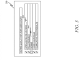
- Figure 3 is a screen capture illustrating a user interface 300, in accordance with an example embodiment.
- the user interface 300 allows the user to define a quality KPI for a user story.
- a user may select to edit parameters for open defects criteria 302 or Sonar 304.
- Sonar 304 is a security tool.
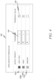
- Figure 4 is a screen capture illustrating a user interface 400, in accordance with an example embodiment.
- the user has selected to edit parameters for open defects criteria 302.
- the user is able to edit parameters for different categories of defect priority 402A, 402B, 402C.
- the user can edit the operator 404 and threshold value 406 for the "very high" defect priority 402A.
- Figure 5 is a screen capture illustrating a user interface 500, in accordance with an example embodiment.
- the user has selected to edit parameters for Sonar 304.
- the user is able to edit parameters for different prepopulated parameters 502A, 502B, 502C.
- the user can edit the threshold value 504 for the "new bugs" prepopulated parameter 502A.
- Figure 6 is a screen capture illustrating a user interface 600, in accordance with an example embodiment.
- the user interface 600 provides an indication of a user story.
- the description of the user story is provided in section 602.
- the current status (here "development is in progress") is depicted at field 604.
- a "review quality KPI" button 306 is provided, but it is grayed out (i.e., non-selectable) until the current status in field 604 changes to "development complete.”.
- Figure 7 is a screen capture illustrating the user interface 600 after development is complete, in accordance with an example embodiment.
- the review quality KPI button 606 is now selectable since the status in field 604 has been changed to development complete. This allows for a straightforward way for a quality lead to review the results of the KPI tests that are associated with this user story.
- Figure 8 is a screen capture illustrating an alternative screen of the user interface 600 after development is complete, in accordance with an example embodiment.
- a visual indicator 800 has been added next to the review quality KPI button 606.
- the visual indicator 800 provides a visual indicator of the category of the KPI review that was automatically performed, as described earlier.
- the results of this review may be classified into green, yellow, or red categories.
- the shade of visual indicator is depicted as being classified as green, meaning that the KPI review has passed (either completely or at least to the point that no user intervention is needed to override it).
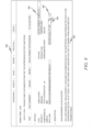
- Figure 9 is a screen capture illustrating a user interface 900 depicting a summary screen of how a green category was assigned to a KPI review of a user story, in accordance with an example embodiment.
- a list of all the tests that passed is presented in green at section 902.
- the user interface 900 is presenting only good news (i.e., that all KPIs have passed), although in certain circumstances it would be possible for the overall KPI review to pass (i.e., be in the green category), even if some individual tests failed, in which case those failed tests could also be presented in this user interface 900 under a different section.
- visual indicator 800 would depict a different color than shown in Figure 8 , namely the red color. In such a case, the user would still be able to click on the review quality KPI button 606 to obtain a summary of how that category was determined.
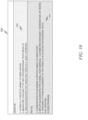
- Figure 10 is a screen capture illustrating a user interface 1000 depicting a summary screen of how a red category was assigned to a KPI review of a user story, in accordance with an example embodiment.
- the list of all tests that passed are presented in green at section 1002, while the list of all tests that failed are presented in red at section 1004.
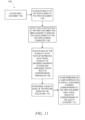
- FIG 11 is a flow diagram illustrating a method 1100 for managing a software project in accordance with an example embodiment.
- a first document is accessed.
- the first document includes a description of a capability need for a feature of a software in development.
- the first document may be, for example, a user story.
- a plurality of KPI tests linked to the first document are accessed.
- Each KPI test includes at least one argument and at least one variable, with each argument having an associated threshold.
- KPI tests may be accessed from a KPI library in a software project management tool and/or may be customized KPI tests specifically for the first document.
- each of the plurality of KPI tests may be evaluated by retrieving data from a plurality of disparate systems and comparing the evaluated KPI tests to the corresponding thresholds.
- a quality level of the feature may be categorized in one of a plurality of different quality categories.
- rendering of a user interface may be caused on a display, the user interface containing a screen corresponding to the first document and a visual indicator corresponding to the quality category in which the quality level of the feature has been categorized.
- Example 1 A system comprising:
- Example 2 The system of Example 1, wherein at least some of the plurality of KPI tests are accessed from a KPI library in a software project management tool.
- Example 3 The system of Example 2, wherein at least some of the plurality of KPI tests have been customized specifically for the first document.
- Example 4 The system of any of Examples 1-3, wherein the user interface further includes a button rendered next to the visual indicator, the button, when selected by a user, causing rendering of a separate screen indicating which of the plurality of KPI tests have passed and which of the plurality of KPI tests have failed.
- Example 5 The system of any of Examples 1-4, wherein at least one of the disparate systems is a bug and issue tracking component.
- Example 6 The system of any of Examples claim 1-5, wherein the operations are performed by a plugin of a software project management tool.
- Example 7 The system of any of Examples 1-6, wherein at least one of the KPI tests is an indication of what percentage of source code corresponding to the feature is covered by at least one unit or integration test.
- Example 8 A method comprising:
- Example 9 The method of Example 8, wherein at least some of the plurality of KPI tests are accessed from a KPI library in a software project management tool.
- Example 10 The method of Example 9, wherein at least some of the plurality of KPI tests have been customized specifically for the first document.
- Example 11 The method of any of Examples 8-10, wherein the user interface further includes a button rendered next to the visual indicator, the button, when selected by a user, causing rendering of a separate screen indicating which of the plurality of KPI tests have passed and which of the plurality of KPI tests have failed.
- Example 12 The method of any of Example 8-11, wherein at least one of the disparate systems is a bug and issue tracking component.
- Example 13 The method of any of Examples 8-12, wherein the operations are performed by a plugin of a software project management tool.
- Example 14 The method of any of Examples 8-13, wherein at least one of the KPI tests is an indication of what percentage of source code corresponding to the feature is covered by at least one unit or integration test.
- Example 15 A non-transitory machine-readable medium storing instructions which, when executed by one or more processors, cause the one or more processors to perform operations comprising:
- Example 16 The non-transitory machine-readable medium of Example 15, wherein at least some of the plurality of KPI tests are accessed from a KPI library in a software project management tool.
- Example 17 The non-transitory machine-readable medium of Example 16, wherein at least some of the plurality of KPI tests have been customized specifically for the first document.
- Example 18 The non-transitory machine-readable medium of any of Examples 15-17, wherein the user interface further includes a button rendered next to the visual indicator, the button, when selected by a user, causing rendering of a separate screen indicating which of the plurality of KPI tests have passed and which of the plurality of KPI tests have failed.
- Example 19 The non-transitory machine-readable medium of Examples 15-18, wherein at least one of the disparate systems is a bug and issue tracking component.
- Example 20 The non-transitory machine-readable medium of Examples 15-19, wherein the operations are performed by a plugin of a software project management tool.
- Figure 12 is a block diagram 1200 illustrating a software architecture 1202, which can be installed on any one or more of the devices described above.
- Figure 12 is merely a non-limiting example of a software architecture, and it will be appreciated that many other architectures can be implemented to facilitate the functionality described herein.
- the software architecture 1202 is implemented by hardware such as a machine 1300 of Figure 13 that comprises processors 1310, memory 1330, and input/output (I/O) components 1350.
- the software architecture 1202 can be conceptualized as a stack of layers where each layer may provide a particular functionality.
- the software architecture 1202 comprises layers such as an operating system 1204, libraries 1206, frameworks 1208, and applications 1210.
- the applications 1210 invoke Application Program Interface (API) calls 1212 through the software stack and receive messages 1214 in response to the API calls 1212, consistent with some embodiments.
- API Application Program Interface
- the operating system 1204 manages hardware resources and provides common services.
- the operating system 1204 comprises, for example, a kernel 1220, services 1222, and drivers 1224.
- the kernel 1220 acts as an abstraction layer between the hardware and the other software layers, consistent with some embodiments.
- the kernel 1220 provides memory management, processor management (e.g., scheduling), component management, networking, and security settings, among other functionality.
- the services 1222 can provide other common services for the other software layers.
- the drivers 1224 are responsible for controlling or interfacing with the underlying hardware.
- the drivers 1224 can comprise display drivers, camera drivers, BLUETOOTH ® or BLUETOOTH ® Low-Energy drivers, flash memory drivers, serial communication drivers (e.g., Universal Serial Bus (USB) drivers), Wi-Fi ® drivers, audio drivers, power management drivers, and so forth.
- USB Universal Serial Bus
- the libraries 1206 provide a low-level common infrastructure utilized by the applications 1210.
- the libraries 1206 can comprise system libraries 1230 (e.g., C standard library) that can provide functions such as memory allocation functions, string manipulation functions, mathematic functions, and the like.
- the libraries 1206 can comprise API libraries 1232 such as media libraries (e.g., libraries to support presentation and manipulation of various media formats such as Moving Picture Experts Group-4 (MPEG4), Advanced Video Coding (H.264 or AVC), Moving Picture Experts Group Layer-3 (MP3), Advanced Audio Coding (AAC), Adaptive Multi-Rate (AMR) audio codec, Joint Photographic Experts Group (JPEG or JPG), or Portable Network Graphics (PNG)), graphics libraries (e.g., an OpenGL framework used to render in two-dimensional (2D) and three-dimensional (3D) in a graphic context on a display), database libraries (e.g., SQLite to provide various relational database functions), web libraries (e.g., WebKit to provide web browsing functionality), and the like.
- the libraries 1206 can also comprise a wide variety of other libraries 1234 to provide many other APIs to the applications 1210.
- the frameworks 1208 provide a high-level common infrastructure that can be utilized by the applications 1210.
- the frameworks 1208 provide various graphical user interface (GUI) functions, high-level resource management, high-level location services, and so forth.
- GUI graphical user interface
- the frameworks 1208 can provide a broad spectrum of other APIs that can be utilized by the applications 1210, some of which may be specific to a particular operating system 1204 or platform.
- the applications 1210 comprise a home application 1250, a contacts application 1252, a browser application 1254, a book reader application 1256, a location application 1258, a media application 1260, a messaging application 1262, a game application 1264, and a broad assortment of other applications, such as a third-party application 1266.
- the applications 1210 can are programs that execute functions defined in the programs.
- Various programming languages can be employed to create one or more of the applications 1210, structured in a variety of manners, such as object-oriented programming languages (e.g., Objective-C, Java, or C++) or procedural programming languages (e.g., C or assembly language).
- the third-party application 1266 may be mobile software running on a mobile operating system such as IOS TM , ANDROID TM , WINDOWS ® Phone, or another mobile operating system.
- the third-party application 1266 can invoke the API calls 1212 provided by the operating system 1204 to facilitate functionality described herein.
- Figure 13 illustrates a diagrammatic representation of a machine 1300 in the form of a computer system within which a set of instructions may be executed for causing the machine 1300 to perform any one or more of the methodologies discussed herein.
- Figure 13 shows a diagrammatic representation of the machine 1300 in the example form of a computer system, within which instructions 1316 (e.g., software, a program, an application, an applet, an app, or other executable code) for causing the machine 1300 to perform any one or more of the methodologies discussed herein may be executed.
- the instructions 1316 may cause the machine 1300 to execute the methods of Figure 11 .
- the instructions 1316 may implement Figures 1-11 and so forth.
- the instructions 1316 transform the general, non-programmed machine 1300 into a particular machine 1300 programmed to carry out the described and illustrated functions in the manner described.
- the machine 1300 operates as a standalone device or may be coupled (e.g., networked) to other machines.
- the machine 1300 may operate in the capacity of a server machine or a client machine in a server-client network environment, or as a peer machine in a peer-to-peer (or distributed) network environment.
- the machine 1300 may comprise, but not be limited to, a server computer, a client computer, a personal computer (PC), a tablet computer, a laptop computer, a netbook, a set-top box (STB), a personal digital assistant (PDA), an entertainment media system, a cellular telephone, a smart phone, a mobile device, a wearable device (e.g., a smart watch), a smart home device (e.g., a smart appliance), other smart devices, a web appliance, a network router, a network switch, a network bridge, or any machine capable of executing the instructions 1316, sequentially or otherwise, that specify actions to be taken by the machine 1300.
- the term "machine” shall also be taken to comprise a collection of machines 1300 that individually or jointly execute the instructions 1316 to perform any one or more of the methodologies discussed herein.
- the machine 1300 may comprise processors 1310, memory 1330, and I/O components 1350, which may be configured to communicate with each other such as via a bus 1302.
- the processors 1310 e.g., a central processing unit (CPU), a reduced instruction set computing (RISC) processor, a complex instruction set computing (CISC) processor, a graphics processing unit (GPU), a digital signal processor (DSP), an application-specific integrated circuit (ASIC), a radio-frequency integrated circuit (RFIC), another processor, or any suitable combination thereof
- the processors 1310 may comprise, for example, a processor 1312 and a processor 1314 that may execute the instructions 1316.
- processor is intended to comprise multi-core processors that may comprise two or more independent processors (sometimes referred to as "cores") that may execute instructions 1316 contemporaneously.
- Figure 13 shows multiple processors 1310, the machine 1300 may comprise a single processor 1312 with a single core, a single processor 1312 with multiple cores (e.g., a multi-core processor 1312), multiple processors 1312, 1314 with a single core, multiple processors 1312, 1314 with multiple cores, or any combination thereof.
- the memory 1330 may comprise a main memory 1332, a static memory 1334, and a storage unit 1336, each accessible to the processors 1310 such as via the bus 1302.
- the main memory 1332, the static memory 1334, and the storage unit 1336 store the instructions 1316 embodying any one or more of the methodologies or functions described herein.
- the instructions 1316 may also reside, completely or partially, within the main memory 1332, within the static memory 1334, within the storage unit 1336, within at least one of the processors 1310 (e.g., within the processor's cache memory), or any suitable combination thereof, during execution thereof by the machine 1300.
- the I/O components 1350 may comprise a wide variety of components to receive input, provide output, produce output, transmit information, exchange information, capture measurements, and so on.
- the specific I/O components 1350 that are comprised in a particular machine will depend on the type of machine. For example, portable machines such as mobile phones will likely comprise a touch input device or other such input mechanisms, while a headless server machine will likely not comprise such a touch input device. It will be appreciated that the I/O components 1350 may comprise many other components that are not shown in Figure 13 .
- the I/O components 1350 are grouped according to functionality merely for simplifying the following discussion, and the grouping is in no way limiting. In various example embodiments, the I/O components 1350 may comprise output components 1352 and input components 1354.
- the output components 1352 may comprise visual components (e.g., a display such as a plasma display panel (PDP), a light-emitting diode (LED) display, a liquid crystal display (LCD), a projector, or a cathode ray tube (CRT)), acoustic components (e.g., speakers), haptic components (e.g., a vibratory motor, resistance mechanisms), other signal generators, and so forth.
- a display such as a plasma display panel (PDP), a light-emitting diode (LED) display, a liquid crystal display (LCD), a projector, or a cathode ray tube (CRT)
- acoustic components e.g., speakers
- haptic components e.g., a vibratory motor, resistance mechanisms
- the input components 1354 may comprise alphanumeric input components (e.g., a keyboard, a touch screen configured to receive alphanumeric input, a photo-optical keyboard, or other alphanumeric input components), point-based input components (e.g., a mouse, a touchpad, a trackball, a joystick, a motion sensor, or another pointing instrument), tactile input components (e.g., a physical button, a touch screen that provides location and/or force of touches or touch gestures, or other tactile input components), audio input components (e.g., a microphone), and the like.
- alphanumeric input components e.g., a keyboard, a touch screen configured to receive alphanumeric input, a photo-optical keyboard, or other alphanumeric input components
- point-based input components e.g., a mouse, a touchpad, a trackball, a joystick, a motion sensor, or another pointing instrument
- tactile input components e.g., a physical button,
- the I/O components 1350 may comprise biometric components 1356, motion components 1358, environmental components 1360, or position components 1362, among a wide array of other components.
- the biometric components 1356 may comprise components to detect expressions (e.g., hand expressions, facial expressions, vocal expressions, body gestures, or eye tracking), measure biosignals (e.g., blood pressure, heart rate, body temperature, perspiration, or brain waves), identify a person (e.g., voice identification, retinal identification, facial identification, fingerprint identification, or electroencephalogram-based identification), and the like.
- the motion components 1358 may comprise acceleration sensor components (e.g., accelerometer), gravitation sensor components, rotation sensor components (e.g., gyroscope), and so forth.
- the environmental components 1360 may comprise, for example, illumination sensor components (e.g., photometer), temperature sensor components (e.g., one or more thermometers that detect ambient temperature), humidity sensor components, pressure sensor components (e.g., barometer), acoustic sensor components (e.g., one or more microphones that detect background noise), proximity sensor components (e.g., infrared sensors that detect nearby objects), gas sensors (e.g., gas detection sensors to detect concentrations of hazardous gases for safety or to measure pollutants in the atmosphere), or other components that may provide indications, measurements, or signals corresponding to a surrounding physical environment.
- illumination sensor components e.g., photometer
- temperature sensor components e.g., one or more thermometers that detect ambient temperature
- humidity sensor components e.g., pressure sensor components (e.g., barometer)
- the position components 1362 may comprise location sensor components (e.g., a Global Positioning System (GPS) receiver component), altitude sensor components (e.g., altimeters or barometers that detect air pressure from which altitude may be derived), orientation sensor components (e.g., magnetometers), and the like.
- location sensor components e.g., a Global Positioning System (GPS) receiver component
- altitude sensor components e.g., altimeters or barometers that detect air pressure from which altitude may be derived
- orientation sensor components e.g., magnetometers
- the I/O components 1350 may comprise communication components 1364 operable to couple the machine 1300 to a network 1380 or devices 1370 via a coupling 1382 and a coupling 1372, respectively.
- the communication components 1364 may comprise a network interface component or another suitable device to interface with the network 1380.
- the communication components 1364 may comprise wired communication components, wireless communication components, cellular communication components, near field communication (NFC) components, Bluetooth ® components (e.g., Bluetooth ® Low Energy), Wi-Fi ® components, and other communication components to provide communication via other modalities.
- the devices 1370 may be another machine or any of a wide variety of peripheral devices (e.g., coupled via a USB).
- the communication components 1364 may detect identifiers or comprise components operable to detect identifiers.
- the communication components 1364 may comprise radio-frequency identification (RFID) tag reader components, NFC smart tag detection components, optical reader components (e.g., an optical sensor to detect one-dimensional bar codes such as Universal Product Code (UPC) bar code, multi-dimensional bar codes such as QR code, Aztec code, Data Matrix, Dataglyph, MaxiCode, PDF417, Ultra Code, UCC RSS-2D bar code, and other optical codes), or acoustic detection components (e.g., microphones to identify tagged audio signals).
- RFID radio-frequency identification
- NFC smart tag detection components e.g., NFC smart tag detection components
- optical reader components e.g., an optical sensor to detect one-dimensional bar codes such as Universal Product Code (UPC) bar code, multi-dimensional bar codes such as QR code, Aztec code, Data Matrix, Dataglyph, MaxiCode, PDF417, Ultra Code, UCC RSS-2D bar code, and other optical codes
- IP Internet Protocol
- Wi-Fi ® Wireless Fidelity
- NFC beacon a variety of information may be derived via the communication components 1364, such as location via Internet Protocol (IP) geolocation, location via Wi-Fi ® signal triangulation, location via detecting an NFC beacon signal that may indicate a particular location, and so forth.
- IP Internet Protocol
- the various memories i.e., 1330, 1332, 1334, and/or memory of the processor(s) 1310 and/or the storage unit 1336 may store one or more sets of instructions 1316 and data structures (e.g., software) embodying or utilized by any one or more of the methodologies or functions described herein.
- These instructions e.g., the instructions 1316
- the processor(s) 1310 when executed by the processor(s) 1310, cause various operations to implement the disclosed embodiments.
- machine-storage medium means the same thing and may be used interchangeably.
- the terms refer to a single or multiple storage devices and/or media (e.g., a centralized or distributed database, and/or associated caches and servers) that store executable instructions and/or data.
- the terms shall accordingly be taken to comprise, but not be limited to, solid-state memories, and optical and magnetic media, including memory internal or external to processors.
- machine-storage media comprising non-volatile memory, including by way of example semiconductor memory devices, e.g., erasable programmable read-only memory (EPROM), electrically erasable programmable read-only memory (EEPROM), field-programmable gate array (FPGA), and flash memory devices; magnetic disks such as internal hard disks and removable disks; magneto-optical disks; and CD-ROM and DVD-ROM disks.
- semiconductor memory devices e.g., erasable programmable read-only memory (EPROM), electrically erasable programmable read-only memory (EEPROM), field-programmable gate array (FPGA), and flash memory devices
- magnetic disks such as internal hard disks and removable disks
- magneto-optical disks magneto-optical disks
- CD-ROM and DVD-ROM disks CD-ROM and DVD-ROM disks.
- machine-storage media specifically exclude carrier waves, modulated data signals, and other such media, at least some of which are covered under the term “signal medium
- one or more portions of the network 1380 may be an ad hoc network, an intranet, an extranet, a virtual private network (VPN), a local-area network (LAN), a wireless LAN (WLAN), a wide-area network (WAN), a wireless WAN (WWAN), a metropolitan-area network (MAN), the Internet, a portion of the Internet, a portion of the public switched telephone network (PSTN), a plain old telephone service (POTS) network, a cellular telephone network, a wireless network, a Wi-Fi ® network, another type of network, or a combination of two or more such networks.
- VPN virtual private network
- LAN local-area network
- WLAN wireless LAN
- WAN wide-area network
- WWAN wireless WAN
- MAN metropolitan-area network
- PSTN public switched telephone network
- POTS plain old telephone service
- the network 1380 or a portion of the network 1380 may comprise a wireless or cellular network
- the coupling 1382 may be a Code Division Multiple Access (CDMA) connection, a Global System for Mobile communications (GSM) connection, or another type of cellular or wireless coupling.
- CDMA Code Division Multiple Access
- GSM Global System for Mobile communications
- the coupling 1382 may implement any of a variety of types of data transfer technology, such as Single Carrier Radio Transmission Technology (1xRTT), Evolution-Data Optimized (EVDO) technology, General Packet Radio Service (GPRS) technology, Enhanced Data rates for GSM Evolution (EDGE) technology, third Generation Partnership Project (3GPP) including 3G, fourth generation wireless (4G) networks, Universal Mobile Telecommunications System (UMTS), High-Speed Packet Access (HSPA), Worldwide Interoperability for Microwave Access (WiMAX), Long-Term Evolution (LTE) standard, others defined by various standard-setting organizations, other long-range protocols, or other data transfer technology.
- 1xRTT Single Carrier Radio Transmission Technology
- GPRS General Packet Radio Service
- EDGE Enhanced Data rates for GSM Evolution
- 3GPP Third Generation Partnership Project
- 4G fourth generation wireless (4G) networks
- Universal Mobile Telecommunications System (UMTS) Universal Mobile Telecommunications System
- HSPA High-Speed Packet Access
- WiMAX Worldwide Interoperability for Micro
- the instructions 1316 may be transmitted or received over the network 1380 using a transmission medium via a network interface device (e.g., a network interface component comprised in the communication components 1364) and utilizing any one of a number of well-known transfer protocols (e.g., Hypertext Transfer Protocol (HTTP)). Similarly, the instructions 1316 may be transmitted or received using a transmission medium via the coupling 1372 (e.g., a peer-to-peer coupling) to the devices 1370.
- a network interface device e.g., a network interface component comprised in the communication components 1364
- HTTP Hypertext Transfer Protocol
- the instructions 1316 may be transmitted or received using a transmission medium via the coupling 1372 (e.g., a peer-to-peer coupling) to the devices 1370.
- the terms "transmission medium” and “signal medium” mean the same thing and may be used interchangeably in this disclosure.
- transmission medium and “signal medium” shall be taken to comprise any intangible medium that is capable of storing, encoding, or carrying the instructions 1316 for execution by the machine 1300, and comprise digital or analog communications signals or other intangible media to facilitate communication of such software.
- transmission medium and “signal medium” shall be taken to comprise any form of modulated data signal, carrier wave, and so forth.
- modulated data signal means a signal that has one or more of its characteristics set or changed in such a manner as to encode information in the signal.
- machine-readable medium means the same thing and may be used interchangeably in this disclosure.
- the terms are defined to comprise both machine-storage media and transmission media.
- the terms comprise both storage devices/media and carrier waves/modulated data signals.
Landscapes
- Engineering & Computer Science (AREA)
- Theoretical Computer Science (AREA)
- General Engineering & Computer Science (AREA)
- Software Systems (AREA)
- Physics & Mathematics (AREA)
- General Physics & Mathematics (AREA)
- Quality & Reliability (AREA)
- Computer Hardware Design (AREA)
- Human Computer Interaction (AREA)
- Data Mining & Analysis (AREA)
- Computer Security & Cryptography (AREA)
- Stored Programmes (AREA)
Abstract
Description
- Software project management systems provide tools to allow developers and other individuals to manage the lifecycle of the development of a software application or software features of an existing application. An example of such a software project management tool is JIRA™ from Atlassian of San Francisco, CA. Software project management systems provide tools for tracking bugs in the applications/features and also for tracking requirements for the applications/features.
- The present disclosure is illustrated by way of example and not limitation in the figures of the accompanying drawings, in which like references indicate similar elements.
-
Figure 1 is a block diagram illustrating a system for managing a software project, in accordance with an example embodiment. -
Figure 2 is a screen capture illustrating a user interface, in accordance with an example embodiment. -
Figure 3 is a screen capture illustrating a user interface, in accordance with another example embodiment. -
Figure 4 is a screen capture illustrating a user interface, in accordance with another example embodiment. -
Figure 5 is a screen capture illustrating a user interface, in accordance with an example embodiment. -
Figure 6 is a screen capture illustrating a user interface, in accordance with another example embodiment. -
Figure 7 is a screen capture illustrating the user interface after development is complete, in accordance with an example embodiment. -
Figure 8 is a screen capture illustrating an alternative screen of the user interface after development is complete, in accordance with an example embodiment. -
Figure 9 is a screen capture illustrating a user interface depicting a summary screen of how a green category was assigned to a Key Performance Index (KPI) review of a user story, in accordance with an example embodiment. -
Figure 10 is a screen capture illustrating a user interface depicting a summary screen of how a red category was assigned to a KPI review of a user story, in accordance with an example embodiment. -
Figure 11 is a flow diagram illustrating a method for managing a software project, in accordance with an example embodiment. -
Figure 12 is a block diagram illustrating an example architecture of software, which can be installed on any one or more of the devices described above. -
Figure 13 illustrates a diagrammatic representation of a machine in the form of a computer system within which a set of instructions may be executed for causing the machine to perform any one or more of the methodologies discussed herein. - The description that follows discusses illustrative systems, methods, techniques, instruction sequences, and computing machine program products. In the following description, for purposes of explanation, numerous specific details are set forth in order to provide an understanding of various example embodiments of the present subject matter. It will be evident, however, to those skilled in the art, that various example embodiments of the present subject matter may be practiced without these specific details.
- Software project management tools allow for the definition of concise representations of a feature in a developing system, described by an induvial who needs this new functionality. These concise representations are known as "user stories." These user stories often use non-technical language to provide context for the development team and their efforts. After reading a user story, the development team knows why they are building the feature, what aspects the feature should have, and what value it creates for the user.
- Typically the development team includes a quality lead, who validates new features prior to them going live or otherwise being made available for use by users. This quality lead is often tasked with determining relevant KPIs for a user story, capturing KPIs across disparate systems, tracking KPIs in a central location on a periodic basis, reviewing all KPIs, and ensuring adherence of the KPIs to defined threshold values.
- In a cloud environment, feature delivery is often performed in a very short development cycle. The existing process is inefficient due to several communication touch-points, resulting in the majority of the quality lead's time being spent on manual interventions, which impacts time-to-market.
- In an example embodiment, an intelligent plug-in is provided for a software project management tool that facilitates automated capture and review of KPIs in order to meet the quality needs of each workstream. This added automation, however, can be technically challenging due to a variety of factors, including the number of disparate systems from which KPIs need to be captured and the desirability of adding customized KPIs.
- The intelligent plug-in accesses a library of KPIs, but also enables a quality lead to define new KPIs and/or customize quality KPIs from the library. The quality lead is also then able to set thresholds for each KPI from within the plug-in. Upon movement of a user story within the software project management tool to a "development completed" or similar state, an automatic review of all defined KPIs for the corresponding user story are reviewed.
- In an example embodiment, a specialized user interface is provided that graphically displays a quality signal for the feature in question based on different levels of confidence that the feature is functioning as desired. More particularly, the different levels of confidence may include a "green" level, indicating that all the relevant KPI thresholds had been met, a "yellow" category, indicating that some threshold percentage of all the relevant KPI thresholds had been met (e.g., 80% of all KPI tests had passed), and a "red" level, indicating that fewer than the threshold percentage of all the relevant KPI thresholds had been met. The corresponding user story is permitted to be moved to the next state in the case of a "green" level and is prevented from being moved to the next state in the case of a "red" level. With the "yellow" level, this level may essentially be considered to be a conditional signoff and permits the quality lead to move the signal state to green upon a manual review.
- Bug tracking within a software project management tool can actually be referred to more broadly as issue tracking. An instance of an issue can include, for example, a bug, task, or backlog item within a feature of a project. A project can be stored, managed, or both stored and managed by a single backend system, or alternatively the project may be spread across multiple backend systems.
- An issue has a lifecycle that is defined by a status. This status may include, for example, open, in-progress, completed, or closed. The lifecycle can be different for specific types of issues or projects. A priority can also be assigned to an issue. The priority indicates how important the issue is, such as critical, blocker, or minor.
- Examples of KPIs that can be used to evaluate features for issues will now be described. One such example is the number of open very high or high defects linked to the user story. Another may be the availability of mandatory unit and/or integration test results. Unit tests are often written by a developer to test portions of a software code. Integration tests may be written by a developer or by others and test integrations of the software code with other software code. Both such tests are often critical to determining validity of the code of a feature, and thus if such tests are not available, then that would be an important factor in deciding whether to validate the code.
- Another example is success rate for linked unit tests. Another example is the number of security defects linked to a user story. Another example is the success rate for all available tests.
- Another example is whether there are any open pull requests (e.g., requests for actions by a software developer that have not yet been completed). Another example is code coverage (e.g., the percentage of lines of code of the feature that are examined by a unit or integration test).
- Each of these KPIs include at least one measurement/calculation, which may also be called an argument and a variable. Each of the arguments may also have a corresponding threshold. The argument is evaluated based on a value for each variable and compared with a threshold. If the output of the argument value of the measurement transgresses the threshold, then the KPI is said to have passed. If not, then the KPI has failed. Thus, for example, in the instance where the KPI is the code coverage test, there is a calculation of what percentage of code lines are covered by a unit or integration test, and then there is a threshold value (e.g., 80%) that this percentage is compared to. In this case, if 80% or more of the code lines are covered by a unit or integration test, then the KPI passes. Otherwise, it fails.
- In an example embodiment, the software project management tool is a web application, and thus users interact with the software project management tool using a web browser. However, this is not mandatory, and embodiments are foreseen where the users interact with the software project management tool via some other means, such as a dedicated software client application, running on a desktop, laptop, or mobile device.
-
Figure 1 is a block diagram illustrating asystem 100 for managing a software project, in accordance with an example embodiment. A softwareproject management tool 102 operates on one or more servers (not pictured), and a user, such as a software developer, interacts with the softwareproject management tool 102 using aweb browser 104. - The software
project management tool 102 includes aweb application framework 106, which defines what happens when a user visits a particular Uniform Resource Locator (URL) in theweb browser 104. Each request from theweb browser 104 may be handled by a web application framework action, which can utilize other objects, such as utility andmanager classes 110, to accomplish a task. - Authentication of communications between the
web browser 104 and the softwareproject management tool 102 may be performed byauthentication system 108. Theauthentication system 108 may be implemented as a servlet filter. A servlet filter is a pluggable object oriented programming component that can be used to intercept and process requests before they are sent to servlets and respond after servlet code is finished. The job of theauthentication system 108 is, given a web request, to associate the request with a particular user. It supports several methods of authentication, including Hypertext Transfer Protocol (HTTP) basic authentication, form-based authentication (i.e., redirect to an internal or external login form), and looking up credentials already stored in the user's session (e.g., cookies set by a single sign-on (SSO) system. - The
authentication system 108 acts to check the credentials of incoming requests and delegates any user-management functions (e.g., looking up a user, checking a user's password is correct) to the softwareproject management tool 102. - On the software
project management tool 102, an identity management andSSO tool 112 stores users and groups in database 114 (which may, in some example embodiments, be a relational database). It also stores group membership indatabase 114. The identity management andSSO tool 112 also authenticates users (e.g., checks to see if user passwords match) and provides an application program interface (API) that allows the management (e.g., creation, deletion) of users, groups, and group memberships. The identity management andSSO tool 112 also allows the softwareproject management tool 102 to connect to external systems to retrieve user/group data and keeps a copy of any external data in thedatabase 114 for faster retrieval, potentially synchronizing in the background. - Property set 116 is a framework that can store a set of properties (key/value pairs) against a particular "entity" with a unique identification. For example, property set 116 may be used to store a user's preferences, in which case the "entity" is a user. Each property has a key and a value and is associated with a single entity.
- The utility and
manager classes 110 contain potentially hundreds of different classes, from utility classes to manager objects. Manager objects typically have one specific goal or topic. Manager objects often use a lot of external dependencies. Manager objects also may be wrapped by a corresponding service class. The idea is that any validation of logic necessary is carried out by the service classes, whereas the manager classes are responsible for actually performing the action. - Included in software
project management tool 102 is a bug andissue tracking component 118 and atask tracking component 120. The bug andissue tracking component 118 acts to track bugs and other issues that occur in a software project. It helps software teams find, record, and track the bugs and issues.Task tracking component 120 tracks tasks (which may or may not include bugs and other issues tracked by the bug and issue tracking component 118) that need to performed for software project completion. - In an example embodiment, a
plugin 122 is provided in the softwareproject management tool 102. Theplugin 122 adds additional functionality not present in the version of the softwareproject management tool 102 that lacks theplugin 122. Specifically, the plugin provides smart functionality that facilitates the automated capture and review of KPIs, including customized KPIs, to meet the quality needs of each workstream. - Included in the
plugin 122 is a KPI library 124. The KPI library 124 includes commonly used KPIs. A customizedKPI creator 126 additionally allows users to define custom KPIs or to modify KPIs in the KPI library to make them custom. Adevelopment tracking component 128 tracks the development status of the software project, such as by interacting with the bug andissue tracking component 118 andtask tracking component 120. When thedevelopment tracking component 128 detects movement of a user story to the "development completed" or a similar state, it notifies aKPI review component 130. TheKPI review component 130 performs an automatic review of all defined KPIs for the user story, whether from the KPI library 124 originally or generated/modified by the customizedKPI creator 126. TheKPI review component 130 classifies the results of this automatic review into one of three categories: green, yellow, or red, as described in more detail above. - An
exception handler component 132 provides a mechanism to handle exception scenarios through special rights. Specifically, certain users, such as the engineering lead or quality lead can make a final decision to move the KPI review state from yellow to green (or even from red to yellow). - Referring back to the
KPI review component 130, this component may further communicate withdisparate systems 134A-134D to calculate the specific KPI values that will be measured against thresholds defined in the KPI library 124 and/or customizedKPI creator 126. Here, for example,disparate system 134A includes a system storing the user story, in which artifacts due to the defects can be detected.Disparate system 134B includes a test repository tool. The test repository tool stores test results. Examples of test repository tools include GTP™ from SAP SE of Walldorf, Germany, X-ray™ from Idera, Inc. of Houston, Texas, and Quick Test Professional (QTP)™ from Hewlett-Packard, Inc. of Palo Alto, CA. -
Disparate system 134C includes a source code quality management tool, such as Sonar™, from SonarSource S.A. of Geneva, Switzerland, which stores results of bugs, especially security bugs, as well as code coverage-related data.Disparate system 134D includes a code change tracking tool such as GitHub™, from Github, Inc. of San Francisco, California, where changes to code are recorded and tracked. This is where items such as open pull requests may be found. - How the
plugin 122 communicates with thedisparate systems 134A-134C to determine the results needed to evaluated the KPIs associated with a particular user story may vary depending upon the type of thedisparate system 134A-134D and the type of the results. - The priority (e.g., very high, high, medium, low) of the defects linked to the user story can be queried using a query in the form: How -> issue in linkedIssues ("UserstoryXXX, "relates to") AND issuetype=Bug AND priority in ("Very High", "High").
- The mandatory availability of Unit and Integration test results may be performed by accessing, for example, a test repository tool. The same tool can be used to evaluate the success rate for linked unit tests.
- For security defects linked to the user story, the folder structure of open issues from the source code quality management tool may be checked to determine if any open issues are specific to a new requirement of the user story.
- The overall success rate for tests in general can be computed by the
plugin 122 itself, using the results pulled from thedisparate systems 134A-134D. - A
user interface component 136 then is able to generate a visual indicator of the categorical quality level of the results of the KPI tests. This visual indicator may include, for example, a color indicative of the category (e.g., green, yellow, or red) and a button that, when selected by a user, launches a screen where a user can see which KPI tests were successful and which failed. -
Figure 2 is a screen capture illustrating auser interface 200, in accordance with an example embodiment. Here, theuser interface 200 provides a project settings screen, where the user can select abutton 202 for creating a custom field at a project level. Upon selection of thebutton 202, a user interface for defining a quality KPI for a user story is displayed. -
Figure 3 is a screen capture illustrating auser interface 300, in accordance with an example embodiment. Here, theuser interface 300 allows the user to define a quality KPI for a user story. For example, a user may select to edit parameters foropen defects criteria 302 orSonar 304.Sonar 304 is a security tool. -
Figure 4 is a screen capture illustrating auser interface 400, in accordance with an example embodiment. Here, the user has selected to edit parameters foropen defects criteria 302. The user is able to edit parameters for different categories ofdefect priority operator 404 andthreshold value 406 for the "very high"defect priority 402A. -
Figure 5 is a screen capture illustrating auser interface 500, in accordance with an example embodiment. Here, the user has selected to edit parameters forSonar 304. The user is able to edit parameters for differentprepopulated parameters threshold value 504 for the "new bugs"prepopulated parameter 502A. -
Figure 6 is a screen capture illustrating auser interface 600, in accordance with an example embodiment. Here, theuser interface 600 provides an indication of a user story. Here, for example, the description of the user story is provided insection 602. The current status (here "development is in progress") is depicted atfield 604. A "review quality KPI" button 306 is provided, but it is grayed out (i.e., non-selectable) until the current status infield 604 changes to "development complete.". -
Figure 7 is a screen capture illustrating theuser interface 600 after development is complete, in accordance with an example embodiment. Here, the reviewquality KPI button 606 is now selectable since the status infield 604 has been changed to development complete. This allows for a straightforward way for a quality lead to review the results of the KPI tests that are associated with this user story. -
Figure 8 is a screen capture illustrating an alternative screen of theuser interface 600 after development is complete, in accordance with an example embodiment. Here, avisual indicator 800 has been added next to the reviewquality KPI button 606. Thevisual indicator 800 provides a visual indicator of the category of the KPI review that was automatically performed, as described earlier. Specifically, in an example embodiment, as described earlier, the results of this review may be classified into green, yellow, or red categories. Here, the shade of visual indicator is depicted as being classified as green, meaning that the KPI review has passed (either completely or at least to the point that no user intervention is needed to override it). It should be noted that while embodiments are described herein where the categories are specifically the colors green, yellow, and red, to resemble those of a traffic light, in other example embodiments, other colors, or even other types of visual indicators entirely, may be used instead. In this case, however, sincevisual indicator 800 reflects a category indicating that the KPI review has passed, then selecting on reviewquality KPI button 606 results in a summary being presented of how that category was determined. -
Figure 9 is a screen capture illustrating auser interface 900 depicting a summary screen of how a green category was assigned to a KPI review of a user story, in accordance with an example embodiment. Here, a list of all the tests that passed is presented in green atsection 902. Here, there are 8 such tests, which just so happens to be all the KPI tests associated with this particular user story. As such, here theuser interface 900 is presenting only good news (i.e., that all KPIs have passed), although in certain circumstances it would be possible for the overall KPI review to pass (i.e., be in the green category), even if some individual tests failed, in which case those failed tests could also be presented in thisuser interface 900 under a different section. - Referring back to
Figure 8 , if it turned out that the result of the KPI review was in the red category, meaning that it has failed, thenvisual indicator 800 would depict a different color than shown inFigure 8 , namely the red color. In such a case, the user would still be able to click on the reviewquality KPI button 606 to obtain a summary of how that category was determined. -
Figure 10 is a screen capture illustrating auser interface 1000 depicting a summary screen of how a red category was assigned to a KPI review of a user story, in accordance with an example embodiment. Here, the list of all tests that passed are presented in green atsection 1002, while the list of all tests that failed are presented in red atsection 1004. -
Figure 11 is a flow diagram illustrating amethod 1100 for managing a software project in accordance with an example embodiment. At operation 1102, a first document is accessed. The first document includes a description of a capability need for a feature of a software in development. The first document may be, for example, a user story. At operation 1104, a plurality of KPI tests linked to the first document are accessed. Each KPI test includes at least one argument and at least one variable, with each argument having an associated threshold. These KPI tests may be accessed from a KPI library in a software project management tool and/or may be customized KPI tests specifically for the first document. - At operation 1106, it may be detected that a status field of the first document has been changed to indicate that development of the feature has been completed. At operation 1108, in response to the detecting, each of the plurality of KPI tests may be evaluated by retrieving data from a plurality of disparate systems and comparing the evaluated KPI tests to the corresponding thresholds. At
operation 1110, based on the evaluating, a quality level of the feature may be categorized in one of a plurality of different quality categories. - At operation 1112, rendering of a user interface may be caused on a display, the user interface containing a screen corresponding to the first document and a visual indicator corresponding to the quality category in which the quality level of the feature has been categorized.
- In view of the disclosure above, various examples are set forth below. It should be noted that one or more features of an example, taken in isolation or combination, should be considered within the disclosure of this application.
- Example 1. A system comprising:
- at least one hardware processor; and
- a non-transitory computer-readable medium storing instructions that, when executed by the at least one hardware processor, cause the at least one hardware processor to perform operations comprising:
- accessing a first document, the first document including a description of a capability need for a feature of a software in development;
- accessing a plurality of key performance indices (KPI) tests linked to the first document, each KPI test including at least one argument and at least one variable, each argument having an associated threshold;
- detecting that a status field of the first document has been changed to indicate that development of the feature has been completed;
- in response to the detecting, evaluating each of the plurality of KPI tests by retrieving data from a plurality of disparate systems and comparing the evaluated KPI tests to the corresponding thresholds;
- based on the evaluating, categorizing a quality level of the feature in one of a plurality of different quality categories; and
- causing rendering of a user interface on a display, the user interface containing a screen corresponding to the first document and a visual indicator corresponding to the quality category in which the quality level of the feature has been categorized.
- Example 2. The system of Example 1, wherein at least some of the plurality of KPI tests are accessed from a KPI library in a software project management tool.
- Example 3. The system of Example 2, wherein at least some of the plurality of KPI tests have been customized specifically for the first document.
- Example 4. The system of any of Examples 1-3, wherein the user interface further includes a button rendered next to the visual indicator, the button, when selected by a user, causing rendering of a separate screen indicating which of the plurality of KPI tests have passed and which of the plurality of KPI tests have failed.
- Example 5. The system of any of Examples 1-4, wherein at least one of the disparate systems is a bug and issue tracking component.
- Example 6. The system of any of Examples claim 1-5, wherein the operations are performed by a plugin of a software project management tool.
- Example 7. The system of any of Examples 1-6, wherein at least one of the KPI tests is an indication of what percentage of source code corresponding to the feature is covered by at least one unit or integration test.
- Example 8. A method comprising:
- accessing a first document, the first document including a description of a capability need for a feature of a software in development;
- accessing a plurality of key performance indices (KPI) tests linked to the first document, each KPI test including at least one argument and at least one variable, each argument having an associated threshold;
- detecting that a status field of the first document has been changed to indicate that development of the feature has been completed;
- in response to the detecting, evaluating each of the plurality of KPI tests by retrieving data from a plurality of disparate systems and comparing the evaluated KPI tests to the corresponding thresholds;
- based on the evaluating, categorizing a quality level of the feature in one of a plurality of different quality categories; and
- causing rendering of a user interface on a display, the user interface containing a screen corresponding to the first document and a visual indicator corresponding to the quality category in which the quality level of the feature has been categorized.
- Example 9. The method of Example 8, wherein at least some of the plurality of KPI tests are accessed from a KPI library in a software project management tool.
- Example 10. The method of Example 9, wherein at least some of the plurality of KPI tests have been customized specifically for the first document.
- Example 11. The method of any of Examples 8-10, wherein the user interface further includes a button rendered next to the visual indicator, the button, when selected by a user, causing rendering of a separate screen indicating which of the plurality of KPI tests have passed and which of the plurality of KPI tests have failed.
- Example 12. The method of any of Example 8-11, wherein at least one of the disparate systems is a bug and issue tracking component.
- Example 13. The method of any of Examples 8-12, wherein the operations are performed by a plugin of a software project management tool.
- Example 14. The method of any of Examples 8-13, wherein at least one of the KPI tests is an indication of what percentage of source code corresponding to the feature is covered by at least one unit or integration test.
- Example 15. A non-transitory machine-readable medium storing instructions which, when executed by one or more processors, cause the one or more processors to perform operations comprising:
- accessing a first document, the first document including a description of a capability need for a feature of a software in development;
- accessing a plurality of key performance indices (KPI) tests linked to the first document, each KPI test including at least one argument and at least one variable, each argument having an associated threshold;
- detecting that a status field of the first document has been changed to indicate that development of the feature has been completed;
- in response to the detecting, evaluating each of the plurality of KPI tests by retrieving data from a plurality of disparate systems and comparing the evaluated KPI tests to the corresponding thresholds;
- based on the evaluating, categorizing a quality level of the feature in one of a plurality of different quality categories; and
- causing rendering of a user interface on a display, the user interface containing a screen corresponding to the first document and a visual indicator corresponding to the quality category in which the quality level of the feature has been categorized.
- Example 16. The non-transitory machine-readable medium of Example 15, wherein at least some of the plurality of KPI tests are accessed from a KPI library in a software project management tool.
- Example 17. The non-transitory machine-readable medium of Example 16, wherein at least some of the plurality of KPI tests have been customized specifically for the first document.
- Example 18. The non-transitory machine-readable medium of any of Examples 15-17, wherein the user interface further includes a button rendered next to the visual indicator, the button, when selected by a user, causing rendering of a separate screen indicating which of the plurality of KPI tests have passed and which of the plurality of KPI tests have failed.
- Example 19. The non-transitory machine-readable medium of Examples 15-18, wherein at least one of the disparate systems is a bug and issue tracking component.
- Example 20. The non-transitory machine-readable medium of Examples 15-19, wherein the operations are performed by a plugin of a software project management tool.
-
Figure 12 is a block diagram 1200 illustrating asoftware architecture 1202, which can be installed on any one or more of the devices described above.Figure 12 is merely a non-limiting example of a software architecture, and it will be appreciated that many other architectures can be implemented to facilitate the functionality described herein. In various embodiments, thesoftware architecture 1202 is implemented by hardware such as amachine 1300 ofFigure 13 that comprisesprocessors 1310,memory 1330, and input/output (I/O)components 1350. In this example architecture, thesoftware architecture 1202 can be conceptualized as a stack of layers where each layer may provide a particular functionality. For example, thesoftware architecture 1202 comprises layers such as anoperating system 1204,libraries 1206,frameworks 1208, andapplications 1210. Operationally, theapplications 1210 invoke Application Program Interface (API) calls 1212 through the software stack and receivemessages 1214 in response to the API calls 1212, consistent with some embodiments. - In various implementations, the
operating system 1204 manages hardware resources and provides common services. Theoperating system 1204 comprises, for example, akernel 1220,services 1222, anddrivers 1224. Thekernel 1220 acts as an abstraction layer between the hardware and the other software layers, consistent with some embodiments. For example, thekernel 1220 provides memory management, processor management (e.g., scheduling), component management, networking, and security settings, among other functionality. Theservices 1222 can provide other common services for the other software layers. Thedrivers 1224 are responsible for controlling or interfacing with the underlying hardware. For instance, thedrivers 1224 can comprise display drivers, camera drivers, BLUETOOTH® or BLUETOOTH® Low-Energy drivers, flash memory drivers, serial communication drivers (e.g., Universal Serial Bus (USB) drivers), Wi-Fi® drivers, audio drivers, power management drivers, and so forth. - In some embodiments, the
libraries 1206 provide a low-level common infrastructure utilized by theapplications 1210. Thelibraries 1206 can comprise system libraries 1230 (e.g., C standard library) that can provide functions such as memory allocation functions, string manipulation functions, mathematic functions, and the like. In addition, thelibraries 1206 can compriseAPI libraries 1232 such as media libraries (e.g., libraries to support presentation and manipulation of various media formats such as Moving Picture Experts Group-4 (MPEG4), Advanced Video Coding (H.264 or AVC), Moving Picture Experts Group Layer-3 (MP3), Advanced Audio Coding (AAC), Adaptive Multi-Rate (AMR) audio codec, Joint Photographic Experts Group (JPEG or JPG), or Portable Network Graphics (PNG)), graphics libraries (e.g., an OpenGL framework used to render in two-dimensional (2D) and three-dimensional (3D) in a graphic context on a display), database libraries (e.g., SQLite to provide various relational database functions), web libraries (e.g., WebKit to provide web browsing functionality), and the like. Thelibraries 1206 can also comprise a wide variety ofother libraries 1234 to provide many other APIs to theapplications 1210. - The
frameworks 1208 provide a high-level common infrastructure that can be utilized by theapplications 1210. For example, theframeworks 1208 provide various graphical user interface (GUI) functions, high-level resource management, high-level location services, and so forth. Theframeworks 1208 can provide a broad spectrum of other APIs that can be utilized by theapplications 1210, some of which may be specific to aparticular operating system 1204 or platform. - In an example embodiment, the
applications 1210 comprise ahome application 1250, acontacts application 1252, abrowser application 1254, abook reader application 1256, alocation application 1258, amedia application 1260, amessaging application 1262, agame application 1264, and a broad assortment of other applications, such as a third-party application 1266. Theapplications 1210 can are programs that execute functions defined in the programs. Various programming languages can be employed to create one or more of theapplications 1210, structured in a variety of manners, such as object-oriented programming languages (e.g., Objective-C, Java, or C++) or procedural programming languages (e.g., C or assembly language). In a specific example, the third-party application 1266 (e.g., an application developed using the ANDROID™ or IOS™ software development kit (SDK) by an entity other than the vendor of the particular platform) may be mobile software running on a mobile operating system such as IOS™, ANDROID™, WINDOWS® Phone, or another mobile operating system. In this example, the third-party application 1266 can invoke the API calls 1212 provided by theoperating system 1204 to facilitate functionality described herein. -
Figure 13 illustrates a diagrammatic representation of amachine 1300 in the form of a computer system within which a set of instructions may be executed for causing themachine 1300 to perform any one or more of the methodologies discussed herein. Specifically,Figure 13 shows a diagrammatic representation of themachine 1300 in the example form of a computer system, within which instructions 1316 (e.g., software, a program, an application, an applet, an app, or other executable code) for causing themachine 1300 to perform any one or more of the methodologies discussed herein may be executed. For example, theinstructions 1316 may cause themachine 1300 to execute the methods ofFigure 11 . Additionally, or alternatively, theinstructions 1316 may implementFigures 1-11 and so forth. Theinstructions 1316 transform the general,non-programmed machine 1300 into aparticular machine 1300 programmed to carry out the described and illustrated functions in the manner described. In alternative embodiments, themachine 1300 operates as a standalone device or may be coupled (e.g., networked) to other machines. In a networked deployment, themachine 1300 may operate in the capacity of a server machine or a client machine in a server-client network environment, or as a peer machine in a peer-to-peer (or distributed) network environment. Themachine 1300 may comprise, but not be limited to, a server computer, a client computer, a personal computer (PC), a tablet computer, a laptop computer, a netbook, a set-top box (STB), a personal digital assistant (PDA), an entertainment media system, a cellular telephone, a smart phone, a mobile device, a wearable device (e.g., a smart watch), a smart home device (e.g., a smart appliance), other smart devices, a web appliance, a network router, a network switch, a network bridge, or any machine capable of executing theinstructions 1316, sequentially or otherwise, that specify actions to be taken by themachine 1300. Further, while only asingle machine 1300 is illustrated, the term "machine" shall also be taken to comprise a collection ofmachines 1300 that individually or jointly execute theinstructions 1316 to perform any one or more of the methodologies discussed herein. - The
machine 1300 may compriseprocessors 1310,memory 1330, and I/O components 1350, which may be configured to communicate with each other such as via abus 1302. In an example embodiment, the processors 1310 (e.g., a central processing unit (CPU), a reduced instruction set computing (RISC) processor, a complex instruction set computing (CISC) processor, a graphics processing unit (GPU), a digital signal processor (DSP), an application-specific integrated circuit (ASIC), a radio-frequency integrated circuit (RFIC), another processor, or any suitable combination thereof) may comprise, for example, aprocessor 1312 and aprocessor 1314 that may execute theinstructions 1316. The term "processor" is intended to comprise multi-core processors that may comprise two or more independent processors (sometimes referred to as "cores") that may executeinstructions 1316 contemporaneously. AlthoughFigure 13 showsmultiple processors 1310, themachine 1300 may comprise asingle processor 1312 with a single core, asingle processor 1312 with multiple cores (e.g., a multi-core processor 1312),multiple processors multiple processors - The
memory 1330 may comprise amain memory 1332, astatic memory 1334, and astorage unit 1336, each accessible to theprocessors 1310 such as via thebus 1302. Themain memory 1332, thestatic memory 1334, and thestorage unit 1336 store theinstructions 1316 embodying any one or more of the methodologies or functions described herein. Theinstructions 1316 may also reside, completely or partially, within themain memory 1332, within thestatic memory 1334, within thestorage unit 1336, within at least one of the processors 1310 (e.g., within the processor's cache memory), or any suitable combination thereof, during execution thereof by themachine 1300. - The I/
O components 1350 may comprise a wide variety of components to receive input, provide output, produce output, transmit information, exchange information, capture measurements, and so on. The specific I/O components 1350 that are comprised in a particular machine will depend on the type of machine. For example, portable machines such as mobile phones will likely comprise a touch input device or other such input mechanisms, while a headless server machine will likely not comprise such a touch input device. It will be appreciated that the I/O components 1350 may comprise many other components that are not shown inFigure 13 . The I/O components 1350 are grouped according to functionality merely for simplifying the following discussion, and the grouping is in no way limiting. In various example embodiments, the I/O components 1350 may compriseoutput components 1352 andinput components 1354. Theoutput components 1352 may comprise visual components (e.g., a display such as a plasma display panel (PDP), a light-emitting diode (LED) display, a liquid crystal display (LCD), a projector, or a cathode ray tube (CRT)), acoustic components (e.g., speakers), haptic components (e.g., a vibratory motor, resistance mechanisms), other signal generators, and so forth. Theinput components 1354 may comprise alphanumeric input components (e.g., a keyboard, a touch screen configured to receive alphanumeric input, a photo-optical keyboard, or other alphanumeric input components), point-based input components (e.g., a mouse, a touchpad, a trackball, a joystick, a motion sensor, or another pointing instrument), tactile input components (e.g., a physical button, a touch screen that provides location and/or force of touches or touch gestures, or other tactile input components), audio input components (e.g., a microphone), and the like. - In further example embodiments, the I/
O components 1350 may comprisebiometric components 1356,motion components 1358,environmental components 1360, orposition components 1362, among a wide array of other components. For example, thebiometric components 1356 may comprise components to detect expressions (e.g., hand expressions, facial expressions, vocal expressions, body gestures, or eye tracking), measure biosignals (e.g., blood pressure, heart rate, body temperature, perspiration, or brain waves), identify a person (e.g., voice identification, retinal identification, facial identification, fingerprint identification, or electroencephalogram-based identification), and the like. Themotion components 1358 may comprise acceleration sensor components (e.g., accelerometer), gravitation sensor components, rotation sensor components (e.g., gyroscope), and so forth. Theenvironmental components 1360 may comprise, for example, illumination sensor components (e.g., photometer), temperature sensor components (e.g., one or more thermometers that detect ambient temperature), humidity sensor components, pressure sensor components (e.g., barometer), acoustic sensor components (e.g., one or more microphones that detect background noise), proximity sensor components (e.g., infrared sensors that detect nearby objects), gas sensors (e.g., gas detection sensors to detect concentrations of hazardous gases for safety or to measure pollutants in the atmosphere), or other components that may provide indications, measurements, or signals corresponding to a surrounding physical environment. Theposition components 1362 may comprise location sensor components (e.g., a Global Positioning System (GPS) receiver component), altitude sensor components (e.g., altimeters or barometers that detect air pressure from which altitude may be derived), orientation sensor components (e.g., magnetometers), and the like. - Communication may be implemented using a wide variety of technologies. The I/
O components 1350 may comprisecommunication components 1364 operable to couple themachine 1300 to anetwork 1380 ordevices 1370 via acoupling 1382 and acoupling 1372, respectively. For example, thecommunication components 1364 may comprise a network interface component or another suitable device to interface with thenetwork 1380. In further examples, thecommunication components 1364 may comprise wired communication components, wireless communication components, cellular communication components, near field communication (NFC) components, Bluetooth® components (e.g., Bluetooth® Low Energy), Wi-Fi® components, and other communication components to provide communication via other modalities. Thedevices 1370 may be another machine or any of a wide variety of peripheral devices (e.g., coupled via a USB). - Moreover, the
communication components 1364 may detect identifiers or comprise components operable to detect identifiers. For example, thecommunication components 1364 may comprise radio-frequency identification (RFID) tag reader components, NFC smart tag detection components, optical reader components (e.g., an optical sensor to detect one-dimensional bar codes such as Universal Product Code (UPC) bar code, multi-dimensional bar codes such as QR code, Aztec code, Data Matrix, Dataglyph, MaxiCode, PDF417, Ultra Code, UCC RSS-2D bar code, and other optical codes), or acoustic detection components (e.g., microphones to identify tagged audio signals). In addition, a variety of information may be derived via thecommunication components 1364, such as location via Internet Protocol (IP) geolocation, location via Wi-Fi® signal triangulation, location via detecting an NFC beacon signal that may indicate a particular location, and so forth. - The various memories (i.e., 1330, 1332, 1334, and/or memory of the processor(s) 1310) and/or the
storage unit 1336 may store one or more sets ofinstructions 1316 and data structures (e.g., software) embodying or utilized by any one or more of the methodologies or functions described herein. These instructions (e.g., the instructions 1316), when executed by the processor(s) 1310, cause various operations to implement the disclosed embodiments. - As used herein, the terms "machine-storage medium," "device-storage medium," and "computer-storage medium" mean the same thing and may be used interchangeably. The terms refer to a single or multiple storage devices and/or media (e.g., a centralized or distributed database, and/or associated caches and servers) that store executable instructions and/or data. The terms shall accordingly be taken to comprise, but not be limited to, solid-state memories, and optical and magnetic media, including memory internal or external to processors. Specific examples of machine-storage media, computer-storage media, and/or device-storage media comprise non-volatile memory, including by way of example semiconductor memory devices, e.g., erasable programmable read-only memory (EPROM), electrically erasable programmable read-only memory (EEPROM), field-programmable gate array (FPGA), and flash memory devices; magnetic disks such as internal hard disks and removable disks; magneto-optical disks; and CD-ROM and DVD-ROM disks. The terms "machine-storage media," "computer-storage media," and "device-storage media" specifically exclude carrier waves, modulated data signals, and other such media, at least some of which are covered under the term "signal medium" discussed below.
- In various example embodiments, one or more portions of the
network 1380 may be an ad hoc network, an intranet, an extranet, a virtual private network (VPN), a local-area network (LAN), a wireless LAN (WLAN), a wide-area network (WAN), a wireless WAN (WWAN), a metropolitan-area network (MAN), the Internet, a portion of the Internet, a portion of the public switched telephone network (PSTN), a plain old telephone service (POTS) network, a cellular telephone network, a wireless network, a Wi-Fi® network, another type of network, or a combination of two or more such networks. For example, thenetwork 1380 or a portion of thenetwork 1380 may comprise a wireless or cellular network, and thecoupling 1382 may be a Code Division Multiple Access (CDMA) connection, a Global System for Mobile communications (GSM) connection, or another type of cellular or wireless coupling. In this example, thecoupling 1382 may implement any of a variety of types of data transfer technology, such as Single Carrier Radio Transmission Technology (1xRTT), Evolution-Data Optimized (EVDO) technology, General Packet Radio Service (GPRS) technology, Enhanced Data rates for GSM Evolution (EDGE) technology, third Generation Partnership Project (3GPP) including 3G, fourth generation wireless (4G) networks, Universal Mobile Telecommunications System (UMTS), High-Speed Packet Access (HSPA), Worldwide Interoperability for Microwave Access (WiMAX), Long-Term Evolution (LTE) standard, others defined by various standard-setting organizations, other long-range protocols, or other data transfer technology. - The
instructions 1316 may be transmitted or received over thenetwork 1380 using a transmission medium via a network interface device (e.g., a network interface component comprised in the communication components 1364) and utilizing any one of a number of well-known transfer protocols (e.g., Hypertext Transfer Protocol (HTTP)). Similarly, theinstructions 1316 may be transmitted or received using a transmission medium via the coupling 1372 (e.g., a peer-to-peer coupling) to thedevices 1370. The terms "transmission medium" and "signal medium" mean the same thing and may be used interchangeably in this disclosure. The terms "transmission medium" and "signal medium" shall be taken to comprise any intangible medium that is capable of storing, encoding, or carrying theinstructions 1316 for execution by themachine 1300, and comprise digital or analog communications signals or other intangible media to facilitate communication of such software. Hence, the terms "transmission medium" and "signal medium" shall be taken to comprise any form of modulated data signal, carrier wave, and so forth. The term "modulated data signal" means a signal that has one or more of its characteristics set or changed in such a manner as to encode information in the signal. - The terms "machine-readable medium," "computer-readable medium," and "device-readable medium" mean the same thing and may be used interchangeably in this disclosure. The terms are defined to comprise both machine-storage media and transmission media. Thus, the terms comprise both storage devices/media and carrier waves/modulated data signals.
Claims (15)
- A system comprising:at least one hardware processor; anda non-transitory computer-readable medium storing instructions that, when executed by the at least one hardware processor, cause the at least one hardware processor to perform operations comprising:accessing a first document, the first document including a description of a capability need for a feature of a software in development;accessing a plurality of key performance indices (KPI) tests linked to the first document, each KPI test including at least one argument and at least one variable, each argument having an associated threshold;detecting that a status field of the first document has been changed to indicate that development of the feature has been completed;in response to the detecting, evaluating each of the plurality of KPI tests by retrieving data from a plurality of disparate systems and comparing the evaluated KPI tests to corresponding thresholds;based on the evaluating, categorizing a quality level of the feature in one of a plurality of different quality categories; andcausing rendering of a user interface on a display, the user interface containing a screen corresponding to the first document and a visual indicator corresponding to the quality category in which the quality level of the feature has been categorized.
- The system of claim 1, wherein at least some of the plurality of KPI tests are accessed from a KPI library in a software project management tool.
- The system of claim 1 or 2, wherein at least some of the plurality of KPI tests have been customized specifically for the first document.
- The system of any one of claims 1 to 3, wherein the user interface further includes a button rendered next to the visual indicator, the button, when selected by a user, causing rendering of a separate screen indicating which of the plurality of KPI tests have passed and which of the plurality of KPI tests have failed.
- The system of any one of claims 1 to 4, wherein at least one of the disparate systems is a bug and issue tracking component.
- The system of any one of claims 1 to 5, wherein the operations are performed by a plugin of a software project management tool.
- The system of any one of claims 1 to 6, wherein at least one of the KPI tests is an indication of what percentage of source code corresponding to the feature is covered by at least one unit or integration test.
- A method comprising:accessing a first document, the first document including a description of a capability need for a feature of a software in development;accessing a plurality of key performance indices (KPI) tests linked to the first document, each KPI test including at least one argument and at least one variable, each argument having an associated threshold;detecting that a status field of the first document has been changed to indicate that development of the feature has been completed;in response to the detecting, evaluating each of the plurality of KPI tests by retrieving data from a plurality of disparate systems and comparing the evaluated KPI tests to corresponding thresholds;based on the evaluating, categorizing a quality level of the feature in one of a plurality of different quality categories; andcausing rendering of a user interface on a display, the user interface containing a screen corresponding to the first document and a visual indicator corresponding to the quality category in which the quality level of the feature has been categorized.
- The method of claim 8, wherein at least some of the plurality of KPI tests are accessed from a KPI library in a software project management tool.
- The method of claim 8 or 9, wherein at least some of the plurality of KPI tests have been customized specifically for the first document.
- The method of any one of claims 8 to 10, wherein the user interface further includes a button rendered next to the visual indicator, the button, when selected by a user, causing rendering of a separate screen indicating which of the plurality of KPI tests have passed and which of the plurality of KPI tests have failed.
- The method of any one of claims 8 to 11, wherein at least one of the disparate systems is a bug and issue tracking component.
- The method of any one of claims 8 to 12, wherein the operations are performed by a plugin of a software project management tool.
- The method of any one of claims 8 to 13, wherein at least one of the KPI tests is an indication of what percentage of source code corresponding to the feature is covered by at least one unit or integration test.
- A non-transitory machine-readable medium storing instructions which, when executed by one or more processors, cause the one or more processors to perform operations according to the method of any one of claims 8 to 14.
Applications Claiming Priority (1)
| Application Number | Priority Date | Filing Date | Title |
|---|---|---|---|
| US17/992,179 US12632251B2 (en) | 2022-11-22 | Software project management tool plug-in |
Publications (1)
| Publication Number | Publication Date |
|---|---|
| EP4375838A1 true EP4375838A1 (en) | 2024-05-29 |
Family
ID=88833806
Family Applications (1)
| Application Number | Title | Priority Date | Filing Date |
|---|---|---|---|
| EP23209376.5A Pending EP4375838A1 (en) | 2022-11-22 | 2023-11-13 | Software project management tool plug-in |
Country Status (2)
| Country | Link |
|---|---|
| EP (1) | EP4375838A1 (en) |
| CN (1) | CN118069198A (en) |
Citations (2)
| Publication number | Priority date | Publication date | Assignee | Title |
|---|---|---|---|---|
| US20190294428A1 (en) * | 2018-03-26 | 2019-09-26 | Ca, Inc. | Automated software release distribution |
| US11429384B1 (en) * | 2021-10-14 | 2022-08-30 | Morgan Stanley Services Group Inc. | System and method for computer development data aggregation |
-
2023
- 2023-11-13 EP EP23209376.5A patent/EP4375838A1/en active Pending
- 2023-11-21 CN CN202311557644.6A patent/CN118069198A/en active Pending
Patent Citations (2)
| Publication number | Priority date | Publication date | Assignee | Title |
|---|---|---|---|---|
| US20190294428A1 (en) * | 2018-03-26 | 2019-09-26 | Ca, Inc. | Automated software release distribution |
| US11429384B1 (en) * | 2021-10-14 | 2022-08-30 | Morgan Stanley Services Group Inc. | System and method for computer development data aggregation |
Also Published As
| Publication number | Publication date |
|---|---|
| CN118069198A (en) | 2024-05-24 |
| US20240168759A1 (en) | 2024-05-23 |
Similar Documents
| Publication | Publication Date | Title |
|---|---|---|
| US20220255890A1 (en) | Automatically selecting an ephemeral message availability | |
| US11561877B2 (en) | Interactive electronic documentation for operational activities | |
| US11681549B2 (en) | Cross-compilation, orchestration, and scheduling for in-memory databases as a service | |
| US20250085934A1 (en) | Programming language to interact with large language model | |
| US12061859B2 (en) | Markdown data content with action binding | |
| US20190268288A1 (en) | Generating conversational nodes for a system function | |
| US11794348B2 (en) | Process assembly line with robotic process automation | |
| EP3920041A1 (en) | Master data profiling | |
| US10897408B2 (en) | Application server programming language running in vsystem | |
| US12041151B2 (en) | Importation of analytics cloud content into custom location in destination tenant | |
| KR20250050098A (en) | Generate context test code | |
| US12632251B2 (en) | Software project management tool plug-in | |
| US20240168759A1 (en) | Software project management tool plug-in | |
| US12159135B2 (en) | Machine learning-based target simulator | |
| US12367130B2 (en) | Test framework via language server protocol | |
| US20240176659A1 (en) | Transparently executing actions within a containerized cloud environment | |
| US12567028B2 (en) | Large line item event processing system | |
| EP4300388A1 (en) | Large line item event processing system | |
| US12619686B2 (en) | Software package sharing to restricted landscapes | |
| US20250335158A1 (en) | Automatic evaluation of artificial intelligence-generated code suggestions | |
| US20260126982A1 (en) | Seamless content transport across data repositories in analytic networks | |
| US20260010712A1 (en) | Context provisioning system for large language model applications | |
| US20260037510A1 (en) | Dynamic analytical model optimizations | |
| US20230132141A1 (en) | Secure operations of cloud landscapes through workflow templates | |
| KR20250085646A (en) | Quantum enhanced optimization |
Legal Events
| Date | Code | Title | Description |
|---|---|---|---|
| PUAI | Public reference made under article 153(3) epc to a published international application that has entered the european phase |
Free format text: ORIGINAL CODE: 0009012 |
|
| STAA | Information on the status of an ep patent application or granted ep patent |
Free format text: STATUS: THE APPLICATION HAS BEEN PUBLISHED |
|
| AK | Designated contracting states |
Kind code of ref document: A1 Designated state(s): AL AT BE BG CH CY CZ DE DK EE ES FI FR GB GR HR HU IE IS IT LI LT LU LV MC ME MK MT NL NO PL PT RO RS SE SI SK SM TR |
|
| STAA | Information on the status of an ep patent application or granted ep patent |
Free format text: STATUS: REQUEST FOR EXAMINATION WAS MADE |
|
| 17P | Request for examination filed |
Effective date: 20241107 |
|
| RBV | Designated contracting states (corrected) |
Designated state(s): AL AT BE BG CH CY CZ DE DK EE ES FI FR GB GR HR HU IE IS IT LI LT LU LV MC ME MK MT NL NO PL PT RO RS SE SI SK SM TR |
|
| STAA | Information on the status of an ep patent application or granted ep patent |
Free format text: STATUS: EXAMINATION IS IN PROGRESS |