EP4375727A1 - Projection apparatus - Google Patents
Projection apparatus Download PDFInfo
- Publication number
- EP4375727A1 EP4375727A1 EP23202268.1A EP23202268A EP4375727A1 EP 4375727 A1 EP4375727 A1 EP 4375727A1 EP 23202268 A EP23202268 A EP 23202268A EP 4375727 A1 EP4375727 A1 EP 4375727A1
- Authority
- EP
- European Patent Office
- Prior art keywords
- scanning
- scanner
- scanning optical
- projection apparatus
- light beam
- Prior art date
- Legal status (The legal status is an assumption and is not a legal conclusion. Google has not performed a legal analysis and makes no representation as to the accuracy of the status listed.)
- Granted
Links
Images








Classifications
-
- G—PHYSICS
- G02—OPTICS
- G02B—OPTICAL ELEMENTS, SYSTEMS OR APPARATUS
- G02B26/00—Optical devices or arrangements for the control of light using movable or deformable optical elements
- G02B26/08—Optical devices or arrangements for the control of light using movable or deformable optical elements for controlling the direction of light
- G02B26/10—Scanning systems
- G02B26/101—Scanning systems with both horizontal and vertical deflecting means, e.g. raster or XY scanners
-
- G—PHYSICS
- G02—OPTICS
- G02B—OPTICAL ELEMENTS, SYSTEMS OR APPARATUS
- G02B26/00—Optical devices or arrangements for the control of light using movable or deformable optical elements
- G02B26/08—Optical devices or arrangements for the control of light using movable or deformable optical elements for controlling the direction of light
- G02B26/10—Scanning systems
- G02B26/105—Scanning systems with one or more pivoting mirrors or galvano-mirrors
-
- G—PHYSICS
- G02—OPTICS
- G02B—OPTICAL ELEMENTS, SYSTEMS OR APPARATUS
- G02B26/00—Optical devices or arrangements for the control of light using movable or deformable optical elements
- G02B26/08—Optical devices or arrangements for the control of light using movable or deformable optical elements for controlling the direction of light
- G02B26/0816—Optical devices or arrangements for the control of light using movable or deformable optical elements for controlling the direction of light by means of one or more reflecting elements
- G02B26/0833—Optical devices or arrangements for the control of light using movable or deformable optical elements for controlling the direction of light by means of one or more reflecting elements the reflecting element being a micromechanical device, e.g. a MEMS mirror, DMD
-
- G—PHYSICS
- G02—OPTICS
- G02B—OPTICAL ELEMENTS, SYSTEMS OR APPARATUS
- G02B26/00—Optical devices or arrangements for the control of light using movable or deformable optical elements
- G02B26/08—Optical devices or arrangements for the control of light using movable or deformable optical elements for controlling the direction of light
- G02B26/10—Scanning systems
- G02B26/12—Scanning systems using multifaceted mirrors
- G02B26/123—Multibeam scanners, e.g. using multiple light sources or beam splitters
Definitions
- Embodiments of the present disclosure relate to a projection apparatus.
- an apparatus to display an attention call to increase safety for a worker or work instructions to inherit a skill of a skilled worker is useful.
- an apparatus projects an image for an attention call onto an inattention region within a visual field of a worker and induces the line of sight of the worker to the inattention region.
- a configuration of the apparatus to enable the worker to recognize the projected image is, for example, a wearable apparatus worn by the user.
- Japanese Unexamined Patent Application Publication No. 2005-202221 discloses a laser scanning projection device incorporated in a wearable apparatus, which scans an object in two-dimensional directions with a laser beam modulated based on an image signal.
- an object of the present disclosure is to provide a projection apparatus that can achieve a wide angle of view.
- a projection apparatus includes: multiple scanning optical systems each including: a light source to emit a light beam; a scanner to deflect the light beam from the light source to form a scanning light beam; a magnifier including: at least one positive lens; and at least one negative lens, to magnify a scanning angle of the scanning light beam from the scanner; and a board having: a mounting surface; and a perpendicular line perpendicular to the mounting surface, the board mounting multiple scanners including the scanner of the multiple scanning optical systems on the mounting surface.
- Multiple scanning light beams have the scanning light beam from the scanner are arranged in rotational symmetry with respect to the perpendicular line with different angles in a plane of the mounting surface of the board, and the multiple scanning optical systems project the multiple scanning light beams to different regions from each other.
- a projection apparatus that achieves a wide angle of view can be provided.
- FIG. 1 is a schematic diagram of a wearable device 1 according to one embodiment of the present disclosure.
- the wearable device 1 is worn on the body of a worker for use.
- the wearable device 1 is attached to the worker's chest in a form of being fixed to a shoulder strap, or is hung from the worker's neck to the breast by using a neck strap.
- a projection apparatus 10 is incorporated in the wearable device 1.
- the projection apparatus 10 projects an image (e.g., a simple graphic for calling attention) on an object (e.g., a structure in a work site or a material placed in a work site) located in an area in which attention is distracted within a range of a visual field of a worker.
- an image e.g., a simple graphic for calling attention
- an object e.g., a structure in a work site or a material placed in a work site located in an area in which attention is distracted within a range of a visual field of a worker.
- FIG. 2 is a perspective view of the projection apparatus 10 according to the present embodiment. As illustrated in FIG. 2 , the projection apparatus 10 includes multiple scanning optical systems 100 (four scanning optical systems in the present embodiment) and a board 200.
- the four scanning optical systems 100 are represented by the scanning optical system 100A, the scanning optical system 100B, the scanning optical system100C, and the scanning optical system100D, respectively.
- the optical axes AXs of the scanning optical systems 100 i.e., 100A, 100B, 100C, and 100D
- the optical axes AXs are represented by the optical axis AX A , the optical axis AX B , the optical axis AXc, and the optical axis AX D , respectively.
- a line indicating the rotationally symmetric axis AX 0 includes a perpendicular line of the mounting surface of the board 200 according to the present embodiment.
- the optical axes AX A to AX D intersect on the rotationally symmetric axis AX 0 and are rotationally arranged with respect to the rotationally symmetric axis AX 0 .
- the scanning optical systems 100A to 100D are arranged at equal intervals around the rotationally symmetric axis AX 0 , for example. In other words, each of the scanning optical systems 100A to 100D is arranged at a position rotated by 90 degrees around the rotationally symmetric axis AX 0 .
- An intersection point of the optical axes AX A , AX B , AXc, and AX D is represented by the intersection point IP.
- the multiple scanning optical systems are arranged around the perpendicular line at an equal interval.
- the optical axis AX of the scanning optical system 100 is an axis passing through the center of each optical element of the scanning optical system 100.
- the projection apparatus further includes multiple magnifiers including the magnifier.
- the multiple magnifiers respectively have multiple optical axes each intersecting the perpendicular line.
- a direction in which the rotationally symmetric axis AX 0 extends is defined as a z-axis direction, and two directions orthogonal to the z-axis direction and orthogonal to each other are defined as an x-axis direction and a y-axis direction, respectively.
- Examples of the rotationally symmetrical axis AX 0 include the perpendicular line.
- the x-axis direction, the y-axis direction and the z-axis direction orthogonal to each other form a left-handed system.
- An x-z plane including the x-axis and the z-axis includes the rotationally symmetric axis AX 0 and the optical axes AX A and AX B .
- a y-z plane including the y-axis and the z-axis includes the rotationally symmetric axis AX 0 , and the optical axes AXc and AX D .
- the scanning optical systems 100A to 100D are arranged so that each of the optical axes AX A to AX D form angles different from each other with respect to the rotationally symmetric axis AX 0 so that the scanning light is projected onto different regions of the object. By combining the partial images projected onto the different regions, one image is formed.
- a projection apparatus includes: multiple scanning optical systems each including: a light sources to emit a light beam; a scanner to deflect the light beam from the light source to form a scanning light beam; a magnifier including: at least one positive lens; and at least one negative lens, to magnify a scanning angle of the scanning light beam from the scanner; and a board having: a mounting surface; and a perpendicular line perpendicular to the mounting surface, the board mounting multiple scanners including the scanner of the multiple scanning optical systems on the mounting surface.
- Multiple scanning light beams have the scanning light beam from the scanner are arranged in rotational symmetry with respect to the perpendicular line with different angles in a plane of the mounting surface of the board, and the multiple scanning optical systems project the multiple scanning light beams to different regions from each other.
- the multiple scanning optical systems respectively include multiple magnifiers including the magnifier, and the multiple scanning optical system are disposed in rotational symmetry with respect to the perpendicular line.
- each part of the scanning optical systems 100A to 100D is arranged so that the scanning optical systems 100A to 100D are arranged at an equal distance from the intersection point IP and each of the scanning light beams is a light beam directed toward the intersection point IP so that the scanning light beam is projected onto different areas of the object.
- the one image includes, for example, at least one calling attention image that is projected onto an inattention area within the visual field of a worker.
- FIG. 3 is a diagram of the scanning optical system 100 according to the present embodiment. As illustrated in FIG. 3 , the scanning optical system 100 includes a light source 110, a mirror 120, a scanner 130, and a magnifier 140 (magnifying optical system).
- the scanning optical system 100 includes a light source 110, a mirror 120, a scanner 130, and a magnifier 140 (magnifying optical system).
- the light source 110 includes a semiconductor laser 112 and a collimator lens 114.
- the light beam emitted from the semiconductor laser 112 is converted into a parallel light beam by the collimator lens 114.
- the semiconductor laser 112 may be replaced by another type of light-emitting element, such as a light-emitting diode (LED).
- LED light-emitting diode
- the collimator lens 114 may convert the light beam incident from the semiconductor laser 112 into a gradually converging light beam instead of a parallel light beam.
- the scanning optical system 100 By designing the scanning optical system 100 so to handle both a parallel light beam and a gradually converging light beam with respect to the light beam emitted from the collimator lens 114, the position adjustment of the collimator lens 114 can be more facilitated.
- the light beam incident on the scanner from the light source includes a parallel light beam or a converging light beam.
- the mirror 120 is disposed on an optical path between the light source 110 and the scanner 130.
- the mirror 120 reflects the parallel light beam incident from the collimator lens 114 toward the scanner 130. In other words, the mirror 120 bends the optical path of the light beam from the light source 110 toward the scanner 130.
- the scanner 130 is a device for deflecting the light beam from the light source 110 to scan, and is, for example, micro-electro-mechanical systems (MEMS) mirror.
- the scanner 130 is mounted on the board 200.
- the scanner 130 oscillates at a high speed in a range of ⁇ n degrees to reflect the parallel light beam or gradually converging light beam from the mirror 120 in a direction corresponding to the deflect angle.
- the deflection angle of the scanner 130 is, for example, ⁇ 3.5 degrees.
- the magnifier 140 is an optical system including at least one positive lens and at least one negative lens, and illustratively includes a positive lens L1 and a negative lens L2.
- the magnifier 140 magnifies the scanning angle of the scanning light beam by the scanner 130.
- the magnifier 140 deflects, for example, the scanning light beam (deflection angle of ⁇ 3.5 degrees) by the scanner 130 in a range of ⁇ 22.5 degrees (i.e., 45 degrees at a full angle). In such a way, since the magnifier 140 magnifies the scanning angle, an image over a wide range that cannot be scanned by the scanner 130 alone can be projected.
- the light beam R 0 is the light beam when the deflection angle of the scanner 130 is 0 degrees.
- the light beam R P is the light beam when the deflection angle of the scanner 130 is +22.5 degrees.
- the light beam R M is the light beam when the deflection angle of the scanner 130 is -22.5 degrees.
- the mirror 120 is disposed at a position further away from the scanner 130 than the positive lens L1 in the z-axis direction in which the rotationally symmetric axis AX 0 extends.
- Examples of the rotationally symmetric axis AX 0 include the direction in which the perpendicular line extends.
- Examples of a lens located close to the scanner 130 in the magnifier 140 include the positive lens L1. More specifically, examples of a lens located closest to the scanner 130 in the magnifier 140 includes the positive lens L1.
- the scanning optical system includes: a mirror in an optical path between the light source and the scanner, and a lens adjacent to the scanner in the magnifier; the mirror bends the light beam from the light source toward the scanner, and the mirror is farther from the scanner than the lens in a direction extending the perpendicular line.
- the degree of freedom in disposing the light source 110 is increased.
- the light source 110 can be arranged in accordance with the overall shape of the projection apparatus 10. As a result, the size of the projection apparatus 10 is advantageously reduced.
- FIG. 4 is a diagram illustrating an arrangement example of the scanning optical system 100.
- a pair of scanning optical systems 100 i.e., the scanning optical systems 100A and 100B
- the scanning optical systems 100A and 100B are disposed so that the optical axes AX A and AX B respectively form different angles with respect to the rotationally symmetric axis AX 0 on the x-z plane.
- FIG. 5 is a diagram of the visual field of a human in visual observation with the naked eye.
- the visual field of a human (observer) under the condition of binocular observation is about 100 degrees from left to right (i.e., 200 degrees in total), 50 degrees upward, and 75 degrees downward (i.e., 125 degrees in total).
- a visual field (stable visual field) that can be reasonably captured as visual information by head movement and eye movement is approximately 80 degrees from left to right and approximately 70 degrees from up to down.
- the region in which the effect of presence at a wide viewing angle is saturated extends approximately 50 degrees leftward and approximately 50 degrees rightward (i.e., 100 degrees in total), which is almost equivalent to the stable visual field, and approximately 35 degrees upward and approximately 50 degrees downward (i.e., 85 degrees in total), that is, an inducing visual field.
- the visual field that can be observed with the highest resolution is at most a region of the center of the visual field with a diameter of about 5 degrees (i.e., discrimination visual field).
- a visual field in which information can be instantly captured by only eye movement that is, an effective visual field, extends a total of approximately 30 degrees horizontally and a total of approximately 20 degrees vertically.
- the projection apparatus 10 has a configuration that can project an image for calling attention to an area above the stable visual field.
- FIG. 6 is a schematic diagram illustrating the projection range of an image by the projection apparatus 10.
- a circle indicated by a broken line indicates a projection range of a partial image by each scanning optical system 100.
- a circle A indicates a projection range of a partial image by the scanning optical system 100A.
- a circle B indicates a projection range of a partial image by the scanning optical system 100B.
- a circle C indicates a projection range of a partial image by the scanning optical system 100C.
- a circle D indicates a projection range of a partial image by the scanning optical system 100D.
- the projection apparatus 10 uses the four scanning optical systems 100A to 100D to project four partial images onto regions different from each other to form one image. As a result, a wide angle of view is achieved. Additionally, the projection areas of the partial images have different projection centers. Further, the projection areas of the partial images may partially overlap each other.
- a wide angle of view can be achieved by keeping no gap between the projection ranges of partial images projected by the scanning optical systems 100A to 100D and reducing the overlapping portion of the projection ranges to be small.
- the scanning optical system 100 projects an image in a range of 45 degrees at a full angle.
- the entire scanning angle (e.g., 45 degrees) of the scanning light beam that passes through the magnifier 140 is assigned to an angle that is twice or more than the angle (e.g., 22.5 degrees) between the optical axis AX and the rotationally symmetric axis AX 0 .
- the scanning optical system 100A is arranged in a direction of -22.5 degrees with respect to the rotationally symmetric axis AX 0 in the x-z plane.
- the scanning optical system 100B is arranged in a direction of +22.5 degrees with respect to the rotationally symmetric axis AX 0 in the x-z plane.
- the scanning optical system 100C is arranged in the y-z plane at an angle of +22.5 degrees with respect to the rotationally symmetric axis AX 0 .
- the scanning optical system 100D is arranged in a direction of -22.5 degrees with respect to the rotationally symmetric axis AX 0 in the y-z plane.
- the projection apparatus 10 can project an image onto an area larger than the effective visual field of a worker.
- the projection apparatus 10 can project an image in a range of 90 degrees at a full angle at the maximum and 70 degrees at a full angle at the minimum, that is, in a region above the stable visual field.
- the scanning optical systems 100A to 100D are rotationally symmetrically arranged around the rotationally symmetric axis AX 0 and have a configuration in which the optical axes AX of the magnifiers 140 intersect one another on the rotationally symmetric axis AX 0 in the back parts of the magnifiers 140, the projection range of the partial image by each scanning optical system 100 is formed at a position around the intersection point IP' including the intersection point IP' (the intersection point between the object to be projected and the rotationally symmetric axis AX 0 ). Since the four circular projection areas overlap with each other at the position including the intersection point IP', the projection areas are arranged with no gap (or approximately no gap).
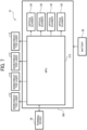
- FIG. 7 is a block diagram illustrating a configuration of a projection apparatus 10 according to an embodiment of the present disclosure.
- a microprocessor unit (MPU) 210 is mounted on the board 200 in addition to the scanner 130 of each scanning optical system 100.
- the semiconductor laser 112, the scanner 130, and the MPU 210 are operated by power supplied from the battery 30.
- the MPU 210 is connected to the terminal device 20 by, for example, wire or wireless.
- the terminal device 20 is, for example, a personal computer (PC), a tablet terminal, or a smartphone.
- the MPU 210 receives projection image data from the terminal device 20.
- the MPU 210 converts the received projection image data into a drive control signal for the semiconductor laser 112 and a drive control signal for the scanner 130, and outputs these drive control signals to the semiconductor laser 112 and the scanner 130 of each scanning optical system 100.
- Each scanning optical system 100 i.e., the semiconductor laser 112 and the scanner 130
- the scanning method by the scanner 130 may be vector scanning or raster scanning.
- the vector scanning for example, a simple graphic can be projected with high brightness.
- the raster scanning a low-luminance image can be projected over a wide area.
- the vector scanning may be employed giving priority to luminance.
- the multiple scanning optical systems 100 are rotationally symmetrically arranged with respect to the rotationally symmetric axis AX 0 , the scanners 130 of the scanning optical systems 100 are concentrated on and disposed in the vicinity of the rotationally symmetric axis AX 0 .
- the scanner 130 of each scanning optical system 100 can be mounted on the board 200 which is a single control board, and the size of the projection apparatus 10 can be reduced.
- FIG. 8 is a diagram illustrating a scanning optical system 100 according to a first modification of the above-described embodiments of the present disclosure.
- FIG. 9 is a diagram illustrating an arrangement example of the scanning optical system 100 according to the first modification of the above-described embodiments of the present disclosure.
- the scanning optical system 100 according to the first modification has the same configuration as that of the scanning optical system 100 according to the above-described embodiments of the present disclosure described above except that an intermediate image I is formed on the optical path.
- the collimator lens 114 converges the light beam incident from the semiconductor laser 112 to form an intermediate image Ion the optical path between the mirror 120 and the scanner 130. As described above, the collimator lens 114 forms the intermediate image I on the optical path between the light source 110 and the scanner 130.
- the intermediate image former include the collimator lens 114.
- the scanning optical system includes an intermediate image former in an optical path between the light source and the scanner to form an intermediate image.
- the power of the magnifier 140 be closer to zero.
- the distance between the intermediate image I and the magnifier 140 on the optical path be larger.
- the intermediate image I is formed on the optical path closer to the light source 110 than to the scanner 130.
- the position adjustment of the collimator lens 114 can be further facilitated.
- FIG. 10 is a perspective view of a projection apparatus 10 according to a second modification of the above-described embodiments of the present disclosure.
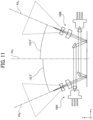
- FIG. 11 is a diagram illustrating an arrangement example of the scanning optical system 100 according to the second modification of the present disclosure.
- the scanning optical system 100 according to the second modification has the same configuration as the scanning optical system 100 according to the embodiments of the present disclosure described above (see FIGS. 2 to 7 ) except that the optical path is different from the optical path of the scanning optical system 100 according to the embodiments of the present disclosure described above.
- the scanning optical systems 100A to 100D are rotationally symmetrically arranged around the rotationally symmetric axis AX 0 , and the optical paths of the light beams from the light sources 110 intersect one another at the front parts of the magnifiers 140.
- the projection apparatus further includes multiple magnifiers including the magnifier, multiple light sources including the light source.
- the multiple magnifiers respectively emit multiple light beams from the multiple light sources, and the multiple light beams from the multiple light sources to the multiple magnifiers intersect with each other.
- the magnifier 140 of the scanning optical system 100A is arranged in a direction of +22.5 degrees with respect to the rotationally symmetric axis AX 0 in the x-z plane.
- the magnifier 140 of the scanning optical system 100B is arranged in a direction of -22.5 degrees with respect to the rotationally symmetric axis AX 0 in the x-z plane.
- the magnifier 140 of the scanning optical system 100C is arranged in the y-z plane at an angle of -22.5 degrees with respect to the rotationally symmetric axis AX 0 .
- the magnifier 140 of the scanning optical system 100D is arranged in a direction of +22.5 degrees with respect to the rotationally symmetric axis AX 0 in the y-z plane.
- FIG. 12 is a schematic diagram illustrating the projection range of an image by the projection apparatus 10 according to the second modification.
- the projection apparatus 10 uses four scanning optical systems 100A to 100D to project four partial images onto regions different from each other to form one image. As a result, a wide angle of view is achieved.
- the scanning optical systems 100A to 100D are rotationally symmetric arranged around the rotationally symmetric axis AX 0 and have a configuration in which the optical paths of light beams from the light sources 110 intersect at the front parts of the magnifiers 140, an image can be projected over a wider range ( FIG. 12 ) than in the above-described embodiments of the present disclosure described above ( FIGS. 2 to 7 ).
- the total scanning angle (e.g., 45 degrees) of the scanning light that has passed through the magnifier 140 is assigned to an angle twice or more of the angle between the optical axis AX and the rotationally symmetric axis AX 0 (e.g., 22.5 degrees) so that a gap is less likely to occur between the projection ranges of the partial images by the scanning optical systems 100.
- a total scanning angle of the scanning light beam via the magnifier has twice or more of an angle between an optical axis of the scanning optical system and the perpendicular line.
- the second modification when one mirror 120 of one scanning optical system 100 and another mirror 120 of another scanning optical system 100, which are a pair of the scanning optical systems and arranged at opposite positions interposing the rotationally symmetric axis AX 0 , are arranged at the same height, vignetting occurs at the mirrors 120 and a proper light beam does not enter the scanner 130.
- the second modification as illustrated in FIG. 11 , in a pair of scanning optical systems 100 arranged to face each other, the light sources 110 and the mirrors 120 are arranged such that the height positions of the light source 110 and the mirror 120 are displaced between the pair of scanning optical systems 100.
- a scanning optical system pair in the projection apparatus, includes a pair of the scanning optical system disposed across the perpendicular line, the pair of the scanning optical system includes a pair of mirrors to bend the light beam from the light source toward the scanner in an optical path between the light source and the scanner, and the pair of mirrors are arranged at a height different from each other from the mounting surface of the board.
- the projection apparatus 10 can be further reduced in size.
- FIG. 13 is a perspective view of a projection apparatus 10 according to a third modification of the above-described embodiments of the present disclosure.
- the scanning optical system 100 according to the third modification has the same configuration as the scanning optical system 100 according to the second modification except that the intermediate image I is formed on the optical path.
- the position adjustment of the collimator lens 114 can be further facilitated as compared with the second modification.
- FIG. 14A is a perspective view of a projection apparatus 10 according to a fourth modification of the above-described embodiments of the present disclosure.
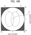
- FIG. 14B is the schematic diagram illustrating the projection range of an image by the projection apparatus according to the fourth modification of the present disclosure.
- the projection apparatus 10 includes a pair of the scanning optical systems 100A and 100B arranged to face each other with the rotationally symmetric axis AX 0 interposed between the pair of scanning optical systems 100.
- the projection apparatus 10 uses a pair of scanning optical systems 100A and 100B to project two partial images forming one image onto regions different from each other. As a result, a wide angle of view is achieved.
- each of the scanning optical systems 100 can project an image in a range of approximately 40 degrees at a full angle horizontally and approximately 90 degrees at a full angle vertically.
- the magnifying power of the magnifier 140 is assigned to a value larger than that in the configuration including four scanning optical systems 100.
- FIG. 15A is a perspective view of a projection apparatus 10 according to a fifth modification of the above-described embodiments of the present disclosure.
- FIG. 15B is the schematic diagram illustrating the projection range of an image by a projection apparatus according to the fifth modification of the present disclosure.
- the projection apparatus 10 includes the three scanning optical systems 100A to 100C rotationally symmetrically arranged around the rotationally symmetric axis AX 0 at 120-degree intervals.
- the projection apparatus 10 uses the three scanning optical systems 100A to 100C to project three partial images to from one image onto regions different from each other. As a result, a wide angle of view is achieved.
- each of the scanning optical systems 100 can project an image in a range of approximately 60 degrees at a full angle horizontally and approximately 60 degrees at a full angle vertically.
- the magnifying power of the magnifier 140 is assigned to a value larger than that in the configuration including four scanning optical systems 100.
- the number of the scanning optical system 100 is not limited to four. The number of the scanning optical system 100 may be five or more.
- the embodiments of the present disclosure are not limited to those described above, and various modifications are possible within the scope of the technical idea of the present disclosure.
- the embodiments of the present disclosure also include contents obtained by appropriately combining the embodiments of the present disclosure explicitly described in the specification or the obvious embodiments.
- the scanning optical systems 100A to 100D intersect on the rotationally symmetric axis AX 0 , but the configuration of the present disclosure is not limited thereto.
- the optical axes AX A to AX D may intersect at a position in the vicinity of the rotational symmetrical axis AX 0 (a position displaced from the rotationally symmetric axis AX 0 ).
- the amount of displacement between the rotationally symmetric axis AX 0 and the intersection point IP may be acceptable as long as the amount of displacement does not affect the projection.
- a projection apparatus includes: multiple scanning optical systems each including: a light source to emit a light beam; a scanner to deflect the light beam from the light source to form a scanning light beam; a magnifier including: at least one positive lens; and at least one negative lens, to magnify a scanning angle of the scanning light beam from the scanner; and a board having: a mounting surface; and a perpendicular line perpendicular to the mounting surface, the board mounting multiple scanners including the scanner of the multiple scanning optical systems on the mounting surface.
- Multiple scanning light beams have the scanning light beam from the scanner are arranged in rotational symmetry with respect to the perpendicular line with different angles in a plane of the mounting surface of the board, and the multiple scanning optical systems project the multiple scanning light beams to different regions from each other.
- the projection apparatus further includes multiple magnifiers including the magnifier, and the multiple magnifiers respectively have multiple optical axes each intersecting the perpendicular line.
- the projection apparatus further includes multiple magnifiers including the magnifier, multiple light sources including the light source.
- the multiple magnifiers respectively emit multiple light beams from the multiple light sources, and the multiple light beams from the multiple light sources to the multiple magnifiers intersect with each other.
- the light beam incident on the scanner from the light source includes a parallel light beam or a converging light beam.
- the scanning optical system includes an intermediate image former in an optical path between the light source and the scanner to form an intermediate image.
- the scanning optical system includes: a mirror in an optical path between the light source and the scanner; and a lens adjacent to the scanner in the magnifier.
- the mirror bends the light beam from the light source toward the scanner, and the mirror is farther from the scanner than the lens in a direction extending the perpendicular line.
- a scanning optical system pair including a pair of scanning optical systems including the scanning optical system disposed across the perpendicular line.
- the pair of the scanning optical systems include a pair of mirrors to bend the light beam from the light source toward the scanner in an optical path between the light source and the scanner, and the pair of mirrors are arranged at a height different from each other from the mounting surface of the board.
- a total scanning angle of the scanning light beam via the magnifier has twice or more of an angle between an optical axis of the scanning optical system and the perpendicular line.
- the multiple scanning optical systems are arranged around the perpendicular line at an equal interval.
- the multiple scanning optical systems respectively include multiple magnifiers including the magnifier, and the multiple scanning optical system are disposed rotational symmetry with respect to the perpendicular line.
- Processing circuitry includes a programmed processor, as a processor includes circuitry.
- a processing circuit also includes devices such as an application specific integrated circuit (ASIC), a digital signal processor (DSP), a field programmable gate array (FPGA), and conventional circuit components arranged to perform the recited functions.
- ASIC application specific integrated circuit
- DSP digital signal processor
- FPGA field programmable gate array
Landscapes
- Physics & Mathematics (AREA)
- General Physics & Mathematics (AREA)
- Optics & Photonics (AREA)
- Mechanical Optical Scanning Systems (AREA)
- Lenses (AREA)
Abstract
Description
- Embodiments of the present disclosure relate to a projection apparatus.
- In a work site, an apparatus to display an attention call to increase safety for a worker or work instructions to inherit a skill of a skilled worker is useful.
- For example, an apparatus projects an image for an attention call onto an inattention region within a visual field of a worker and induces the line of sight of the worker to the inattention region.
- A configuration of the apparatus to enable the worker to recognize the projected image is, for example, a wearable apparatus worn by the user.
- For example,
Japanese Unexamined Patent Application Publication No. 2005-202221 - For such a type of projection apparatus, a wide angle of view is required to project an image into an inattentive area.
- In consideration of the above-described, an object of the present disclosure is to provide a projection apparatus that can achieve a wide angle of view.
- According to an embodiment of the present disclosure, a projection apparatus includes: multiple scanning optical systems each including: a light source to emit a light beam; a scanner to deflect the light beam from the light source to form a scanning light beam; a magnifier including: at least one positive lens; and at least one negative lens, to magnify a scanning angle of the scanning light beam from the scanner; and a board having: a mounting surface; and a perpendicular line perpendicular to the mounting surface, the board mounting multiple scanners including the scanner of the multiple scanning optical systems on the mounting surface. Multiple scanning light beams have the scanning light beam from the scanner are arranged in rotational symmetry with respect to the perpendicular line with different angles in a plane of the mounting surface of the board, and the multiple scanning optical systems project the multiple scanning light beams to different regions from each other.
- According to an embodiment of the present disclosure, a projection apparatus that achieves a wide angle of view can be provided.
- A more complete appreciation of the disclosure and many of the attendant advantages and features thereof can be readily obtained and understood from the following detailed description with reference to the accompanying drawings, wherein:
-
FIG. 1 is a schematic diagram of a wearable device according to one embodiment of the present disclosure; -
FIG. 2 is a perspective view of a projection apparatus according to one embodiment of the present disclosure; -
FIG. 3 is a diagram illustrating a scanning optical system provided with a projection apparatus according to one embodiment of the present disclosure; -
FIG. 4 is a diagram illustrating an arrangement example of a scanning optical system provided with a projection apparatus according to one embodiment of the present disclosure; -
FIG. 5 is a diagram of the visual field of a human in visual observation with the naked eye; -
FIG. 6 is a schematic diagram illustrating the projection range of an image by a projection apparatus according to an embodiment of the present disclosure; -
FIG. 7 is a block diagram illustrating a configuration of a projection apparatus according to one embodiment of the present disclosure; -
FIG. 8 is a diagram illustrating a scanning optical system provided with a projection apparatus according to a first modification of an embodiment of the present disclosure; -
FIG. 9 is a diagram illustrating an arrangement example of a scanning optical system provided with a projection apparatus according to the first modification of an embodiment of the present disclosure; -
FIG. 10 is a perspective view of a projection apparatus according to a second modification of an embodiment of the present disclosure; -
FIG. 11 is a diagram illustrating an arrangement example of a scanning optical system provided with a projection apparatus according to the second modification of an embodiment of the present disclosure; -
FIG. 12 is a schematic diagram illustrating the projection range of an image by a projection apparatus according to the second modification of an embodiment of the present disclosure; -
FIG. 13 is a perspective view of a projection apparatus according to a third modification of an embodiment of the present disclosure; -
FIG. 14A is a perspective view of a projection apparatus according to a fourth modification of an embodiment of the present disclosure; -
FIG. 14B is a schematic diagram illustrating a projection range of an image by a projection apparatus according to a fourth modification of an embodiment of the present disclosure; -
FIG. 15A is a perspective view of a projection apparatus according to a fifth modification of an embodiment of the present disclosure; -
FIG. 15B is a schematic diagram illustrating a projection range of an image by a projection apparatus according to a fifth modification of an embodiment of the present disclosure; and -
FIG. 16 is a top view of a projection apparatus according to one embodiment of the present disclosure. - The accompanying drawings are intended to depict embodiments of the present disclosure and should not be interpreted to limit the scope thereof. The accompanying drawings are not to be considered as drawn to scale unless explicitly noted. Also, identical or similar reference numerals designate identical or similar components throughout the several views.
- In describing embodiments illustrated in the drawings, specific terminology is employed for the sake of clarity. However, the disclosure of this specification is not intended to be limited to the specific terminology so selected and it is to be understood that each specific element includes all technical equivalents that have a similar function, operate in a similar manner, and achieve a similar result.
- Referring now to the drawings, embodiments of the present disclosure are described below. As used herein, the singular forms "a," "an," and "the" are intended to include the plural forms as well, unless the context clearly indicates otherwise.
- In the following description, a projection apparatus according to an embodiment of the present disclosure will be described with reference to the drawings. In the following description, like reference signs denote like elements, and redundant description is appropriately simplified or omitted.
-
FIG. 1 is a schematic diagram of awearable device 1 according to one embodiment of the present disclosure. Thewearable device 1 is worn on the body of a worker for use. - As an example, the
wearable device 1 is attached to the worker's chest in a form of being fixed to a shoulder strap, or is hung from the worker's neck to the breast by using a neck strap. - As illustrated in
FIG. 1 , aprojection apparatus 10 is incorporated in thewearable device 1. Theprojection apparatus 10 projects an image (e.g., a simple graphic for calling attention) on an object (e.g., a structure in a work site or a material placed in a work site) located in an area in which attention is distracted within a range of a visual field of a worker. -
FIG. 2 is a perspective view of theprojection apparatus 10 according to the present embodiment. As illustrated inFIG. 2 , theprojection apparatus 10 includes multiple scanning optical systems 100 (four scanning optical systems in the present embodiment) and aboard 200. - When each of the scanning
optical systems 100 is distinguished from each other to describe, the four scanningoptical systems 100 are represented by the scanningoptical system 100A, the scanningoptical system 100B, the scanning optical system100C, and the scanning optical system100D, respectively. When each of the optical axes AXs of the scanning optical systems 100 (i.e., 100A, 100B, 100C, and 100D) is distinguished from each other to describe, the optical axes AXs are represented by the optical axis AXA, the optical axis AXB, the optical axis AXc, and the optical axis AXD, respectively. - A line indicating the rotationally symmetric axis AX0 includes a perpendicular line of the mounting surface of the
board 200 according to the present embodiment. As illustrated inFIG. 2 , in the scanningoptical systems 100A to 100D, the optical axes AXA to AXD intersect on the rotationally symmetric axis AX0 and are rotationally arranged with respect to the rotationally symmetric axis AX0. The scanningoptical systems 100A to 100D are arranged at equal intervals around the rotationally symmetric axis AX0, for example. In other words, each of the scanningoptical systems 100A to 100D is arranged at a position rotated by 90 degrees around the rotationally symmetric axis AX0. An intersection point of the optical axes AXA, AXB, AXc, and AXD is represented by the intersection point IP. - In at least some embodiments, in the projection apparatus, the multiple scanning optical systems are arranged around the perpendicular line at an equal interval.
- The optical axis AX of the scanning
optical system 100 is an axis passing through the center of each optical element of the scanningoptical system 100. - In at least some embodiments, the projection apparatus, further includes multiple magnifiers including the magnifier. The multiple magnifiers respectively have multiple optical axes each intersecting the perpendicular line.
- In the following description, a direction in which the rotationally symmetric axis AX0 extends is defined as a z-axis direction, and two directions orthogonal to the z-axis direction and orthogonal to each other are defined as an x-axis direction and a y-axis direction, respectively. Examples of the rotationally symmetrical axis AX0 include the perpendicular line. The x-axis direction, the y-axis direction and the z-axis direction orthogonal to each other form a left-handed system.
- An x-z plane including the x-axis and the z-axis includes the rotationally symmetric axis AX0 and the optical axes AXA and AXB. A y-z plane including the y-axis and the z-axis includes the rotationally symmetric axis AX0, and the optical axes AXc and AXD.
- The scanning
optical systems 100A to 100D are arranged so that each of the optical axes AXA to AXD form angles different from each other with respect to the rotationally symmetric axis AX0 so that the scanning light is projected onto different regions of the object. By combining the partial images projected onto the different regions, one image is formed. - In other words, since one image is projected onto a wide area that cannot be projected by the single scanning
optical system 100, a wide angle of view can be achieved. - In at least some embodiments, a projection apparatus includes: multiple scanning optical systems each including: a light sources to emit a light beam; a scanner to deflect the light beam from the light source to form a scanning light beam; a magnifier including: at least one positive lens; and at least one negative lens, to magnify a scanning angle of the scanning light beam from the scanner; and a board having: a mounting surface; and a perpendicular line perpendicular to the mounting surface, the board mounting multiple scanners including the scanner of the multiple scanning optical systems on the mounting surface. Multiple scanning light beams have the scanning light beam from the scanner are arranged in rotational symmetry with respect to the perpendicular line with different angles in a plane of the mounting surface of the board, and the multiple scanning optical systems project the multiple scanning light beams to different regions from each other.
- In at least some embodiments, in the projection apparatus, the multiple scanning optical systems respectively include multiple magnifiers including the magnifier, and the multiple scanning optical system are disposed in rotational symmetry with respect to the perpendicular line.
- Additionally, each part of the scanning
optical systems 100A to 100D is arranged so that the scanningoptical systems 100A to 100D are arranged at an equal distance from the intersection point IP and each of the scanning light beams is a light beam directed toward the intersection point IP so that the scanning light beam is projected onto different areas of the object. - The one image includes, for example, at least one calling attention image that is projected onto an inattention area within the visual field of a worker.
-
FIG. 3 is a diagram of the scanningoptical system 100 according to the present embodiment. As illustrated inFIG. 3 , the scanningoptical system 100 includes alight source 110, amirror 120, ascanner 130, and a magnifier 140 (magnifying optical system). - The
light source 110 includes asemiconductor laser 112 and acollimator lens 114. The light beam emitted from thesemiconductor laser 112 is converted into a parallel light beam by thecollimator lens 114. - The
semiconductor laser 112 may be replaced by another type of light-emitting element, such as a light-emitting diode (LED). - The
collimator lens 114 may convert the light beam incident from thesemiconductor laser 112 into a gradually converging light beam instead of a parallel light beam. By designing the scanningoptical system 100 so to handle both a parallel light beam and a gradually converging light beam with respect to the light beam emitted from thecollimator lens 114, the position adjustment of thecollimator lens 114 can be more facilitated. - In at least some embodiments, in the projection apparatus, the light beam incident on the scanner from the light source includes a parallel light beam or a converging light beam.
- The
mirror 120 is disposed on an optical path between thelight source 110 and thescanner 130. Themirror 120 reflects the parallel light beam incident from thecollimator lens 114 toward thescanner 130. In other words, themirror 120 bends the optical path of the light beam from thelight source 110 toward thescanner 130. - The
scanner 130 is a device for deflecting the light beam from thelight source 110 to scan, and is, for example, micro-electro-mechanical systems (MEMS) mirror. Thescanner 130 is mounted on theboard 200. Thescanner 130 oscillates at a high speed in a range of ±n degrees to reflect the parallel light beam or gradually converging light beam from themirror 120 in a direction corresponding to the deflect angle. The deflection angle of thescanner 130 is, for example, ±3.5 degrees. - The
magnifier 140 is an optical system including at least one positive lens and at least one negative lens, and illustratively includes a positive lens L1 and a negative lens L2. - The
magnifier 140 magnifies the scanning angle of the scanning light beam by thescanner 130. Themagnifier 140 deflects, for example, the scanning light beam (deflection angle of ±3.5 degrees) by thescanner 130 in a range of ±22.5 degrees (i.e., 45 degrees at a full angle). In such a way, since themagnifier 140 magnifies the scanning angle, an image over a wide range that cannot be scanned by thescanner 130 alone can be projected. - In
FIG. 3 , the light beam R0 is the light beam when the deflection angle of thescanner 130 is 0 degrees. The light beam RP is the light beam when the deflection angle of thescanner 130 is +22.5 degrees. The light beam RM is the light beam when the deflection angle of thescanner 130 is -22.5 degrees. - The
mirror 120 is disposed at a position further away from thescanner 130 than the positive lens L1 in the z-axis direction in which the rotationally symmetric axis AX0 extends. Examples of the rotationally symmetric axis AX0include the direction in which the perpendicular line extends. Examples of a lens located close to thescanner 130 in themagnifier 140 include the positive lens L1. More specifically, examples of a lens located closest to thescanner 130 in themagnifier 140 includes the positive lens L1. By disposing themirror 120 as described above, elements of the scanningoptical system 100 can be consolidated and disposed in a limited space. As a result, the size of theprojection apparatus 10 can be reduced to increase the wearable property of thewearable device 1. - In at least some embodiments, in the projection apparatus, the scanning optical system includes: a mirror in an optical path between the light source and the scanner, and a lens adjacent to the scanner in the magnifier; the mirror bends the light beam from the light source toward the scanner, and the mirror is farther from the scanner than the lens in a direction extending the perpendicular line.
- Further, by disposing the
mirror 120 on the optical path between thelight source 110 and thescanner 130, the degree of freedom in disposing thelight source 110 is increased. For example, thelight source 110 can be arranged in accordance with the overall shape of theprojection apparatus 10. As a result, the size of theprojection apparatus 10 is advantageously reduced. -
FIG. 4 is a diagram illustrating an arrangement example of the scanningoptical system 100. InFIG. 4 , a pair of scanning optical systems 100 (i.e., the scanningoptical systems optical systems 100. As illustrated inFIG. 4 , the scanningoptical systems -
FIG. 5 is a diagram of the visual field of a human in visual observation with the naked eye. - It is said that the visual field of a human (observer) under the condition of binocular observation is about 100 degrees from left to right (i.e., 200 degrees in total), 50 degrees upward, and 75 degrees downward (i.e., 125 degrees in total). Within this visual field, a visual field (stable visual field) that can be reasonably captured as visual information by head movement and eye movement is approximately 80 degrees from left to right and approximately 70 degrees from up to down. In addition, with respect to such a visual field of a human, the region in which the effect of presence at a wide viewing angle is saturated extends approximately 50 degrees leftward and approximately 50 degrees rightward (i.e., 100 degrees in total), which is almost equivalent to the stable visual field, and approximately 35 degrees upward and approximately 50 degrees downward (i.e., 85 degrees in total), that is, an inducing visual field.
- As described above, although the visual field of a human is greatly expanded, the visual field that can be observed with the highest resolution is at most a region of the center of the visual field with a diameter of about 5 degrees (i.e., discrimination visual field). A visual field in which information can be instantly captured by only eye movement, that is, an effective visual field, extends a total of approximately 30 degrees horizontally and a total of approximately 20 degrees vertically.
- For example, danger can be recognized within the range of the effective visual field by a human, and if there is an object to be aware of in the region outside the effective visual field, the object cannot be often aware of by a human. In consideration of such circumstances, the
projection apparatus 10 according to the present embodiment has a configuration that can project an image for calling attention to an area above the stable visual field. -
FIG. 6 is a schematic diagram illustrating the projection range of an image by theprojection apparatus 10. InFIG. 6 , a circle indicated by a broken line indicates a projection range of a partial image by each scanningoptical system 100. A circle A indicates a projection range of a partial image by the scanningoptical system 100A. A circle B indicates a projection range of a partial image by the scanningoptical system 100B. A circle C indicates a projection range of a partial image by the scanningoptical system 100C. A circle D indicates a projection range of a partial image by the scanningoptical system 100D. - As illustrated in
FIG. 6 , theprojection apparatus 10 uses the four scanningoptical systems 100A to 100D to project four partial images onto regions different from each other to form one image. As a result, a wide angle of view is achieved. Additionally, the projection areas of the partial images have different projection centers. Further, the projection areas of the partial images may partially overlap each other. - As found from
FIG. 6 , a wide angle of view can be achieved by keeping no gap between the projection ranges of partial images projected by the scanningoptical systems 100A to 100D and reducing the overlapping portion of the projection ranges to be small. - The scanning
optical system 100 projects an image in a range of 45 degrees at a full angle. - In such a case, by changing the direction of each of the opposing optical systems by 45 degrees, there is no gap between the projection ranges of the partial images by the scanning
optical systems 100, and the overlapping portion of the projection ranges is reduced to be small. - Thus, in order not to generate a gap between projection ranges of partial images by the respective scanning
optical systems 100, the entire scanning angle (e.g., 45 degrees) of the scanning light beam that passes through themagnifier 140 is assigned to an angle that is twice or more than the angle (e.g., 22.5 degrees) between the optical axis AX and the rotationally symmetric axis AX0. - As illustrated in
FIG. 4 , the scanningoptical system 100A is arranged in a direction of -22.5 degrees with respect to the rotationally symmetric axis AX0 in the x-z plane. The scanningoptical system 100B is arranged in a direction of +22.5 degrees with respect to the rotationally symmetric axis AX0 in the x-z plane. Similarly, the scanningoptical system 100C is arranged in the y-z plane at an angle of +22.5 degrees with respect to the rotationally symmetric axis AX0. The scanningoptical system 100D is arranged in a direction of -22.5 degrees with respect to the rotationally symmetric axis AX0 in the y-z plane. - As a result, the
projection apparatus 10 according to the present embodiment can project an image onto an area larger than the effective visual field of a worker. As an example, theprojection apparatus 10 can project an image in a range of 90 degrees at a full angle at the maximum and 70 degrees at a full angle at the minimum, that is, in a region above the stable visual field. - Additionally, in the present embodiment, since the scanning
optical systems 100A to 100D are rotationally symmetrically arranged around the rotationally symmetric axis AX0 and have a configuration in which the optical axes AX of themagnifiers 140 intersect one another on the rotationally symmetric axis AX0 in the back parts of themagnifiers 140, the projection range of the partial image by each scanningoptical system 100 is formed at a position around the intersection point IP' including the intersection point IP' (the intersection point between the object to be projected and the rotationally symmetric axis AX0). Since the four circular projection areas overlap with each other at the position including the intersection point IP', the projection areas are arranged with no gap (or approximately no gap). -
FIG. 7 is a block diagram illustrating a configuration of aprojection apparatus 10 according to an embodiment of the present disclosure. As illustrated inFIG. 7 , a microprocessor unit (MPU) 210 is mounted on theboard 200 in addition to thescanner 130 of each scanningoptical system 100. Thesemiconductor laser 112, thescanner 130, and theMPU 210 are operated by power supplied from thebattery 30. - The
MPU 210 is connected to the terminal device 20 by, for example, wire or wireless. The terminal device 20 is, for example, a personal computer (PC), a tablet terminal, or a smartphone. - The
MPU 210 receives projection image data from the terminal device 20. TheMPU 210 converts the received projection image data into a drive control signal for thesemiconductor laser 112 and a drive control signal for thescanner 130, and outputs these drive control signals to thesemiconductor laser 112 and thescanner 130 of each scanningoptical system 100. Each scanning optical system 100 (i.e., thesemiconductor laser 112 and the scanner 130) operates independently according to a partial image to be projected based on an input drive control signal. By combining partial images obtained by the scanningoptical systems 100, one image with a wide angle of view is projected onto an object. - The scanning method by the
scanner 130 may be vector scanning or raster scanning. In the case of the vector scanning, for example, a simple graphic can be projected with high brightness. In the case of the raster scanning, a low-luminance image can be projected over a wide area. In the case of calling attention at a work site, for example, the vector scanning may be employed giving priority to luminance. - In the present embodiment, since the multiple scanning
optical systems 100 are rotationally symmetrically arranged with respect to the rotationally symmetric axis AX0, thescanners 130 of the scanningoptical systems 100 are concentrated on and disposed in the vicinity of the rotationally symmetric axis AX0. Thus, thescanner 130 of each scanningoptical system 100 can be mounted on theboard 200 which is a single control board, and the size of theprojection apparatus 10 can be reduced. -
FIG. 8 is a diagram illustrating a scanningoptical system 100 according to a first modification of the above-described embodiments of the present disclosure.FIG. 9 is a diagram illustrating an arrangement example of the scanningoptical system 100 according to the first modification of the above-described embodiments of the present disclosure. The scanningoptical system 100 according to the first modification has the same configuration as that of the scanningoptical system 100 according to the above-described embodiments of the present disclosure described above except that an intermediate image I is formed on the optical path. - In the first modification, the
collimator lens 114 converges the light beam incident from thesemiconductor laser 112 to form an intermediate image Ion the optical path between themirror 120 and thescanner 130. As described above, thecollimator lens 114 forms the intermediate image I on the optical path between thelight source 110 and thescanner 130. Examples of the intermediate image former include thecollimator lens 114. - In at least some embodiments, in the projection apparatus, the scanning optical system includes an intermediate image former in an optical path between the light source and the scanner to form an intermediate image.
- It is preferable that the power of the
magnifier 140 be closer to zero. Thus, it is preferable that the distance between the intermediate image I and themagnifier 140 on the optical path be larger. In the first modification, the intermediate image I is formed on the optical path closer to thelight source 110 than to thescanner 130. - By adopting a configuration in which the intermediate image I is formed on the optical path between the
light source 110 and thescanner 130, the position adjustment of thecollimator lens 114 can be further facilitated. -
FIG. 10 is a perspective view of aprojection apparatus 10 according to a second modification of the above-described embodiments of the present disclosure.FIG. 11 is a diagram illustrating an arrangement example of the scanningoptical system 100 according to the second modification of the present disclosure. The scanningoptical system 100 according to the second modification has the same configuration as the scanningoptical system 100 according to the embodiments of the present disclosure described above (seeFIGS. 2 to 7 ) except that the optical path is different from the optical path of the scanningoptical system 100 according to the embodiments of the present disclosure described above. - As illustrated in
FIGS. 10 and11 , in the second modification, the scanningoptical systems 100A to 100D are rotationally symmetrically arranged around the rotationally symmetric axis AX0, and the optical paths of the light beams from thelight sources 110 intersect one another at the front parts of themagnifiers 140. - In at least some embodiments, the projection apparatus, further includes multiple magnifiers including the magnifier, multiple light sources including the light source. The multiple magnifiers respectively emit multiple light beams from the multiple light sources, and the multiple light beams from the multiple light sources to the multiple magnifiers intersect with each other.
- Further, as illustrated in
FIG. 11 , themagnifier 140 of the scanningoptical system 100A is arranged in a direction of +22.5 degrees with respect to the rotationally symmetric axis AX0 in the x-z plane. Themagnifier 140 of the scanningoptical system 100B is arranged in a direction of -22.5 degrees with respect to the rotationally symmetric axis AX0 in the x-z plane. Similarly, themagnifier 140 of the scanningoptical system 100C is arranged in the y-z plane at an angle of -22.5 degrees with respect to the rotationally symmetric axis AX0. Themagnifier 140 of the scanningoptical system 100D is arranged in a direction of +22.5 degrees with respect to the rotationally symmetric axis AX0 in the y-z plane. -
FIG. 12 is a schematic diagram illustrating the projection range of an image by theprojection apparatus 10 according to the second modification. - As illustrated in
FIG. 12 , also in the second modification, theprojection apparatus 10 uses four scanningoptical systems 100A to 100D to project four partial images onto regions different from each other to form one image. As a result, a wide angle of view is achieved. - In the second modification, since the scanning
optical systems 100A to 100D are rotationally symmetric arranged around the rotationally symmetric axis AX0 and have a configuration in which the optical paths of light beams from thelight sources 110 intersect at the front parts of themagnifiers 140, an image can be projected over a wider range (FIG. 12 ) than in the above-described embodiments of the present disclosure described above (FIGS. 2 to 7 ). - Additionally, the total scanning angle (e.g., 45 degrees) of the scanning light that has passed through the
magnifier 140 is assigned to an angle twice or more of the angle between the optical axis AX and the rotationally symmetric axis AX0 (e.g., 22.5 degrees) so that a gap is less likely to occur between the projection ranges of the partial images by the scanningoptical systems 100. - In at least some embodiments, in the projection apparatus, a total scanning angle of the scanning light beam via the magnifier has twice or more of an angle between an optical axis of the scanning optical system and the perpendicular line.
- In the second modification, when one
mirror 120 of one scanningoptical system 100 and anothermirror 120 of another scanningoptical system 100, which are a pair of the scanning optical systems and arranged at opposite positions interposing the rotationally symmetric axis AX0, are arranged at the same height, vignetting occurs at themirrors 120 and a proper light beam does not enter thescanner 130. In order to avoid such vignetting, in the second modification, as illustrated inFIG. 11 , in a pair of scanningoptical systems 100 arranged to face each other, thelight sources 110 and themirrors 120 are arranged such that the height positions of thelight source 110 and themirror 120 are displaced between the pair of scanningoptical systems 100. - In at least some embodiments, in the projection apparatus, a scanning optical system pair, includes a pair of the scanning optical system disposed across the perpendicular line, the pair of the scanning optical system includes a pair of mirrors to bend the light beam from the light source toward the scanner in an optical path between the light source and the scanner, and the pair of mirrors are arranged at a height different from each other from the mounting surface of the board.
- By displacing the height positions of the
light source 110 and themirror 120, elements of the scanningoptical system 100 can be disposed in a reduced space as compared with the embodiments of the present disclosure described above (seeFIGS. 2 to 7 ). Thus, theprojection apparatus 10 can be further reduced in size. -
FIG. 13 is a perspective view of aprojection apparatus 10 according to a third modification of the above-described embodiments of the present disclosure. The scanningoptical system 100 according to the third modification has the same configuration as the scanningoptical system 100 according to the second modification except that the intermediate image I is formed on the optical path. - By adopting the configuration in which the intermediate image I is formed on the optical path between the
light source 110 and thescanner 130, the position adjustment of thecollimator lens 114 can be further facilitated as compared with the second modification. - The number of the scanning
optical system 100 is not limited to four.FIG. 14A is a perspective view of aprojection apparatus 10 according to a fourth modification of the above-described embodiments of the present disclosure.FIG. 14B is the schematic diagram illustrating the projection range of an image by the projection apparatus according to the fourth modification of the present disclosure. - As illustrated in
FIG. 14A , theprojection apparatus 10 according to the fourth modification includes a pair of the scanningoptical systems optical systems 100. In the fourth modification, as illustrated inFIG. 14B , theprojection apparatus 10 uses a pair of scanningoptical systems - In order to achieve a projection range of 70 degrees at a full angle for the
projection apparatus 10, each of the scanningoptical systems 100 can project an image in a range of approximately 40 degrees at a full angle horizontally and approximately 90 degrees at a full angle vertically. Thus, in the fourth modification, the magnifying power of themagnifier 140 is assigned to a value larger than that in the configuration including four scanningoptical systems 100. -
FIG. 15A is a perspective view of aprojection apparatus 10 according to a fifth modification of the above-described embodiments of the present disclosure.FIG. 15B is the schematic diagram illustrating the projection range of an image by a projection apparatus according to the fifth modification of the present disclosure. - As illustrated in
FIG. 15A , theprojection apparatus 10 according to the fifth modification includes the three scanningoptical systems 100A to 100C rotationally symmetrically arranged around the rotationally symmetric axis AX0 at 120-degree intervals. In the fifth modification, as illustrated inFIG. 15B , theprojection apparatus 10 uses the three scanningoptical systems 100A to 100C to project three partial images to from one image onto regions different from each other. As a result, a wide angle of view is achieved. - In order to achieve a projection range of 70 degrees at a full angle for the
projection apparatus 10, each of the scanningoptical systems 100 can project an image in a range of approximately 60 degrees at a full angle horizontally and approximately 60 degrees at a full angle vertically. Thus, in the fifth modification, the magnifying power of themagnifier 140 is assigned to a value larger than that in the configuration including four scanningoptical systems 100. - The number of the scanning
optical system 100 is not limited to four. The number of the scanningoptical system 100 may be five or more. - The above is a description of exemplary embodiments of the present disclosure.
- The embodiments of the present disclosure are not limited to those described above, and various modifications are possible within the scope of the technical idea of the present disclosure. For example, the embodiments of the present disclosure also include contents obtained by appropriately combining the embodiments of the present disclosure explicitly described in the specification or the obvious embodiments.
- For example, in
FIG. 2 , in the optical axes AXA to AXD, the scanningoptical systems 100A to 100D intersect on the rotationally symmetric axis AX0, but the configuration of the present disclosure is not limited thereto. As an example, the optical axes AXA to AXD may intersect at a position in the vicinity of the rotational symmetrical axis AX0 (a position displaced from the rotationally symmetric axis AX0). The amount of displacement between the rotationally symmetric axis AX0 and the intersection point IP may be acceptable as long as the amount of displacement does not affect the projection. - Aspects of the present disclosure are as follows.
- In a first aspect, a projection apparatus includes: multiple scanning optical systems each including: a light source to emit a light beam; a scanner to deflect the light beam from the light source to form a scanning light beam; a magnifier including: at least one positive lens; and at least one negative lens, to magnify a scanning angle of the scanning light beam from the scanner; and a board having: a mounting surface; and a perpendicular line perpendicular to the mounting surface, the board mounting multiple scanners including the scanner of the multiple scanning optical systems on the mounting surface. Multiple scanning light beams have the scanning light beam from the scanner are arranged in rotational symmetry with respect to the perpendicular line with different angles in a plane of the mounting surface of the board, and the multiple scanning optical systems project the multiple scanning light beams to different regions from each other.
- In a second aspect, the projection apparatus according to the first aspect, further includes multiple magnifiers including the magnifier, and the multiple magnifiers respectively have multiple optical axes each intersecting the perpendicular line.
- In a third aspect, the projection apparatus according to the first aspect, further includes multiple magnifiers including the magnifier, multiple light sources including the light source. The multiple magnifiers respectively emit multiple light beams from the multiple light sources, and the multiple light beams from the multiple light sources to the multiple magnifiers intersect with each other.
- In a fourth aspect, in the projection apparatus according to any one of the first aspect to the third aspect, the light beam incident on the scanner from the light source includes a parallel light beam or a converging light beam.
- In a fifth aspect, in the projection apparatus according to any one of the first aspect to the fourth, the scanning optical system includes an intermediate image former in an optical path between the light source and the scanner to form an intermediate image.
- In a sixth aspect, in the projection apparatus according to any one of the first aspect to the fifth aspect, the scanning optical system includes: a mirror in an optical path between the light source and the scanner; and a lens adjacent to the scanner in the magnifier. The mirror bends the light beam from the light source toward the scanner, and the mirror is farther from the scanner than the lens in a direction extending the perpendicular line.
- In a seventh aspect, in the projection apparatus according to any one of the first aspect to the fifth aspect, a scanning optical system pair including a pair of scanning optical systems including the scanning optical system disposed across the perpendicular line. The pair of the scanning optical systems include a pair of mirrors to bend the light beam from the light source toward the scanner in an optical path between the light source and the scanner, and the pair of mirrors are arranged at a height different from each other from the mounting surface of the board.
- In an eighth aspect, in the projection apparatus according to any one of the first aspect to the seventh aspect, a total scanning angle of the scanning light beam via the magnifier has twice or more of an angle between an optical axis of the scanning optical system and the perpendicular line.
- In a ninth aspect, in the projection apparatus according to the first aspect to the eighth aspect, the multiple scanning optical systems are arranged around the perpendicular line at an equal interval.
- In a tenth aspect, in the projection apparatus according to any one of the first aspect to the ninth aspect, the multiple scanning optical systems respectively include multiple magnifiers including the magnifier, and the multiple scanning optical system are disposed rotational symmetry with respect to the perpendicular line.
- The above-described embodiments are illustrative and do not limit the present disclosure. Thus, numerous additional modifications and variations are possible in light of the above teachings. For example, elements and/or features of different illustrative embodiments may be combined with each other and/or substituted for each other within the scope of the present disclosure. Any one of the above-described operations may be performed in various other ways, for example, in an order different from the one described above.
- Each of the functions of the described embodiments may be implemented by one or more processing circuits or circuitry. Processing circuitry includes a programmed processor, as a processor includes circuitry. A processing circuit also includes devices such as an application specific integrated circuit (ASIC), a digital signal processor (DSP), a field programmable gate array (FPGA), and conventional circuit components arranged to perform the recited functions.
Claims (10)
- A projection apparatus (10) comprising:multiple scanning optical systems (100) each including:a light source (110) to emit a light beam;a scanner (130) to deflect the light beam from the light source (110) to form a scanning light beam;a magnifier (140) including:at least one positive (L1) lens; andat least one negative lens (L2),to magnify a scanning angle of the scanning light beam from the scanner (130); anda board (200) having:a mounting surface; anda perpendicular line perpendicular (AX0) to the mounting surface,the board mounting multiple scanners including the scanner (130) of the multiple scanning optical systems (100) on the mounting surface,wherein multiple scanning light beams having the scanning light beam from the scanner (130) are arranged in rotational symmetry with respect to the perpendicular line (AX0) with different angles in a plane of the mounting surface of the board (200), and
the multiple scanning optical systems (100) project the multiple scanning light beams to different regions from each other. - The projection apparatus (10) according to claim 1, further comprisingmultiple magnifiers including the magnifier (140), andwherein the multiple magnifiers respectively have multiple optical axes (AXA-AXD) each intersecting the perpendicular line (AX0).
- The projection apparatus (10) according to claim 1, further comprisingmultiple magnifiers including the magnifier (140),multiple light sources including the light source (110),wherein the multiple magnifiers respectively emit multiple light beams from the multiple light sources, andthe multiple light beams from the multiple light sources to the multiple magnifiers intersect with each other.
- The projection apparatus (10) according to any one of claims 1 to 3,
wherein the light beam incident on the scanner (130) from the light source (110) includes a parallel light beam or a converging light beam. - The projection apparatus (10) according to any one of claims 1 to 3,
wherein the scanning optical system (100) includes an intermediate image former (114) in an optical path between the light source (110) and the scanner (130) to form an intermediate image (I). - The projection apparatus (10) according to any one of claims 1 to 3,wherein the scanning optical system (100) includes:a mirror (120) in an optical path between the light source (110) and the scanner (130); anda lens (L1) adjacent to the scanner (130) in the magnifier (140), andthe mirror bends the light beam from the light source (110) toward the scanner (130), and
the mirror (120) is farther from the scanner (130) than the lens (L1) in a direction extending the perpendicular line (AX0). - The projection apparatus (10) according to any one of claims 1 to 3, further comprisinga scanning optical system pair including a pair of scanning optical systems (100) including the scanning optical system disposed across the perpendicular line (AX0),wherein the pair of the scanning optical systems (100) include a pair of mirrors (120) to bend the light beam from the light source (110) toward the scanner (130) in an optical path between the light source (110) and the scanner (130), andthe pair of mirrors (130) are arranged at a height different from each other from the mounting surface of the board.
- The projection apparatus (10) according to any one of claims 1 to 3,
wherein a total scanning angle of the scanning light beam via the magnifier (140) has twice or more of an angle between an optical axis (AX) of the scanning optical system (100) and the perpendicular line (AX0). - The projection apparatus (10) according to any one of claims 1 to 3,
wherein the multiple scanning optical systems (100) are arranged around the perpendicular line (AX0) at an equal interval. - The projection apparatus (100) according to any one of claims 1 to 3,wherein the multiple scanning optical systems (100) respectively include multiple magnifiers including the magnifier (140), andthe multiple scanning optical systems (100) are disposed in rotational symmetry with respect to the perpendicular line (AX0).
Applications Claiming Priority (1)
| Application Number | Priority Date | Filing Date | Title |
|---|---|---|---|
| JP2022187315A JP2024075994A (en) | 2022-11-24 | 2022-11-24 | Projection equipment |
Publications (2)
| Publication Number | Publication Date |
|---|---|
| EP4375727A1 true EP4375727A1 (en) | 2024-05-29 |
| EP4375727B1 EP4375727B1 (en) | 2025-08-13 |
Family
ID=88295942
Family Applications (1)
| Application Number | Title | Priority Date | Filing Date |
|---|---|---|---|
| EP23202268.1A Active EP4375727B1 (en) | 2022-11-24 | 2023-10-06 | Projection apparatus |
Country Status (3)
| Country | Link |
|---|---|
| US (1) | US20240176131A1 (en) |
| EP (1) | EP4375727B1 (en) |
| JP (1) | JP2024075994A (en) |
Citations (6)
| Publication number | Priority date | Publication date | Assignee | Title |
|---|---|---|---|---|
| US5657146A (en) * | 1995-02-25 | 1997-08-12 | Samsung Electronics Co., Ltd. | Optical scanning apparatus |
| US5680244A (en) * | 1993-12-16 | 1997-10-21 | Minolta Co., Ltd. | Scanning optical system |
| US5815301A (en) * | 1995-04-21 | 1998-09-29 | Minolta Co., Ltd. | Scanning optical apparatus |
| US20050024482A1 (en) * | 2003-06-02 | 2005-02-03 | Seiko Epson Corporation | Scanning device, laser projector, and optical device |
| JP2005202221A (en) | 2004-01-16 | 2005-07-28 | Toshiba Corp | Display device |
| EP1788421A1 (en) * | 2005-11-21 | 2007-05-23 | Ricoh Company, Ltd. | Light deflector, optical scanner, and image forming apparatus |
Family Cites Families (2)
| Publication number | Priority date | Publication date | Assignee | Title |
|---|---|---|---|---|
| US8593701B2 (en) * | 2009-09-04 | 2013-11-26 | Ricoh Company, Ltd. | Optical scanning device and image forming apparatus |
| US12204051B2 (en) * | 2020-09-24 | 2025-01-21 | Beijing Voyager Technology Co., Ltd. | Detector array detection with hadamard pattern scanning |
-
2022
- 2022-11-24 JP JP2022187315A patent/JP2024075994A/en active Pending
-
2023
- 2023-10-06 EP EP23202268.1A patent/EP4375727B1/en active Active
- 2023-11-16 US US18/510,643 patent/US20240176131A1/en active Pending
Patent Citations (6)
| Publication number | Priority date | Publication date | Assignee | Title |
|---|---|---|---|---|
| US5680244A (en) * | 1993-12-16 | 1997-10-21 | Minolta Co., Ltd. | Scanning optical system |
| US5657146A (en) * | 1995-02-25 | 1997-08-12 | Samsung Electronics Co., Ltd. | Optical scanning apparatus |
| US5815301A (en) * | 1995-04-21 | 1998-09-29 | Minolta Co., Ltd. | Scanning optical apparatus |
| US20050024482A1 (en) * | 2003-06-02 | 2005-02-03 | Seiko Epson Corporation | Scanning device, laser projector, and optical device |
| JP2005202221A (en) | 2004-01-16 | 2005-07-28 | Toshiba Corp | Display device |
| EP1788421A1 (en) * | 2005-11-21 | 2007-05-23 | Ricoh Company, Ltd. | Light deflector, optical scanner, and image forming apparatus |
Also Published As
| Publication number | Publication date |
|---|---|
| JP2024075994A (en) | 2024-06-05 |
| EP4375727B1 (en) | 2025-08-13 |
| US20240176131A1 (en) | 2024-05-30 |
Similar Documents
| Publication | Publication Date | Title |
|---|---|---|
| JP4233357B2 (en) | Autostereoscopic equipment | |
| KR102470757B1 (en) | Device for tilting an optical element, particularly a mirror | |
| US6803884B1 (en) | Projection image display device | |
| JP4319028B2 (en) | Apparatus and method for high resolution laser retinal projection superimposed on image content of field of view | |
| US20180284441A1 (en) | Wide field head mounted display | |
| JP2021512351A (en) | Methods and systems for large field displays with scanning mirrors with refractive power | |
| US12598285B2 (en) | Optical display, image capturing device and methods with variable depth of field | |
| US20150009236A1 (en) | Image display device | |
| US20100231868A1 (en) | Display device | |
| KR20140085331A (en) | Head-mounted display | |
| US20130234930A1 (en) | Scanning mirror laser and projector head-up display glasses | |
| JP4681825B2 (en) | Scanning display optical system | |
| CN110709898A (en) | Video see-through display system | |
| US12273610B2 (en) | Display device and head mounted display device | |
| US20250389951A1 (en) | 3d mapping in 2d scanning display | |
| US11774737B2 (en) | Folded-beam, low-obliquity beam scanner | |
| JPH03191389A (en) | Display device | |
| US20250020912A1 (en) | Mirror System | |
| EP4375727B1 (en) | Projection apparatus | |
| JP4933056B2 (en) | Image display device and imaging device using the same | |
| CN211060889U (en) | Display device and system for binocular observation | |
| US12321194B2 (en) | Head mounted display with flip-up display device | |
| JP2000310747A (en) | Image observation device | |
| JP2001066696A (en) | Three-dimensional image projection system using retroreflective screen | |
| JP7631725B2 (en) | Operation method and program |
Legal Events
| Date | Code | Title | Description |
|---|---|---|---|
| PUAI | Public reference made under article 153(3) epc to a published international application that has entered the european phase |
Free format text: ORIGINAL CODE: 0009012 |
|
| STAA | Information on the status of an ep patent application or granted ep patent |
Free format text: STATUS: REQUEST FOR EXAMINATION WAS MADE |
|
| 17P | Request for examination filed |
Effective date: 20231006 |
|
| AK | Designated contracting states |
Kind code of ref document: A1 Designated state(s): AL AT BE BG CH CY CZ DE DK EE ES FI FR GB GR HR HU IE IS IT LI LT LU LV MC ME MK MT NL NO PL PT RO RS SE SI SK SM TR |
|
| GRAP | Despatch of communication of intention to grant a patent |
Free format text: ORIGINAL CODE: EPIDOSNIGR1 |
|
| STAA | Information on the status of an ep patent application or granted ep patent |
Free format text: STATUS: GRANT OF PATENT IS INTENDED |
|
| INTG | Intention to grant announced |
Effective date: 20250306 |
|
| P01 | Opt-out of the competence of the unified patent court (upc) registered |
Free format text: CASE NUMBER: APP_13423/2025 Effective date: 20250318 |
|
| GRAS | Grant fee paid |
Free format text: ORIGINAL CODE: EPIDOSNIGR3 |
|
| GRAA | (expected) grant |
Free format text: ORIGINAL CODE: 0009210 |
|
| STAA | Information on the status of an ep patent application or granted ep patent |
Free format text: STATUS: THE PATENT HAS BEEN GRANTED |
|
| AK | Designated contracting states |
Kind code of ref document: B1 Designated state(s): AL AT BE BG CH CY CZ DE DK EE ES FI FR GB GR HR HU IE IS IT LI LT LU LV MC ME MK MT NL NO PL PT RO RS SE SI SK SM TR |
|
| REG | Reference to a national code |
Ref country code: GB Ref legal event code: FG4D |
|
| REG | Reference to a national code |
Ref country code: CH Ref legal event code: EP |
|
| REG | Reference to a national code |
Ref country code: DE Ref legal event code: R096 Ref document number: 602023005675 Country of ref document: DE |
|
| REG | Reference to a national code |
Ref country code: IE Ref legal event code: FG4D |
|
| REG | Reference to a national code |
Ref country code: NL Ref legal event code: MP Effective date: 20250813 |
|
| PG25 | Lapsed in a contracting state [announced via postgrant information from national office to epo] |
Ref country code: IS Free format text: LAPSE BECAUSE OF FAILURE TO SUBMIT A TRANSLATION OF THE DESCRIPTION OR TO PAY THE FEE WITHIN THE PRESCRIBED TIME-LIMIT Effective date: 20251213 |
|
| PGFP | Annual fee paid to national office [announced via postgrant information from national office to epo] |
Ref country code: DE Payment date: 20251021 Year of fee payment: 3 |
|
| PG25 | Lapsed in a contracting state [announced via postgrant information from national office to epo] |
Ref country code: NO Free format text: LAPSE BECAUSE OF FAILURE TO SUBMIT A TRANSLATION OF THE DESCRIPTION OR TO PAY THE FEE WITHIN THE PRESCRIBED TIME-LIMIT Effective date: 20251113 |
|
| REG | Reference to a national code |
Ref country code: LT Ref legal event code: MG9D |
|
| PG25 | Lapsed in a contracting state [announced via postgrant information from national office to epo] |
Ref country code: PT Free format text: LAPSE BECAUSE OF FAILURE TO SUBMIT A TRANSLATION OF THE DESCRIPTION OR TO PAY THE FEE WITHIN THE PRESCRIBED TIME-LIMIT Effective date: 20251215 |
|
| PG25 | Lapsed in a contracting state [announced via postgrant information from national office to epo] |
Ref country code: FI Free format text: LAPSE BECAUSE OF FAILURE TO SUBMIT A TRANSLATION OF THE DESCRIPTION OR TO PAY THE FEE WITHIN THE PRESCRIBED TIME-LIMIT Effective date: 20250813 |
|
| PG25 | Lapsed in a contracting state [announced via postgrant information from national office to epo] |
Ref country code: HR Free format text: LAPSE BECAUSE OF FAILURE TO SUBMIT A TRANSLATION OF THE DESCRIPTION OR TO PAY THE FEE WITHIN THE PRESCRIBED TIME-LIMIT Effective date: 20250813 Ref country code: NL Free format text: LAPSE BECAUSE OF FAILURE TO SUBMIT A TRANSLATION OF THE DESCRIPTION OR TO PAY THE FEE WITHIN THE PRESCRIBED TIME-LIMIT Effective date: 20250813 |
|
| PGFP | Annual fee paid to national office [announced via postgrant information from national office to epo] |
Ref country code: FR Payment date: 20251030 Year of fee payment: 3 |
|
| PG25 | Lapsed in a contracting state [announced via postgrant information from national office to epo] |
Ref country code: GR Free format text: LAPSE BECAUSE OF FAILURE TO SUBMIT A TRANSLATION OF THE DESCRIPTION OR TO PAY THE FEE WITHIN THE PRESCRIBED TIME-LIMIT Effective date: 20251114 |
|
| PG25 | Lapsed in a contracting state [announced via postgrant information from national office to epo] |
Ref country code: SE Free format text: LAPSE BECAUSE OF FAILURE TO SUBMIT A TRANSLATION OF THE DESCRIPTION OR TO PAY THE FEE WITHIN THE PRESCRIBED TIME-LIMIT Effective date: 20250813 |
|
| PG25 | Lapsed in a contracting state [announced via postgrant information from national office to epo] |
Ref country code: LV Free format text: LAPSE BECAUSE OF FAILURE TO SUBMIT A TRANSLATION OF THE DESCRIPTION OR TO PAY THE FEE WITHIN THE PRESCRIBED TIME-LIMIT Effective date: 20250813 |
|
| PG25 | Lapsed in a contracting state [announced via postgrant information from national office to epo] |
Ref country code: PL Free format text: LAPSE BECAUSE OF FAILURE TO SUBMIT A TRANSLATION OF THE DESCRIPTION OR TO PAY THE FEE WITHIN THE PRESCRIBED TIME-LIMIT Effective date: 20250813 Ref country code: BG Free format text: LAPSE BECAUSE OF FAILURE TO SUBMIT A TRANSLATION OF THE DESCRIPTION OR TO PAY THE FEE WITHIN THE PRESCRIBED TIME-LIMIT Effective date: 20250813 |
|
| PG25 | Lapsed in a contracting state [announced via postgrant information from national office to epo] |
Ref country code: RS Free format text: LAPSE BECAUSE OF FAILURE TO SUBMIT A TRANSLATION OF THE DESCRIPTION OR TO PAY THE FEE WITHIN THE PRESCRIBED TIME-LIMIT Effective date: 20251113 |
|
| PG25 | Lapsed in a contracting state [announced via postgrant information from national office to epo] |
Ref country code: ES Free format text: LAPSE BECAUSE OF FAILURE TO SUBMIT A TRANSLATION OF THE DESCRIPTION OR TO PAY THE FEE WITHIN THE PRESCRIBED TIME-LIMIT Effective date: 20250813 |
|
| REG | Reference to a national code |
Ref country code: AT Ref legal event code: MK05 Ref document number: 1825287 Country of ref document: AT Kind code of ref document: T Effective date: 20250813 |
|
| PG25 | Lapsed in a contracting state [announced via postgrant information from national office to epo] |
Ref country code: RO Free format text: LAPSE BECAUSE OF FAILURE TO SUBMIT A TRANSLATION OF THE DESCRIPTION OR TO PAY THE FEE WITHIN THE PRESCRIBED TIME-LIMIT Effective date: 20250813 |
|
| PG25 | Lapsed in a contracting state [announced via postgrant information from national office to epo] |
Ref country code: SM Free format text: LAPSE BECAUSE OF FAILURE TO SUBMIT A TRANSLATION OF THE DESCRIPTION OR TO PAY THE FEE WITHIN THE PRESCRIBED TIME-LIMIT Effective date: 20250813 |
|
| PG25 | Lapsed in a contracting state [announced via postgrant information from national office to epo] |
Ref country code: DK Free format text: LAPSE BECAUSE OF FAILURE TO SUBMIT A TRANSLATION OF THE DESCRIPTION OR TO PAY THE FEE WITHIN THE PRESCRIBED TIME-LIMIT Effective date: 20250813 |
|
| PG25 | Lapsed in a contracting state [announced via postgrant information from national office to epo] |
Ref country code: AT Free format text: LAPSE BECAUSE OF FAILURE TO SUBMIT A TRANSLATION OF THE DESCRIPTION OR TO PAY THE FEE WITHIN THE PRESCRIBED TIME-LIMIT Effective date: 20250813 |
|
| PG25 | Lapsed in a contracting state [announced via postgrant information from national office to epo] |
Ref country code: IT Free format text: LAPSE BECAUSE OF FAILURE TO SUBMIT A TRANSLATION OF THE DESCRIPTION OR TO PAY THE FEE WITHIN THE PRESCRIBED TIME-LIMIT Effective date: 20250813 |
|
| PG25 | Lapsed in a contracting state [announced via postgrant information from national office to epo] |
Ref country code: CZ Free format text: LAPSE BECAUSE OF FAILURE TO SUBMIT A TRANSLATION OF THE DESCRIPTION OR TO PAY THE FEE WITHIN THE PRESCRIBED TIME-LIMIT Effective date: 20250813 |
|
| PG25 | Lapsed in a contracting state [announced via postgrant information from national office to epo] |
Ref country code: EE Free format text: LAPSE BECAUSE OF FAILURE TO SUBMIT A TRANSLATION OF THE DESCRIPTION OR TO PAY THE FEE WITHIN THE PRESCRIBED TIME-LIMIT Effective date: 20250813 Ref country code: SK Free format text: LAPSE BECAUSE OF FAILURE TO SUBMIT A TRANSLATION OF THE DESCRIPTION OR TO PAY THE FEE WITHIN THE PRESCRIBED TIME-LIMIT Effective date: 20250813 |