EP4375719A1 - Optical fiber ribbon - Google Patents
Optical fiber ribbon Download PDFInfo
- Publication number
- EP4375719A1 EP4375719A1 EP21951004.7A EP21951004A EP4375719A1 EP 4375719 A1 EP4375719 A1 EP 4375719A1 EP 21951004 A EP21951004 A EP 21951004A EP 4375719 A1 EP4375719 A1 EP 4375719A1
- Authority
- EP
- European Patent Office
- Prior art keywords
- optical fiber
- fiber ribbon
- bonding
- optical
- bonded
- Prior art date
- Legal status (The legal status is an assumption and is not a legal conclusion. Google has not performed a legal analysis and makes no representation as to the accuracy of the status listed.)
- Pending
Links
Images


Classifications
-
- G—PHYSICS
- G02—OPTICS
- G02B—OPTICAL ELEMENTS, SYSTEMS OR APPARATUS
- G02B6/00—Light guides; Structural details of arrangements comprising light guides and other optical elements, e.g. couplings
- G02B6/44—Mechanical structures for providing tensile strength and external protection for fibres, e.g. optical transmission cables
- G02B6/4401—Optical cables
- G02B6/4403—Optical cables with ribbon structure
-
- G—PHYSICS
- G02—OPTICS
- G02B—OPTICAL ELEMENTS, SYSTEMS OR APPARATUS
- G02B6/00—Light guides; Structural details of arrangements comprising light guides and other optical elements, e.g. couplings
- G02B6/44—Mechanical structures for providing tensile strength and external protection for fibres, e.g. optical transmission cables
- G02B6/4479—Manufacturing methods of optical cables
- G02B6/448—Ribbon cables
-
- G—PHYSICS
- G02—OPTICS
- G02B—OPTICAL ELEMENTS, SYSTEMS OR APPARATUS
- G02B6/00—Light guides; Structural details of arrangements comprising light guides and other optical elements, e.g. couplings
- G02B6/44—Mechanical structures for providing tensile strength and external protection for fibres, e.g. optical transmission cables
- G02B6/4401—Optical cables
- G02B6/4405—Optical cables with longitudinally spaced waveguide clamping
Definitions
- the present invention relates to an optical fiber ribbon. More particularly, the present invention relates to an optical fiber ribbon that provides a high-capacity communication network, is capable of being rolled in a width direction so as to efficiently use a space in a conduit, minimizes separation between ribbons constituting the optical fiber ribbon or damage to optical fibers during a rolling process, and facilitates overall connection or branching at a connection end.
- an optical fiber ribbon formed by bonding optical fibers in parallel to each other may be used.
- the optical fiber ribbon in which a plurality of optical fibers is integrally bonded to each other in parallel using a resin, is generally manufactured in a strip shape, and optical fiber ribbons are stacked to form a ribbon stack having the shape of a polygonal column.
- the optical fiber ribbon is mainly used for large-capacity optical communication networks due to the advantage of overall connection for each optical fiber ribbon at a connection end.
- a plurality of tubes or microtubes
- an optical cable including a strip-shaped optical fiber ribbon or an optical fiber ribbon stack in the form of polygonal columns is laid in each tube, which is generally circular in section
- the utilization of a space in the tube installed in the conduit is not high.
- a rollable optical fiber ribbon that can be deformed into a cylindrical shape by rolling an optical fiber ribbon in a width direction has been introduced.
- the rollable optical fiber ribbon must satisfy various conditions, such as that optical fibers bonded to each other in a rolled state, which constitute the optical fiber ribbon, must not be easily separated from each other such that the shape of the optical fiber ribbon is maintained, that, when the rolled state is released at a connection end, the shape of the optical fiber ribbon must be restored into the form of a general strip for overall connection, that, when it is necessary to separate individual optical fibers from each other during a connection process, the individual optical fibers must be easily separated from each other, and that damage to the optical fibers must be prevented during a separation process.
- the present invention provides an optical fiber ribbon formed by bonding a plurality of optical fibers in parallel to each other, wherein each pair of adjacent optical fibers among the plurality of optical fibers is bonded to each other through a plurality of bonding parts disposed at predetermined intervals in a longitudinal direction of the optical fiber, and in the longitudinal direction of the optical fiber, a length of each of the bonding parts is 5 mm to 15 mm, a period of the bonding parts is 10 mm to 90 mm, and a length of a non-bonding part is 5 mm to 75 mm.
- the length of the bonding part may be preferably 13.5 mm to 15 mm, the period of the bonding parts may be preferably 50 mm to 70 mm, and the length of the non-bonding part may be preferably 33.5 mm to 55 mm.
- a longitudinal length of the optical fiber ribbon in a non-bonding region that is not bonded by the bonding part in a width direction of the optical fiber ribbon may be 0 mm to 30 mm.
- the longitudinal length (b) of the optical fiber ribbon in the non-bonding region may be preferably 10 mm to 20 mm.
- the optical fiber ribbon may include N optical fibers, and a position of a bonding part configured to bond an n-th optical fiber (n being a natural number equal to or greater than 1) and an (n+1)-th optical fiber among the N optical fibers in the longitudinal direction of the optical fiber may be located in a middle between positions of bonding parts configured to bond the (n+1)-th optical fiber and an (n+2)-th optical fiber (n+2 being a natural number equal to or less than N) in the longitudinal direction.
- an upper part and/or a lower part of the bonding part may be bonded to each other in a state in which a pair of optical fibers to be bonded is circumscribed, or a pair of optical fibers may be bonded to each other at the bonding part in a state in which the pair of optical fibers is spaced apart from each other.
- the number of the bonding parts where the optical fibers are bonded to each other in a circumscribed state, among the plurality of bonding parts, may be greater than the number of the bonding parts where the optical fibers are bonded to each other in a state of being spaced apart from each other.
- the number of the bonding parts where the optical fibers are bonded to each other in a state of being spaced apart from each other, among the plurality of bonding parts may be greater than the number of the bonding parts where the optical fibers are bonded to each other in a circumscribed state.
- a resin constituting each bonding part may have an elongation of 120% to 250% in a cured or sintered state.
- a resin constituting each bonding part may have a secant modulus of 1 MPa to 200 MPa at 2.5% strain in a cured or sintered state.
- each bonding part may be formed using a general application method of a resin, and the resin used in the general application method has a viscosity of 4,000 mPa ⁇ s to 6,000 mPa ⁇ s at 25°C.
- the general application method may be a roller application method using a roller having a resin injection portion and formed in a shape that enables periodic resin injection.
- each bonding part may be formed using a precision application method of a resin, and the resin used in the precision application method has a viscosity of 500 mPa ⁇ s to 1,500 mPa ⁇ s at 25°C.
- the precision application method may be a dispenser application method using a dispenser.
- a resin constituting each bonding part may have a tensile strength of 5 MPa to 25 MPa.
- the coupling rate may be 5% to 50%.
- Coupling rate ⁇ length a of bonding part ⁇ period P of bonding parts ⁇ 100 %
- the coupling rate may be more preferably 19% to 30%.
- a rolled optical fiber ribbon formed by rolling the optical fiber ribbon wherein at least one optical fiber constituting the optical fiber ribbon may comprise at least one optical fiber disposed in a state of not being bonded to at least one optical fiber to be bonded.
- an optical fiber ribbon that provides a high-capacity communication network, is capable of being rolled in a width direction in order to reduce the outer diameter of a cable so as to efficiently use a space in a conduit, minimizes separation between ribbons constituting the optical fiber ribbon or damage to optical fibers during a rolling process, and facilitates overall connection or branching at a connection end.
- FIG. 1 is a plan view of an optical fiber ribbon 100 according to the present invention
- FIG. 2 is a sectional view of an embodiment of the optical fiber ribbon 100 shown in FIG. 1 .
- the present invention provides an optical fiber ribbon 100 formed by bonding a plurality of optical fibers in parallel to each other, wherein each pair of adjacent optical fibers among the plurality of optical fibers 10 is bonded to each other through a plurality of bonding parts 20 disposed at predetermined intervals in a longitudinal direction of the optical fiber, the length a of each of the bonding parts 20 in the longitudinal direction of the optical fiber 10 is 5 mm to 15 mm, the period P of the bonding parts 20 is 10 mm to 90 mm, and the length c of a non-bonding part 20 is 5 mm to 75 mm.
- the optical fiber ribbon 100 refers to an optical unit formed in the shape of a strip by sequentially bonding the plurality of optical fibers 10 in parallel to each other.
- the optical fibers 10 disposed adjacent in parallel are bonded to each other at the interface therebetween in the longitudinal direction using a resin to form the optical fiber ribbon 100, and furthermore a plurality of optical fiber ribbons 100 is stacked to form a ribbon stack, which is used to construct a large-scale optical communication network in a form that can be connected at once.
- the present invention is configured such that a bonding method is changed, whereby the optical fiber ribbon can be rolled in a width direction, unlike the conventional optical fiber ribbon 100.
- each optical fiber constituting the optical fiber ribbon may be bonded to an optical fiber adjacent thereto, through a bonding part, or may be disposed in simple contact with an optical fiber adjacent thereto in an unbonded state, resulting in an optical fiber bundle of various shapes with minimal empty space, whereby a cable including the optical fiber ribbon may have a large number of optical fiber cores in a limited space in a sheath or a tube such that the space in the tube or the optical cable can be efficiently used when laying the cable.
- the present invention is configured such that the bonding parts 20 configured to bond adjacent optical fibers 10 to each other are not formed over the entirety of the interface between the optical fibers 10 but the bonding parts 20 configured to bond a pair of adjacent optical fibers 10 to each other are discontinuously disposed along the interface between the pair of optical fibers 10, as shown in FIG. 1 .
- the bonding strength of the bonding parts 20 configured to bond the optical fibers 10 to each other is reduced such that the optical fiber ribbon 100 can be rolled in the width direction.
- the size of each bonding part 20 decreases and the frequency of the bonding parts 20 is lowered, it becomes easier to roll the optical fiber ribbon 100 in the width direction in order to minimize the volume of the optical fiber ribbon.
- the optical fibers 10 may be separated from each other, and separated optical fibers 10 may be damaged during an installation process of the optical fiber ribbon 100.
- the optical fiber ribbon 100 may not easily be rolled, or when a specific optical fiber 10 that is not connected at once needs to be branched from a connection end or a branch end, the optical fiber 10 may be damaged during a process of branching the optical fibers 10, or a large amount of a resin may remain on the branched optical fiber 10, whereby the optical fiber 10 may not be cleanly branched.
- a method of optimizing the length, interval, or period of each bonding part 20 or the width of a non-bonding region in the width direction is used in order to enable rolling in the width direction, to prevent separation between the optical fibers 10 during the rolling process, and to prevent damage to a specific optical fiber 10 while facilitating branching when branching the optical fiber 10.
- the present invention is configured such that the length a of each bonding part 20 configured to bond a pair of adjacent optical fibers 10 to each other in the longitudinal direction of the optical fiber 10 is 5 mm to 15 mm, the period P of the bonding parts 20 is 10 mm to 90 mm, and the length c of the non-bonding part 20 is 5 mm to 75 mm.
- a pair of adjacent optical fibers 10 is not entirely bonded to each other in the longitudinal direction, bonding parts 20 each having a length a of 5 mm to 15 mm are formed at intervals of 10 mm to 90 mm, and a non-bonding part 20 that is not bonded to the bonding part 20 is formed so as to have a length c of 5 mm to 75 mm, whereby rolling in the width direction is possible while preventing the problem that the optical fibers 10 are separated during the rolling process.
- the length a of the bonding part 20 in the longitudinal direction of the optical fiber 10 is less than the above range and the period P of the bonding parts 20 and the length c of the non-bonding part 20 are greater than the above ranges accordingly, rolling is possible, but a plurality of bonding parts 20 is damaged and the optical fibers 10 are separated from each other.
- the length a of the bonding part 20 in the longitudinal direction of the optical fiber is greater than the above range and the period P of the bonding parts 20 and the length c of the non-bonding part 20 are less than the above ranges accordingly, rolling is not easy, and the optical fibers 10 are damaged during the rolling process or branching of a specific optical fiber 10 is not easy.
- the longitudinal length b of the optical fiber ribbon 100 in the non-bonding region that is not bonded by the bonding part 20 in the width direction of the optical fiber ribbon 100 may be configured to be about 0 mm to 30 mm, which is advantageous in securing flexibility for rolling in the width direction.
- the position of a bonding part 20 configured to bond an n-th optical fiber 10 (n being a natural number equal to or greater than 1) and an (n+1)-th optical fiber 10, among the N optical fibers 10, to each other in the longitudinal direction of the optical fiber 10 is located in the middle between the positions of two continuous bonding parts 20 configured to bond the (n+1)-th optical fiber 10 and an (n+2)-th optical fiber 10 (n+2 being a natural number equal to or less than N) to each other in the longitudinal direction, whereby it is possible to equalize the longitudinal length b of the optical fiber ribbon 100 in the non-bonding region in the width direction of the optical fiber ribbon 100, and therefore it is possible to secure uniform width flexibility over the entire position in the longitudinal direction.
- a bonding part 20 configured to bond an n-th optical fiber 10 (n being a natural number equal to or greater than 1) and an (n+1)-th optical fiber 10, among the N optical fibers 10, to each other in the longitudinal direction of the optical fiber 10 is identical to the position of a bonding part 20 configured to bond the (n+1)-th optical fiber 10 and an (n+2)-th optical fiber 10 (n+2 being a natural number equal to or less than N) to each other in the longitudinal direction, rolling may be difficult in the bonding region where the bonding parts 20 configured to bond the optical fibers 10 to each other are disposed in the width direction, and the length of the non-bonding region in the width direction of the optical fiber ribbon 100 may be increased, whereby it may be difficult to roll the optical fiber ribbon 100 into a pipe shape.
- bonding parts 20 configured to bond a pair of optical fibers 10 to each other to be uniformly spaced apart from each other in the longitudinal direction and for bonding parts 20 configured to bond adjacent pairs of optical fibers 10 to each other to be staggered in the longitudinal direction.
- each bonding part 20 configured to bond the optical fibers 10 to each other in the longitudinal direction of the optical fiber 10 is 5 mm to 15 mm
- the period P of the bonding parts 20 is 10 mm to 90 mm
- the length c of the non-bonding part 20 is 5 mm to 75 mm
- rolling in the width direction is possible, and the problem that the optical fibers (10) are separated during the rolling process may be minimized.
- the length a of each bonding part 20 in the longitudinal direction of the optical fiber 10 is 13.5 mm to 15 mm
- the period P of the bonding parts 20 is 50 mm to 70 mm
- the length c of the non-bonding part 20 is 33.5 mm to 55 mm. In this case, optimal rolling performance may be achieved, and damage to the bonding parts 20 or the optical fibers 10 may be minimized.
- each bonding part 20 in the longitudinal direction of the optical fiber 10 is 13.5 mm to 15 mm
- the period P of the bonding parts 20 is 50 mm to 70 mm
- the length c of the non-bonding part 20 is 33.5 mm to 55 mm
- the longitudinal length b of the optical fiber ribbon 100 in the non-bonding region is 10 mm to 20 mm
- the coupling rate which is the ratio of the sum of the lengths a of the bonding parts in the longitudinal direction of the optical fiber ribbon to the sum of periods P of the bonding parts, which is the sum of the length a of the bonding part and the length c of the non-bonding part, in the longitudinal direction of the optical fiber ribbon, is 5% to 50%, preferably 19% to 30%.
- the coupling rate which is the ratio of the bonding length of a pair of adjacent optical fibers to the total length of the optical fiber ribbon
- flexibility is sufficient, but some bonding parts are easily separated during the process of rolling the optical fiber ribbon or during stretching the optical fiber ribbon into a flat shape for connection at the connection end, whereby stable bonding performance is not provided, and when the coupling rate is 50% or more, sufficient flexibility to roll the optical fiber ribbon is not secured.
- the appropriate compromise between flexibility and bonding performance is determined in the range of 19% to 30%.
- the coupling rate below within the range of 5% to 50%, preferably 19% to 30%.
- Coupling rate ⁇ length a of bonding part ⁇ period P of bonding parts ⁇ 100 %
- Each of the optical fibers 10 constituting the optical fiber ribbon 100 shown in FIGs. 1 and 2 may be a small-diameter optical fiber having a diameter of 180 ⁇ m to 220 ⁇ m or an ordinary optical fiber having a diameter of 230 ⁇ m to 270 um, and when 12 optical fibers are bonded to form the optical fiber ribbon 100, the width (W) of the optical fiber ribbon 100 may be configured to be 3.22 mm or less, which is a limit based on IEC standards or ANSI/ICEA standards related to optical cables.
- the plurality of optical fibers 10 is bonded such that the centers of the optical fibers 10 are disposed on the same axis based on the section shown in FIG. 2 ; however, errors may occur during the bonding process, and even when such errors occur, the deviation in height between the centers of adjacent optical fibers 10 constituting the optical fiber ribbon 100 is preferably minimized to provide optimal rolling performance.
- a second optical fiber 10(2) and a ninth optical fiber 10(9) are bonded above or below a reference height, respectively; however, the center-to-center height difference p between the second optical fiber 10(2) and the ninth optical fiber 10(9) must be 75 ⁇ m or less, which is less than the radius of each optical fiber 10, based on the IEC standards or ANSI/ICEA standards related to optical cables.
- the bonding parts 20 may be cured into an inwardly curved shape, like the bonding parts 20 shown in FIG. 2 .
- the bonding part may be cured in an outwardly curved shape, like the bonding part 20 configured to bond an 11th optical fiber 10(11) and a 12th optical fiber 10(12) to each other shown in FIG. 2 .
- the bonding part 20 protrudes outwardly from the optical fiber 10, as described above, the maximum thickness h of the bonding part 20 must be 360 ⁇ m or less, which is a limit based on IEC standards or ANSI/ICEA standards related to optical cables.
- the bonding part 20 of the optical fiber ribbon 100 according to the present invention may be formed by UV curing or laser sintering various resins, such as a UV curable resin or laser sintered powder; however, it is necessary to have at least the following physical properties in a cured or sintered state such that the optical fiber ribbon can be rolled in the width direction while separation between the optical fibers is minimized during the rolling process, which has been confirmed through repeated experiments.
- the bonding 20 is required to have a higher elongation than a bonding part 20 using a conventionally used resin in order to allow rolling of the optical fiber ribbon, and specifically, the cured or sintered resin is required to have an elongation of at least 100%.
- an elongation of 120% to 250% is advantageous for ribbon rolling characteristics.
- the material is preferably selected such that secant modulus of the cured or sintered resin is about 1 MPa to 200 MPa at 2.5% strain, whereby the bonding part 20 has lower secant modulus than a bonding part 20 composed of a conventionally used resin, and therefore rolling in the width direction is possible or the rolling state can be maintained. Unless the surface of the resin is sticky after curing, the lower the secant modulus, the better the ribbon properties. However, balance between the secant modulus and the elongation must be achieved.
- a resin used in a roller application method using a roller which is a common application method, has a viscosity of 4,000 mPa ⁇ s to 6,000 mPa ⁇ s at 25°C, but for a dispenser application method, which uses a dispenser for precision application, the viscosity of the resin is preferably in the range of 500 mPa ⁇ s to 1,500 mPa ⁇ s.
- the roller application method is a method using a roller having a resin injection portion and formed in a shape that enables periodic resin injection.
- a tensile strength of 5 MPa to 25 MPa in order to return the rolled ribbon to the original flat shape for overall connection.
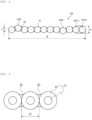
- FIG. 3 is an enlarged sectional view of a principal part of an embodiment of the optical fiber ribbon 100 according to the present invention
- FIG. 4 is an enlarged sectional view of a principal part of another embodiment of the optical fiber ribbon according to the present invention.
- the embodiment shown in FIG. 3 may be a general optical fiber ribbon 100 in which each optical fiber 10 constituting the optical fiber ribbon 100 has a diameter of 230 ⁇ m to 270 um
- the embodiment shown in FIG. 4 may be a small-diameter optical fiber ribbon 100 in which each optical fiber 10 constituting the optical fiber ribbon 100 has a diameter of 180 ⁇ m to 220 ⁇ m.
- each optical fiber 10 constituting the optical fiber ribbon 100 may include a glass core 11 and a clad layer 13 configured to wrap the glass core, the clad layer being cured using a UV curable resin.
- the optical fiber ribbon 100 shown in FIG. 3 is formed by bonding 12 general optical fibers 10 to each other, and therefore most of the adjacent optical fibers 10 must be bonded to each other in a circumscribed state, as shown in FIG. 2 or 3 , since there is a limit to the width W of the 12-core optical fiber ribbon 100 of 3.22 mm (3,220 um) based on the IEC standards or ANSI/ICEA standards related to optical fiber ribbons or fibers.
- the number of the bonding parts 20 where the optical fibers 10 are bonded to each other in a circumscribed state, among the plurality of bonding parts 20, may be greater than the number of the bonding parts 20 where the optical fibers 10 are bonded to each other in a state of being spaced apart from each other.
- the optical fiber ribbon 100 shown in FIG. 4 is formed by bonding 12 small-diameter optical fibers 10 to each other, and the sum of diameters of the optical fibers is merely a maximum of 2,640 ⁇ m, which is less than 3.22 mm (3,220 ⁇ m), which is a limit of the width of the 12-core optical fiber ribbon 100.
- bonding performance may be better when the optical fibers 10 are bonded to each other using a resin in a state of being spaced apart from each other to form the bonding parts 20, as shown in FIG. 4 , than when the optical fibers 10 are bonded to each other in a circumscribed state. That is, when the optical fiber ribbon 100 is formed by bonding the 12 small-diameter optical fibers 10 to each other, the bonding parts 20 may be formed in the state in which most of the optical fibers 10 are spaced apart from each other.
- the number of the bonding parts 20 where the optical fibers 10 are bonded to each other in a state of being spaced apart from each other, among the plurality of bonding parts 20, may be greater than the number of the bonding parts 20 where the optical fibers 10 are bonded to each other in a circumscribed state.
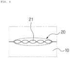
- FIGs. 5 and 6 are enlarged views of bonding parts 20 of other embodiments of the optical fiber ribbon 100 according to the present invention.
- one bonding part 20 configured to bond a pair of optical fibers 10 to each other is configured as a resin-filled form
- one bonding part 20 may include a plurality of adhesion points 21.
- a pair of optical fibers 10 is connected to each other in a circumscribed state, and one bonding part 20 configured to bond the pair of circumscribed optical fibers 10 to each other includes five adhesion points 21, whereby the amount of resin that fills one bonding part 20 may be reduced, whereby greater flexibility may be provided. Even though the amount of resin is reduced to improve flexibility, the longitudinal length b of the optical fiber ribbon 100 in the non-bonding region that is not bonded by the bonding part 20 in the width direction of the optical fiber ribbon 100 may be kept approximately the same.
- one bonding 20 may include a plurality of adhesion points 21, and optical fibers 10 may be bonded to each other in a state of being minutely spaced apart from each other.
- the optical fibers 10 may be bonded to each other in the state in which the optical fibers are minutely spaced apart from each other such that a plurality of adhesion points constitutes one bonding part, since the size or volume of the adhesion points 21 is less than that of each bonding part 20. In this case, it is possible to further improve flexibility of the bonding parts 20 along with bonding stability.
Landscapes
- Physics & Mathematics (AREA)
- General Physics & Mathematics (AREA)
- Optics & Photonics (AREA)
- Engineering & Computer Science (AREA)
- Manufacturing & Machinery (AREA)
- Mechanical Coupling Of Light Guides (AREA)
- Optical Fibers, Optical Fiber Cores, And Optical Fiber Bundles (AREA)
- Light Guides In General And Applications Therefor (AREA)
Abstract
Description
- The present invention relates to an optical fiber ribbon. More particularly, the present invention relates to an optical fiber ribbon that provides a high-capacity communication network, is capable of being rolled in a width direction so as to efficiently use a space in a conduit, minimizes separation between ribbons constituting the optical fiber ribbon or damage to optical fibers during a rolling process, and facilitates overall connection or branching at a connection end.
- In order to build a large-capacity optical communication network, an optical fiber ribbon formed by bonding optical fibers in parallel to each other may be used.
- The optical fiber ribbon, in which a plurality of optical fibers is integrally bonded to each other in parallel using a resin, is generally manufactured in a strip shape, and optical fiber ribbons are stacked to form a ribbon stack having the shape of a polygonal column.
- The optical fiber ribbon is mainly used for large-capacity optical communication networks due to the advantage of overall connection for each optical fiber ribbon at a connection end.
- In general, when a plurality of tubes (or microtubes) is pre-installed in a conduit in order to build an optical communication network and an optical cable including a strip-shaped optical fiber ribbon or an optical fiber ribbon stack in the form of polygonal columns is laid in each tube, which is generally circular in section, the utilization of a space in the tube installed in the conduit is not high. In addition, it is preferable for a circular optical cable or optical unit to have a larger number of optical fiber core wires that can be received within the same sectional area.
- In order to increase the utilization of a space in a tube installed in a conduit used to build an optical communication network or to increase the number of optical fiber core wires that can be received in an optical cable or an optical unit, a rollable optical fiber ribbon that can be deformed into a cylindrical shape by rolling an optical fiber ribbon in a width direction has been introduced.
- The rollable optical fiber ribbon must satisfy various conditions, such as that optical fibers bonded to each other in a rolled state, which constitute the optical fiber ribbon, must not be easily separated from each other such that the shape of the optical fiber ribbon is maintained, that, when the rolled state is released at a connection end, the shape of the optical fiber ribbon must be restored into the form of a general strip for overall connection, that, when it is necessary to separate individual optical fibers from each other during a connection process, the individual optical fibers must be easily separated from each other, and that damage to the optical fibers must be prevented during a separation process.
- It is an object of the present invention to provide an optical fiber ribbon that provides a high-capacity communication network, is capable of being rolled in a width direction so as to efficiently use a space in a conduit, minimizes separation between ribbons constituting the optical fiber ribbon or damage to optical fibers during a rolling process, and facilitates overall connection or branching at a connection end.
- To achieve these objects, the present invention provides an optical fiber ribbon formed by bonding a plurality of optical fibers in parallel to each other, wherein each pair of adjacent optical fibers among the plurality of optical fibers is bonded to each other through a plurality of bonding parts disposed at predetermined intervals in a longitudinal direction of the optical fiber, and in the longitudinal direction of the optical fiber, a length of each of the bonding parts is 5 mm to 15 mm, a period of the bonding parts is 10 mm to 90 mm, and a length of a non-bonding part is 5 mm to 75 mm.
- And the length of the bonding part may be preferably 13.5 mm to 15 mm, the period of the bonding parts may be preferably 50 mm to 70 mm, and the length of the non-bonding part may be preferably 33.5 mm to 55 mm.
- And a longitudinal length of the optical fiber ribbon in a non-bonding region that is not bonded by the bonding part in a width direction of the optical fiber ribbon may be 0 mm to 30 mm.
- And the longitudinal length (b) of the optical fiber ribbon in the non-bonding region may be preferably 10 mm to 20 mm.
- And the optical fiber ribbon may include N optical fibers, and a position of a bonding part configured to bond an n-th optical fiber (n being a natural number equal to or greater than 1) and an (n+1)-th optical fiber among the N optical fibers in the longitudinal direction of the optical fiber may be located in a middle between positions of bonding parts configured to bond the (n+1)-th optical fiber and an (n+2)-th optical fiber (n+2 being a natural number equal to or less than N) in the longitudinal direction.
- And an upper part and/or a lower part of the bonding part may be bonded to each other in a state in which a pair of optical fibers to be bonded is circumscribed, or a pair of optical fibers may be bonded to each other at the bonding part in a state in which the pair of optical fibers is spaced apart from each other.
- And when each optical fiber has a diameter of 230 µm to 270 µm, the number of the bonding parts where the optical fibers are bonded to each other in a circumscribed state, among the plurality of bonding parts, may be greater than the number of the bonding parts where the optical fibers are bonded to each other in a state of being spaced apart from each other.
- And when each optical fiber has a diameter of 180 µm to 220 µm, the number of the bonding parts where the optical fibers are bonded to each other in a state of being spaced apart from each other, among the plurality of bonding parts, may be greater than the number of the bonding parts where the optical fibers are bonded to each other in a circumscribed state.
- And a resin constituting each bonding part may have an elongation of 120% to 250% in a cured or sintered state.
- And a resin constituting each bonding part may have a secant modulus of 1 MPa to 200 MPa at 2.5% strain in a cured or sintered state.
- And each bonding part may be formed using a general application method of a resin, and the resin used in the general application method has a viscosity of 4,000 mPa·s to 6,000 mPa·s at 25°C.
- And the general application method may be a roller application method using a roller having a resin injection portion and formed in a shape that enables periodic resin injection.
- And each bonding part may be formed using a precision application method of a resin, and the resin used in the precision application method has a viscosity of 500 mPa·s to 1,500 mPa·s at 25°C.
- And the precision application method may be a dispenser application method using a dispenser.
- And a resin constituting each bonding part may have a tensile strength of 5 MPa to 25 MPa.
- And when a coupling rate is defined as an equation below for the period (P) of the bonding parts, which is a sum of the length (a) of each bonding part and the length (c) of the non-bonding part, the coupling rate may be 5% to 50%.
-

- And the coupling rate may be more preferably 19% to 30%.
- And a rolled optical fiber ribbon formed by rolling the optical fiber ribbon, wherein at least one optical fiber constituting the optical fiber ribbon may comprise at least one optical fiber disposed in a state of not being bonded to at least one optical fiber to be bonded.
- According to the present invention, it is possible to provide an optical fiber ribbon that provides a high-capacity communication network, is capable of being rolled in a width direction in order to reduce the outer diameter of a cable so as to efficiently use a space in a conduit, minimizes separation between ribbons constituting the optical fiber ribbon or damage to optical fibers during a rolling process, and facilitates overall connection or branching at a connection end.
-
-
FIG. 1 is a plan view of an optical fiber ribbon according to the present invention. -
FIG. 2 is a sectional view of an embodiment of the optical fiber ribbon shown inFIG. 1 . -
FIG. 3 is an enlarged sectional view of a principal part of an embodiment of the optical fiber ribbon according to the present invention. -
FIG. 4 is an enlarged sectional view of a principal part of another embodiment of the optical fiber ribbon according to the present invention. -
FIGs. 5 and6 are enlarged views of bonding parts of other embodiments of the optical fiber ribbon according to the present invention. - Hereinafter, preferred embodiments of the present invention will be described in detail with reference to the accompanying drawings. However, the present invention is not limited to the embodiments described herein, and may be embodied in various different forms. Rather, these embodiments are provided such that the present invention will be thorough and complete, and will fully convey the scope of the present invention to those skilled in the art. The same reference numbers denote the same elements throughout the specification.
-
FIG. 1 is a plan view of anoptical fiber ribbon 100 according to the present invention, andFIG. 2 is a sectional view of an embodiment of theoptical fiber ribbon 100 shown inFIG. 1 . - The present invention provides an
optical fiber ribbon 100 formed by bonding a plurality of optical fibers in parallel to each other, wherein each pair of adjacent optical fibers among the plurality ofoptical fibers 10 is bonded to each other through a plurality ofbonding parts 20 disposed at predetermined intervals in a longitudinal direction of the optical fiber, the length a of each of thebonding parts 20 in the longitudinal direction of theoptical fiber 10 is 5 mm to 15 mm, the period P of thebonding parts 20 is 10 mm to 90 mm, and the length c of anon-bonding part 20 is 5 mm to 75 mm. - In general, the
optical fiber ribbon 100 refers to an optical unit formed in the shape of a strip by sequentially bonding the plurality ofoptical fibers 10 in parallel to each other. - That is, the
optical fibers 10 disposed adjacent in parallel are bonded to each other at the interface therebetween in the longitudinal direction using a resin to form theoptical fiber ribbon 100, and furthermore a plurality ofoptical fiber ribbons 100 is stacked to form a ribbon stack, which is used to construct a large-scale optical communication network in a form that can be connected at once. In order to solve the problem that efficiently using a space in a tube or a cable of a conduit with a conventionaloptical fiber ribbon 100 or ribbon stack is difficult, however, the present invention is configured such that a bonding method is changed, whereby the optical fiber ribbon can be rolled in a width direction, unlike the conventionaloptical fiber ribbon 100. - When forming an optical fiber ribbon that is capable of being rolled in the width direction, each optical fiber constituting the optical fiber ribbon may be bonded to an optical fiber adjacent thereto, through a bonding part, or may be disposed in simple contact with an optical fiber adjacent thereto in an unbonded state, resulting in an optical fiber bundle of various shapes with minimal empty space, whereby a cable including the optical fiber ribbon may have a large number of optical fiber cores in a limited space in a sheath or a tube such that the space in the tube or the optical cable can be efficiently used when laying the cable.
- In order to secure flexibility to enable rolling of the
optical fiber ribbon 100 in the width direction, the present invention is configured such that thebonding parts 20 configured to bond adjacentoptical fibers 10 to each other are not formed over the entirety of the interface between theoptical fibers 10 but thebonding parts 20 configured to bond a pair of adjacentoptical fibers 10 to each other are discontinuously disposed along the interface between the pair ofoptical fibers 10, as shown inFIG. 1 . - That is, the bonding strength of the
bonding parts 20 configured to bond theoptical fibers 10 to each other is reduced such that theoptical fiber ribbon 100 can be rolled in the width direction. As the size of eachbonding part 20 decreases and the frequency of thebonding parts 20 is lowered, it becomes easier to roll theoptical fiber ribbon 100 in the width direction in order to minimize the volume of the optical fiber ribbon. During a rolling process, however, theoptical fibers 10 may be separated from each other, and separatedoptical fibers 10 may be damaged during an installation process of theoptical fiber ribbon 100. - Conversely, if the size and frequency of the
bonding parts 20 are increased in order to prevent separation between theoptical fibers 10, theoptical fiber ribbon 100 may not easily be rolled, or when a specificoptical fiber 10 that is not connected at once needs to be branched from a connection end or a branch end, theoptical fiber 10 may be damaged during a process of branching theoptical fibers 10, or a large amount of a resin may remain on the branchedoptical fiber 10, whereby theoptical fiber 10 may not be cleanly branched. - In the present invention, therefore, a method of optimizing the length, interval, or period of each
bonding part 20 or the width of a non-bonding region in the width direction is used in order to enable rolling in the width direction, to prevent separation between theoptical fibers 10 during the rolling process, and to prevent damage to a specificoptical fiber 10 while facilitating branching when branching theoptical fiber 10. - Specifically, the present invention is configured such that the length a of each
bonding part 20 configured to bond a pair of adjacentoptical fibers 10 to each other in the longitudinal direction of theoptical fiber 10 is 5 mm to 15 mm, the period P of thebonding parts 20 is 10 mm to 90 mm, and the length c of thenon-bonding part 20 is 5 mm to 75 mm. - That is, a pair of adjacent
optical fibers 10 is not entirely bonded to each other in the longitudinal direction,bonding parts 20 each having a length a of 5 mm to 15 mm are formed at intervals of 10 mm to 90 mm, and anon-bonding part 20 that is not bonded to the bondingpart 20 is formed so as to have a length c of 5 mm to 75 mm, whereby rolling in the width direction is possible while preventing the problem that theoptical fibers 10 are separated during the rolling process. - In the length limitations, if, among the length a of the
bonding part 20 in the longitudinal direction of theoptical fiber 10, the period P of thebonding parts 20, and the length c of thenon-bonding part 20, the length a of thebonding part 20 in the longitudinal direction of the optical fiber is less than the above range and the period P of thebonding parts 20 and the length c of thenon-bonding part 20 are greater than the above ranges accordingly, rolling is possible, but a plurality ofbonding parts 20 is damaged and theoptical fibers 10 are separated from each other. If the length a of thebonding part 20 in the longitudinal direction of the optical fiber is greater than the above range and the period P of thebonding parts 20 and the length c of thenon-bonding part 20 are less than the above ranges accordingly, rolling is not easy, and theoptical fibers 10 are damaged during the rolling process or branching of a specificoptical fiber 10 is not easy. - In the embodiment shown in
FIG. 1 , the longitudinal length b of theoptical fiber ribbon 100 in the non-bonding region that is not bonded by thebonding part 20 in the width direction of theoptical fiber ribbon 100 may be configured to be about 0 mm to 30 mm, which is advantageous in securing flexibility for rolling in the width direction. - When the optical fiber ribbon is composed of N optical fibers, as shown in
FIG. 1 , the position of abonding part 20 configured to bond an n-th optical fiber 10 (n being a natural number equal to or greater than 1) and an (n+1)-thoptical fiber 10, among the Noptical fibers 10, to each other in the longitudinal direction of theoptical fiber 10 is located in the middle between the positions of twocontinuous bonding parts 20 configured to bond the (n+1)-thoptical fiber 10 and an (n+2)-th optical fiber 10 (n+2 being a natural number equal to or less than N) to each other in the longitudinal direction, whereby it is possible to equalize the longitudinal length b of theoptical fiber ribbon 100 in the non-bonding region in the width direction of theoptical fiber ribbon 100, and therefore it is possible to secure uniform width flexibility over the entire position in the longitudinal direction. - In the embodiment shown in
FIG. 1 , theoptical fiber ribbon 100 includes 12 optical fibers, wherein, for example, the position of a plurality of spaced apart bonding parts configured to bond a fourth optical fiber (an n-th optical fiber, n=4) 10(4) and a fifth optical fiber (an (n+1)-th optical fiber) 10 to each other is located in the middle between a plurality of spaced apart bonding parts configured to bond the fifth optical fiber (the (n+1)-th optical fiber) 10(5) and a sixth optical fiber (an (n+2)-th optical fiber) 10(6) to each other, whereby the longitudinal length b of theoptical fiber ribbon 100 in the non-bonding region in the width direction of theoptical fiber ribbon 100 may be uniformly minimized in the longitudinal direction of theoptical fiber ribbon 100. - Conversely, when the position of a
bonding part 20 configured to bond an n-th optical fiber 10 (n being a natural number equal to or greater than 1) and an (n+1)-thoptical fiber 10, among the Noptical fibers 10, to each other in the longitudinal direction of theoptical fiber 10 is identical to the position of abonding part 20 configured to bond the (n+1)-thoptical fiber 10 and an (n+2)-th optical fiber 10 (n+2 being a natural number equal to or less than N) to each other in the longitudinal direction, rolling may be difficult in the bonding region where thebonding parts 20 configured to bond theoptical fibers 10 to each other are disposed in the width direction, and the length of the non-bonding region in the width direction of theoptical fiber ribbon 100 may be increased, whereby it may be difficult to roll theoptical fiber ribbon 100 into a pipe shape. - Thus, it is more preferable for
bonding parts 20 configured to bond a pair ofoptical fibers 10 to each other to be uniformly spaced apart from each other in the longitudinal direction and forbonding parts 20 configured to bond adjacent pairs ofoptical fibers 10 to each other to be staggered in the longitudinal direction. - When the length a of each
bonding part 20 configured to bond theoptical fibers 10 to each other in the longitudinal direction of theoptical fiber 10 is 5 mm to 15 mm, the period P of thebonding parts 20 is 10 mm to 90 mm, and the length c of thenon-bonding part 20 is 5 mm to 75 mm, rolling in the width direction is possible, and the problem that the optical fibers (10) are separated during the rolling process may be minimized. Preferably, the length a of eachbonding part 20 in the longitudinal direction of theoptical fiber 10 is 13.5 mm to 15 mm, the period P of thebonding parts 20 is 50 mm to 70 mm, and the length c of thenon-bonding part 20 is 33.5 mm to 55 mm. In this case, optimal rolling performance may be achieved, and damage to thebonding parts 20 or theoptical fibers 10 may be minimized. - In addition, when the length a of each
bonding part 20 in the longitudinal direction of theoptical fiber 10 is 13.5 mm to 15 mm, the period P of thebonding parts 20 is 50 mm to 70 mm, the length c of thenon-bonding part 20 is 33.5 mm to 55 mm, and the longitudinal length b of theoptical fiber ribbon 100 in the non-bonding region is 10 mm to 20 mm, it is possible to provide optimum flexibility in forming theoptical fiber ribbon 100 using the same number ofbonding parts 20 having the same length. - In order to secure flexibility and stable bonding performance of the optical fiber ribbon, the coupling rate, which is the ratio of the sum of the lengths a of the bonding parts in the longitudinal direction of the optical fiber ribbon to the sum of periods P of the bonding parts, which is the sum of the length a of the bonding part and the length c of the non-bonding part, in the longitudinal direction of the optical fiber ribbon, is 5% to 50%, preferably 19% to 30%.
- That is, when the coupling rate, which is the ratio of the bonding length of a pair of adjacent optical fibers to the total length of the optical fiber ribbon, is less than 5%, flexibility is sufficient, but some bonding parts are easily separated during the process of rolling the optical fiber ribbon or during stretching the optical fiber ribbon into a flat shape for connection at the connection end, whereby stable bonding performance is not provided, and when the coupling rate is 50% or more, sufficient flexibility to roll the optical fiber ribbon is not secured. More preferably, therefore, the appropriate compromise between flexibility and bonding performance is determined in the range of 19% to 30%.
- Even though the length a of the bonding part, and the length c of the non-bonding part, and the period P of the bonding parts are variously changed within the above ranges, therefore, it is preferable to set the coupling rate below within the range of 5% to 50%, preferably 19% to 30%.
-

- Each of the
optical fibers 10 constituting theoptical fiber ribbon 100 shown inFIGs. 1 and2 may be a small-diameter optical fiber having a diameter of 180 µm to 220 µm or an ordinary optical fiber having a diameter of 230 µm to 270 um, and when 12 optical fibers are bonded to form theoptical fiber ribbon 100, the width (W) of theoptical fiber ribbon 100 may be configured to be 3.22 mm or less, which is a limit based on IEC standards or ANSI/ICEA standards related to optical cables. - In the
optical fiber ribbon 100, ideally, the plurality ofoptical fibers 10 is bonded such that the centers of theoptical fibers 10 are disposed on the same axis based on the section shown inFIG. 2 ; however, errors may occur during the bonding process, and even when such errors occur, the deviation in height between the centers of adjacentoptical fibers 10 constituting theoptical fiber ribbon 100 is preferably minimized to provide optimal rolling performance. - In the embodiment shown in
FIG. 2 , among the 12optical fibers 10 constituting theoptical fiber ribbon 100, a second optical fiber 10(2) and a ninth optical fiber 10(9) are bonded above or below a reference height, respectively; however, the center-to-center height difference p between the second optical fiber 10(2) and the ninth optical fiber 10(9) must be 75 µm or less, which is less than the radius of eachoptical fiber 10, based on the IEC standards or ANSI/ICEA standards related to optical cables. - When an appropriate amount of resin is used, the
bonding parts 20 may be cured into an inwardly curved shape, like thebonding parts 20 shown inFIG. 2 . When the amount of the resin is not controlled and an excessive amount of the resin is injected, however, the bonding part may be cured in an outwardly curved shape, like thebonding part 20 configured to bond an 11th optical fiber 10(11) and a 12th optical fiber 10(12) to each other shown inFIG. 2 . Even though thebonding part 20 protrudes outwardly from theoptical fiber 10, as described above, the maximum thickness h of thebonding part 20 must be 360 µm or less, which is a limit based on IEC standards or ANSI/ICEA standards related to optical cables. - The
bonding part 20 of theoptical fiber ribbon 100 according to the present invention may be formed by UV curing or laser sintering various resins, such as a UV curable resin or laser sintered powder; however, it is necessary to have at least the following physical properties in a cured or sintered state such that the optical fiber ribbon can be rolled in the width direction while separation between the optical fibers is minimized during the rolling process, which has been confirmed through repeated experiments. - That is, the
bonding 20 is required to have a higher elongation than abonding part 20 using a conventionally used resin in order to allow rolling of the optical fiber ribbon, and specifically, the cured or sintered resin is required to have an elongation of at least 100%. Preferably, an elongation of 120% to 250% is advantageous for ribbon rolling characteristics. - In addition, the material is preferably selected such that secant modulus of the cured or sintered resin is about 1 MPa to 200 MPa at 2.5% strain, whereby the
bonding part 20 has lower secant modulus than abonding part 20 composed of a conventionally used resin, and therefore rolling in the width direction is possible or the rolling state can be maintained. Unless the surface of the resin is sticky after curing, the lower the secant modulus, the better the ribbon properties. However, balance between the secant modulus and the elongation must be achieved. - Accurate and rapid application of the resin must be performed to form the plurality of
optical fibers 20 spaced apart from each other in the longitudinal direction of the optical fiber, and the viscosity of the resin may have a limited range of values depending on a method used at the time of manufacture in order to achieve adequate flowability to prevent dripping prior to curing or sintering. A resin used in a roller application method using a roller, which is a common application method, has a viscosity of 4,000 mPa·s to 6,000 mPa·s at 25°C, but for a dispenser application method, which uses a dispenser for precision application, the viscosity of the resin is preferably in the range of 500 mPa·s to 1,500 mPa·s. - The roller application method is a method using a roller having a resin injection portion and formed in a shape that enables periodic resin injection.
- In addition, it is preferable to have a tensile strength of 5 MPa to 25 MPa in order to return the rolled ribbon to the original flat shape for overall connection.
-
FIG. 3 is an enlarged sectional view of a principal part of an embodiment of theoptical fiber ribbon 100 according to the present invention, andFIG. 4 is an enlarged sectional view of a principal part of another embodiment of the optical fiber ribbon according to the present invention. - Specifically, the embodiment shown in
FIG. 3 may be a generaloptical fiber ribbon 100 in which eachoptical fiber 10 constituting theoptical fiber ribbon 100 has a diameter of 230 µm to 270 um, and the embodiment shown inFIG. 4 may be a small-diameteroptical fiber ribbon 100 in which eachoptical fiber 10 constituting theoptical fiber ribbon 100 has a diameter of 180 µm to 220 µm. - Here, each
optical fiber 10 constituting theoptical fiber ribbon 100 may include aglass core 11 and aclad layer 13 configured to wrap the glass core, the clad layer being cured using a UV curable resin. - The
optical fiber ribbon 100 shown inFIG. 3 is formed by bonding 12 generaloptical fibers 10 to each other, and therefore most of the adjacentoptical fibers 10 must be bonded to each other in a circumscribed state, as shown inFIG. 2 or 3 , since there is a limit to the width W of the 12-coreoptical fiber ribbon 100 of 3.22 mm (3,220 um) based on the IEC standards or ANSI/ICEA standards related to optical fiber ribbons or fibers. - That is, since the sum of the diameters of the 12
optical fibers 10 each having a diameter of 250 µm is 3,000 µm, most of theoptical fibers 10 must be bonded to each other in a circumscribed state to form thebonding part 20 even though some of theoptical fibers 10 are bonded to each other in a state of being spaced apart from each other (seeFIG. 4 ). - For the general
optical fibers 10, therefore, the number of thebonding parts 20 where theoptical fibers 10 are bonded to each other in a circumscribed state, among the plurality ofbonding parts 20, may be greater than the number of thebonding parts 20 where theoptical fibers 10 are bonded to each other in a state of being spaced apart from each other. - On the other hand, the
optical fiber ribbon 100 shown inFIG. 4 is formed by bonding 12 small-diameteroptical fibers 10 to each other, and the sum of diameters of the optical fibers is merely a maximum of 2,640 µm, which is less than 3.22 mm (3,220 µm), which is a limit of the width of the 12-coreoptical fiber ribbon 100. - When the
optical fibers 10 are discontinuously bonded to each other to form theoptical fiber ribbon 100, bonding performance may be better when theoptical fibers 10 are bonded to each other using a resin in a state of being spaced apart from each other to form thebonding parts 20, as shown inFIG. 4 , than when theoptical fibers 10 are bonded to each other in a circumscribed state. That is, when theoptical fiber ribbon 100 is formed by bonding the 12 small-diameteroptical fibers 10 to each other, thebonding parts 20 may be formed in the state in which most of theoptical fibers 10 are spaced apart from each other. - For the small-diameter
optical fibers 10, therefore, the number of thebonding parts 20 where theoptical fibers 10 are bonded to each other in a state of being spaced apart from each other, among the plurality ofbonding parts 20, may be greater than the number of thebonding parts 20 where theoptical fibers 10 are bonded to each other in a circumscribed state. - In summary, it is possible to determine whether to bond the
optical fibers 10 to each other in a circumscribed state or whether to bond theoptical fibers 10 to each other in a state of being spaced apart from each other in consideration of the diameter of theoptical fibers 10 and the width limitations of theoptical fiber ribbon 100. -
FIGs. 5 and6 are enlarged views ofbonding parts 20 of other embodiments of theoptical fiber ribbon 100 according to the present invention. - While the foregoing embodiments are examples in which one
bonding part 20 configured to bond a pair ofoptical fibers 10 to each other is configured as a resin-filled form, onebonding part 20 may include a plurality of adhesion points 21. - That is, in the example shown in
FIG. 5 , a pair ofoptical fibers 10 is connected to each other in a circumscribed state, and onebonding part 20 configured to bond the pair of circumscribedoptical fibers 10 to each other includes fiveadhesion points 21, whereby the amount of resin that fills onebonding part 20 may be reduced, whereby greater flexibility may be provided. Even though the amount of resin is reduced to improve flexibility, the longitudinal length b of theoptical fiber ribbon 100 in the non-bonding region that is not bonded by thebonding part 20 in the width direction of theoptical fiber ribbon 100 may be kept approximately the same. - In addition, as shown in
FIG. 6 , onebonding 20 may include a plurality of adhesion points 21, andoptical fibers 10 may be bonded to each other in a state of being minutely spaced apart from each other. Even when the diameter of theoptical fiber 10 is relatively large and there is a width limit of theoptical fiber ribbon 100, as described above, theoptical fibers 10 may be bonded to each other in the state in which the optical fibers are minutely spaced apart from each other such that a plurality of adhesion points constitutes one bonding part, since the size or volume of the adhesion points 21 is less than that of eachbonding part 20. In this case, it is possible to further improve flexibility of thebonding parts 20 along with bonding stability. - Although preferred embodiments of the present invention have been described in this specification, those skilled in the art will appreciate that various changes and modifications are possible without departing from the idea and scope of the present invention recited in the appended claims. Therefore, it should be understood that such changes and modifications fall within the technical category of the present invention as long as the changes and modifications include elements described in the claims of the present invention.
Claims (18)
- An optical fiber ribbon formed by bonding a plurality of optical fibers in parallel to each other, whereineach pair of adjacent optical fibers among the plurality of optical fibers is bonded to each other through a plurality of bonding parts disposed at predetermined intervals in a longitudinal direction of the optical fiber, andin the longitudinal direction of the optical fiber, a length of each of the bonding parts is 5 mm to 15 mm, a period of the bonding parts is 10 mm to 90 mm, and a length of a non-bonding part is 5 mm to 75 mm.
- The optical fiber ribbon according to claim 1, wherein the length of the bonding part is preferably 13.5 mm to 15 mm, the period of the bonding parts is preferably 50 mm to 70 mm, and the length of the non-bonding part is preferably 33.5 mm to 55 mm.
- The optical fiber ribbon according to claim 1, wherein a longitudinal length of the optical fiber ribbon in a non-bonding region that is not bonded by the bonding part in a width direction of the optical fiber ribbon is 0 mm to 30 mm.
- The optical fiber ribbon according to claim 3, wherein the longitudinal length (b) of the optical fiber ribbon in the non-bonding region is preferably 10 mm to 20 mm.
- The optical fiber ribbon according to claim 1, whereinthe optical fiber ribbon includes N optical fibers, anda position of a bonding part configured to bond an n-th optical fiber (n being a natural number equal to or greater than 1) and an (n+1)-th optical fiber among the N optical fibers in the longitudinal direction of the optical fiber is located in a middle between positions of bonding parts configured to bond the (n+1)-th optical fiber and an (n+2)-th optical fiber (n+2 being a natural number equal to or less than N) in the longitudinal direction.
- The optical fiber ribbon according to claim 1, whereinan upper part and/or a lower part of the bonding part are bonded to each other in a state in which a pair of optical fibers to be bonded is circumscribed, ora pair of optical fibers is bonded to each other at the bonding part in a state in which the pair of optical fibers is spaced apart from each other.
- The optical fiber ribbon according to claim 6, whereinwhen each optical fiber has a diameter of 230 µm to 270 µm,the number of the bonding parts where the optical fibers are bonded to each other in a circumscribed state, among the plurality of bonding parts, is greater than the number of the bonding parts where the optical fibers are bonded to each other in a state of being spaced apart from each other.
- The optical fiber ribbon according to claim 6, whereinwhen each optical fiber has a diameter of 180 µm to 220 µm,the number of the bonding parts where the optical fibers are bonded to each other in a state of being spaced apart from each other, among the plurality of bonding parts, is greater than the number of the bonding parts where the optical fibers are bonded to each other in a circumscribed state.
- The optical fiber ribbon according to claim 1, wherein a resin constituting each bonding part has an elongation of 120% to 250% in a cured or sintered state.
- The optical fiber ribbon according to claim 1, wherein a resin constituting each bonding part has a secant modulus of 1 MPa to 200 MPa at 2.5% strain in a cured or sintered state.
- The optical fiber ribbon according to claim 1, whereineach bonding part is formed using a general application method of a resin, andthe resin used in the general application method has a viscosity of 4,000 mPa·s to 6,000 mPa·s at 25°C.
- The optical fiber ribbon according to claim 11, wherein the general application method is a roller application method using a roller having a resin injection portion and formed in a shape that enables periodic resin injection.
- The optical fiber ribbon according to claim 1, whereineach bonding part is formed using a precision application method of a resin, andthe resin used in the precision application method has a viscosity of 500 mPa·s to 1,500 mPa·s at 25°C.
- The optical fiber ribbon according to claim 13, wherein the precision application method is a dispenser application method using a dispenser.
- The optical fiber ribbon according to claim 1, wherein a resin constituting each bonding part has a tensile strength of 5 MPa to 25 MPa.
- The optical fiber ribbon according to claim 1, whereinwhen a coupling rate is defined as an equation below for the period (P) of the bonding parts, which is a sum of the length (a) of each bonding part and the length (c) of the non-bonding part,the coupling rate is 5% to 50%.- Below -

- The optical fiber ribbon according to claim 16, wherein the coupling rate is more preferably 19% to 30%.
- A rolled optical fiber ribbon formed by rolling the optical fiber ribbon according to any one of claims 1 to 17, wherein at least one optical fiber constituting the optical fiber ribbon comprises at least one optical fiber disposed in a state of not being bonded to at least one optical fiber to be bonded.
Applications Claiming Priority (1)
| Application Number | Priority Date | Filing Date | Title |
|---|---|---|---|
| PCT/KR2021/009442 WO2023003056A1 (en) | 2021-07-21 | 2021-07-21 | Optical fiber ribbon |
Publications (2)
| Publication Number | Publication Date |
|---|---|
| EP4375719A1 true EP4375719A1 (en) | 2024-05-29 |
| EP4375719A4 EP4375719A4 (en) | 2025-04-23 |
Family
ID=84980537
Family Applications (1)
| Application Number | Title | Priority Date | Filing Date |
|---|---|---|---|
| EP21951004.7A Pending EP4375719A4 (en) | 2021-07-21 | 2021-07-21 | FIBER OPTIC RIBBON |
Country Status (5)
| Country | Link |
|---|---|
| US (1) | US20240345355A1 (en) |
| EP (1) | EP4375719A4 (en) |
| CN (1) | CN117581138A (en) |
| CA (1) | CA3226013A1 (en) |
| WO (1) | WO2023003056A1 (en) |
Families Citing this family (1)
| Publication number | Priority date | Publication date | Assignee | Title |
|---|---|---|---|---|
| CN118707670A (en) * | 2024-06-03 | 2024-09-27 | 南京华信藤仓光通信有限公司 | Bonding type optical fiber ribbon and its preparation device and preparation method |
Family Cites Families (16)
| Publication number | Priority date | Publication date | Assignee | Title |
|---|---|---|---|---|
| JP5564026B2 (en) * | 2011-10-18 | 2014-07-30 | 株式会社フジクラ | Optical fiber tape core and optical fiber cable storing the optical fiber core |
| CA3178019A1 (en) * | 2012-05-02 | 2013-11-07 | Afl Telecommunications Llc | Round and small diameter optical cables with a ribbon-like optical fiber structure |
| JP6639773B2 (en) * | 2014-09-17 | 2020-02-05 | 古河電気工業株式会社 | Loose tube optical fiber unit |
| CN108369324B (en) * | 2015-12-01 | 2021-06-18 | 古河电气工业株式会社 | Fiber optic ribbon and fiber optic cable |
| US10718917B2 (en) * | 2018-08-24 | 2020-07-21 | Prysmian S.P.A. | Flexible optical fiber ribbons and methods of formation thereof |
| US20200174209A1 (en) * | 2018-12-03 | 2020-06-04 | Ofs Fitel, Llc | Compact indoor optical fiber backbone cable utilizing rollable ribbon |
| US20210116659A1 (en) * | 2019-10-21 | 2021-04-22 | Sterlite Technologies Limited | Optical fibre ribbon cable with low diameter optical fibres |
| KR20210145625A (en) * | 2020-05-25 | 2021-12-02 | 엘에스전선 주식회사 | Optical fiber ribbon |
| JP7084449B2 (en) * | 2020-07-10 | 2022-06-14 | 古河電気工業株式会社 | Optical fiber tape core wire, optical fiber cable |
| KR102854109B1 (en) * | 2020-07-21 | 2025-09-02 | 엘에스전선 주식회사 | Optical Fiber Ribbon |
| WO2022054940A1 (en) * | 2020-09-14 | 2022-03-17 | 住友電気工業株式会社 | Optical fiber ribbon and method for manufacturing optical fiber ribbon |
| WO2022059654A1 (en) * | 2020-09-16 | 2022-03-24 | 住友電気工業株式会社 | Optical fiber ribbon and sub-tape-type optical fiber ribbon |
| JP7652192B2 (en) * | 2020-10-26 | 2025-03-27 | 住友電気工業株式会社 | Fiber optic cables and cables with connectors |
| JPWO2023027117A1 (en) * | 2021-08-25 | 2023-03-02 | ||
| US20240319464A1 (en) * | 2021-12-27 | 2024-09-26 | Swcc Corporation | Optical fiber ribbon and slot-less optical cable |
| WO2023162680A1 (en) * | 2022-02-24 | 2023-08-31 | 昭和電線ケーブルシステム株式会社 | Optical fiber ribbon and slot-less optical cable |
-
2021
- 2021-07-21 CA CA3226013A patent/CA3226013A1/en active Pending
- 2021-07-21 EP EP21951004.7A patent/EP4375719A4/en active Pending
- 2021-07-21 WO PCT/KR2021/009442 patent/WO2023003056A1/en not_active Ceased
- 2021-07-21 US US18/580,045 patent/US20240345355A1/en active Pending
- 2021-07-21 CN CN202180100207.4A patent/CN117581138A/en active Pending
Also Published As
| Publication number | Publication date |
|---|---|
| CN117581138A (en) | 2024-02-20 |
| EP4375719A4 (en) | 2025-04-23 |
| CA3226013A1 (en) | 2023-01-26 |
| US20240345355A1 (en) | 2024-10-17 |
| WO2023003056A1 (en) | 2023-01-26 |
Similar Documents
| Publication | Publication Date | Title |
|---|---|---|
| AU2022200762B2 (en) | Round and small diameter optical cables with a ribbon-like optical fiber structure | |
| US7742667B2 (en) | Fiber optic cables and methods for forming the same | |
| US6519399B2 (en) | Fiber optic cable with profiled group of optical fibers | |
| CN101443684B (en) | Optical distribution cable and its structure | |
| CN102057309B (en) | Fiber optic cables and ribbons | |
| JP5121448B2 (en) | Wiring cable with composite molded intermediate branch point with preferential bending | |
| KR20210145625A (en) | Optical fiber ribbon | |
| EP3847491B1 (en) | Optical fiber fan-out assembly with ribbonized interface for mass fusion splicing, and fabrication method | |
| JP5235125B2 (en) | Optical fiber tape and optical fiber cable | |
| US20010007604A1 (en) | Fiber optic cable with profiled group of optical fibers | |
| WO2007053371A1 (en) | Fiber optic cables suitable for automated preconnectorization | |
| KR20140079824A (en) | Optical fiber tape core wire and optical fiber cable housing optical fiber tape core wire | |
| CN115524784B (en) | Self-assembled ultra-dense stacked optical fiber ribbon, preparation method thereof, optical unit and optical fiber ribbon cable | |
| CN102375191A (en) | Fiber optic cable furcation methods and assemblies | |
| KR102854109B1 (en) | Optical Fiber Ribbon | |
| CN101128764A (en) | Distributed fiber optic cable having at least one access location and method of making same | |
| CN113341520B (en) | Central beam tube type large-core-number ribbon optical cable | |
| US20240345355A1 (en) | Optical fiber ribbon | |
| CN110140072A (en) | High density, low bend loss optical fiber tape cable | |
| CN101872044B (en) | Fiber optic distribution cables and structures therefor | |
| US12436352B2 (en) | Optical fiber ribbon | |
| US20070201799A1 (en) | Fiber optic cables having a toning lobe | |
| KR20220139558A (en) | Optical ribbon and optical cable having the same | |
| DE19838351A1 (en) | Optical cable for data or information transmission | |
| EP4235245A2 (en) | Pre-terminated optical cable |
Legal Events
| Date | Code | Title | Description |
|---|---|---|---|
| STAA | Information on the status of an ep patent application or granted ep patent |
Free format text: STATUS: THE INTERNATIONAL PUBLICATION HAS BEEN MADE |
|
| PUAI | Public reference made under article 153(3) epc to a published international application that has entered the european phase |
Free format text: ORIGINAL CODE: 0009012 |
|
| STAA | Information on the status of an ep patent application or granted ep patent |
Free format text: STATUS: REQUEST FOR EXAMINATION WAS MADE |
|
| 17P | Request for examination filed |
Effective date: 20240116 |
|
| AK | Designated contracting states |
Kind code of ref document: A1 Designated state(s): AL AT BE BG CH CY CZ DE DK EE ES FI FR GB GR HR HU IE IS IT LI LT LU LV MC MK MT NL NO PL PT RO RS SE SI SK SM TR |
|
| DAV | Request for validation of the european patent (deleted) | ||
| DAX | Request for extension of the european patent (deleted) | ||
| A4 | Supplementary search report drawn up and despatched |
Effective date: 20250321 |
|
| RIC1 | Information provided on ipc code assigned before grant |
Ipc: G02B 6/44 20060101AFI20250317BHEP |