EP4375688A1 - Method and apparatus for diagnosing battery cell - Google Patents
Method and apparatus for diagnosing battery cell Download PDFInfo
- Publication number
- EP4375688A1 EP4375688A1 EP22904522.4A EP22904522A EP4375688A1 EP 4375688 A1 EP4375688 A1 EP 4375688A1 EP 22904522 A EP22904522 A EP 22904522A EP 4375688 A1 EP4375688 A1 EP 4375688A1
- Authority
- EP
- European Patent Office
- Prior art keywords
- slope
- battery cell
- reactance
- cell
- battery
- Prior art date
- Legal status (The legal status is an assumption and is not a legal conclusion. Google has not performed a legal analysis and makes no representation as to the accuracy of the status listed.)
- Granted
Links
Images







Classifications
-
- H—ELECTRICITY
- H01—ELECTRIC ELEMENTS
- H01M—PROCESSES OR MEANS, e.g. BATTERIES, FOR THE DIRECT CONVERSION OF CHEMICAL ENERGY INTO ELECTRICAL ENERGY
- H01M10/00—Secondary cells; Manufacture thereof
- H01M10/42—Methods or arrangements for servicing or maintenance of secondary cells or secondary half-cells
- H01M10/44—Methods for charging or discharging
-
- G—PHYSICS
- G01—MEASURING; TESTING
- G01R—MEASURING ELECTRIC VARIABLES; MEASURING MAGNETIC VARIABLES
- G01R31/00—Arrangements for testing electric properties; Arrangements for locating electric faults; Arrangements for electrical testing characterised by what is being tested not provided for elsewhere
- G01R31/36—Arrangements for testing, measuring or monitoring the electrical condition of accumulators or electric batteries, e.g. capacity or state of charge [SoC]
- G01R31/389—Measuring internal impedance, internal conductance or related variables
-
- G—PHYSICS
- G01—MEASURING; TESTING
- G01N—INVESTIGATING OR ANALYSING MATERIALS BY DETERMINING THEIR CHEMICAL OR PHYSICAL PROPERTIES
- G01N27/00—Investigating or analysing materials by the use of electric, electrochemical, or magnetic means
- G01N27/02—Investigating or analysing materials by the use of electric, electrochemical, or magnetic means by investigating impedance
-
- G—PHYSICS
- G01—MEASURING; TESTING
- G01N—INVESTIGATING OR ANALYSING MATERIALS BY DETERMINING THEIR CHEMICAL OR PHYSICAL PROPERTIES
- G01N27/00—Investigating or analysing materials by the use of electric, electrochemical, or magnetic means
- G01N27/02—Investigating or analysing materials by the use of electric, electrochemical, or magnetic means by investigating impedance
- G01N27/026—Dielectric impedance spectroscopy
-
- G—PHYSICS
- G01—MEASURING; TESTING
- G01R—MEASURING ELECTRIC VARIABLES; MEASURING MAGNETIC VARIABLES
- G01R31/00—Arrangements for testing electric properties; Arrangements for locating electric faults; Arrangements for electrical testing characterised by what is being tested not provided for elsewhere
- G01R31/36—Arrangements for testing, measuring or monitoring the electrical condition of accumulators or electric batteries, e.g. capacity or state of charge [SoC]
- G01R31/367—Software therefor, e.g. for battery testing using modelling or look-up tables
-
- G—PHYSICS
- G01—MEASURING; TESTING
- G01R—MEASURING ELECTRIC VARIABLES; MEASURING MAGNETIC VARIABLES
- G01R31/00—Arrangements for testing electric properties; Arrangements for locating electric faults; Arrangements for electrical testing characterised by what is being tested not provided for elsewhere
- G01R31/36—Arrangements for testing, measuring or monitoring the electrical condition of accumulators or electric batteries, e.g. capacity or state of charge [SoC]
- G01R31/392—Determining battery ageing or deterioration, e.g. state of health
-
- G—PHYSICS
- G01—MEASURING; TESTING
- G01R—MEASURING ELECTRIC VARIABLES; MEASURING MAGNETIC VARIABLES
- G01R31/00—Arrangements for testing electric properties; Arrangements for locating electric faults; Arrangements for electrical testing characterised by what is being tested not provided for elsewhere
- G01R31/36—Arrangements for testing, measuring or monitoring the electrical condition of accumulators or electric batteries, e.g. capacity or state of charge [SoC]
- G01R31/396—Acquisition or processing of data for testing or for monitoring individual cells or groups of cells within a battery
-
- H—ELECTRICITY
- H01—ELECTRIC ELEMENTS
- H01M—PROCESSES OR MEANS, e.g. BATTERIES, FOR THE DIRECT CONVERSION OF CHEMICAL ENERGY INTO ELECTRICAL ENERGY
- H01M10/00—Secondary cells; Manufacture thereof
- H01M10/42—Methods or arrangements for servicing or maintenance of secondary cells or secondary half-cells
-
- H—ELECTRICITY
- H01—ELECTRIC ELEMENTS
- H01M—PROCESSES OR MEANS, e.g. BATTERIES, FOR THE DIRECT CONVERSION OF CHEMICAL ENERGY INTO ELECTRICAL ENERGY
- H01M10/00—Secondary cells; Manufacture thereof
- H01M10/42—Methods or arrangements for servicing or maintenance of secondary cells or secondary half-cells
- H01M10/44—Methods for charging or discharging
- H01M10/446—Initial charging measures
-
- H—ELECTRICITY
- H01—ELECTRIC ELEMENTS
- H01M—PROCESSES OR MEANS, e.g. BATTERIES, FOR THE DIRECT CONVERSION OF CHEMICAL ENERGY INTO ELECTRICAL ENERGY
- H01M10/00—Secondary cells; Manufacture thereof
- H01M10/42—Methods or arrangements for servicing or maintenance of secondary cells or secondary half-cells
- H01M10/48—Accumulators combined with arrangements for measuring, testing or indicating the condition of cells, e.g. the level or density of the electrolyte
-
- Y—GENERAL TAGGING OF NEW TECHNOLOGICAL DEVELOPMENTS; GENERAL TAGGING OF CROSS-SECTIONAL TECHNOLOGIES SPANNING OVER SEVERAL SECTIONS OF THE IPC; TECHNICAL SUBJECTS COVERED BY FORMER USPC CROSS-REFERENCE ART COLLECTIONS [XRACs] AND DIGESTS
- Y02—TECHNOLOGIES OR APPLICATIONS FOR MITIGATION OR ADAPTATION AGAINST CLIMATE CHANGE
- Y02E—REDUCTION OF GREENHOUSE GAS [GHG] EMISSIONS, RELATED TO ENERGY GENERATION, TRANSMISSION OR DISTRIBUTION
- Y02E60/00—Enabling technologies; Technologies with a potential or indirect contribution to GHG emissions mitigation
- Y02E60/10—Energy storage using batteries
Definitions
- the present invention relates to a method and an apparatus for diagnosing a battery cell.
- An electric vehicle or hybrid vehicle is a vehicle that generally obtains power by driving a motor by using a battery as a power source, and research is being actively conducted in that the electric vehicle is an alternative capable of solving the pollution and energy problems of internal combustion vehicles.
- rechargeable batteries are used in various external devices other than electric vehicles.
- lithium may be precipitated on the electrode depending on the usage environment of charging and discharging. Since lithium precipitation is one of the direct causes of battery ignition problems, a diagnosis method for detecting lithium precipitation is required. In particular, since it is difficult to detect lithium precipitation after manufacturing and selling batteries, a diagnosis method for detecting lithium precipitation during a battery production process is required.
- Certain example embodiments of the present invention may provide a method and an apparatus for diagnosing a battery cell capable of detecting lithium precipitation in an activation process.
- An example embodiment of the present invention may provide a method of diagnosing a battery cell.
- the method may include: applying an activation waveform having a predetermined frequency to the battery cell in an activation process; performing an electrochemical impedance spectroscopy (EIS) measurement in a charging section of the activation process; based on the EIS measurement, calculating a slope of a reactance of the battery cell in a voltage section of a predetermined range; and diagnosing the battery cell based on the slope.
- EIS electrochemical impedance spectroscopy
- the apparatus may include a charger/discharger, an EIS meter, and a processor.
- the charger/discharger may be configured to apply an activation waveform having a predetermined frequency to the battery cell in an activation process
- the EIS meter may be configured to perform EIS measurement in a charging section of the activation process.
- the processor may be configured to calculate a slope of a reactance of the battery cell in a voltage section of a predetermined range based on the EIS measurement, and diagnose the battery cell based on the slope.
- the apparatus may further include a memory configured to store information on a reactance slope of a normal cell and a reactance slope of a defective cell for each frequency.
- the processor may obtain information on the reactance slope of the normal cell and the reactance slope of the defective cell corresponding to the predetermined frequency from the memory, diagnose the battery cell as a normal cell when the reactance slope in the voltage section of the predetermined range is included in the reactance slope of the normal cell, and diagnose the battery cell as a defective cell when the reactance slope in the voltage section of the predetermined range is included in the reactance slope of the defective cell.
- Still another example embodiment of the present invention may provide a computer program stored in a non-volatile recording medium and can be executed by a computing device.
- the computer program may cause the computing device to execute a method comprising an operation of calculating a slope of a reactance of a battery cell in a voltage section of a predetermined range based on an electrochemical impedance spectroscopy (EIS) measurement performed in a charging section of an activation process for applying an activation waveform with a predetermined frequency to the battery cell, and an operation of diagnosing the battery cell based on the slope.
- EIS electrochemical impedance spectroscopy
- the diagnosing of the battery cell may include diagnosing the battery cell as a defective cell when the slope is equal to or less than a threshold value.
- the threshold value may be -8.2.
- the threshold value may be -8.
- the predetermined frequency may be equal to or less than 25 Hz.
- the predetermined frequency may be equal to or greater than 1 Hz and equal to or less than 25 Hz.
- the voltage section may include a section between 3.5V and 3.8V.
- FIG. 20 is a flowchart illustrating an example of a diagnosis method of the battery diagnosis apparatus according to an example embodiment of the present invention.
- FIG. 1 is a diagram illustrating an example of a battery diagnosis apparatus according to an example embodiment of the present invention.
- a battery diagnosis apparatus 100 is connected to battery cells 10 and diagnoses defective cells in which lithium precipitation occurs among the battery cells 10.
- the battery diagnosis apparatus 100 may be connected to the plurality of battery cells 10 to diagnose the plurality of battery cells 10.
- the battery cell 10 may be, for example, a lithium battery, such as a lithium ion battery or a lithium ion polymer battery.
- the battery diagnosis apparatus 100 includes a charger/discharger 110, an electrochemical impedance spectroscopy (EIS) meter 120, and a processor 130.
- the processor 130 may be provided as a computing device.
- the battery cell 10 may be manufactured by injecting an electrolyte into an electrode assembly including a negative electrode, a positive electrode, and a separator. Such a battery cell 10 may function as a battery by activation through charging and discharging, and this process is referred to as an activation process.
- the charger/discharger 110 may charge or discharge the battery cell 10 by applying an activation waveform to the battery cell 10 in the activation process.
- the activation waveform may be an AC potential having a predetermined frequency.
- the charger/discharger 110 may apply an activation waveform to the positive electrode terminal of the battery cell 10 in the state where a negative electrode terminal of the battery cell 10 is connected to a ground terminal.
- the charger/discharger 110 includes a plurality of channels to which the plurality of battery cells 10 is respectively connected, and may apply an activation waveform to each of the plurality of channels to charge or discharge the plurality of battery cells 10.
- the EIS meter 120 performs EIS measurement on the battery cell 10 while the battery cell 10 is being charged or discharged. In some example embodiments, the EIS meter 120 may perform in-situ EIS measurements. The EIS meter 120 measures the response of the battery cell 10 while applying the activation waveform, and measures an imaginary component of impedance of the battery cell 10, that is, reactance based on the activation waveform and the response of the battery cell 10. In some example embodiments, the EIS meter 120 may measure an AC current response (that is, output current) of the battery cell 10 while applying the activation waveform (AC potential), and measure reactance of the battery cell 10 based on the AC potential and the output current.
- AC current response that is, output current
- AC potential activation waveform
- the EIS meter 120 may measure the reactance of the battery cell 10 by determining the phase shift and amplitude change of the output current based on the AC current response. Also, the EIS meter 120 may measure the voltage (that is, charging voltage) of the battery cell 10 in the charging section of the battery cell 10 while applying the activation waveform.
- the processor 130 calculates a slope (change) of the reactance in a voltage section of a predetermined range based on the measurement result of the EIS meter 120, and diagnoses whether the battery cell 10 is a defective cell or a normal cell based on the slope of the reactance. In some example embodiments, the processor 130 may diagnose whether the battery cell 10 is a defective cell or a normal cell based on the slope of the reactance of the battery cell 10 according to the voltage of the battery cell 10 in a voltage section of a predetermined range among the voltages of the battery cell 10 in the charging section.
- the processor 130 may diagnose the corresponding battery cell 10 as a defective cell.
- FIGS. 2 , 3 , 4 , 5 , 6 , 7 , 8 , 9 , 10 , 11 , 12 , 13 , 14 , 15 , 16 , 17 , 18 , and 19 are respectively diagrams illustrating results of analyzing voltage and reactance of a battery cell measured in a charging section of an activation process while changing a frequency of an activation waveform.
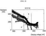
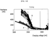
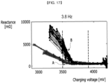
- the horizontal axis represents voltage [mV] and the vertical axis represents reactance [m ⁇ ].
- FIG. 2 illustrates a case where the frequency is 55.3 Hz
- FIG. 3 illustrates a case where the frequency is 43.9 Hz
- FIG. 4 illustrates a case where the frequency is 34.3 Hz
- FIG. 5 illustrates a case where the frequency is 26.7 Hz
- FIG. 6 illustrates a case where the frequency is 24.8 Hz
- FIG. 7 illustrates a case where the frequency is 22.9 Hz
- FIG. 8 illustrates a case where the frequency is 21.0 Hz
- FIG. 9 illustrates a case where the frequency is 19.1 Hz
- FIG. 10 illustrates a case where the frequency is 17.2 Hz
- FIG. 11 illustrates a case where the frequency is 15.3 Hz
- FIG. 12 illustrates a case where the frequency is 13.4 Hz
- FIG. 13 illustrates a case where the frequency is 11.4 Hz
- FIG. 14 illustrates a case where the frequency is 9.5 Hz
- FIG. 15 illustrates a case where the frequency is 7.6 Hz
- FIG. 16 illustrates a case where the frequency is 5.7 Hz
- FIG. 17 illustrates a case where the frequency is 3.8 Hz
- FIG. 18 illustrates a case where the frequency is 1.9 Hz
- FIG. 19 illustrates a case where the frequency is 1.0 Hz.
- a first group A is a group of reactance graphs for each of a plurality of normal cells
- a second group B is a group of reactance graphs for each of a plurality of defective cells.
- reactance graphs for each of a plurality of normal cells and a plurality of defective cells overlap each other in some sections. That is, graphs may be difficult to be distinguished from each other in some sections.
- the first group A may be distinguished by light gray and the second group B may be distinguished by black. Meanwhile, although the boundary between the first group A and the second group B may be unclear in some voltage sections, data required in the present invention are disclosed in Table 1 below.
- a reactance slope for a predetermined battery cell 10 may be calculated based on a difference value between a first reactance value corresponding to 3.5V and a second reactance value corresponding to 3.8V. That is, even though the reactance value exhibits the form of the graph increasing or decreasing more than the first reactance value or the second reactance value in the charging voltage section between 3.5V and 3.8V, the reactance slope may be calculated based on the first reactance value and the second reactance value.
- the present invention is not limited thereto, and according to various example embodiments, a reactance slope may be calculated in the charging voltage section between 3.5V and 3.8V.
- 'SL_1' may be a reactance slope for a normal cell
- SL_2' may be a reactance slope for a defective cell
- the reactance slope SL_1 or SL_2 may be graphs corresponding to a maximum value among a plurality of reactance slopes corresponding to the first group A or the second group B.
- the present invention is not limited thereto, and the reactance slopes SL_1 or SL_2 may indicate a minimum value or an average value among a plurality of reactance slopes corresponding to the first group A or the second group B.
- the reactance rapidly decreases as the charging voltage increases in the voltage section of a predetermined range.
- the reactance slope of the defective cell according to the increase in the charging voltage is distinguished from the reactance slope of the normal cell.
- the magnitude (absolute value) of the reactance slope in the section where the charging voltage is 3.5V or more and 3.8V or less is greater than the magnitude of the reactance slope in other charging voltage sections.
- FIGS. 6 to 19 it can be seen that when an activation waveform having a frequency of 1 Hz or more and 25 Hz or less is used, the magnitude of the reactance slope of the defective cell is significantly larger than that of the normal cell to a distinguishable extent.
- FIGS. 2 to 5 and 19 it can be seen that when an activation waveform having a frequency higher than 25 Hz is used, it is difficult to compare the magnitude of the reactance slope of a defective cell with the magnitude of the reactance slope of a normal cell.
- the reactance slope in the charging voltage section between 3.5V and 3.8V illustrated in FIGS. 2 to 19 is digitized, the result is given as represented in Table 1.
- Table 1 the information on the reactance slope of each normal cell and the reactance slope of a defective cell for each frequency may be stored in a memory (not illustrated) of the battery diagnosis apparatus (reference numeral 100 in FIG. 1 ).
- Table 1 shows the maximum value, minimum value, and average value of the reactance slope. Specifically, Table 1 shows the maximum value, minimum value, and average value among the plurality of reactance slopes belonging to the first group A for each frequency of the activation waveform. Further, Table 1 shows the maximum value, minimum value, and average value among the plurality of reactance slopes belonging to the second group B for each frequency of the activation waveform.
- the first group A is a group of reactance graphs for each of a plurality of normal cells
- the second group B is a group of reactance graphs for each of a plurality of defective cells.
- the frequency of the activation waveform when the frequency of the activation waveform is greater than 25 Hz, since the section of the reactance slope of the defective cell partially overlaps the section of the reactance slope of the normal cell, it may be difficult to distinguish the reactance slope of the defective cell from the normal cell.
- the frequency of the activation waveform is 55.3 Hz
- the reactance slope of the defective cell has a value between -6.03 and -5.00
- the reactance slope of the normal cell has a value between -6.85 and -3.26. Accordingly, when a reactance slope of a certain battery cell is measured as - 6.00, it cannot be distinguished whether the corresponding battery cell is a normal cell or a defective cell.
- the reactance slope of the defective cell has a value between -9.40 and -7.51
- the reactance slope of the normal cell has a value between -7.54 and -2.40. Accordingly, when a reactance slope of a certain battery cell is measured as -7.52, it cannot be distinguished whether the corresponding battery cell is a normal cell or a defective cell.
- the reactance slope of a defective cell and the reactance slope of a normal cell may be distinguished.
- the frequency of the activation waveform is 24.8 Hz
- the reactance slope of the defective cell has a value between -10.86 and -8.20
- the reactance slope of a normal cell has a value between -6.91 and -2.45
- the corresponding battery cell may be determined to be a defective cell.
- the frequency of the activation waveform is 1.0 Hz, 1.9 Hz, 3.6 Hz, 5.7 Hz, 7.6 Hz, 9.5 Hz, 11.4 Hz, 13.4 Hz, 15.3 Hz, 17.2 Hz, 19.1 Hz, 21 Hz, or 22.9 Hz
- a normal cell and a defective cell may be distinguished by the reactance slope.
- a discharge cell having a reactance slope of - 8.2, that is, a threshold value, or less may be determined as a defective cell.
- the threshold value may be set to -8 that is greater than -8.2 in consideration of measurement error.
- FIG. 20 is a flowchart illustrating an example of a diagnosis method of the battery diagnosis apparatus according to an example embodiment of the present invention.
- the battery diagnosis apparatus performs an activation process by applying an activation waveform having a predetermined frequency to a battery cell (S210).
- the predetermined frequency may be less than 25 Hz. In some example embodiments, the predetermined frequency may be equal to or greater than 1 Hz and equal to or less than 25 Hz.
- the battery diagnosis apparatus measures reactance and a charging voltage of the battery cell by performing EIS measurement on the battery cell in the charging section of the activation process (S220).
- the battery diagnosis apparatus calculates a reactance slope of the battery cell according to the voltage of the battery cell in a charging voltage section of a predetermined range (S230).
- the charging voltage section of the predetermined range may be equal to or greater than -3.5V and equal to or less than -3.8V.
- the battery diagnosis apparatus compares the reactance slope with a threshold value (S240), and diagnoses the corresponding battery cell as a defective cell when the reactance slope is equal to or less than the threshold value (S250).
- the battery diagnosis apparatus may diagnose a corresponding battery cell as a defective cell in which lithium precipitation occurs.
- the battery diagnosis apparatus diagnoses the corresponding battery cell as a normal cell (S260).
- the threshold value may be -8.
- the threshold value may be -8.2.
- the battery diagnosis apparatus may obtain information on the reactance slopes of normal cells and the reactance slopes of defective cells corresponding to a predetermined frequency from a memory, and compare the calculated reactance slope may with the reactance slope obtained from the memory (S240).
- the battery diagnosis apparatus may diagnose the battery cell as a defective cell when the calculated reactance slope is included in the reactance slope of the defective cell (S250).
- the battery diagnosis apparatus may diagnose the battery cell as a normal cell when the calculated reactance slope is included in the reactance slope of the normal cell (S260).
- a computing device may perform operations on a computer program for executing the diagnostic method described above.
- the computer program for executing the diagnostic method may be loaded into memory.
- the computer program may include instructions that cause the computing device to perform the diagnosis method when loaded into memory.
- the computer program may cause the computing device to execute an operation of calculating a reactance slope of the battery cell in a voltage section of a predetermined range and an operation of diagnosing the battery cell based on the slope based on the EIS measurement performed in the charging section of the activation process for applying an activation waveform having a predetermined frequency to the battery cell.
Landscapes
- Physics & Mathematics (AREA)
- General Physics & Mathematics (AREA)
- Chemical & Material Sciences (AREA)
- Chemical Kinetics & Catalysis (AREA)
- Electrochemistry (AREA)
- Engineering & Computer Science (AREA)
- Manufacturing & Machinery (AREA)
- General Chemical & Material Sciences (AREA)
- Biochemistry (AREA)
- Health & Medical Sciences (AREA)
- Life Sciences & Earth Sciences (AREA)
- Analytical Chemistry (AREA)
- General Health & Medical Sciences (AREA)
- Immunology (AREA)
- Pathology (AREA)
- Spectroscopy & Molecular Physics (AREA)
- Secondary Cells (AREA)
- Tests Of Electric Status Of Batteries (AREA)
- Charge And Discharge Circuits For Batteries Or The Like (AREA)
Abstract
Description
- This application claims priority to and the benefit of
Korean Patent Application No. 10-2021-0174607 filed in the Korean Intellectual Property Office on December 8, 2021 - The present invention relates to a method and an apparatus for diagnosing a battery cell.
- An electric vehicle or hybrid vehicle is a vehicle that generally obtains power by driving a motor by using a battery as a power source, and research is being actively conducted in that the electric vehicle is an alternative capable of solving the pollution and energy problems of internal combustion vehicles. In addition, rechargeable batteries are used in various external devices other than electric vehicles.
- Among batteries, in the case of a lithium battery which uses lithium ions in a redox reaction, lithium may be precipitated on the electrode depending on the usage environment of charging and discharging. Since lithium precipitation is one of the direct causes of battery ignition problems, a diagnosis method for detecting lithium precipitation is required. In particular, since it is difficult to detect lithium precipitation after manufacturing and selling batteries, a diagnosis method for detecting lithium precipitation during a battery production process is required.
- Certain example embodiments of the present invention may provide a method and an apparatus for diagnosing a battery cell capable of detecting lithium precipitation in an activation process.
- An example embodiment of the present invention may provide a method of diagnosing a battery cell. The method may include: applying an activation waveform having a predetermined frequency to the battery cell in an activation process; performing an electrochemical impedance spectroscopy (EIS) measurement in a charging section of the activation process; based on the EIS measurement, calculating a slope of a reactance of the battery cell in a voltage section of a predetermined range; and diagnosing the battery cell based on the slope.
- Another example embodiment of the present invention may provide an apparatus for diagnosing a battery cell. The apparatus may include a charger/discharger, an EIS meter, and a processor. The charger/discharger may be configured to apply an activation waveform having a predetermined frequency to the battery cell in an activation process, and the EIS meter may be configured to perform EIS measurement in a charging section of the activation process. The processor may be configured to calculate a slope of a reactance of the battery cell in a voltage section of a predetermined range based on the EIS measurement, and diagnose the battery cell based on the slope.
- In some example embodiments, the apparatus may further include a memory configured to store information on a reactance slope of a normal cell and a reactance slope of a defective cell for each frequency. The processor may obtain information on the reactance slope of the normal cell and the reactance slope of the defective cell corresponding to the predetermined frequency from the memory, diagnose the battery cell as a normal cell when the reactance slope in the voltage section of the predetermined range is included in the reactance slope of the normal cell, and diagnose the battery cell as a defective cell when the reactance slope in the voltage section of the predetermined range is included in the reactance slope of the defective cell.
- Still another example embodiment of the present invention may provide a computer program stored in a non-volatile recording medium and can be executed by a computing device. When, executed by the computing device, the computer program may cause the computing device to execute a method comprising an operation of calculating a slope of a reactance of a battery cell in a voltage section of a predetermined range based on an electrochemical impedance spectroscopy (EIS) measurement performed in a charging section of an activation process for applying an activation waveform with a predetermined frequency to the battery cell, and an operation of diagnosing the battery cell based on the slope.
- In example embodiments, the diagnosing of the battery cell may include diagnosing the battery cell as a defective cell when the slope is equal to or less than a threshold value.
- In example embodiments, the threshold value may be -8.2.
- In example embodiments, the threshold value may be -8.
- In example embodiments, the predetermined frequency may be equal to or less than 25 Hz.
- In example embodiments, the predetermined frequency may be equal to or greater than 1 Hz and equal to or less than 25 Hz.
- In example embodiments, the voltage section may include a section between 3.5V and 3.8V.
- According to the example embodiment, it is possible to diagnose a defective cell in which lithium precipitation has occurred based on a reactance slope.
-
-
FIG. 1 is a diagram illustrating an example of a battery diagnosis apparatus according to an example embodiment of the present invention. -
FIGS. 2 ,3 ,4 ,5 ,6 ,7 ,8 ,9 ,10 ,11 ,12 ,13 ,14 ,15 ,16 ,17 ,18 , and19 are respectively diagrams illustrating results of analyzing voltage and reactance of a battery cell measured in a charging section of an activation process while changing a frequency of an activation waveform. -
FIG. 20 is a flowchart illustrating an example of a diagnosis method of the battery diagnosis apparatus according to an example embodiment of the present invention. - In the following detailed description, only certain example embodiments of the present invention have been illustrated and described, simply by way of illustration. As those skilled in the art would realize, the described example embodiments may be modified in various different ways, all without departing from the spirit or scope of the present invention. Accordingly, the drawings and description are to be regarded as illustrative in nature and not restrictive. Like reference numerals designate like elements throughout the specification.
- It should be understood that when one constituent element is referred to as being "coupled to" or "connected to" another constituent element, one constituent element can be directly coupled to or connected to the other constituent element, but intervening elements may also be present. By contrast, when one constituent element is referred to as being "directly coupled to" or "directly connected to" another constituent element, it should be understood that there are no intervening elements.
- Expressions written in the singular in the following description may be interpreted in the singular or plural unless explicit expressions, such as "one" or "single", are used.
- In the flowchart described with reference to the drawing, the order of operations may be changed, several operations may be merged, some operations may be divided, and specific operations may not be performed.
-
FIG. 1 is a diagram illustrating an example of a battery diagnosis apparatus according to an example embodiment of the present invention. - A
battery diagnosis apparatus 100 is connected tobattery cells 10 and diagnoses defective cells in which lithium precipitation occurs among thebattery cells 10. In some example embodiments, thebattery diagnosis apparatus 100 may be connected to the plurality ofbattery cells 10 to diagnose the plurality ofbattery cells 10. In some example embodiments, thebattery cell 10 may be, for example, a lithium battery, such as a lithium ion battery or a lithium ion polymer battery. - The
battery diagnosis apparatus 100 includes a charger/discharger 110, an electrochemical impedance spectroscopy (EIS)meter 120, and aprocessor 130. In some example embodiments, theprocessor 130 may be provided as a computing device. - In some example embodiments, the
battery cell 10 may be manufactured by injecting an electrolyte into an electrode assembly including a negative electrode, a positive electrode, and a separator. Such abattery cell 10 may function as a battery by activation through charging and discharging, and this process is referred to as an activation process. The charger/discharger 110 may charge or discharge thebattery cell 10 by applying an activation waveform to thebattery cell 10 in the activation process. The activation waveform may be an AC potential having a predetermined frequency. In some example embodiments, the charger/discharger 110 may apply an activation waveform to the positive electrode terminal of thebattery cell 10 in the state where a negative electrode terminal of thebattery cell 10 is connected to a ground terminal. In some example embodiments, the charger/discharger 110 includes a plurality of channels to which the plurality ofbattery cells 10 is respectively connected, and may apply an activation waveform to each of the plurality of channels to charge or discharge the plurality ofbattery cells 10. - The
EIS meter 120 performs EIS measurement on thebattery cell 10 while thebattery cell 10 is being charged or discharged. In some example embodiments, theEIS meter 120 may perform in-situ EIS measurements. TheEIS meter 120 measures the response of thebattery cell 10 while applying the activation waveform, and measures an imaginary component of impedance of thebattery cell 10, that is, reactance based on the activation waveform and the response of thebattery cell 10. In some example embodiments, theEIS meter 120 may measure an AC current response (that is, output current) of thebattery cell 10 while applying the activation waveform (AC potential), and measure reactance of thebattery cell 10 based on the AC potential and the output current. In some example embodiments, theEIS meter 120 may measure the reactance of thebattery cell 10 by determining the phase shift and amplitude change of the output current based on the AC current response. Also, theEIS meter 120 may measure the voltage (that is, charging voltage) of thebattery cell 10 in the charging section of thebattery cell 10 while applying the activation waveform. - The
processor 130 calculates a slope (change) of the reactance in a voltage section of a predetermined range based on the measurement result of theEIS meter 120, and diagnoses whether thebattery cell 10 is a defective cell or a normal cell based on the slope of the reactance. In some example embodiments, theprocessor 130 may diagnose whether thebattery cell 10 is a defective cell or a normal cell based on the slope of the reactance of thebattery cell 10 according to the voltage of thebattery cell 10 in a voltage section of a predetermined range among the voltages of thebattery cell 10 in the charging section. In some example embodiments, when the reactance slope of thebattery cell 10 according to the increase in voltage of thebattery cell 10 is equal to or less than a threshold value in the voltage section of the predetermined range, theprocessor 130 may diagnose thecorresponding battery cell 10 as a defective cell. - Next, a predetermined frequency and a voltage section of a predetermined range used in the battery diagnosis apparatus according to the example embodiment of the present invention will be described with reference to
FIGS. 2 to 19 . -
FIGS. 2 ,3 ,4 ,5 ,6 ,7 ,8 ,9 ,10 ,11 ,12 ,13 ,14 ,15 ,16 ,17 ,18 , and19 are respectively diagrams illustrating results of analyzing voltage and reactance of a battery cell measured in a charging section of an activation process while changing a frequency of an activation waveform. InFIGS. 2 to 19 , the horizontal axis represents voltage [mV] and the vertical axis represents reactance [mΩ]. -
FIG. 2 illustrates a case where the frequency is 55.3 Hz,FIG. 3 illustrates a case where the frequency is 43.9 Hz,FIG. 4 illustrates a case where the frequency is 34.3 Hz,FIG. 5 illustrates a case where the frequency is 26.7 Hz,FIG. 6 illustrates a case where the frequency is 24.8 Hz,FIG. 7 illustrates a case where the frequency is 22.9 Hz,FIG. 8 illustrates a case where the frequency is 21.0 Hz,FIG. 9 illustrates a case where the frequency is 19.1 Hz,FIG. 10 illustrates a case where the frequency is 17.2 Hz,FIG. 11 illustrates a case where the frequency is 15.3 Hz,FIG. 12 illustrates a case where the frequency is 13.4 Hz,FIG. 13 illustrates a case where the frequency is 11.4 Hz,FIG. 14 illustrates a case where the frequency is 9.5 Hz,FIG. 15 illustrates a case where the frequency is 7.6 Hz,FIG. 16 illustrates a case where the frequency is 5.7 Hz,FIG. 17 illustrates a case where the frequency is 3.8 Hz,FIG. 18 illustrates a case where the frequency is 1.9 Hz, andFIG. 19 illustrates a case where the frequency is 1.0 Hz. - In each of
FIGS. 2 to 19 , a first group A is a group of reactance graphs for each of a plurality of normal cells, and a second group B is a group of reactance graphs for each of a plurality of defective cells. In each ofFIGS. 2 to 19 , reactance graphs for each of a plurality of normal cells and a plurality of defective cells overlap each other in some sections. That is, graphs may be difficult to be distinguished from each other in some sections. However, the first group A may be distinguished by light gray and the second group B may be distinguished by black. Meanwhile, although the boundary between the first group A and the second group B may be unclear in some voltage sections, data required in the present invention are disclosed in Table 1 below. - According to the example embodiment, in the charging voltage section between 3.5V and 3.8V illustrated in
FIGS. 2 to 19 , a reactance slope for apredetermined battery cell 10 may be calculated based on a difference value between a first reactance value corresponding to 3.5V and a second reactance value corresponding to 3.8V. That is, even though the reactance value exhibits the form of the graph increasing or decreasing more than the first reactance value or the second reactance value in the charging voltage section between 3.5V and 3.8V, the reactance slope may be calculated based on the first reactance value and the second reactance value. However, the present invention is not limited thereto, and according to various example embodiments, a reactance slope may be calculated in the charging voltage section between 3.5V and 3.8V. - Referring to
FIG. 2 , 'SL_1' may be a reactance slope for a normal cell, and SL_2' may be a reactance slope for a defective cell. Also, the reactance slope SL_1 or SL_2 may be graphs corresponding to a maximum value among a plurality of reactance slopes corresponding to the first group A or the second group B. However, the present invention is not limited thereto, and the reactance slopes SL_1 or SL_2 may indicate a minimum value or an average value among a plurality of reactance slopes corresponding to the first group A or the second group B. - Referring to
FIGS. 2 to 19 , in the case of a defective cell, it can be seen that the reactance rapidly decreases as the charging voltage increases in the voltage section of a predetermined range. In particular, it can be seen that when an activation waveform having a predetermined frequency is used, the reactance slope of the defective cell according to the increase in the charging voltage is distinguished from the reactance slope of the normal cell. - As illustrated in
FIGS. 2 to 19 , it can be seen that the magnitude (absolute value) of the reactance slope in the section where the charging voltage is 3.5V or more and 3.8V or less is greater than the magnitude of the reactance slope in other charging voltage sections. In addition, as illustrated inFIGS. 6 to 19 , it can be seen that when an activation waveform having a frequency of 1 Hz or more and 25 Hz or less is used, the magnitude of the reactance slope of the defective cell is significantly larger than that of the normal cell to a distinguishable extent. - On the other hand, as illustrated in
FIGS. 2 to 5 and19 , it can be seen that when an activation waveform having a frequency higher than 25 Hz is used, it is difficult to compare the magnitude of the reactance slope of a defective cell with the magnitude of the reactance slope of a normal cell. - Specifically, when the reactance slope in the charging voltage section between 3.5V and 3.8V illustrated in
FIGS. 2 to 19 is digitized, the result is given as represented in Table 1. As shown in Table 1, the information on the reactance slope of each normal cell and the reactance slope of a defective cell for each frequency may be stored in a memory (not illustrated) of the battery diagnosis apparatus (reference numeral 100 inFIG. 1 ). - Since the reactance slope of the battery cell may change depending on the state of the battery cell, Table 1 shows the maximum value, minimum value, and average value of the reactance slope. Specifically, Table 1 shows the maximum value, minimum value, and average value among the plurality of reactance slopes belonging to the first group A for each frequency of the activation waveform. Further, Table 1 shows the maximum value, minimum value, and average value among the plurality of reactance slopes belonging to the second group B for each frequency of the activation waveform. In this case, the first group A is a group of reactance graphs for each of a plurality of normal cells, and the second group B is a group of reactance graphs for each of a plurality of defective cells.
- Referring to Table 1, when the frequency of the activation waveform is greater than 25 Hz, since the section of the reactance slope of the defective cell partially overlaps the section of the reactance slope of the normal cell, it may be difficult to distinguish the reactance slope of the defective cell from the normal cell. For example, when the frequency of the activation waveform is 55.3 Hz, the reactance slope of the defective cell has a value between -6.03 and -5.00, and the reactance slope of the normal cell has a value between -6.85 and -3.26. Accordingly, when a reactance slope of a certain battery cell is measured as - 6.00, it cannot be distinguished whether the corresponding battery cell is a normal cell or a defective cell. Similarly, when the frequency of the activation waveform is 26.7 Hz, the reactance slope of the defective cell has a value between -9.40 and -7.51, and the reactance slope of the normal cell has a value between -7.54 and -2.40. Accordingly, when a reactance slope of a certain battery cell is measured as -7.52, it cannot be distinguished whether the corresponding battery cell is a normal cell or a defective cell.
- However, when the frequency of the activation waveform is equal to or less than 25 Hz, since the section of the reactance slope of the defective cell and the section of the reactance slope of the normal cell do not overlap, the reactance slope of a defective cell and the reactance slope of a normal cell may be distinguished. For example, when the frequency of the activation waveform is 24.8 Hz, the reactance slope of the defective cell has a value between -10.86 and -8.20, and the reactance slope of a normal cell has a value between -6.91 and -2.45, so when a reactance slope of a certain battery cell is measured as a value of -8.20 or less, the corresponding battery cell may be determined to be a defective cell. Similarly, if the frequency of the activation waveform is 1.0 Hz, 1.9 Hz, 3.6 Hz, 5.7 Hz, 7.6 Hz, 9.5 Hz, 11.4 Hz, 13.4 Hz, 15.3 Hz, 17.2 Hz, 19.1 Hz, 21 Hz, or 22.9 Hz, since the section of the reactance slope of the defective cell and the section of the reactance slope of the normal cell do not overlap, a normal cell and a defective cell may be distinguished by the reactance slope.
(Table 1) frequency[H Z] Defective cell (second group, B) Normal cell (first group, A) Minimum Maximum average Minimum Maximum average 55.3 -6.03 -5.00 -5.51 -6.85 -3.26 -4.57 43.9 -7.02 -5.71 -6.38 -6.81 -2.27 -4.60 34.3 -8.36 -6.55 -7.32 -6.98 -1.72 -4.55 26.7 -9.40 -7.51 -8.48 -7.54 -2.40 -4.42 24.8 -10.86 -8.20 -9.69 -6.91 -2.45 -4.38 22.9 -12.47 -8.92 -10.98 -6.81 -1.79 -4.33 21.0 -14.76 -9.40 -12.19 -6.39 -1.37 -4.15 19.1 -16.37 -9.37 -13.14 -6.56 -0.39 -4.10 17.2 -16.73 -8.76 -13.40 -6.42 -0.67 -3.92 15.3 -16.80 -8.66 -13.56 -5.84 0.16 -3.75 13.4 -19.19 -8.58 -13.90 -6.27 -0.78 -3.54 11.4 -19.87 -7.83 -14.44 -5.89 -1.24 -3.30 9.5 -21.34 -7.52 -14.75 -5.43 0.28 -3.02 7.6 -22.05 -6.61 -14.97 -4.78 0.16 -2.70 5.7 -22.63 -5.92 -14.53 -3.87 -0.13 -2.23 3.6 -21.63 -4.92 -13.69 -3.27 0.40 -1.58 1.9 -19.53 -3.46 -11.89 -1.74 0.71 -0.97 1.0 -13.49 -2.03 -8.24 -1.59 1.04 -0.30 - As described above, when the frequency of the activation waveform is 25 Hz or less, normal cells and defective cells may be distinguished by the reactance slope in the charging voltage section between 3.5V and 3.8V. In particular, as shown in Table 1, when the frequency of the activation waveform is 25 Hz or less, since the smallest value among the maximum values of the reactance slope in the charging voltage section between 3.5V and 3.8V is -8.2, in some example embodiments, a discharge cell having a reactance slope of - 8.2, that is, a threshold value, or less may be determined as a defective cell. By setting the smallest value among the maximum values of the reactance slope as the threshold value, it is possible to prevent a normal cell from being determined as a defective cell.
- In some example embodiments, since the minimum value of the reactance slope of a normal cell at 24.8 Hz is -6.91, the threshold value may be set to -8 that is greater than -8.2 in consideration of measurement error.
-
FIG. 20 is a flowchart illustrating an example of a diagnosis method of the battery diagnosis apparatus according to an example embodiment of the present invention. - Referring to
FIG. 20 , the battery diagnosis apparatus performs an activation process by applying an activation waveform having a predetermined frequency to a battery cell (S210). In some example embodiments, the predetermined frequency may be less than 25 Hz. In some example embodiments, the predetermined frequency may be equal to or greater than 1 Hz and equal to or less than 25 Hz. The battery diagnosis apparatus measures reactance and a charging voltage of the battery cell by performing EIS measurement on the battery cell in the charging section of the activation process (S220). - The battery diagnosis apparatus calculates a reactance slope of the battery cell according to the voltage of the battery cell in a charging voltage section of a predetermined range (S230). In some example embodiments, the charging voltage section of the predetermined range may be equal to or greater than -3.5V and equal to or less than -3.8V. The battery diagnosis apparatus compares the reactance slope with a threshold value (S240), and diagnoses the corresponding battery cell as a defective cell when the reactance slope is equal to or less than the threshold value (S250). In some example embodiments, the battery diagnosis apparatus may diagnose a corresponding battery cell as a defective cell in which lithium precipitation occurs. When the reactance slope is greater than the threshold value, the battery diagnosis apparatus diagnoses the corresponding battery cell as a normal cell (S260). In some example embodiments, the threshold value may be -8. In some example embodiments, the threshold value may be -8.2.
- In some example embodiments, the battery diagnosis apparatus may obtain information on the reactance slopes of normal cells and the reactance slopes of defective cells corresponding to a predetermined frequency from a memory, and compare the calculated reactance slope may with the reactance slope obtained from the memory (S240). The battery diagnosis apparatus may diagnose the battery cell as a defective cell when the calculated reactance slope is included in the reactance slope of the defective cell (S250). The battery diagnosis apparatus may diagnose the battery cell as a normal cell when the calculated reactance slope is included in the reactance slope of the normal cell (S260).
- According to the example embodiment described above, it is possible to diagnose a defective cell in which lithium precipitation has occurred based on a reactance slope.
- In some example embodiments, a computing device (or processor) may perform operations on a computer program for executing the diagnostic method described above. The computer program for executing the diagnostic method may be loaded into memory. The computer program may include instructions that cause the computing device to perform the diagnosis method when loaded into memory. In some example embodiments, the computer program may cause the computing device to execute an operation of calculating a reactance slope of the battery cell in a voltage section of a predetermined range and an operation of diagnosing the battery cell based on the slope based on the EIS measurement performed in the charging section of the activation process for applying an activation waveform having a predetermined frequency to the battery cell.
- Although an example embodiment of the present invention has been described in detail, the scope of the present invention is not limited by the example embodiment. Various changes and modifications using the basic concept of the present invention defined in the accompanying claims by those skilled in the art shall be construed to belong to the scope of the present invention.
Claims (16)
- A method of diagnosing a battery cell, the method comprising:applying an activation waveform having a predetermined frequency to the battery cell in an activation process;performing an electrochemical impedance spectroscopy (EIS) measurement in a charging section of the activation process;based on the EIS measurement, calculating a slope of a reactance of the battery cell in a voltage section of a predetermined range; anddiagnosing the battery cell based on the slope.
- The method of claim 1, wherein the diagnosing of the battery cell includes diagnosing the battery cell as a defective cell when the slope is equal to or less than a threshold value.
- The method of claim 1, wherein the threshold value is -8.2.
- The method of claim 1, wherein the threshold value is -8.
- The method of claim 1, wherein the predetermined frequency is equal to or less than 25 Hz.
- The method of claim 5, wherein the predetermined frequency is equal to or greater than 1 Hz.
- The method of claim 1, wherein the voltage section includes a section between 3.5V and 3.8V.
- An apparatus for diagnosing a battery cell, the apparatus comprising:a charger/discharger configured to apply an activation waveform having a predetermined frequency to the battery cell in an activation process;an electrochemical impedance spectroscopy (EIS) meter configured to perform an EIS measurement in a charging section of the activation process;
anda processor configured to calculate a slope of a reactance of the battery cell in a voltage section of a predetermined range based on the EIS measurement, and diagnose the battery cell based on the slope. - The apparatus of claim 8, wherein the processor diagnoses the battery cell as a defective cell when the slope is equal to or less than a threshold value.
- The apparatus of claim 8, wherein the threshold value is -8.2.
- The apparatus of claim 8, wherein the threshold value is -8.
- The apparatus of claim 8, wherein the predetermined frequency is equal to or less than 25 Hz.
- The apparatus of claim 12, wherein the predetermined frequency is equal to or greater than 1 Hz.
- The apparatus of claim 8, wherein the voltage section includes a section between 3.5V and 3.8V.
- The apparatus of claim 8, further comprising:a memory configured to store information on a reactance slope of a normal cell and a reactance slope of a defective cell for each frequency,wherein the processor:obtains information on the reactance slope of the normal cell and the reactance slope of the defective cell corresponding to the predetermined frequency from the memory,diagnoses the battery cell as a normal cell when the reactance slope in the voltage section of the predetermined range is included in the reactance slope of the normal cell, anddiagnoses the battery cell as a defective cell when the reactance slope in the voltage section of the predetermined range is included in the reactance slope of the defective cell.
- A computer program stored in a non-volatile recording medium, and when executed by a computing device, causing the computing device to execute a method comprising:an operation of calculating a slope of a reactance of a battery cell in a voltage section of a predetermined range based on an electrochemical impedance spectroscopy (EIS) measurement performed in a charging section of an activation process for applying an activation waveform with a predetermined frequency to the battery cell, andan operation of diagnosing the battery cell based on the slope.
Applications Claiming Priority (2)
| Application Number | Priority Date | Filing Date | Title |
|---|---|---|---|
| KR1020210174607A KR102935763B1 (en) | 2021-12-08 | 2021-12-08 | Method and apparatus for diagnosing battery cell |
| PCT/KR2022/018432 WO2023106689A1 (en) | 2021-12-08 | 2022-11-21 | Method and apparatus for diagnosing battery cell |
Publications (3)
| Publication Number | Publication Date |
|---|---|
| EP4375688A1 true EP4375688A1 (en) | 2024-05-29 |
| EP4375688A4 EP4375688A4 (en) | 2024-12-25 |
| EP4375688B1 EP4375688B1 (en) | 2025-12-31 |
Family
ID=86730677
Family Applications (1)
| Application Number | Title | Priority Date | Filing Date |
|---|---|---|---|
| EP22904522.4A Active EP4375688B1 (en) | 2021-12-08 | 2022-11-21 | METHOD AND DEVICE FOR DIAGNOSING A BATTERY CELL |
Country Status (7)
| Country | Link |
|---|---|
| US (1) | US20240426927A1 (en) |
| EP (1) | EP4375688B1 (en) |
| JP (1) | JP7708502B2 (en) |
| KR (1) | KR102935763B1 (en) |
| CN (1) | CN117897627A (en) |
| ES (1) | ES3060683T3 (en) |
| WO (1) | WO2023106689A1 (en) |
Families Citing this family (1)
| Publication number | Priority date | Publication date | Assignee | Title |
|---|---|---|---|---|
| KR102796715B1 (en) | 2024-10-18 | 2025-04-21 | (주)에어포인트 | The System Of Diagnosing Battery Cells Using Cell Balancing |
Family Cites Families (13)
| Publication number | Priority date | Publication date | Assignee | Title |
|---|---|---|---|---|
| JP4056229B2 (en) * | 2000-08-01 | 2008-03-05 | 関西電力株式会社 | Electrical characteristic deterioration detection method and apparatus |
| JP2005526365A (en) * | 2002-05-17 | 2005-09-02 | グリーンライト パワー テクノロジーズ、インコーポレイテッド | Method and apparatus for indicating fault conditions in fuel cells and fuel cell components |
| DE102009000337A1 (en) * | 2009-01-21 | 2010-07-22 | Robert Bosch Gmbh | Method for determining an aging state of a battery cell by means of impedance spectroscopy |
| US10429444B2 (en) * | 2012-01-31 | 2019-10-01 | Primearth Ev Energy Co., Ltd. | State of charge detection device |
| IL239852A (en) * | 2015-07-08 | 2016-12-29 | Algolion Ltd | Lithium-ion battery safety monitoring |
| US10573910B2 (en) * | 2015-09-14 | 2020-02-25 | Bloom Energy Corporation | Electrochemical impedance spectroscopy (“EIS”) analyzer and method of using thereof |
| JP6575548B2 (en) * | 2017-03-22 | 2019-09-18 | トヨタ自動車株式会社 | Battery state estimation device |
| JP7194385B2 (en) | 2019-09-17 | 2022-12-22 | 学校法人早稲田大学 | Assembled battery evaluation method and battery system |
| JP7194383B2 (en) * | 2019-09-17 | 2022-12-22 | 学校法人早稲田大学 | Battery state estimation method and battery system |
| EP3812780B1 (en) * | 2019-10-23 | 2022-09-28 | Novum engineerING GmbH | Estimating a battery state from gradients of electrical impedance measurements |
| JP7395327B2 (en) * | 2019-11-12 | 2023-12-11 | 日産自動車株式会社 | Determination device and method for determining precipitation of lithium contained in secondary batteries |
| CN112816895B (en) * | 2020-12-31 | 2024-04-12 | 上海派能能源科技股份有限公司 | Analysis method, system, equipment and computer storage medium for electrochemical impedance spectrum |
| CN112946489B (en) * | 2021-01-20 | 2023-01-17 | 北京交通大学 | A Fast Capacity Assessment Method Based on Low Frequency EIS |
-
2021
- 2021-12-08 KR KR1020210174607A patent/KR102935763B1/en active Active
-
2022
- 2022-11-21 JP JP2024505428A patent/JP7708502B2/en active Active
- 2022-11-21 WO PCT/KR2022/018432 patent/WO2023106689A1/en not_active Ceased
- 2022-11-21 CN CN202280058638.3A patent/CN117897627A/en active Pending
- 2022-11-21 EP EP22904522.4A patent/EP4375688B1/en active Active
- 2022-11-21 ES ES22904522T patent/ES3060683T3/en active Active
- 2022-11-21 US US18/687,672 patent/US20240426927A1/en active Pending
Also Published As
| Publication number | Publication date |
|---|---|
| ES3060683T3 (en) | 2026-03-27 |
| CN117897627A (en) | 2024-04-16 |
| WO2023106689A1 (en) | 2023-06-15 |
| KR20230086193A (en) | 2023-06-15 |
| JP7708502B2 (en) | 2025-07-15 |
| EP4375688A4 (en) | 2024-12-25 |
| KR102935763B1 (en) | 2026-03-05 |
| JP2024528100A (en) | 2024-07-26 |
| US20240426927A1 (en) | 2024-12-26 |
| EP4375688B1 (en) | 2025-12-31 |
Similar Documents
| Publication | Publication Date | Title |
|---|---|---|
| KR102834460B1 (en) | Apparatus and method for diagnosing secondary battery | |
| US11874330B2 (en) | Battery management apparatus and method | |
| US12360171B2 (en) | Battery diagnosing apparatus and method | |
| US12092681B2 (en) | Battery management apparatus and method | |
| KR20220021730A (en) | Apparatus and method for managing battery | |
| KR20210150217A (en) | Apparatus and method for diagnosing state of battery | |
| US12523700B2 (en) | Battery diagnosing apparatus and method | |
| KR102688039B1 (en) | Apparatus and method for diagnosing battery | |
| EP4375688A1 (en) | Method and apparatus for diagnosing battery cell | |
| Cui et al. | Prediction model and principle of end-of-life threshold for lithium ion batteries based on open circuit voltage drifts | |
| KR102892911B1 (en) | Apparatus and method for diagnosing battery | |
| KR102735196B1 (en) | Apparatus and method for diagnosing battery | |
| KR102937946B1 (en) | Apparatus and method for diagnosing battery | |
| KR102933897B1 (en) | Apparatus and method for managing battery | |
| KR102851390B1 (en) | Apparatus and method for diagnosing battery | |
| KR102851391B1 (en) | Apparatus and method for diagnosing battery | |
| KR102927734B1 (en) | Apparatus and method for diagnosing battery | |
| KR102825275B1 (en) | Apparatus and method for diagnosing battery | |
| EP4726409A1 (en) | Apparatus and method for managing battery | |
| US20250264539A1 (en) | Apparatus and method for estimating capacity of battery | |
| US12451531B2 (en) | Method for determining a state of a cell of a battery | |
| KR20260050544A (en) | Method and apparatus for diagnosing battery cell | |
| KR20250109422A (en) | Apparatus and method for diagnosing battery | |
| KR20250017030A (en) | Apparatus and method for managing battery | |
| KR20260010146A (en) | Apparatus and method for diagnosing battery |
Legal Events
| Date | Code | Title | Description |
|---|---|---|---|
| STAA | Information on the status of an ep patent application or granted ep patent |
Free format text: STATUS: THE INTERNATIONAL PUBLICATION HAS BEEN MADE |
|
| PUAI | Public reference made under article 153(3) epc to a published international application that has entered the european phase |
Free format text: ORIGINAL CODE: 0009012 |
|
| STAA | Information on the status of an ep patent application or granted ep patent |
Free format text: STATUS: REQUEST FOR EXAMINATION WAS MADE |
|
| 17P | Request for examination filed |
Effective date: 20240223 |
|
| AK | Designated contracting states |
Kind code of ref document: A1 Designated state(s): AL AT BE BG CH CY CZ DE DK EE ES FI FR GB GR HR HU IE IS IT LI LT LU LV MC ME MK MT NL NO PL PT RO RS SE SI SK SM TR |
|
| A4 | Supplementary search report drawn up and despatched |
Effective date: 20241121 |
|
| RIC1 | Information provided on ipc code assigned before grant |
Ipc: H01M 10/44 20060101ALI20241115BHEP Ipc: G01R 31/367 20190101ALI20241115BHEP Ipc: G01R 31/396 20190101ALI20241115BHEP Ipc: G01N 27/02 20060101ALI20241115BHEP Ipc: G01R 31/392 20190101ALI20241115BHEP Ipc: G01R 31/389 20190101AFI20241115BHEP |
|
| DAV | Request for validation of the european patent (deleted) | ||
| DAX | Request for extension of the european patent (deleted) | ||
| STAA | Information on the status of an ep patent application or granted ep patent |
Free format text: STATUS: EXAMINATION IS IN PROGRESS |
|
| 17Q | First examination report despatched |
Effective date: 20250401 |
|
| GRAP | Despatch of communication of intention to grant a patent |
Free format text: ORIGINAL CODE: EPIDOSNIGR1 |
|
| STAA | Information on the status of an ep patent application or granted ep patent |
Free format text: STATUS: GRANT OF PATENT IS INTENDED |
|
| RIC1 | Information provided on ipc code assigned before grant |
Ipc: G01R 31/389 20190101AFI20250731BHEP Ipc: G01R 31/392 20190101ALI20250731BHEP Ipc: G01R 31/396 20190101ALI20250731BHEP Ipc: G01R 31/367 20190101ALI20250731BHEP Ipc: G01N 27/02 20060101ALI20250731BHEP Ipc: H01M 10/42 20060101ALI20250731BHEP Ipc: H01M 10/44 20060101ALI20250731BHEP Ipc: H01M 10/48 20060101ALI20250731BHEP |
|
| INTG | Intention to grant announced |
Effective date: 20250818 |
|
| P01 | Opt-out of the competence of the unified patent court (upc) registered |
Free format text: CASE NUMBER: UPC_APP_6768_4375688/2025 Effective date: 20250911 |
|
| GRAS | Grant fee paid |
Free format text: ORIGINAL CODE: EPIDOSNIGR3 |
|
| GRAA | (expected) grant |
Free format text: ORIGINAL CODE: 0009210 |
|
| STAA | Information on the status of an ep patent application or granted ep patent |
Free format text: STATUS: THE PATENT HAS BEEN GRANTED |
|
| AK | Designated contracting states |
Kind code of ref document: B1 Designated state(s): AL AT BE BG CH CY CZ DE DK EE ES FI FR GB GR HR HU IE IS IT LI LT LU LV MC ME MK MT NL NO PL PT RO RS SE SI SK SM TR |
|
| REG | Reference to a national code |
Ref country code: CH Ref legal event code: F10 Free format text: ST27 STATUS EVENT CODE: U-0-0-F10-F00 (AS PROVIDED BY THE NATIONAL OFFICE) Effective date: 20251231 Ref country code: GB Ref legal event code: FG4D |
|
| REG | Reference to a national code |
Ref country code: DE Ref legal event code: R096 Ref document number: 602022028182 Country of ref document: DE |
|
| REG | Reference to a national code |
Ref country code: IE Ref legal event code: FG4D |
|
| REG | Reference to a national code |
Ref country code: ES Ref legal event code: FG2A Ref document number: 3060683 Country of ref document: ES Kind code of ref document: T3 Effective date: 20260327 |
|
| REG | Reference to a national code |
Ref country code: LT Ref legal event code: MG9D |
|
| PG25 | Lapsed in a contracting state [announced via postgrant information from national office to epo] |
Ref country code: NO Free format text: LAPSE BECAUSE OF FAILURE TO SUBMIT A TRANSLATION OF THE DESCRIPTION OR TO PAY THE FEE WITHIN THE PRESCRIBED TIME-LIMIT Effective date: 20260331 |
|
| PG25 | Lapsed in a contracting state [announced via postgrant information from national office to epo] |
Ref country code: FI Free format text: LAPSE BECAUSE OF FAILURE TO SUBMIT A TRANSLATION OF THE DESCRIPTION OR TO PAY THE FEE WITHIN THE PRESCRIBED TIME-LIMIT Effective date: 20251231 Ref country code: HR Free format text: LAPSE BECAUSE OF FAILURE TO SUBMIT A TRANSLATION OF THE DESCRIPTION OR TO PAY THE FEE WITHIN THE PRESCRIBED TIME-LIMIT Effective date: 20251231 |
|
| PG25 | Lapsed in a contracting state [announced via postgrant information from national office to epo] |
Ref country code: RS Free format text: LAPSE BECAUSE OF FAILURE TO SUBMIT A TRANSLATION OF THE DESCRIPTION OR TO PAY THE FEE WITHIN THE PRESCRIBED TIME-LIMIT Effective date: 20260331 |
|
| PG25 | Lapsed in a contracting state [announced via postgrant information from national office to epo] |
Ref country code: LV Free format text: LAPSE BECAUSE OF FAILURE TO SUBMIT A TRANSLATION OF THE DESCRIPTION OR TO PAY THE FEE WITHIN THE PRESCRIBED TIME-LIMIT Effective date: 20251231 |