EP4375584A1 - Polling loop control method and system, electronic device, and storage medium - Google Patents
Polling loop control method and system, electronic device, and storage medium Download PDFInfo
- Publication number
- EP4375584A1 EP4375584A1 EP22914036.3A EP22914036A EP4375584A1 EP 4375584 A1 EP4375584 A1 EP 4375584A1 EP 22914036 A EP22914036 A EP 22914036A EP 4375584 A1 EP4375584 A1 EP 4375584A1
- Authority
- EP
- European Patent Office
- Prior art keywords
- polling
- chilling unit
- chilling
- health
- unit
- Prior art date
- Legal status (The legal status is an assumption and is not a legal conclusion. Google has not performed a legal analysis and makes no representation as to the accuracy of the status listed.)
- Pending
Links
- 238000000034 method Methods 0.000 title claims abstract description 59
- 238000012216 screening Methods 0.000 claims abstract description 18
- 230000036541 health Effects 0.000 claims description 125
- 238000011176 pooling Methods 0.000 claims description 23
- 238000004364 calculation method Methods 0.000 claims description 19
- 230000007257 malfunction Effects 0.000 claims description 12
- 238000004590 computer program Methods 0.000 claims description 10
- 230000004044 response Effects 0.000 claims description 9
- 238000011156 evaluation Methods 0.000 claims description 8
- 230000007246 mechanism Effects 0.000 abstract description 8
- 238000010586 diagram Methods 0.000 description 28
- 230000008569 process Effects 0.000 description 19
- XLYOFNOQVPJJNP-UHFFFAOYSA-N water Substances O XLYOFNOQVPJJNP-UHFFFAOYSA-N 0.000 description 9
- 230000006870 function Effects 0.000 description 7
- 230000007774 longterm Effects 0.000 description 7
- 238000004378 air conditioning Methods 0.000 description 5
- 229920006395 saturated elastomer Polymers 0.000 description 4
- 238000012423 maintenance Methods 0.000 description 3
- 230000001960 triggered effect Effects 0.000 description 3
- 230000008901 benefit Effects 0.000 description 2
- 230000008859 change Effects 0.000 description 2
- 230000005494 condensation Effects 0.000 description 2
- 238000009833 condensation Methods 0.000 description 2
- 238000001704 evaporation Methods 0.000 description 2
- 230000008020 evaporation Effects 0.000 description 2
- 230000004048 modification Effects 0.000 description 2
- 238000012986 modification Methods 0.000 description 2
- 238000012545 processing Methods 0.000 description 2
- 238000004904 shortening Methods 0.000 description 2
- 230000009471 action Effects 0.000 description 1
- 230000002238 attenuated effect Effects 0.000 description 1
- 230000015556 catabolic process Effects 0.000 description 1
- 238000004891 communication Methods 0.000 description 1
- 238000001816 cooling Methods 0.000 description 1
- 239000000498 cooling water Substances 0.000 description 1
- 238000005516 engineering process Methods 0.000 description 1
- 230000006872 improvement Effects 0.000 description 1
- 238000012806 monitoring device Methods 0.000 description 1
- 238000012544 monitoring process Methods 0.000 description 1
- 230000003287 optical effect Effects 0.000 description 1
- 230000009467 reduction Effects 0.000 description 1
- 239000003507 refrigerant Substances 0.000 description 1
Images



Classifications
-
- F—MECHANICAL ENGINEERING; LIGHTING; HEATING; WEAPONS; BLASTING
- F24—HEATING; RANGES; VENTILATING
- F24F—AIR-CONDITIONING; AIR-HUMIDIFICATION; VENTILATION; USE OF AIR CURRENTS FOR SCREENING
- F24F11/00—Control or safety arrangements
- F24F11/30—Control or safety arrangements for purposes related to the operation of the system, e.g. for safety or monitoring
- F24F11/49—Control or safety arrangements for purposes related to the operation of the system, e.g. for safety or monitoring ensuring correct operation, e.g. by trial operation or configuration checks
-
- F—MECHANICAL ENGINEERING; LIGHTING; HEATING; WEAPONS; BLASTING
- F24—HEATING; RANGES; VENTILATING
- F24F—AIR-CONDITIONING; AIR-HUMIDIFICATION; VENTILATION; USE OF AIR CURRENTS FOR SCREENING
- F24F11/00—Control or safety arrangements
- F24F11/50—Control or safety arrangements characterised by user interfaces or communication
- F24F11/61—Control or safety arrangements characterised by user interfaces or communication using timers
-
- F—MECHANICAL ENGINEERING; LIGHTING; HEATING; WEAPONS; BLASTING
- F24—HEATING; RANGES; VENTILATING
- F24F—AIR-CONDITIONING; AIR-HUMIDIFICATION; VENTILATION; USE OF AIR CURRENTS FOR SCREENING
- F24F11/00—Control or safety arrangements
- F24F11/62—Control or safety arrangements characterised by the type of control or by internal processing, e.g. using fuzzy logic, adaptive control or estimation of values
- F24F11/63—Electronic processing
- F24F11/64—Electronic processing using pre-stored data
-
- F—MECHANICAL ENGINEERING; LIGHTING; HEATING; WEAPONS; BLASTING
- F24—HEATING; RANGES; VENTILATING
- F24F—AIR-CONDITIONING; AIR-HUMIDIFICATION; VENTILATION; USE OF AIR CURRENTS FOR SCREENING
- F24F2140/00—Control inputs relating to system states
- F24F2140/60—Energy consumption
Definitions
- the present disclosure relates to the technical field of automatic control of devices, and more particularly, to a pooling-based loop control method, a pooling-based loop control system, an electronic device, and a storage medium.
- Heat productivity of a data center is mainly derived from heat dissipated by information technology (IT) equipment such as a server and a network device in a machine room during operating process of the IT equipment, and heat productivity in four seasons is basically stable, refrigerating output in four seasons is basically constant, too.
- IT information technology
- the data center requires that a central air conditioner refrigerating system should be operated perennially and stably for a long time.
- a service life of one single AHU may be reduced when the chilling unit has been in operation for a long time. Once a chilling unit that is being in operation malfunctions, another AHU cannot automatically replace the chilling unit immediately, the central air conditioner refrigerating system may be shut down, and a huge economic loss is caused accordingly.
- a pooling-based loop control method, a pooling-based loop control system, an electronic device, and a storage medium are provided in the embodiments of the present disclosure.
- a timing polling mechanism and a fault polling mechanism are provided to replace the chilling unit in operation currently automatically.
- a pooling-based loop control method is provided in one embodiment of the present disclosure, the method may include:
- said receiving the operating state data of the chilling unit may include: generating a data structure of the chilling unit from the operating state data, and reading the data structure of the chilling unit in order for performing the timing polling and the fault polling, the data structure of the chilling unit includes a device number, an operation state, a fault state, a health degree, and an running time.
- the operating state data of the chilling units are obtained in real time, and are stored in the form of data structure of chilling unit, which facilitates performing timing polling and fault polling by utilizing the data structures of the chilling units.
- said determining the chilling unit to be started up by polling through the timing polling and/or the fault polling may include:
- the health degree ensures the operation efficiency of the chilling unit.
- a health chilling unit may be determined according to the health degree.
- said calculating the health degrees of the inoperative chilling units to determine the health chilling unit(s) may include:
- a ratio of the actual operation energy efficiency to the theoretical operation energy efficiency is utilized to determine the operation efficiencies of the chilling units, thereby reflecting the health degrees of the chilling units.
- said performing the timing polling on the inoperative chilling units to determine the chilling unit to be started up by polling may include:
- the healthy chilling unit that is, the chilling unit which has relatively higher operation efficiency
- the healthy chilling unit is obtained through timing polling to replace the chilling unit in operation state, shortening of service life of the chilling unit in the operation state, which is caused due to long-term operation, is avoided.
- said performing the fault polling on the inoperative chilling units to determine the chilling unit to be started up by polling may include:
- the fault polling is triggered to determine the chilling unit to be started up by polling for replacing the malfunctioned chilling unit.
- said determining the number of health chilling unit(s) may include: determining a chilling unit as a health chilling unit in response to a health degree of the chilling unit is great than or equal to a preset threshold value.
- the healthy chilling unit is determined according to the value of the health degree and the threshold value.
- said determining the chilling unit to be started up by polling according to the number of health chilling unit(s) may include:
- the chilling unit to be started up by polling is selected from the first chilling units to be detected and having a health degree equal to or greater than the preset threshold value, and is used for replacing the chilling unit in the operating state.
- said replacing the chilling unit in the operating state based on the chilling unit to be started up by polling may include:
- a polling-based loop control system is further provided in the embodiments of the present disclosure, the system may include:
- the receiving module may be further configured to: generate data structures of chilling units from the operating state data, and read the data structures of the chilling units for performing the timing polling and the fault polling, the data structures of the chilling units includes a device number (ID), an operation state, a fault state, a health degree, and an running time.
- ID device number
- the receiving module may be further configured to: generate data structures of chilling units from the operating state data, and read the data structures of the chilling units for performing the timing polling and the fault polling, the data structures of the chilling units includes a device number (ID), an operation state, a fault state, a health degree, and an running time.
- ID device number
- the polling evaluation module includes a timing polling module and a fault polling module
- the timing polling module may include:
- the health degree calculation module further includes:
- the timing polling module further includes a determination module configured to determine whether there exists a malfunctioned chilling unit in the inoperative chilling units; where,
- the determination module is configured to determine a corresponding chilling unit to be detected as a health chilling unit in response to a health degree of the chilling unit to be detected is no less than a preset threshold value.
- the replacement module is configured to obtain a device number of the chilling unit to be started up by polling so as to start up the chilling unit to be started up by polling, and perform a load shedding on the chilling unit in the operating state currently or shut down the malfunctioned chilling unit.
- the electronic device includes a memory and a processor, the memory is configured to store a computer program, the processor is configured to execute the computer program to cause the electronic device to perform the polling-based loop control method according to any one of the aforesaid embodiments.
- a readable storage medium is further provided in the embodiments of the present disclosure.
- the readable storage medium stores a computer program instruction, that, when read and executed by a processor, performs the pooling-based loop control method according to any one of the aforesaid embodiments.
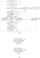
- FIG. 1 illustrates a flow diagram of a pooling-based loop control method according to one embodiment of the present disclosure.
- the method may be applied to an intelligent loop control system of a data center, realizes the control of a central air-conditioning water chilling unit group control product, and meets the functions of automatic startup and shutdown control, automatic frequency adjustment, automatic replacing, information reporting of various devices simultaneously.
- the method specifically includes the following steps:
- step of S 100 operating state data of chilling units is received.
- a data structure of each chilling unit includes a device number, an operating state, a fault state, a manual/automatic state, a health degree, and an operating time. As shown in FIG. 2, FIG. 2 illustrates a schematic diagram of a data structure of a chilling unit.
- the identification number of the chilling unit reflects the position where the chilling unit is located; the operating state reflects whether the chilling unit is in operation; the fault state reflects whether the chilling unit is malfunctioned; the manual/automatic state reflects whether the chilling unit accepts the control of the data center group control system; the health degree reflects the advantages and disadvantages of operating state of the chilling unit (which is different from the malfunctioned chilling unit), and is calculated through a health degree calculation formula, the higher the health degree value, the higher the operation energy efficiency level of the chilling unit.
- the operating time is accumulated running time duration since the chilling unit is started up.
- the operating state, the fault state, and the operating time may be obtained by a data interface layer connected to the chilling unit.
- inoperative chilling units are screened out based on the operating state data.
- a timing polling and a fault polling are performed on the inoperative chilling units to determine a chilling unit to be started up by polling.
- FIG. 3 illustrates a flow diagram of the timing polling, the method specifically includes the following steps:
- the inoperative chilling units are screened out based on the operating state data.
- step of S320 whether there exists a malfunctioned chilling unit in the inoperative chilling units is determined.
- first chilling units to be detected which has no fault and is in an automatic state are screened out from the inoperative chilling units, if there does not exist a malfunctioned chilling unit in the inoperative chilling units.
- the automatic state herein refers to one chilling unit that can implement automatic control of startup and shutdown through a data center.
- FIG. 4 illustrates a detailed flow diagram of the timing polling, replacement is triggered regularly through a preset polling time, so that the timing polling is triggered.
- FIG. 4 illustrates a detailed flow diagram of the timing polling, replacement is triggered regularly through a preset polling time, so that the timing polling is triggered.
- the data structures of the chilling units are read, the inoperative chilling units are searched, and a fault condition of each of the inoperative chilling units is determined.
- a timing polling process is continued to be performed, that is, first chilling units to be detected, which are fault-free and in automatic state, is screened out. If the number of the fault-free chilling unit(s) is less than 1, that is, when the number of the fault-free chilling unit(s) is equal to 0, it indicates that there is no normal chilling unit for polling, an alarm signal is sent out in time to reminder operation and maintenance personnel in order for overhauling.
- chilling unit(s) which is/are fault-free and in automatic state is/are screened (the number of the chilling unit(s) to be started up is N1), then, a health degree H of each chilling unit is obtained through a chilling unit health degree calculation formula.
- a health degree of each of the first chilling unit(s) to be detected is calculated to determine the number of the health chilling unit(s).
- FIG. 5 illustrates a flow diagram of calculation of health degree, the detail of the calculation process of the health degree is described below:
- a step of S341 an actual operation energy efficiency and a theoretical energy efficiency of each of the first chilling unit(s) to be detected under a current operation condition are obtained.
- health degree of the first chilling unit(s) to be detected in a preset period is calculated based on the actual operation energy efficiency and the theoretical operation energy efficiency.
- the theoretical operation energy efficiency COP i of the chilling unit changes with the change of the operation condition
- T evp represents a saturated evaporation temperature
- T cond represents a saturated condensation temperature
- Q represents a load of a chilling unit
- b 0 -b 7 represent preset coefficients.
- the corresponding first chilling unit(s) to be detected is determined as health chilling unit(s) if the health degree is no less than a preset threshold value.
- the energy efficiency value of the chilling unit may be obviously reduced.
- the health degree may be utilized to represent the advantages and disadvantages of the operating state of the chilling unit.
- the actual operation energy efficiency of one certain chilling unit under a certain operation condition I is COP r
- the theoretical operation energy efficiency of the chilling unit under the operation condition is COP i
- a calculation result in a period of time (the calculation period may be set, for example, 1 month), for example, H ⁇ 0.8
- a theoretical operation energy efficiency equation of the chilling unit may be obtained by collecting the operation data of the chilling unit within a period of time.
- the health chilling unit(s) refers to a chilling unit having a relatively higher actual operation energy efficiency level. If H ⁇ 0.8, it can be considered that the actual energy efficiency level of the corresponding chilling unit is relatively lower, however, the operation state of the chilling unit may be maintained, said health chilling unit(s) is/are distinguished from the aforesaid malfunctioned chilling unit.
- a chilling unit to be started up by polling is determined according to the number of the chilling units.
- the determination of the chilling unit to be started up by polling includes following three conditions.
- the number of the first chilling unit(s) to be detected i.e., the health chilling unit
- running time duration of each health chilling unit is compared, and the chilling unit which has the shortest duration of operation is taken as the chilling unit to be started up by polling;
- the preset threshold value is 0.8
- the number of the first chilling unit(s) to be detected is N1
- FIG. 6 illustrates a flow diagram of fault polling which includes following steps: In a step of S361, when one chilling unit in operation malfunctions, inoperative chilling units are screened out based on the operating state data.
- step of S362 whether there exists malfunctioned chilling unit(s) in the inoperative chilling units.
- step of S363 if there does not exist a malfunctioned chilling unit in the inoperative chilling units, second chilling unit(s) to be detected which is/are fault-free and in automatic state is screened out from the malfunctioned chilling unit; In a step of S364, the health degree of each of the second chilling unit(s) to be detected is calculated to determine the number of the health chilling unit(s).
- the chilling unit to be started up by polling is determined according to the number of the chilling unit(s).
- the calculation of the health degree has been described in detail in the aforesaid steps, and is not repeatedly described herein.
- a fault polling mode is entered.
- the data structures of the chilling units are read to determine the inoperative chilling units, and the fault conditions of the inoperative chilling units are determined.
- the number of the fault-free chilling unit(s) is equal to 0, it indicates that there is no normal chilling unit that can be polled, an alarm signal is sent out in time, and the operation and maintenance personnel is notified of overhauling.
- the number of the fault-free chilling unit(s) is greater than or equal to 1
- the chilling unit(s) which is/are fault-free and is/are in automatic state (the number of the chilling unit(s) to be detected is N1) is screened out, then, a health degree index H of each chilling unit is obtained.
- the chilling unit(s) to be detected with health degree of H ⁇ 0.8 For example, if the number N2 of the chilling unit(s) to be detected with health degree of H ⁇ 0.8 is greater than 1, running time durations of the N2 chilling units are continued to be compared, and the chilling unit having shorter duration of operation is selected as the chilling unit to be started up by polling. If the number N2 of the chilling unit(s) to be detected with health degree of H ⁇ 0.8 is equal to 1, this chilling unit is directly selected as the chilling unit to be started up by polling;
- the running time durations of the N1 chilling units are compared, and the chilling unit having shorter duration of operation is selected as the chilling unit to be started up by polling.
- step of S400 the chilling unit in operating state is replaced based on the chilling unit to be started up by polling.
- FIG. 7 illustrates a flow diagram of replacement of the chilling unit in operating state, which specifically includes following steps: In a step of S401, a device number of the chilling unit to be started up by polling is obtained to startup the chilling unit to be started up by polling.
- step of S402 load shedding is performed on the chilling unit that is being in operating state currently or the malfunctioned chilling unit is shut down.
- the chilling unit to be started up by polling is started up firstly, then, the chilling unit in the operating state is shut down, time for replacement is reset, and performing of a next timing polling is waited.
- a device such as a water pump butterfly valve corresponding to the malfunctioned chilling unit is shut down, the fault polling is completed.
- intelligent polling may be performed in the operation process of the intelligent loop control system of the data center, allocation of the various chilling units is balanced, service lives of the various chilling units is averaged, and a problem of system halt caused due to malfunction of one certain chilling unit is avoided by the fault polling.
- a polling-based loop control system is further provided in the embodiments of the present disclosure, in particular, the system is a data center function polling-based loop control system.
- This system is applicable to the control of the central air-conditioning water chilling unit group control product in the data center, and meets the automatic startup and shutdown control, automatic frequency adjustment, and automatic replacement of fault device and information report of the various chilling units, thereby realizing intelligent polling of the intelligent loop control system of the data center during operation, the service lives of the chilling units are averaged. The system halt caused due to malfunction of one certain chilling unit is avoided by fault polling.
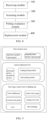
- FIG. 8 illustrates a structural block diagram of a polling-based loop control system, the system may include:
- FIG. 9 illustrates an architecture diagram of an intelligent polling-based loop control system, where the polling evaluation module includes a timing polling module and a fault polling module which belong to a logical judgment layer of the system.
- the system further includes a data interface layer and a device basic logic control layer.
- the data interface layer is configured to be connected to a chilling unit to obtain I/O point positions of all monitoring state information of all monitoring devices of the central air-conditioning system, where, the data interface layer includes two forms of hard interface and communication interface.
- the logical judgment layer determines a polling sequence by analyzing the operating state data of the chilling unit, and is specifically composed of the timing polling module and the fault polling module.
- Intelligent polling logic is added in the full-automatic operation process of the central air-conditioning system, a polling time is set for timing polling.
- one certain chilling unit may be prevented from being operated for a long time, allocation of various chilling units are balanced, and service lives of the chilling units are averaged.
- the fault polling avoids system halt caused due to malfunction of one certain equipment from occurring, and stable operation of the data center server is ensured.
- the device basic logic control layer is used for processing remote manual/automatic startup and shutdown control of a high-efficiency water chilling unit, a chilled water pump, a cooling water pump and a cooling tower fan, and processing valve control of remote manual/automatic switch of a butterfly valve, notification of fault alarm of equipment, etc.
- FIG. 10 illustrates a structural block diagram of another polling-based loop control system, where the polling evaluation module 300 includes a timing polling module 310 and a fault polling module 320.
- the timing polling module 310 may include:
- the health degree calculation module 314 includes:
- COP i b 0 + b 1 T evp + b 2 T cond + b 3 Q + b 4 T evp T cond + b 5 T evp Q + b 6 T cond Q + b 7 Q 2 ;
- COP i b 0 + b 1 T evp + b 2 T cond + b 3 Q + b 4 T evp T cond + b 5 T evp Q + b 6 T cond Q + b 7 Q 2 ;
- T evp represents a saturated evaporation temperature
- T cond represents a saturated condensation temperature
- Q represents a load of a chilling unit.
- the determination module 344 may be configured to determine the corresponding first chilling unit(s) to be detected as the health chilling unit(s), if the health degree is no less than a preset threshold value.
- the detail of the execution process of the fault polling module is similar to the execution process of the timing polling module, and is not repeatedly described herein.
- the replacement module 400 may be specifically configured to: obtain a device number of the chilling unit to be started up by polling to startup the chilling unit to be started up by polling; and perform a load shedding on the chilling unit in the operating state currently or shut down the malfunctioned chilling unit.
- the chilling units that support automatically startup and shutdown control are automatically replaced, the chilling unit to be started (which is selected through the above steps) is started up, the chilling unit that is being in the operating state currently is shut down.
- the chilling unit in the operating state currently is prevented from being operated for a long time, and shortening of the service life of the chilling unit is avoided.
- the chilling unit to be started up by polling is started up to replace the malfunctioned chilling unit, so that a system halt caused due to breakdown of the malfunctioned chilling unit is avoided.
- the butterfly valve of the water pump and other components of the malfunctioned chilling unit are shut off, this is because that, although the malfunctioned chilling unit is faulty, the butterfly valve of the water pump and other components are still in operating state, the butterfly valve of the water pump needs to be shut off.
- the timing polling mechanism and the fault polling mechanism are set to automatically replace the chilling unit in the operating state currently, long-time operation of one same chilling unit is avoided, long-term stable operation of the system is guaranteed, and a problem of system halt caused due to malfunction and shortened service live of one certain chilling unit because that the chilling unit is in long-term operation in the related art is solved.
- the electronic device includes a memory and a processor, the memory stores a computer program, and the processor is configured to execute the computer program to cause the electronic device to perform the aforesaid pooling-based loop control method.
- a readable storage medium stores a computer program instruction, that, when being read and executed by a processor, executes the aforesaid pooling-based loop control method.
- each block in the flow diagrams or the block diagrams may represent a module, a program segment, or a part of codes that contains one or multiple executable instructions for implementing specified logical functions.
- the functions indicated in the block may also be implemented in an order different than the order indicated in the accompanying drawings.
- each block in the block diagrams and/or flow diagrams, and the combination of the blocks in the block diagrams and/or the flow diagrams may also be implemented using a specific hardware based system that perform specified functions or actions, or be implemented using the combination of specific hardware and computer instructions.
- the various functional modules in the various embodiments of the present disclosure may be integrated together to form one independent part.
- the various modules may exist separately, or two or more modules may be integrated to form one independent part.
- the software functional units may be stored in a computer readable storage medium.
- the technical solution of the present disclosure, or the part that is contributable to related art, or a part of the technical solution may be embodied in the form of software product essentially, the computer softer product is stored in a storage medium and includes an instruction that enables a computer device (which may be a personal computer, a server, or a network device, and the like) to execute all or part of steps of methods in the various embodiments of the present disclosure.
- the aforesaid storage medium includes: various mediums capable of storing program codes such as USB flash disk, mobile hard disk, computer memory, ROM (Read-Only Memory), RAM (Random Access Memory), hard disk, optical disk, and the like.
- the present disclosure provides a polling-based loop control method and polling-based loop control system, an electronic device, and a storage medium, which relate to the technical field of automatic control of devices.
- the method includes receiving operation state data of chilling units; screening out inoperative chilling units based on the operating state data; performing a timing polling and a fault polling on the inoperative units to determine a chilling unit to be started up by polling; replacing the chilling unit in operating state based on the chilling unit to be started up by polling.
- the timing polling mechanism and the fault polling mechanism are set to automatically replace the chilling unit that is in operation currently, so that a long-term operation of one single chilling unit is avoided, long-term stable operation of the system is guaranteed, and a problem of system halt caused due to malfunction and shortened service live of one certain chilling unit because that the chilling unit is in long-term operation in the related art is solved.
- the polling-based loop control method, the polling-based loop control system, the electronic device, and the storage medium disclosed in the present disclosure may be reproducible and may be used in various industrial applications.
- the polling-based loop control method, the polling-based loop control system, the electronic device, and the storage medium in the present disclosure may be used in the technical field of automatic control of devices.
Landscapes
- Engineering & Computer Science (AREA)
- General Engineering & Computer Science (AREA)
- Chemical & Material Sciences (AREA)
- Combustion & Propulsion (AREA)
- Mechanical Engineering (AREA)
- Signal Processing (AREA)
- Human Computer Interaction (AREA)
- Physics & Mathematics (AREA)
- Fuzzy Systems (AREA)
- Mathematical Physics (AREA)
- Air Conditioning Control Device (AREA)
- Selective Calling Equipment (AREA)
- Financial Or Insurance-Related Operations Such As Payment And Settlement (AREA)
- Automatic Tape Cassette Changers (AREA)
Abstract
Description
- This application claims priority to
Chinese patent application No. 202111629224.5, filed with CNIPA on December 28, 2021 - The present disclosure relates to the technical field of automatic control of devices, and more particularly, to a pooling-based loop control method, a pooling-based loop control system, an electronic device, and a storage medium.
- Heat productivity of a data center is mainly derived from heat dissipated by information technology (IT) equipment such as a server and a network device in a machine room during operating process of the IT equipment, and heat productivity in four seasons is basically stable, refrigerating output in four seasons is basically constant, too. Thus, the data center requires that a central air conditioner refrigerating system should be operated perennially and stably for a long time. However, generally, when the requirement of refrigerating output of the data center is small, only one or two Chilling units need to be started up to meet the requirement. However, a service life of one single AHU may be reduced when the chilling unit has been in operation for a long time. Once a chilling unit that is being in operation malfunctions, another AHU cannot automatically replace the chilling unit immediately, the central air conditioner refrigerating system may be shut down, and a huge economic loss is caused accordingly.
- A pooling-based loop control method, a pooling-based loop control system, an electronic device, and a storage medium are provided in the embodiments of the present disclosure. A timing polling mechanism and a fault polling mechanism are provided to replace the chilling unit in operation currently automatically. Thus, long-term stable operation of the system is ensured, and a problem of system halt caused due to malfunction and shortened service life of one certain chilling unit in the system due to long-time operation in the related art has been solved.
- A pooling-based loop control method is provided in one embodiment of the present disclosure, the method may include:
- receiving operating state data of chilling units;
- determining a chilling unit to be started up by polling through a timing polling and/or a fault polling; and
- replacing a chilling unit in an operating state based on the chilling unit to be started up by polling.
- In some embodiments, said receiving the operating state data of the chilling unit may include:
generating a data structure of the chilling unit from the operating state data, and reading the data structure of the chilling unit in order for performing the timing polling and the fault polling, the data structure of the chilling unit includes a device number, an operation state, a fault state, a health degree, and an running time. - In the aforesaid implementation process, the operating state data of the chilling units are obtained in real time, and are stored in the form of data structure of chilling unit, which facilitates performing timing polling and fault polling by utilizing the data structures of the chilling units.
- In some embodiments, said determining the chilling unit to be started up by polling through the timing polling and/or the fault polling may include:
- screening out inoperative chilling units based on the operating state data; and
- calculating health degrees of the inoperative chilling units to determine health chilling unit(s); and
- determining the chilling unit to be started up by polling according to the health chilling unit(s).
- In the aforesaid implementation process, the health degree ensures the operation efficiency of the chilling unit. Thus, a health chilling unit may be determined according to the health degree.
- In some embodiments, said calculating the health degrees of the inoperative chilling units to determine the health chilling unit(s) may include:
- obtaining an actual operation energy efficiency and a theoretical operation energy efficiency of each of the inoperative chilling units under a current operation condition; and
- calculating the health degrees of the inoperative chilling units in a preset period based on the actual operation energy efficiency and the theoretical operation energy efficiency.
- In the aforesaid implementation process, a ratio of the actual operation energy efficiency to the theoretical operation energy efficiency is utilized to determine the operation efficiencies of the chilling units, thereby reflecting the health degrees of the chilling units.
- In some embodiments, said performing the timing polling on the inoperative chilling units to determine the chilling unit to be started up by polling may include:
- determining whether there exists a malfunctioned chilling unit in the inoperative chilling units;
- screening out first chilling units to be detected and being fault-free from the inoperative chilling units, if there does not exist the malfunctioned chilling unit in the inoperative chilling units;
- determining a number of health chilling unit(s) in the first chilling units to be detected according to health degrees of the first chilling units to be detected; and
- determining the chilling unit to be started up by polling according to the number of the health chilling unit(s).
- In the aforesaid implementation process, the healthy chilling unit, that is, the chilling unit which has relatively higher operation efficiency, is obtained through timing polling to replace the chilling unit in operation state, shortening of service life of the chilling unit in the operation state, which is caused due to long-term operation, is avoided.
- In some embodiments, said performing the fault polling on the inoperative chilling units to determine the chilling unit to be started up by polling may include:
- screening out, when a chilling unit in an operation state malfunctions, second fault-free chilling units to be detected and being in an automatic state from the inoperative chilling units;
- determining a number of health chilling unit(s) in the second chilling units to be detected according to health degrees of the second chilling units to be detected; and
- determining the chilling unit to be started up by polling according to the number of the health chilling unit(s).
- In the aforesaid implementation process, when the chilling unit in the operation state malfunctions, the fault polling is triggered to determine the chilling unit to be started up by polling for replacing the malfunctioned chilling unit.
- In some embodiments, said determining the number of health chilling unit(s) may include:
determining a chilling unit as a health chilling unit in response to a health degree of the chilling unit is great than or equal to a preset threshold value. - In the aforesaid implementation process, the healthy chilling unit is determined according to the value of the health degree and the threshold value.
- In some embodiments, said determining the chilling unit to be started up by polling according to the number of health chilling unit(s) may include:
- comparing, in response to the number of the health chilling unit(s) is greater than 1, running time(s) of the health chilling unit(s), and taking a chilling unit having a shortest running time as the chilling unit to be started up by polling;
- selecting, in response to the number of the health chilling unit(s) is 1, the health chilling unit as the chilling unit to be started up by polling; or
- comparing, in response to the number of the health chilling unit(s) is 0, running times of the chilling units to be detected, and taking a chilling unit to be detected and having the shortest running time as the chilling unit to be started up by polling.
- In the aforesaid implementation process, the chilling unit to be started up by polling is selected from the first chilling units to be detected and having a health degree equal to or greater than the preset threshold value, and is used for replacing the chilling unit in the operating state.
- In some embodiments, said replacing the chilling unit in the operating state based on the chilling unit to be started up by polling may include:
- starting up the chilling unit to be started up by polling; and
- performing a load shedding on the chilling unit in the operating state currently or shutting down the malfunctioned chilling unit currently.
- A polling-based loop control system is further provided in the embodiments of the present disclosure, the system may include:
- a receiving module configured to receive operating state data of a chilling unit;
- a polling evaluation module configured to determine a chilling unit to be started up by polling through a timing polling and/or a fault polling;
- a replacement module configured to replace a chilling unit in an operating state based on the chilling unit to be started up by polling.
- In some embodiments, the receiving module may be further configured to:
generate data structures of chilling units from the operating state data, and read the data structures of the chilling units for performing the timing polling and the fault polling, the data structures of the chilling units includes a device number (ID), an operation state, a fault state, a health degree, and an running time. - In some embodiments, the polling evaluation module includes a timing polling module and a fault polling module, the timing polling module may include:
- an operation screening module configured to screen out inoperative chilling units based on the operating state data;
- a health degree calculation module configured to calculate health degrees of the inoperative chilling units so as to determine health chilling unit(s);
- a startup determination module configured to determine the chilling unit to be started up by polling according to the health chilling unit(s).
- In some embodiments, the health degree calculation module further includes:
- a parameter acquisition module configured to acquire an actual operation energy efficiency and a theoretical operation energy efficiency of each of the inoperative chilling units under a current operation condition; and
- a health degree determination module configured to calculating the health degrees of the inoperative chilling units in a preset period based on the actual operation energy efficiency and the theoretical operation energy efficiency.
- In some embodiments, the timing polling module further includes a determination module configured to determine whether there exists a malfunctioned chilling unit in the inoperative chilling units; where,
- the chilling unit screening out module is configured to screen out first chilling units to be detected and being fault-free from the inoperative chilling units, if there does not exist the malfunctioned chilling unit in the inoperative chilling units;
- the health degree calculation module is configured to determine a number of health chilling unit(s) in the first chilling units to be detected according to health degrees of the first chilling units to be detected;
- the startup determination module is configured to determine the chilling unit to be started up by polling according to the number of the health chilling unit(s).
- In some embodiments, the determination module is configured to determine a corresponding chilling unit to be detected as a health chilling unit in response to a health degree of the chilling unit to be detected is no less than a preset threshold value.
- In some embodiments, the replacement module is configured to obtain a device number of the chilling unit to be started up by polling so as to start up the chilling unit to be started up by polling, and perform a load shedding on the chilling unit in the operating state currently or shut down the malfunctioned chilling unit.
- An electronic device is further provided in the embodiments of the present disclosure. The electronic device includes a memory and a processor, the memory is configured to store a computer program, the processor is configured to execute the computer program to cause the electronic device to perform the polling-based loop control method according to any one of the aforesaid embodiments.
- A readable storage medium is further provided in the embodiments of the present disclosure. The readable storage medium stores a computer program instruction, that, when read and executed by a processor, performs the pooling-based loop control method according to any one of the aforesaid embodiments.
- In order to explain the technical solutions in the embodiments of the present disclosure more clearly, a brief introduction regarding the accompanying drawings that need to be used for describing the embodiments is given below. It should be understood that the following accompanying drawings only illustrate some embodiments of the present disclosure, and thus should not be taken as limitations to the scope of the claims. For the person of ordinary skill in the art, other relevant drawings may also be obtained according to these drawings without inventive effort.
-
FIG. 1 illustrates a flow diagram of a polling-based loop control method provided in one embodiment of the present disclosure; -
FIG. 2 illustrates a schematic diagram of a data structure of a chilling unit provided in one embodiment of the present disclosure; -
FIG. 3 illustrates a flow diagram of a timing polling provided in one embodiment of the present disclosure; -
FIG. 4 illustrates a specific flow diagram of the timing polling provided in one embodiment of the present disclosure; -
FIG. 5 illustrates a flow diagram of calculation of health degree provided in one embodiment of the present disclosure; -
FIG. 6 illustrates a flow diagram of a fault polling provided in one embodiment of the present disclosure; -
FIG. 7 illustrates a schematic diagram of replacing a chilling unit in an operating state according to one embodiment of the present disclosure; -
FIG. 8 illustrates a schematic structural diagram of a pooling-based loop control system provided in one embodiment of the present disclosure; -
FIG. 9 illustrates an architecture diagram of one intelligent pooling-based loop control system provided in one embodiment of the present disclosure; -
FIG. 10 illustrates an architecture diagram of another intelligent pooling-based loop control system provided in one embodiment of the present disclosure. - Reference numerals are listed below:
100- receiving module; 200- screening module; 300- polling evaluation module; 310-timing polling module; 320- fault polling module; 311-operation screening module; 312-determination module; 313-chilling unit screening module; 314-health degree calculation module; 315-startup determination module; 324-parameter acquisition module; 334-health degree determination module; 344- determination module; 400-replacement module. - The technical solutions in the embodiments of the present disclosure will be described with reference to the accompanying figures in the embodiments of the present disclosure.
- It should be noted that, similar reference numerals and characters represent similar terms in the following accompanying figures. Thus, once an item is defined in one figure, further definition and explanation are unnecessary in the subsequent figures. Furthermore, in the description of the present disclosure, terms such as "first", "second", etc., are only used for distinguishing purposes and cannot be interpreted as indicating or implying relative importance.
- Referring to
FIG. 1, FIG. 1 illustrates a flow diagram of a pooling-based loop control method according to one embodiment of the present disclosure. The method may be applied to an intelligent loop control system of a data center, realizes the control of a central air-conditioning water chilling unit group control product, and meets the functions of automatic startup and shutdown control, automatic frequency adjustment, automatic replacing, information reporting of various devices simultaneously. The method specifically includes the following steps: - In a step of
S 100, operating state data of chilling units is received. - Data structures of the chilling units are generated from the operating state data. A data structure of each chilling unit includes a device number, an operating state, a fault state, a manual/automatic state, a health degree, and an operating time. As shown in
FIG. 2, FIG. 2 illustrates a schematic diagram of a data structure of a chilling unit. Where, the identification number of the chilling unit reflects the position where the chilling unit is located; the operating state reflects whether the chilling unit is in operation; the fault state reflects whether the chilling unit is malfunctioned; the manual/automatic state reflects whether the chilling unit accepts the control of the data center group control system; the health degree reflects the advantages and disadvantages of operating state of the chilling unit (which is different from the malfunctioned chilling unit), and is calculated through a health degree calculation formula, the higher the health degree value, the higher the operation energy efficiency level of the chilling unit. The operating time is accumulated running time duration since the chilling unit is started up. The operating state, the fault state, and the operating time may be obtained by a data interface layer connected to the chilling unit. - In a step of S200, inoperative chilling units are screened out based on the operating state data.
- In a step of S300, a timing polling and a fault polling are performed on the inoperative chilling units to determine a chilling unit to be started up by polling.
- As shown in
FIG. 3, FIG. 3 illustrates a flow diagram of the timing polling, the method specifically includes the following steps: - In a step of S310, the inoperative chilling units are screened out based on the operating state data.
- In a step of S320, whether there exists a malfunctioned chilling unit in the inoperative chilling units is determined.
- In a step of S330, first chilling units to be detected which has no fault and is in an automatic state are screened out from the inoperative chilling units, if there does not exist a malfunctioned chilling unit in the inoperative chilling units.
- The automatic state herein refers to one chilling unit that can implement automatic control of startup and shutdown through a data center.
- As shown in
FIG. 4, FIG. 4 illustrates a detailed flow diagram of the timing polling, replacement is triggered regularly through a preset polling time, so that the timing polling is triggered. In particular, - The data structures of the chilling units are read, the inoperative chilling units are searched, and a fault condition of each of the inoperative chilling units is determined.
- If there exists a malfunctioned chilling unit, whether the number of fault-free chilling unit(s) is greater than or equal to 1, and if the number of the fault-free chilling unit(s) is greater than or equal to 1, a timing polling process is continued to be performed, that is, first chilling units to be detected, which are fault-free and in automatic state, is screened out. If the number of the fault-free chilling unit(s) is less than 1, that is, when the number of the fault-free chilling unit(s) is equal to 0, it indicates that there is no normal chilling unit for polling, an alarm signal is sent out in time to reminder operation and maintenance personnel in order for overhauling.
- When the number of the fault-free chilling unit(s) is greater than or equal to 1, chilling unit(s) which is/are fault-free and in automatic state is/are screened (the number of the chilling unit(s) to be started up is N1), then, a health degree H of each chilling unit is obtained through a chilling unit health degree calculation formula.
- In a step of S340, a health degree of each of the first chilling unit(s) to be detected is calculated to determine the number of the health chilling unit(s).
- As shown in
FIG. 5, FIG. 5 illustrates a flow diagram of calculation of health degree, the detail of the calculation process of the health degree is described below: - In a step of S341, an actual operation energy efficiency and a theoretical energy efficiency of each of the first chilling unit(s) to be detected under a current operation condition are obtained.
- In a step of S342, health degree of the first chilling unit(s) to be detected in a preset period is calculated based on the actual operation energy efficiency and the theoretical operation energy efficiency. The health degree is expressed as:

where, H represents the health degree, ∑COPr represents the sum of the actual operating energy efficiencies during a time duration of the preset period, and ∑COPi represents the sum of the theoretical operating energy efficiencies during the time duration of the preset period. - Due to the fact that the theoretical operation energy efficiency COPi of the chilling unit changes with the change of the operation condition, the theoretical operation energy efficiency COPi and the main operation parameters of the chilling units may be obtained through a following regression equation, which is expressed as:

- In a step of S343, the corresponding first chilling unit(s) to be detected is determined as health chilling unit(s) if the health degree is no less than a preset threshold value.
- Due to internal fault problems including condenser fouling, refrigerant leakage, reduction of motor efficiency of compressor in the operation process of the water chilling unit, when an internal fault problem occurs in the chilling unit, the energy efficiency value of the chilling unit may be obviously reduced. Thus, the health degree may be utilized to represent the advantages and disadvantages of the operating state of the chilling unit.
- Assuming that the actual operation energy efficiency of one certain chilling unit under a certain operation condition I is COPr , the theoretical operation energy efficiency of the chilling unit under the operation condition is COPi , and a calculation result in a period of time (the calculation period may be set, for example, 1 month), for example, H<0.8, it is considered that the energy efficiency of the chilling unit is seriously attenuated, a serious fault occurs in the chilling unit, and a property management staff need to perform maintenance.
- During an initial stage of operation of the central air-conditioning system in the data center, a theoretical operation energy efficiency equation of the chilling unit may be obtained by collecting the operation data of the chilling unit within a period of time.
- Herein, the health chilling unit(s) refers to a chilling unit having a relatively higher actual operation energy efficiency level. If H<0.8, it can be considered that the actual energy efficiency level of the corresponding chilling unit is relatively lower, however, the operation state of the chilling unit may be maintained, said health chilling unit(s) is/are distinguished from the aforesaid malfunctioned chilling unit.
- In a step of S350, a chilling unit to be started up by polling is determined according to the number of the chilling units.
- The determination of the chilling unit to be started up by polling includes following three conditions.
- If the number of the first chilling unit(s) to be detected (i.e., the health chilling unit) with the health degree greater than or equal to the preset threshold value is greater than 1, running time duration of each health chilling unit is compared, and the chilling unit which has the shortest duration of operation is taken as the chilling unit to be started up by polling;
- If the number of the first chilling unit(s) to be detected with the health degree greater than or equal to the preset threshold value is 1, the health chilling unit is taken as the chilling unit to be started up by polling;
- If the number of the first chilling unit(s) to be detected with the health degree greater than or equal to the preset threshold value is 0, the running time durations of the first chilling unit(s) to be detected are compared, and the first chilling unit(s) to be detected with the shortest duration of operation is used as the chilling unit to be started up by polling.
- As an example, the preset threshold value is 0.8, the number of the first chilling unit(s) to be detected is N1,
- if the number N2 of the chilling units(s) having the health degree of H≥0.8 is greater than 1, running time durations of the N2 chilling units are compared, and one chilling unit having the shorter running time is used as the chilling unit to be started up by polling;
- if the number N2 of the chilling unit(s) having the health degree of H≥0.8 is 1, this chilling unit is directly selected as the chilling unit to be started up by polling;
- If the number N2 of the chilling unit(s) having the health degree of H≥0.8 is 0, the running time durations of the N1 chilling units are compared, and the chilling unit having shorter duration of operation is selected as a chilling unit to be started up by polling.
- Regarding fault polling, as shown in
FIG. 6, FIG. 6 illustrates a flow diagram of fault polling which includes following steps:
In a step of S361, when one chilling unit in operation malfunctions, inoperative chilling units are screened out based on the operating state data. - In a step of S362, whether there exists malfunctioned chilling unit(s) in the inoperative chilling units.
- In a step of S363, if there does not exist a malfunctioned chilling unit in the inoperative chilling units, second chilling unit(s) to be detected which is/are fault-free and in automatic state is screened out from the malfunctioned chilling unit;
In a step of S364, the health degree of each of the second chilling unit(s) to be detected is calculated to determine the number of the health chilling unit(s). - In a step of S365, the chilling unit to be started up by polling is determined according to the number of the chilling unit(s).
- Regarding the calculation of the health degree, the calculation of the health degree has been described in detail in the aforesaid steps, and is not repeatedly described herein.
- When a system failure is detected, a fault polling mode is entered. The data structures of the chilling units are read to determine the inoperative chilling units, and the fault conditions of the inoperative chilling units are determined. When the number of the fault-free chilling unit(s) is equal to 0, it indicates that there is no normal chilling unit that can be polled, an alarm signal is sent out in time, and the operation and maintenance personnel is notified of overhauling. When the number of the fault-free chilling unit(s) is greater than or equal to 1, the chilling unit(s) which is/are fault-free and is/are in automatic state (the number of the chilling unit(s) to be detected is N1) is screened out, then, a health degree index H of each chilling unit is obtained.
- For example, if the number N2 of the chilling unit(s) to be detected with health degree of H≥0.8 is greater than 1, running time durations of the N2 chilling units are continued to be compared, and the chilling unit having shorter duration of operation is selected as the chilling unit to be started up by polling.
If the number N2 of the chilling unit(s) to be detected with health degree of H ≥ 0.8 is equal to 1, this chilling unit is directly selected as the chilling unit to be started up by polling; - If the number N2 of the chilling unit(s) to be detected with health degree of H ≥ 0.8 is equal to 0, the running time durations of the N1 chilling units are compared, and the chilling unit having shorter duration of operation is selected as the chilling unit to be started up by polling.
- In a step of S400, the chilling unit in operating state is replaced based on the chilling unit to be started up by polling.
- As shown in
FIG. 7, FIG. 7 illustrates a flow diagram of replacement of the chilling unit in operating state, which specifically includes following steps:
In a step of S401, a device number of the chilling unit to be started up by polling is obtained to startup the chilling unit to be started up by polling. - In a step of S402, load shedding is performed on the chilling unit that is being in operating state currently or the malfunctioned chilling unit is shut down.
- In particular, regarding the timing polling, after the chilling unit to be started up by polling is obtained, the chilling unit to be started up by polling is started up firstly, then, the chilling unit in the operating state is shut down, time for replacement is reset, and performing of a next timing polling is waited.
- Regarding the fault polling, after the chilling unit to be started up by polling is determined, a device such as a water pump butterfly valve corresponding to the malfunctioned chilling unit is shut down, the fault polling is completed.
- According to this method, intelligent polling may be performed in the operation process of the intelligent loop control system of the data center, allocation of the various chilling units is balanced, service lives of the various chilling units is averaged, and a problem of system halt caused due to malfunction of one certain chilling unit is avoided by the fault polling.
- A polling-based loop control system is further provided in the embodiments of the present disclosure, in particular, the system is a data center function polling-based loop control system. This system is applicable to the control of the central air-conditioning water chilling unit group control product in the data center, and meets the automatic startup and shutdown control, automatic frequency adjustment, and automatic replacement of fault device and information report of the various chilling units, thereby realizing intelligent polling of the intelligent loop control system of the data center during operation, the service lives of the chilling units are averaged. The system halt caused due to malfunction of one certain chilling unit is avoided by fault polling. As shown in
FIG. 8, FIG. 8 illustrates a structural block diagram of a polling-based loop control system, the system may include: - a
receiving module 100 which may be configured to receive operating state data of a chilling unit; - a
screening module 200 which may be configured to screen out inoperative chilling units based on the operating state data; - a
polling evaluation module 300 which may be configured to perform a timing polling and a fault polling on the inoperative chilling units to determine a chilling unit to be started up by polling; - a
replacement module 400 which may be configured to replace a chilling unit in an operating state based on the chilling unit to be started up by polling. - As shown in
FIG. 9, FIG. 9 illustrates an architecture diagram of an intelligent polling-based loop control system, where the polling evaluation module includes a timing polling module and a fault polling module which belong to a logical judgment layer of the system. In addition, the system further includes a data interface layer and a device basic logic control layer. - The data interface layer is configured to be connected to a chilling unit to obtain I/O point positions of all monitoring state information of all monitoring devices of the central air-conditioning system, where, the data interface layer includes two forms of hard interface and communication interface.
- The logical judgment layer determines a polling sequence by analyzing the operating state data of the chilling unit, and is specifically composed of the timing polling module and the fault polling module. Intelligent polling logic is added in the full-automatic operation process of the central air-conditioning system, a polling time is set for timing polling. Thus, one certain chilling unit may be prevented from being operated for a long time, allocation of various chilling units are balanced, and service lives of the chilling units are averaged. The fault polling avoids system halt caused due to malfunction of one certain equipment from occurring, and stable operation of the data center server is ensured.
- The device basic logic control layer is used for processing remote manual/automatic startup and shutdown control of a high-efficiency water chilling unit, a chilled water pump, a cooling water pump and a cooling tower fan, and processing valve control of remote manual/automatic switch of a butterfly valve, notification of fault alarm of equipment, etc.
- As shown in
FIG. 10, FIG. 10 illustrates a structural block diagram of another polling-based loop control system, where thepolling evaluation module 300 includes atiming polling module 310 and afault polling module 320. Thetiming polling module 310 may include: - an
operation screening module 311 which may be configured to screen out inoperative chilling units based on the operating state data. - a
determination module 312 which may be configured to determine whether there exists a malfunctioned chilling unit in the inoperative chilling units. - a chilling
unit screening module 313 which may be configured to screen out first chilling units to be detected which are fault-free and are in automatic state from the inoperative chilling units, if there does not exist a malfunctioned chilling unit in the inoperative chilling units; - a health degree calculation module 314 which may be configured to calculate the health degree of each of the first chilling units to be detected to determine a number of health chilling unit(s);
- a
startup determination module 315 which may be configured to determine the chilling unit to be started up by polling according to the number of the health chilling unit(s). - Regarding the detail of the calculation of health degree, the health degree calculation module 314 includes:
- a
parameter acquisition module 324 which may be configured to obtain an actual operation energy efficiency and a theoretical operation energy efficiency of the first chilling units to be detected under a current operating condition. - a health
degree determination module 334 which may be configured to calculate the health degree of the first chilling units to be detected in a preset period based on the actual operation energy efficiency and the theoretical operation energy efficiency. The health degree is expressed as:

- where, H represents the health degree, ∑COPr represents the sum of the actual operating energy efficiencies during a time duration of the preset period, and ∑COPi represents the sum of the theoretical operating energy efficiencies during the time duration of the preset period.
- COPi = b 0 + b 1 Tevp + b 2 Tcond + b 3 Q + b 4 TevpTcond + b 5 TevpQ+ b 6 TcondQ + b 7 Q 2;
Where, COPi = b 0 + b 1 Tevp + b 2 Tcond + b 3 Q + b 4 TevpTcond + b 5 TevpQ + b 6 TcondQ + b 7 Q 2;
where, Tevp represents a saturated evaporation temperature, Tcond represents a saturated condensation temperature, Q represents a load of a chilling unit. - The
determination module 344 may be configured to determine the corresponding first chilling unit(s) to be detected as the health chilling unit(s), if the health degree is no less than a preset threshold value. - The detail of the execution process of the fault polling module is similar to the execution process of the timing polling module, and is not repeatedly described herein.
- The
replacement module 400 may be specifically configured to:
obtain a device number of the chilling unit to be started up by polling to startup the chilling unit to be started up by polling; and perform a load shedding on the chilling unit in the operating state currently or shut down the malfunctioned chilling unit. - During this process, the chilling units that support automatically startup and shutdown control are automatically replaced, the chilling unit to be started (which is selected through the above steps) is started up, the chilling unit that is being in the operating state currently is shut down. Thus, the chilling unit in the operating state currently is prevented from being operated for a long time, and shortening of the service life of the chilling unit is avoided. If malfunction of one chilling unit occurs, the chilling unit to be started up by polling is started up to replace the malfunctioned chilling unit, so that a system halt caused due to breakdown of the malfunctioned chilling unit is avoided. Then, the butterfly valve of the water pump and other components of the malfunctioned chilling unit are shut off, this is because that, although the malfunctioned chilling unit is faulty, the butterfly valve of the water pump and other components are still in operating state, the butterfly valve of the water pump needs to be shut off.
- The timing polling mechanism and the fault polling mechanism are set to automatically replace the chilling unit in the operating state currently, long-time operation of one same chilling unit is avoided, long-term stable operation of the system is guaranteed, and a problem of system halt caused due to malfunction and shortened service live of one certain chilling unit because that the chilling unit is in long-term operation in the related art is solved.
- An electronic device is further provided in the embodiments of the present disclosure, the electronic device includes a memory and a processor, the memory stores a computer program, and the processor is configured to execute the computer program to cause the electronic device to perform the aforesaid pooling-based loop control method.
- A readable storage medium is further provided in one embodiment of the present disclosure, the readable storage medium stores a computer program instruction, that, when being read and executed by a processor, executes the aforesaid pooling-based loop control method.
- In these embodiments provided in the present disclosure, it should be understood that the disclosed devices and methods may also be implemented in other manners. The device embodiments described above are only illustrative. For example, the flow diagrams and the block diagrams in the accompanying drawings illustrate the possible architectures, functions, and operations of the devices, methods, and computer program products according to the plurality of embodiments disclosed in the present disclosure. At this point, each block in the flow diagrams or the block diagrams may represent a module, a program segment, or a part of codes that contains one or multiple executable instructions for implementing specified logical functions. It should also be noted that, in some alternative implementations, the functions indicated in the block may also be implemented in an order different than the order indicated in the accompanying drawings. For example, two consecutive blocks may actually be performed in parallel. Sometimes, the two consecutive blocks may also be executed in an opposite order. The order of execution of the blocks depends on the function involved in the blocks. It should also be noted that, each block in the block diagrams and/or flow diagrams, and the combination of the blocks in the block diagrams and/or the flow diagrams may also be implemented using a specific hardware based system that perform specified functions or actions, or be implemented using the combination of specific hardware and computer instructions.
- In addition, the various functional modules in the various embodiments of the present disclosure may be integrated together to form one independent part. Alternatively, the various modules may exist separately, or two or more modules may be integrated to form one independent part.
- If the functionalities are achieved in the form of software functional units, and are sold or used as an independent product, the software functional units may be stored in a computer readable storage medium. Based on this understanding, the technical solution of the present disclosure, or the part that is contributable to related art, or a part of the technical solution may be embodied in the form of software product essentially, the computer softer product is stored in a storage medium and includes an instruction that enables a computer device (which may be a personal computer, a server, or a network device, and the like) to execute all or part of steps of methods in the various embodiments of the present disclosure. The aforesaid storage medium includes: various mediums capable of storing program codes such as USB flash disk, mobile hard disk, computer memory, ROM (Read-Only Memory), RAM (Random Access Memory), hard disk, optical disk, and the like.
- Only some optional embodiments of the present disclosure are described above, and these embodiments are not intended to limit the protection scope of the present disclosure. It is obvious to the person of ordinary skill in the art that, various modifications and changes may be made in the present disclosure. Any modification, equivalent replacement, improvement, and the like, which are made within the spirit and the principle of the present disclosure, should all be included in the protection scope of the present disclosure. It should be noted that, similar reference numerals and characters represent similar terms in the following figures. Thus, once one item is defined in one figure, there is no need to further define and explain the item in the subsequent figures.
- The aforesaid embodiments are only some specific embodiments of the present disclosure. However, the protection scope of the present disclosure is not limited by these embodiments. Any change or replacement which is conceivable to the one of ordinary skill in the art who is familiar with the technical field of the present disclosure within the technical scope of the present disclosure, should all be included in the protection scope of the present disclosure. Thus, the protection scope of the present disclosure should be determined by the protection scope of the claims.
- It should also be noted that, in the description of the present disclosure, the terms which represents relationship such as the first and the second are merely used to distinguish one entity or one operation from another entity or another operation without necessarily requiring or implying that there is any such actual relationship or order between these entities or operations. Moreover, terms such as "comprising", "including" or any other variation are intended to cover a non-exclusive inclusion, so that a process, a method, goods, or a device which includes a series of elements not only include the elements, but also include other elements that are not expressly listed, or include the elements inherent to such process, method, goods, or device. In the condition of no further limitations, an element which is defined by a sentence "includes one ..." does not exclude a presence of additional identical elements in the process, the method, the goods, and the device which include the elements.
- The present disclosure provides a polling-based loop control method and polling-based loop control system, an electronic device, and a storage medium, which relate to the technical field of automatic control of devices. The method includes receiving operation state data of chilling units; screening out inoperative chilling units based on the operating state data; performing a timing polling and a fault polling on the inoperative units to determine a chilling unit to be started up by polling; replacing the chilling unit in operating state based on the chilling unit to be started up by polling. The timing polling mechanism and the fault polling mechanism are set to automatically replace the chilling unit that is in operation currently, so that a long-term operation of one single chilling unit is avoided, long-term stable operation of the system is guaranteed, and a problem of system halt caused due to malfunction and shortened service live of one certain chilling unit because that the chilling unit is in long-term operation in the related art is solved.
- In addition, it can be understood that, the polling-based loop control method, the polling-based loop control system, the electronic device, and the storage medium disclosed in the present disclosure may be reproducible and may be used in various industrial applications. For example, the polling-based loop control method, the polling-based loop control system, the electronic device, and the storage medium in the present disclosure may be used in the technical field of automatic control of devices.
Claims (18)
- A pooling-based loop control method, characterized in that, the method comprises:receiving operating state data of chilling units;determining a chilling unit to be started up by polling through a timing polling and/or a fault polling; andreplacing a chilling unit in an operating state based on the chilling unit to be started up by polling.
- The pooling-based loop control method according to claim 1, wherein said receiving the operating state data of the chilling unit comprises:
generating a data structure of the chilling unit from the operating state data, and reading the data structure of the chilling unit in order for performing the timing polling and the fault polling, wherein the data structure of the chilling unit comprises a device number, an operation state, a fault state, a health degree, and an running time. - The pooling-based loop control method according to claim 1 or 2, wherein said determining the chilling unit to be started up by polling through the timing polling and/or the fault polling comprises:screening out inoperative chilling units based on the operating state data; andcalculating health degrees of the inoperative chilling units to determine health chilling unit(s); anddetermining the chilling unit to be started up by polling according to the health chilling unit(s).
- The pooling-based loop control method according to claim 3, wherein said calculating the health degrees of the inoperative chilling units to determine the health chilling unit(s) comprises:obtaining an actual operation energy efficiency and a theoretical operation energy efficiency of each of the inoperative chilling units under a current operation condition; andcalculating the health degrees in a preset period based on the actual operation energy efficiency and the theoretical operation energy efficiency.
- The pooling-based loop control method according to claim 3 or 4, wherein said performing the timing polling on the inoperative chilling units to determine the chilling unit to be started up by polling comprises:determining whether there exists a malfunctioned chilling unit in the inoperative chilling units;screening out first chilling units to be detected and being fault-free from the inoperative chilling units, if there does not exist the malfunctioned chilling unit in the inoperative chilling units;determining a number of health chilling unit(s) in the first chilling units to be detected according to health degrees of the first chilling units to be detected; anddetermining the chilling unit to be started up by polling according to the number of the health chilling unit(s).
- The pooling-based loop control method according to claim 3 or 4, wherein said performing the fault polling on the inoperative chilling units to determine the chilling unit to be started up by polling comprises:screening out, when a chilling unit in an operation state malfunctions, second chilling units to be detected and being fault-free and in an automatic state from the inoperative chilling units;determining a number of health chilling unit(s) in the second chilling units to be detected according to health degrees of the second chilling units to be detected; anddetermining the chilling unit to be started up by polling according to the number of the health chilling unit(s).
- The pooling-based loop control method according to claim 5 or 6, wherein said determining the number of health chilling unit(s) comprises:
determining a chilling unit as a health chilling unit in response to a health degree of the chilling unit is great than or equal to a preset threshold value. - The pooling-based loop control method according to claim 5 or 6, wherein said determining the chilling unit to be started up by polling according to the number of fault-free chilling unit(s) comprises:comparing, in response to the number of the health chilling unit(s) is greater than 1, running time of each of the health chilling units, and taking a chilling unit having a shortest running time as the chilling unit to be started up by polling;selecting, in response to the number of the health chilling unit(s) is 1, the health chilling unit as the chilling unit to be started up by polling; orcomparing, in response to the number of the health chilling unit(s) is 0, running time of each of the chilling units to be detected, and taking a chilling unit to be detected and having the shortest running time as the chilling unit to be started up by polling.
- The pooling-based loop control method according to any one of claims 1 to 8, wherein said replacing the chilling unit in the operating state based on the chilling unit to be started up by polling comprises:starting up the chilling unit to be started up by polling; andperforming a load shedding on the chilling unit in the operating state currently or shutting down the malfunctioned chilling unit.
- A polling-based loop control system, characterized in that, the system comprises:a receiving module configured to receive operating state data of a chilling unit;a polling evaluation module configured to determine a chilling unit to be started up by polling through a timing polling and/or a fault polling;a replacement module configured to replace a chilling unit in an operating state based on the chilling unit to be started up by polling.
- The polling-based loop control system according to claim 10, wherein the receiving module is further configured to:
generate data structures of chilling units from the operating state data, and read the data structures of the chilling units for performing the timing polling and the fault polling, the data structures of the chilling units comprises a device number (ID), an operation state, a fault state, a health degree, and a running time. - The polling-based loop control system according to claim 10 or 11, wherein the polling evaluation module comprises a timing polling module and a fault polling module, the timing polling module comprises:an operation screening module configured to screen out inoperative chilling units based on the operating state data; anda health degree calculation module configured to calculate health degrees of the inoperative chilling units so as to determine health chilling unit(s); anda startup determination module configured to determine the chilling unit to be started up by polling according to the health chilling unit(s).
- The polling-based loop control system according to claim 12, wherein the health degree calculation module further comprises:a parameter acquisition module configured to acquire an actual operation energy efficiency and a theoretical operation energy efficiency of each of the inoperative chilling units under a current operation condition; anda health degree determination module configured to calculating the health degrees in a preset period based on the actual operation energy efficiency and the theoretical operation energy efficiency.
- The polling-based loop control system according to claim 12 or 13, wherein the timing polling module further comprises a determination module configured to determine whether there exists a malfunctioned chilling unit in the inoperative chilling units; wherein,the chilling unit screening module is configured to screen out first chilling units to be detected and being fault-free from the inoperative chilling units, if there does not exist the malfunctioned chilling unit in the inoperative chilling units;the health degree calculation module is configured to determine a number of health chilling unit(s) in the first chilling units to be detected according to health degrees of the first chilling units to be detected;the startup determination module is configured to determine the chilling unit to be started up by polling according to the number of the health chilling unit(s).
- The polling-based loop control system according to claim 14, wherein the determination module is configured to determine a corresponding chilling unit to be detected as a health chilling unit if a health degree of the chilling unit to be detected is no less than a preset threshold value.
- The polling-based loop control system according to any one of claims 10 to 15, wherein the replacement module is configured to obtain an identification (ID) of the chilling unit to be started up by polling to start up the chilling unit to be started up by polling, and perform a load shedding on the chilling unit in the operating state currently or shut down the malfunctioned chilling unit.
- An electronic device, wherein the electronic device comprises a memory and a processor, wherein the memory is configured to store a computer program, and the processor is configured to execute the computer program to cause the electronic device to perform the polling-based loop control method according to any one of claims 1 to 9.
- A readable storage medium, wherein the readable storage medium stores a computer program instruction, that, when being read and executed by a processor, performs the pooling-based loop control method according to any one of claims 1 to 9.
Applications Claiming Priority (2)
| Application Number | Priority Date | Filing Date | Title |
|---|---|---|---|
| CN202111629224.5A CN114322213A (en) | 2021-12-28 | 2021-12-28 | A polling environment control method, system, electronic device and storage medium |
| PCT/CN2022/136335 WO2023124781A1 (en) | 2021-12-28 | 2022-12-02 | Polling loop control method and system, electronic device, and storage medium |
Publications (2)
| Publication Number | Publication Date |
|---|---|
| EP4375584A1 true EP4375584A1 (en) | 2024-05-29 |
| EP4375584A4 EP4375584A4 (en) | 2025-01-15 |
Family
ID=81014970
Family Applications (1)
| Application Number | Title | Priority Date | Filing Date |
|---|---|---|---|
| EP22914036.3A Pending EP4375584A4 (en) | 2021-12-28 | 2022-12-02 | Polling loop control method and system, electronic device, and storage medium |
Country Status (4)
| Country | Link |
|---|---|
| US (1) | US20250093062A1 (en) |
| EP (1) | EP4375584A4 (en) |
| CN (1) | CN114322213A (en) |
| WO (1) | WO2023124781A1 (en) |
Families Citing this family (2)
| Publication number | Priority date | Publication date | Assignee | Title |
|---|---|---|---|---|
| CN114322213A (en) * | 2021-12-28 | 2022-04-12 | 上海美控智慧建筑有限公司 | A polling environment control method, system, electronic device and storage medium |
| CN115930377B (en) * | 2022-12-12 | 2024-12-13 | 珠海格力电器股份有限公司 | Air conditioning communication control method, device, air conditioning unit and remote control equipment |
Family Cites Families (17)
| Publication number | Priority date | Publication date | Assignee | Title |
|---|---|---|---|---|
| JP2001157276A (en) * | 1999-11-30 | 2001-06-08 | Matsushita Electric Works Ltd | Communication processing method in control system |
| CN105611814B (en) * | 2016-03-22 | 2018-02-16 | 紫光华山科技服务有限公司 | A kind of refrigeration station of data center team control control system and control method |
| CN106765867B (en) * | 2016-11-14 | 2018-12-07 | 珠海格力电器股份有限公司 | Control method and system for air conditioner water chilling unit |
| FR3070659B1 (en) * | 2017-09-05 | 2020-01-10 | Alstom Transport Technologies | METHOD FOR SUPERVISING A AIR CONDITIONING SYSTEM OF A RAIL VEHICLE AND RAIL VEHICLE COMPRISING AN AIR CONDITIONING SYSTEM IMPLEMENTING THIS METHOD |
| CN107975909B (en) * | 2017-11-22 | 2020-02-14 | 珠海格力电器股份有限公司 | Air conditioner standby machine starting control method and device and computer readable storage medium |
| CN108488969A (en) * | 2018-03-23 | 2018-09-04 | 北京百度网讯科技有限公司 | Control method and control device for handpiece Water Chilling Units |
| CN108613327B (en) * | 2018-03-30 | 2019-10-08 | 珠海格力电器股份有限公司 | Combined alternate operation method and device of outdoor unit and multi-split system |
| CN110737214B (en) * | 2018-07-18 | 2024-11-26 | 开利公司 | Analysis-based chiller ranking |
| WO2020136675A1 (en) * | 2018-12-26 | 2020-07-02 | Bert Labs Private Limited | System and method for improving the energy management of hvac equipment |
| CN110147086A (en) * | 2019-04-29 | 2019-08-20 | 上海外高桥第二发电有限责任公司 | The determination method and system of the health status of online equipment in power plant |
| CN110108002B (en) * | 2019-05-31 | 2021-02-26 | 珠海格力电器股份有限公司 | Outdoor unit operation control method and device for improving operation energy efficiency and stability |
| CN110319540A (en) * | 2019-06-28 | 2019-10-11 | 广东志高暖通设备股份有限公司 | A kind of Modular multi-connection control method of dynamic adjustment |
| CN111306706B (en) * | 2019-10-10 | 2021-11-02 | 珠海派诺科技股份有限公司 | Air conditioner linkage control method and system |
| CN113537652A (en) * | 2020-03-31 | 2021-10-22 | 厦门邑通软件科技有限公司 | Equipment health monitoring and early warning method, system, storage medium and equipment |
| CN113405223A (en) * | 2021-06-23 | 2021-09-17 | 苏州智而卓数字科技有限公司 | Cold machine number control method based on GRNN and control system thereof |
| CN113654201B (en) * | 2021-08-10 | 2023-04-07 | 青岛海信日立空调系统有限公司 | Central air-conditioning control system |
| CN114322213A (en) * | 2021-12-28 | 2022-04-12 | 上海美控智慧建筑有限公司 | A polling environment control method, system, electronic device and storage medium |
-
2021
- 2021-12-28 CN CN202111629224.5A patent/CN114322213A/en active Pending
-
2022
- 2022-12-02 WO PCT/CN2022/136335 patent/WO2023124781A1/en not_active Ceased
- 2022-12-02 EP EP22914036.3A patent/EP4375584A4/en active Pending
- 2022-12-02 US US18/293,268 patent/US20250093062A1/en active Pending
Also Published As
| Publication number | Publication date |
|---|---|
| WO2023124781A1 (en) | 2023-07-06 |
| EP4375584A4 (en) | 2025-01-15 |
| CN114322213A (en) | 2022-04-12 |
| US20250093062A1 (en) | 2025-03-20 |
Similar Documents
| Publication | Publication Date | Title |
|---|---|---|
| KR102366961B1 (en) | Method and apparatus for managing heating venilation and air conditioning | |
| CA3229405C (en) | Automatic repair of computing devices in a data center | |
| US20200200420A1 (en) | Building management system with central plantroom dashboards | |
| EP4734020A1 (en) | Energy consumption grading optimization method, computer device, and storage medium | |
| US12332149B2 (en) | Managing the effectiveness of repairs in refrigeration assets | |
| US20200162354A1 (en) | Building system with a time correlated reliability data stream | |
| US20250093062A1 (en) | Method and system for polling-based loop control, electronic device and storage medium | |
| US10372567B2 (en) | Automatic fault detection and diagnosis in complex physical systems | |
| US20160203036A1 (en) | Machine learning-based fault detection system | |
| EP4309013B1 (en) | Systems and methods for determining equipment energy waste | |
| US20190195525A1 (en) | Method and apparatus for operating heating and cooling equipment via a network | |
| US20240185122A1 (en) | Monitoring and control system for connected building equipment with fault prediction and predictive maintenance | |
| KR102393602B1 (en) | Air-conditioner System and Method thereof | |
| US10607476B1 (en) | Building security system with site risk reduction | |
| CN107461881B (en) | Refrigeration host energy efficiency diagnosis method and system for hospital air conditioner room | |
| CA2933904C (en) | Managing the effectiveness of repairs in refrigeration assets | |
| KR101259803B1 (en) | Unifying Control System for Multi-Airconditioner and Error control method thereof | |
| CN110750427A (en) | Data center equipment inspection method and system | |
| CN117308505B (en) | Intelligent maintenance and decision support method suitable for commercial refrigerator | |
| KR102234054B1 (en) | Risk assessment device, risk assessment system, risk assessment method, risk assessment program and data structure | |
| KR20130022295A (en) | Apparatus and method for driving an air conditioner | |
| CN108764715A (en) | Equipment operation technical capability evaluation system and method | |
| US20250264378A1 (en) | Systems and methods for predictive maintenance of equipment | |
| JP7528046B2 (en) | Anomaly detection device and anomaly detection method | |
| US20250015591A1 (en) | Energy control and predictive model of building automation systems |
Legal Events
| Date | Code | Title | Description |
|---|---|---|---|
| STAA | Information on the status of an ep patent application or granted ep patent |
Free format text: STATUS: THE INTERNATIONAL PUBLICATION HAS BEEN MADE |
|
| PUAI | Public reference made under article 153(3) epc to a published international application that has entered the european phase |
Free format text: ORIGINAL CODE: 0009012 |
|
| STAA | Information on the status of an ep patent application or granted ep patent |
Free format text: STATUS: REQUEST FOR EXAMINATION WAS MADE |
|
| 17P | Request for examination filed |
Effective date: 20240221 |
|
| AK | Designated contracting states |
Kind code of ref document: A1 Designated state(s): AL AT BE BG CH CY CZ DE DK EE ES FI FR GB GR HR HU IE IS IT LI LT LU LV MC ME MK MT NL NO PL PT RO RS SE SI SK SM TR |
|
| A4 | Supplementary search report drawn up and despatched |
Effective date: 20241212 |
|
| RIC1 | Information provided on ipc code assigned before grant |
Ipc: F24F 11/70 20180101ALI20241209BHEP Ipc: F24F 11/49 20180101AFI20241209BHEP |
|
| DAV | Request for validation of the european patent (deleted) | ||
| DAX | Request for extension of the european patent (deleted) |