EP4375529B1 - Clutch device - Google Patents
Clutch device Download PDFInfo
- Publication number
- EP4375529B1 EP4375529B1 EP23206874.2A EP23206874A EP4375529B1 EP 4375529 B1 EP4375529 B1 EP 4375529B1 EP 23206874 A EP23206874 A EP 23206874A EP 4375529 B1 EP4375529 B1 EP 4375529B1
- Authority
- EP
- European Patent Office
- Prior art keywords
- cam
- outer ring
- inner ring
- peripheral portion
- ring portion
- Prior art date
- Legal status (The legal status is an assumption and is not a legal conclusion. Google has not performed a legal analysis and makes no representation as to the accuracy of the status listed.)
- Active
Links
Images






Classifications
-
- F—MECHANICAL ENGINEERING; LIGHTING; HEATING; WEAPONS; BLASTING
- F16—ENGINEERING ELEMENTS AND UNITS; GENERAL MEASURES FOR PRODUCING AND MAINTAINING EFFECTIVE FUNCTIONING OF MACHINES OR INSTALLATIONS; THERMAL INSULATION IN GENERAL
- F16D—COUPLINGS FOR TRANSMITTING ROTATION; CLUTCHES; BRAKES
- F16D41/00—Freewheels or freewheel clutches
- F16D41/12—Freewheels or freewheel clutches with hinged pawl co-operating with teeth, cogs, or the like
- F16D41/16—Freewheels or freewheel clutches with hinged pawl co-operating with teeth, cogs, or the like the action being reversible
-
- F—MECHANICAL ENGINEERING; LIGHTING; HEATING; WEAPONS; BLASTING
- F16—ENGINEERING ELEMENTS AND UNITS; GENERAL MEASURES FOR PRODUCING AND MAINTAINING EFFECTIVE FUNCTIONING OF MACHINES OR INSTALLATIONS; THERMAL INSULATION IN GENERAL
- F16D—COUPLINGS FOR TRANSMITTING ROTATION; CLUTCHES; BRAKES
- F16D23/00—Details of mechanically-actuated clutches not specific for one distinct type
- F16D23/12—Mechanical clutch-actuating mechanisms arranged outside the clutch as such
-
- F—MECHANICAL ENGINEERING; LIGHTING; HEATING; WEAPONS; BLASTING
- F16—ENGINEERING ELEMENTS AND UNITS; GENERAL MEASURES FOR PRODUCING AND MAINTAINING EFFECTIVE FUNCTIONING OF MACHINES OR INSTALLATIONS; THERMAL INSULATION IN GENERAL
- F16D—COUPLINGS FOR TRANSMITTING ROTATION; CLUTCHES; BRAKES
- F16D41/00—Freewheels or freewheel clutches
- F16D41/06—Freewheels or freewheel clutches with intermediate wedging coupling members between an inner and an outer surface
- F16D41/064—Freewheels or freewheel clutches with intermediate wedging coupling members between an inner and an outer surface the intermediate members wedging by rolling and having a circular cross-section, e.g. balls
-
- F—MECHANICAL ENGINEERING; LIGHTING; HEATING; WEAPONS; BLASTING
- F16—ENGINEERING ELEMENTS AND UNITS; GENERAL MEASURES FOR PRODUCING AND MAINTAINING EFFECTIVE FUNCTIONING OF MACHINES OR INSTALLATIONS; THERMAL INSULATION IN GENERAL
- F16D—COUPLINGS FOR TRANSMITTING ROTATION; CLUTCHES; BRAKES
- F16D41/00—Freewheels or freewheel clutches
- F16D41/12—Freewheels or freewheel clutches with hinged pawl co-operating with teeth, cogs, or the like
-
- F—MECHANICAL ENGINEERING; LIGHTING; HEATING; WEAPONS; BLASTING
- F16—ENGINEERING ELEMENTS AND UNITS; GENERAL MEASURES FOR PRODUCING AND MAINTAINING EFFECTIVE FUNCTIONING OF MACHINES OR INSTALLATIONS; THERMAL INSULATION IN GENERAL
- F16D—COUPLINGS FOR TRANSMITTING ROTATION; CLUTCHES; BRAKES
- F16D41/00—Freewheels or freewheel clutches
- F16D41/12—Freewheels or freewheel clutches with hinged pawl co-operating with teeth, cogs, or the like
- F16D41/14—Freewheels or freewheel clutches with hinged pawl co-operating with teeth, cogs, or the like the effective stroke of the pawl being adjustable
-
- F—MECHANICAL ENGINEERING; LIGHTING; HEATING; WEAPONS; BLASTING
- F16—ENGINEERING ELEMENTS AND UNITS; GENERAL MEASURES FOR PRODUCING AND MAINTAINING EFFECTIVE FUNCTIONING OF MACHINES OR INSTALLATIONS; THERMAL INSULATION IN GENERAL
- F16D—COUPLINGS FOR TRANSMITTING ROTATION; CLUTCHES; BRAKES
- F16D23/00—Details of mechanically-actuated clutches not specific for one distinct type
- F16D23/12—Mechanical clutch-actuating mechanisms arranged outside the clutch as such
- F16D2023/123—Clutch actuation by cams, ramps or ball-screw mechanisms
-
- F—MECHANICAL ENGINEERING; LIGHTING; HEATING; WEAPONS; BLASTING
- F16—ENGINEERING ELEMENTS AND UNITS; GENERAL MEASURES FOR PRODUCING AND MAINTAINING EFFECTIVE FUNCTIONING OF MACHINES OR INSTALLATIONS; THERMAL INSULATION IN GENERAL
- F16D—COUPLINGS FOR TRANSMITTING ROTATION; CLUTCHES; BRAKES
- F16D41/00—Freewheels or freewheel clutches
- F16D41/04—Freewheels or freewheel clutches combined with a clutch for locking the driving and driven members
Definitions
- One aspect of the present disclosure relates to a clutch device.
- an inner ring and an outer ring can be engaged with each other by a ratchet mechanism, and an engagement state of the ratchet mechanism can be switched by a switching mechanism including a cam member.
- the ratchet mechanism includes notches provided on an inner peripheral portion of the outer ring, and claw members provided on an outer peripheral portion of the inner ring.
- the cam member is provided to rotate together with the inner ring, and the engagement state of the claw members with respect to the notches is switched by causing the cam member to move in an axial direction and come into contact with the claw members.
- An object of one aspect of the present disclosure is to provide a clutch device capable of increasing the degree of freedom in design while suppressing an increase in drag loss.
- a clutch device including: [1] "an inner ring; an outer ring; a ratchet engagement mechanism including a notch provided on one of an outer peripheral portion of the inner ring and an inner peripheral portion of the outer ring, and an engaging member that is provided on the other of the outer peripheral portion of the inner ring and the inner peripheral portion of the outer ring and that engages with the notch to restrict a rotation between the inner ring and the outer ring in one direction; and a switching mechanism that includes a cam member movable in an axial direction with respect to the inner ring and the outer ring, and that switches an engagement state of the ratchet engagement mechanism between a first state where the engaging member is engaged with the notch and a second state where the engaging member is not engaged with the notch, by causing the cam member to move in the axial direction and come into contact with the engaging member.
- the cam member When the engaging member is provided on the inner peripheral portion of the outer ring, the cam member includes a cam inner ring portion provided to rotate together with the inner ring, a cam outer ring portion disposed outside the cam inner ring portion in a radial direction, and a plurality of rolling elements disposed between the cam inner ring portion and the cam outer ring portion, and the cam member moves in the axial direction to cause the cam outer ring portion to come into contact with the engaging member so as to switch the first state and the second state.
- the cam member When the engaging member is provided on the outer peripheral portion of the inner ring, the cam member includes a cam outer ring portion provided to rotate together with the outer ring, a cam inner ring portion disposed inside the cam outer ring portion in the radial direction, and a plurality of rolling elements disposed between the cam inner ring portion and the cam outer ring portion, and the cam member moves in the axial direction to cause the cam inner ring portion to come into contact with the engaging member so as to switch the first state and the second state.”
- the cam member when the engaging member is provided on the inner peripheral portion of the outer ring, the cam member (cam inner ring portion) is provided to rotate together with the inner ring, and when the engaging member is provided on the outer peripheral portion of the inner ring, the cam member (cam outer ring portion) is provided to rotate together with the outer ring.
- one of the engaging member and the cam member is provided on an inner ring side, and the other is provided on an outer ring side. Accordingly, the degree of freedom in design can be increased.
- wear may occur between the cam member and the engaging member due to a difference in rotation speed between the inner ring and the outer ring, so that drag loss can be increased.
- the cam member includes the cam inner ring portion, the cam outer ring portion, and the plurality of rolling elements, and has the function of a bearing. Accordingly, the occurrence of wear between the cam member and the engaging member can be suppressed, and an increase in drag loss can be suppressed. Therefore, according to the clutch device, it is possible to increase the degree of freedom in design while suppressing an increase in drag loss.
- the notch may be provided on the outer peripheral portion of the inner ring, and the engaging member may be provided on the inner peripheral portion of the outer ring.”
- the cam member cam inner ring portion
- space saving in the radial direction can be achieved.
- the notch may be provided on the inner peripheral portion of the outer ring, and the engaging member may be provided on the outer peripheral portion of the inner ring.”
- the cam member cam outer ring portion
- a space for disposing other components and the like can be secured inside the cam member in the radial direction.
- the cam outer ring portion when the engaging member is provided on the inner peripheral portion of the outer ring, the cam outer ring portion may consist of one member, and when the engaging member is provided on the outer peripheral portion of the inner ring, the cam inner ring portion may consist of one member.”
- the number of components can be reduced, and cost reduction can be achieved.
- space saving in the axial direction can be achieved.
- the clutch device capable of increasing the degree of freedom in design while suppressing an increase in drag loss.
- a clutch device 1A of a first embodiment includes an inner ring 2 and an outer ring 3.
- the outer ring 3 is disposed outside the inner ring 2 in a radial direction.
- Each of the inner ring 2 and the outer ring 3 is formed in an annular shape.
- the inner ring 2 and the outer ring 3 are disposed coaxially with each other, have a common rotation axis AX, and are rotatable relative to each other.
- the outer ring 3 may be described as rotating with respect to the inner ring 2; however, rotation between the inner ring 2 and the outer ring 3 is relative to each other.
- a direction parallel to the rotation axis AX will be described as an axial direction
- a direction perpendicular to the rotation axis AX will be described as the radial direction
- a direction along a circumference having the rotation axis AX as the center when viewed in the axial direction will be described as a circumferential direction.
- the inner ring 2 is fitted to a shaft 11 at an inner peripheral portion of the inner ring 2, and rotates together with the shaft 11.
- a spline portion 2a is formed on the inner peripheral portion of the inner ring 2
- a spline portion 11a is formed on an outer peripheral portion of the shaft 11, and the inner ring 2 and the shaft 11 are coupled by fitting the spline portions 2a and 11a to each other.
- the spline portions 2a and 11a are composed of a combination of grooves and protrusions extending in the axial direction.
- the outer ring 3 is fitted to a housing member 4 at an outer peripheral portion of the outer ring 3, and rotates together with the housing member 4.
- a spline portion 3a is formed on the outer peripheral portion of the outer ring 3
- a spline portion 4a is formed on an inner peripheral portion of the housing member 4, and the outer ring 3 and the housing member 4 are coupled by fitting the spline portions 3a and 4a to each other.
- the spline portions 3a and 4a are composed of a combination of grooves and protrusions extending in the axial direction.
- the inner ring 2 and the outer ring 3 can be engaged with each other by a ratchet engagement mechanism 20.
- the ratchet engagement mechanism 20 includes a plurality of notches 21 provided on an outer peripheral portion of the inner ring 2, and a plurality of claw members 22 (engaging members) provided on an inner peripheral portion of the outer ring 3.
- a plurality of tooth portions 23 protruding outward in the radial direction and extending in the axial direction are formed on the outer peripheral portion (outer peripheral surface) of the inner ring 2.
- the plurality of tooth portions 23 are provided over the entire circumference so as to be arranged at equal intervals along the circumferential direction.
- One notch 21 (groove) is formed by a space between the tooth portions 23 adjacent to each other in the circumferential direction. Therefore, the plurality of notches 21 are formed on the outer peripheral portion of the inner ring 2 so as to be arranged at equal intervals over the entire circumference in the circumferential direction.
- Each of the claw members 22 includes a columnar portion 22b, and is supported by the outer ring 3 so as to be oscillatable about the columnar portion 22b in the radial direction (along a plane perpendicular to the axial direction).
- the claw members 22 are disposed in a plurality of respective recesses 24 formed on the inner peripheral portion (inner peripheral surface) of the outer ring 3, so that the claw members 22 are oscillatable about the columnar portions 22b in the radial direction.
- Each of the recesses 24 is open on the inner peripheral surface of the outer ring 3.
- the plurality of recesses 24 are provided over the entire circumference so as to be arranged at equal intervals along the circumferential direction.
- a biasing member 25 is further disposed in each of the recesses 24.
- the recess 24 includes a first portion 24a in which the claw member 22 is disposed, and a second portion 24b in which the biasing member 25 is disposed.
- the second portion 24b is connected to the first portion 24a.
- the biasing member 25 is, for example, a coil spring, and biases an end portion 22a of the claw member 22 inward (toward an inner ring 2 side) in the radial direction.
- the end portion 22a is one end of the claw member 22 in the circumferential direction, and functions as a claw portion that engages with the notch 21 as will be described later.
- the claw member 22 is disposed to be inclined such that the end portion 22a can protrude from the recess 24.
- the biasing member 25 is disposed in a compressed state between a bottom surface of the second portion 24b and the end portion 22a of the claw member 22.
- the clutch device 1A the engagement state between the inner ring 2 and the outer ring 3 by the ratchet engagement mechanism 20 can be switched by a switching mechanism 30.
- the clutch device 1A is a switchable ratchet type clutch device (selectable clutch).
- the switching mechanism 30 switches the engagement state by the ratchet engagement mechanism 20 between a one-way state (first state) ( FIGS. 4 and 5 ) and a free state (second state) ( FIGS. 1 to 3 ). Note that hatching indicating a cross section is omitted in FIGS. 3 and 5 . This point also applies to FIG. 8 and FIGS. 10 to 12 to be described later.
- torque is transmitted between the inner ring 2 and the outer ring 3 only when the outer ring 3 rotates in the one rotation direction with respect to the inner ring 2.
- torque is transmitted from the housing member 4 to the inner ring 2 (shaft 11) via the outer ring 3 and the claw members 22.
- the switching mechanism 30 includes a cam member 31 (switching cam) that is movable in the axial direction with respect to the inner ring 2 and the outer ring 3, and switches the engagement state of the ratchet engagement mechanism 20 between the one-way state and the free state by causing the cam member 31 to move in the axial direction and come into contact with the claw members 22.
- the cam member 31 is configured as a cam bearing having the function of a bearing, and includes a cam inner ring portion 32, a cam outer ring portion 33, and a plurality of rolling elements 34.
- the rolling elements 34 are balls.
- Each of the cam inner ring portion 32 and the cam outer ring portion 33 is formed in an annular shape.
- the cam inner ring portion 32 and the cam outer ring portion 33 are disposed coaxially with the inner ring 2 and the outer ring 3, and have the rotation axis AX common to the inner ring 2 and the outer ring 3.
- Each of the cam inner ring portion 32 and the cam outer ring portion 33 is composed of one member.
- the cam inner ring portion 32 has a raceway surface 32a facing outward in the radial direction.
- the raceway surface 32a is formed in a shape corresponding to the rolling elements 34.
- the cam inner ring portion 32 is attached to the shaft 11 via a support member 35, and rotates together with the inner ring 2 (in synchronization with the inner ring 2).
- the support member 35 is an annular member that is attached to the shaft 11 so as to be movable in the axial direction, and is moved in the axial direction by the driving force of an actuator 36.
- the cam inner ring portion 32 is fitted to an end portion 35a of the support member 35 at an inner peripheral portion of the cam inner ring portion 32.
- the end portion 35a is an end portion (end portion on the inner ring 2 side) of the support member 35 in the axial direction.
- a retaining ring 37 is provided on the inner ring 2 side of the cam inner ring portion 32, and the cam inner ring portion 32 is disposed between the support member 35 and the retaining ring 37, so that the movement of the cam inner ring portion 32 in the axial direction is restricted.
- the cam outer ring portion 33 is disposed outside the cam inner ring portion 32 in the radial direction.
- the cam outer ring portion 33 has a raceway surface 33a facing inward in the radial direction.
- the raceway surface 33a is formed in a shape corresponding to the rolling elements 34.
- the cam outer ring portion 33 includes a protruding portion 33b protruding with respect to the cam inner ring portion 32 in the axial direction (located on the inner ring 2 side).
- An inclined surface 33c inclined with respect to the axial direction is formed over the entire circumference of an outer peripheral portion of the protruding portion 33b.
- the inclined surface 33c is formed over the entirety of the protruding portion 33b in the axial direction.
- a length of the cam outer ring portion 33 in the axial direction is longer than a length of the cam inner ring portion 32 in the axial direction.
- a thickness of the cam outer ring portion 33 in the radial direction is thicker than a thickness of the cam inner ring portion 32 in the radial direction. Note that the length of the cam outer ring portion 33 in the axial direction may be equal to or less than the length of the cam inner ring portion 32 in the axial direction, and the thickness of the cam outer ring portion 33 in the radial direction may be equal to or less than the thickness of the cam inner ring portion 32 in the radial direction.
- the plurality of rolling elements 34 are disposed between the raceway surface 32a of the cam inner ring portion 32 and the raceway surface 33a of the cam outer ring portion 33.
- the plurality of rolling elements 34 are rollably held by a retainer (not shown), and are disposed side by side at predetermined intervals along the circumferential direction.
- the cam outer ring portion 33 comes into contact with the end portions 22a of the claw members 22 at an outer peripheral portion of the cam outer ring portion 33. Accordingly, the end portions 22a are lifted (moved outward in the radial direction) to compress the biasing members 25, and the end portions 22a are located at positions where the end portions 22a do not engage with the notches 21.
- the claw members 22 do not engage with the notches 21, and the rotation of the outer ring 3 with respect to the inner ring 2 in both the rotation directions is allowed.
- the cam outer ring portion 33 separates from the end portions 22a of the claw members 22, so that the one-way state shown in FIGS. 4 and 5 is reached.
- the biasing force of the biasing members 25 locates the end portions 22a at positions where the end portions 22a engage with the notches 21.
- the notches 21 are provided on the inner peripheral portion of the outer ring 3, and the claw members 22 are provided on the outer peripheral portion of the inner ring 2. Therefore, the tooth portions 23 constituting the notches 21 are also provided on the inner peripheral portion of the outer ring 3, and the recesses 24 in which the claw members 22 are disposed are also provided on the outer peripheral portion of the inner ring 2.
- the biasing members 25 bias the end portions 22a of the claw members 22 outward (toward an outer ring 3 side) in the radial direction.
- the clutch device 1B includes a cam member 41 instead of the cam member 31.
- the cam member 41 is configured as a cam bearing having the function of a bearing, and includes a cam outer ring portion 42, a cam inner ring portion 43, and a plurality of the rolling elements 34.
- Each of the cam outer ring portion 42 and the cam inner ring portion 43 is formed in an annular shape.
- the cam outer ring portion 42 and the cam inner ring portion 43 are disposed coaxially with the inner ring 2 and the outer ring 3, and have the rotation axis AX common to the inner ring 2 and the outer ring 3.
- Each of the cam outer ring portion 42 and the cam inner ring portion 43 is composed of one member.
- the cam outer ring portion 42 has a raceway surface 42a facing inward in the radial direction.
- the raceway surface 42a is formed in a shape corresponding to the rolling elements 34.
- the cam outer ring portion 42 is attached to the housing member 4 via a support member 45, and rotates together with the outer ring 3 (in synchronization with the outer ring 3).
- the support member 45 is an annular member that is attached to the housing member 4 so as to be movable in the axial direction, and is moved in the axial direction by the driving force of an actuator 46.
- the cam outer ring portion 42 is fitted to an end portion 45a of the support member 45 at an outer peripheral portion of the cam outer ring portion 42.
- the end portion 45a is an end portion (end portion on the outer ring 3 side) of the support member 45 in the axial direction.
- a retaining ring 47 is provided on the outer ring 3 side of the cam outer ring portion 42, and the cam outer ring portion 42 is disposed between the support member 45 and the retaining ring 47, so that the movement of the cam outer ring portion 42 in the axial direction is restricted.
- the cam inner ring portion 43 is disposed inside the cam outer ring portion 42 in the radial direction.
- the cam inner ring portion 43 has a raceway surface 43a facing outward in the radial direction.
- the raceway surface 43a is formed in a shape corresponding to the rolling elements 34.
- the cam inner ring portion 43 includes a protruding portion 43b protruding with respect to the cam outer ring portion 42 in the axial direction (located on the outer ring 3 side).
- An inclined surface 43c inclined with respect to the axial direction is formed over the entire circumference of an inner peripheral portion of the protruding portion 43b.
- the inclined surface 43c is formed over the entirety of the protruding portion 43b in the axial direction.
- a length of the cam inner ring portion 43 in the axial direction is longer than a length of the cam outer ring portion 42 in the axial direction.
- a thickness of the cam inner ring portion 43 in the radial direction is thicker than a thickness of the cam outer ring portion 42 in the radial direction. Note that the length of the cam inner ring portion 43 in the axial direction may be equal to or less than the length of the cam outer ring portion 42 in the axial direction, and the thickness of the cam inner ring portion 43 in the radial direction may be equal to or less than the thickness of the cam outer ring portion 42 in the radial direction.
- the cam inner ring portion 43 comes into contact with the end portions 22a of the claw members 22 at an inner peripheral portion of the cam inner ring portion 43. Accordingly, the end portions 22a are pushed down (moved inward in the radial direction) to compress the biasing members 25, and the end portions 22a are located at positions where the end portions 22a do not engage with the notches 21.
- the claw members 22 do not engage with the notches 21, and the rotation of the outer ring 3 with respect to the inner ring 2 in both the rotation directions is allowed.
- the cam member 31 (41) includes the cam inner ring portion 32 (43), the cam outer ring portion 33 (42), and the plurality of rolling elements 34, and has the function of a bearing. Accordingly, the occurrence of wear between the cam members 31 and 41 and the claw members 22 can be suppressed, and an increase in drag loss can be suppressed. Therefore, according to the clutch devices 1A and 1B, it is possible to increase the degree of freedom in design while suppressing an increase in drag loss.
- the notches 21 are provided on the outer peripheral portion of the inner ring 2, and the claw members 22 are provided on the inner peripheral portion of the outer ring 3.
- the cam member 31 cam inner ring portion 32
- space saving in the radial direction can be achieved.
- the cam member is composed of an integral member not having the function of a bearing
- both the cam member and the claw members 22 need to be provided on the outer ring 3 side.
- the cam member is spline-coupled with an outer peripheral portion of the housing member 4, so that the size is increased in the radial direction.
- the cam member 31 having the function of a bearing is provided on the inner ring 2 side, space saving in the radial direction can be achieved.
- a spline for coupling with the cam member does not need to be formed on the housing member 4, cost reduction can be achieved.
- the notches 21 are provided on the inner peripheral portion of the outer ring 3, and the claw members 22 are provided on the outer peripheral portion of the inner ring 2.
- the cam member 41 cam outer ring portion 42
- a space for disposing other components and the like can be secured inside the cam member 41 in the radial direction.
- the cam outer ring portion 33 is composed of one member
- the cam inner ring portion 43 is composed of one member.
- the number of components can be reduced, and cost reduction can be achieved.
- space saving in the axial direction can be achieved.
- a comparative example is a case where the cam outer ring portion 33 includes an inner member having the raceway surface 33a and an outer member that comes into contact with the claw members 22 (for example, a first modification example to be described later)
- the number of components can be reduced compared to the comparative example.
- a retaining ring for fixing the outer member to the inner member is required; however, when the cam outer ring portion 33 is composed of one member, such a retaining ring can be omitted.
- the outer member protrudes with respect to the inner member in the axial direction, so that the size is increased, which is a risk; however, when the cam outer ring portion 33 is composed of one member, such a risk does not occur, and space saving in the axial direction can be achieved.
- the present disclosure is not limited to the above embodiments.
- the material and shape of each configuration are not limited to the material and shape described above, and various materials and shapes can be adopted.
- the rolling elements 34 are not limited to balls, and may be rollers or the like.
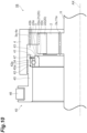
- the first modification example shown in FIG. 11 is a modification example of the cam member 31 in the clutch device 1A of the first embodiment.
- the cam outer ring portion 33 includes an inner member 51 having the raceway surface 33a, and an outer member 52 disposed outside the inner member 51 in the radial direction to come into contact with the claw members 22.
- the outer member 52 includes the protruding portion 33b on which the inclined surface 33c is formed, and comes into contact with the claw members 22 at the inclined surface 33c.
- the inner member 51 is a member constituting a bearing together with the cam inner ring portion 32, and the outer member 52 is a cam ring that lifts the claw members 22.
- a retaining ring 53 is provided opposite to the inner ring 2 of the inner member 51, and the inner member 51 is disposed between the outer member 52 and the retaining ring 53, so that the movement of the inner member 51 in the axial direction is restricted.
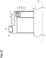
- a second modification example shown in FIG. 12 is a modification example of the cam member 41 in the clutch device 1B of the second embodiment.
- the cam inner ring portion 43 includes an outer member 61 having the raceway surface 43a, and an inner member 62 disposed inside the outer member 61 in the radial direction to come into contact with the claw members 22.
- the inner member 62 includes the protruding portion 43b on which the inclined surface 43c is formed, and comes into contact with the claw members 22 at the inclined surface 43c.
- the outer member 61 is a member constituting a bearing together with the cam outer ring portion 42, and the inner member 62 is a cam ring that pushes down the claw members 22.
- a retaining ring 63 is provided opposite to the outer ring 3 of the outer member 61, and the outer member 61 is disposed between the inner member 62 and the retaining ring 63, so that the movement of the outer member 61 in the axial direction is restricted.
Landscapes
- Engineering & Computer Science (AREA)
- General Engineering & Computer Science (AREA)
- Mechanical Engineering (AREA)
- Mechanical Operated Clutches (AREA)
- One-Way And Automatic Clutches, And Combinations Of Different Clutches (AREA)
Description
- One aspect of the present disclosure relates to a clutch device.
- For example, in a clutch device described in
Japanese Unexamined Patent Publication No. 2020-118250 - In the switchable ratchet type clutch device described above, it is necessary to provide both the cam member and the claw members on an inner ring side as in Japanese Unexamined Patent Publication No.
2020-118250 - An object of one aspect of the present disclosure is to provide a clutch device capable of increasing the degree of freedom in design while suppressing an increase in drag loss.
- According to one aspect of the present disclosure, there is provided a clutch device including: [1] "an inner ring; an outer ring; a ratchet engagement mechanism including a notch provided on one of an outer peripheral portion of the inner ring and an inner peripheral portion of the outer ring, and an engaging member that is provided on the other of the outer peripheral portion of the inner ring and the inner peripheral portion of the outer ring and that engages with the notch to restrict a rotation between the inner ring and the outer ring in one direction; and a switching mechanism that includes a cam member movable in an axial direction with respect to the inner ring and the outer ring, and that switches an engagement state of the ratchet engagement mechanism between a first state where the engaging member is engaged with the notch and a second state where the engaging member is not engaged with the notch, by causing the cam member to move in the axial direction and come into contact with the engaging member. When the engaging member is provided on the inner peripheral portion of the outer ring, the cam member includes a cam inner ring portion provided to rotate together with the inner ring, a cam outer ring portion disposed outside the cam inner ring portion in a radial direction, and a plurality of rolling elements disposed between the cam inner ring portion and the cam outer ring portion, and the cam member moves in the axial direction to cause the cam outer ring portion to come into contact with the engaging member so as to switch the first state and the second state. When the engaging member is provided on the outer peripheral portion of the inner ring, the cam member includes a cam outer ring portion provided to rotate together with the outer ring, a cam inner ring portion disposed inside the cam outer ring portion in the radial direction, and a plurality of rolling elements disposed between the cam inner ring portion and the cam outer ring portion, and the cam member moves in the axial direction to cause the cam inner ring portion to come into contact with the engaging member so as to switch the first state and the second state."
- In the clutch device, when the engaging member is provided on the inner peripheral portion of the outer ring, the cam member (cam inner ring portion) is provided to rotate together with the inner ring, and when the engaging member is provided on the outer peripheral portion of the inner ring, the cam member (cam outer ring portion) is provided to rotate together with the outer ring. Namely, one of the engaging member and the cam member is provided on an inner ring side, and the other is provided on an outer ring side. Accordingly, the degree of freedom in design can be increased. On the other hand, when such a configuration is adopted, as described above, wear may occur between the cam member and the engaging member due to a difference in rotation speed between the inner ring and the outer ring, so that drag loss can be increased. In this regard, in the clutch device, the cam member includes the cam inner ring portion, the cam outer ring portion, and the plurality of rolling elements, and has the function of a bearing. Accordingly, the occurrence of wear between the cam member and the engaging member can be suppressed, and an increase in drag loss can be suppressed. Therefore, according to the clutch device, it is possible to increase the degree of freedom in design while suppressing an increase in drag loss.
- In the clutch device according to one aspect of the present disclosure described in [1], [2] "the notch may be provided on the outer peripheral portion of the inner ring, and the engaging member may be provided on the inner peripheral portion of the outer ring." In this case, since the cam member (cam inner ring portion) is provided on the inner ring side, space saving in the radial direction can be achieved.
- In the clutch device according to one aspect of the present disclosure described in [1], [3] "the notch may be provided on the inner peripheral portion of the outer ring, and the engaging member may be provided on the outer peripheral portion of the inner ring." In this case, since the cam member (cam outer ring portion) is provided on the outer ring side, a space for disposing other components and the like can be secured inside the cam member in the radial direction.
- In the clutch device according to one aspect of the present disclosure described in any one of [1] to [3], [4] "when the engaging member is provided on the inner peripheral portion of the outer ring, the cam outer ring portion may consist of one member, and when the engaging member is provided on the outer peripheral portion of the inner ring, the cam inner ring portion may consist of one member." In this case, the number of components can be reduced, and cost reduction can be achieved. In addition, space saving in the axial direction can be achieved.
- According to one aspect of the present disclosure, it is possible to provide the clutch device capable of increasing the degree of freedom in design while suppressing an increase in drag loss.
-
-
FIG. 1 is a perspective view of a clutch device of a first embodiment. -
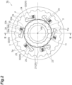
FIG. 2 is a front view of the clutch device of the first embodiment in a free state. -
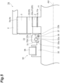
FIG. 3 is a cross-sectional view taken along line III-III ofFIG. 2 . -
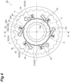
FIG. 4 is a front view of the clutch device of the first embodiment in a one-way state. -
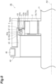
FIG. 5 is a cross-sectional view taken along line V-V ofFIG. 4 . -
FIG. 6 is a perspective view of a clutch device of a second embodiment. -
FIG. 7 is a front view of the clutch device of the second embodiment in the free state. -
FIG. 8 is a cross-sectional view taken along line VIII-VIII ofFIG. 7 . -
FIG. 9 is a front view of the clutch device of the second embodiment in the one-way state. -
FIG. 10 is a cross-sectional view taken along line X-X ofFIG. 9 . -
FIG. 11 is a cross-sectional view of a cam member of a first modification example. -
FIG. 12 is a cross-sectional view of a cam member of a second modification example. - Hereinafter, embodiments of the present disclosure will be described in detail with reference to the drawings. In the following description, the same reference signs are used for the same or equivalent elements, and duplicate descriptions will be omitted.
- As shown in
FIGS. 1 to 5 , aclutch device 1A of a first embodiment includes aninner ring 2 and anouter ring 3. Theouter ring 3 is disposed outside theinner ring 2 in a radial direction. Each of theinner ring 2 and theouter ring 3 is formed in an annular shape. Theinner ring 2 and theouter ring 3 are disposed coaxially with each other, have a common rotation axis AX, and are rotatable relative to each other. Hereinafter, theouter ring 3 may be described as rotating with respect to theinner ring 2; however, rotation between theinner ring 2 and theouter ring 3 is relative to each other. In addition, a direction parallel to the rotation axis AX will be described as an axial direction, a direction perpendicular to the rotation axis AX will be described as the radial direction, and a direction along a circumference having the rotation axis AX as the center when viewed in the axial direction will be described as a circumferential direction. - The
inner ring 2 is fitted to ashaft 11 at an inner peripheral portion of theinner ring 2, and rotates together with theshaft 11. In this example, aspline portion 2a is formed on the inner peripheral portion of theinner ring 2, and aspline portion 11a is formed on an outer peripheral portion of theshaft 11, and theinner ring 2 and theshaft 11 are coupled by fitting thespline portions spline portions - The
outer ring 3 is fitted to ahousing member 4 at an outer peripheral portion of theouter ring 3, and rotates together with thehousing member 4. In this example, aspline portion 3a is formed on the outer peripheral portion of theouter ring 3, and aspline portion 4a is formed on an inner peripheral portion of thehousing member 4, and theouter ring 3 and thehousing member 4 are coupled by fitting thespline portions spline portions - The
inner ring 2 and theouter ring 3 can be engaged with each other by aratchet engagement mechanism 20. Theratchet engagement mechanism 20 includes a plurality ofnotches 21 provided on an outer peripheral portion of theinner ring 2, and a plurality of claw members 22 (engaging members) provided on an inner peripheral portion of theouter ring 3. - A plurality of
tooth portions 23 protruding outward in the radial direction and extending in the axial direction are formed on the outer peripheral portion (outer peripheral surface) of theinner ring 2. The plurality oftooth portions 23 are provided over the entire circumference so as to be arranged at equal intervals along the circumferential direction. One notch 21 (groove) is formed by a space between thetooth portions 23 adjacent to each other in the circumferential direction. Therefore, the plurality ofnotches 21 are formed on the outer peripheral portion of theinner ring 2 so as to be arranged at equal intervals over the entire circumference in the circumferential direction. - Each of the
claw members 22 includes acolumnar portion 22b, and is supported by theouter ring 3 so as to be oscillatable about thecolumnar portion 22b in the radial direction (along a plane perpendicular to the axial direction). Specifically, theclaw members 22 are disposed in a plurality ofrespective recesses 24 formed on the inner peripheral portion (inner peripheral surface) of theouter ring 3, so that theclaw members 22 are oscillatable about thecolumnar portions 22b in the radial direction. Each of therecesses 24 is open on the inner peripheral surface of theouter ring 3. The plurality ofrecesses 24 are provided over the entire circumference so as to be arranged at equal intervals along the circumferential direction. - A biasing
member 25 is further disposed in each of therecesses 24. Namely, therecess 24 includes afirst portion 24a in which theclaw member 22 is disposed, and asecond portion 24b in which the biasingmember 25 is disposed. Thesecond portion 24b is connected to thefirst portion 24a. The biasingmember 25 is, for example, a coil spring, and biases anend portion 22a of theclaw member 22 inward (toward aninner ring 2 side) in the radial direction. Theend portion 22a is one end of theclaw member 22 in the circumferential direction, and functions as a claw portion that engages with thenotch 21 as will be described later. Theclaw member 22 is disposed to be inclined such that theend portion 22a can protrude from therecess 24. In each of therecesses 24, the biasingmember 25 is disposed in a compressed state between a bottom surface of thesecond portion 24b and theend portion 22a of theclaw member 22. - In the
clutch device 1A, the engagement state between theinner ring 2 and theouter ring 3 by theratchet engagement mechanism 20 can be switched by aswitching mechanism 30. Namely, theclutch device 1A is a switchable ratchet type clutch device (selectable clutch). Theswitching mechanism 30 switches the engagement state by theratchet engagement mechanism 20 between a one-way state (first state) (FIGS. 4 and5 ) and a free state (second state) (FIGS. 1 to 3 ). Note that hatching indicating a cross section is omitted inFIGS. 3 and5 . This point also applies toFIG. 8 andFIGS. 10 to 12 to be described later. - In the one-way state, when the
outer ring 3 rotates in one rotation direction (one direction) (clockwise direction inFIG. 4 ) with respect to theinner ring 2, theend portions 22a of theclaw members 22 engage (mesh) with thenotches 21, and the rotation of theouter ring 3 with respect to theinner ring 2 in the one rotation direction is locked (restricted). On the other hand, when theouter ring 3 rotates in the other rotation direction (opposite direction opposite to the one direction) (counterclockwise direction inFIG. 4 ) with respect to theinner ring 2 in the one-way state, theclaw members 22 do not engage with thenotches 21, and the rotation of theouter ring 3 with respect to theinner ring 2 in the other rotation direction is allowed (theouter ring 3 rotates freely). Namely, in the one-way state, torque is transmitted between theinner ring 2 and theouter ring 3 only when theouter ring 3 rotates in the one rotation direction with respect to theinner ring 2. In this example, torque is transmitted from thehousing member 4 to the inner ring 2 (shaft 11) via theouter ring 3 and theclaw members 22. - In the free state, regardless of whether the
outer ring 3 rotates with respect to theinner ring 2 in the one rotation direction (clockwise direction inFIG. 2 ) or in the other rotation direction (counterclockwise direction inFIG. 2 ), theclaw members 22 do not engage with thenotches 21, and the rotation of theouter ring 3 with respect to theinner ring 2 in both the rotation directions is allowed. Namely, in the free state, regardless of whether theouter ring 3 rotates with respect to theinner ring 2 in the one rotation direction or in the other rotation direction, torque is not transmitted between theinner ring 2 and theouter ring 3. - As shown in
FIGS. 3 and5 , theswitching mechanism 30 includes a cam member 31 (switching cam) that is movable in the axial direction with respect to theinner ring 2 and theouter ring 3, and switches the engagement state of theratchet engagement mechanism 20 between the one-way state and the free state by causing thecam member 31 to move in the axial direction and come into contact with theclaw members 22. Thecam member 31 is configured as a cam bearing having the function of a bearing, and includes a caminner ring portion 32, a camouter ring portion 33, and a plurality of rollingelements 34. In this example, the rollingelements 34 are balls. Each of the caminner ring portion 32 and the camouter ring portion 33 is formed in an annular shape. The caminner ring portion 32 and the camouter ring portion 33 are disposed coaxially with theinner ring 2 and theouter ring 3, and have the rotation axis AX common to theinner ring 2 and theouter ring 3. Each of the caminner ring portion 32 and the camouter ring portion 33 is composed of one member. - The cam
inner ring portion 32 has araceway surface 32a facing outward in the radial direction. Theraceway surface 32a is formed in a shape corresponding to the rollingelements 34. The caminner ring portion 32 is attached to theshaft 11 via asupport member 35, and rotates together with the inner ring 2 (in synchronization with the inner ring 2). Thesupport member 35 is an annular member that is attached to theshaft 11 so as to be movable in the axial direction, and is moved in the axial direction by the driving force of anactuator 36. The caminner ring portion 32 is fitted to anend portion 35a of thesupport member 35 at an inner peripheral portion of the caminner ring portion 32. Theend portion 35a is an end portion (end portion on theinner ring 2 side) of thesupport member 35 in the axial direction. In this example, a retainingring 37 is provided on theinner ring 2 side of the caminner ring portion 32, and the caminner ring portion 32 is disposed between thesupport member 35 and the retainingring 37, so that the movement of the caminner ring portion 32 in the axial direction is restricted. - The cam
outer ring portion 33 is disposed outside the caminner ring portion 32 in the radial direction. The camouter ring portion 33 has araceway surface 33a facing inward in the radial direction. Theraceway surface 33a is formed in a shape corresponding to the rollingelements 34. The camouter ring portion 33 includes a protrudingportion 33b protruding with respect to the caminner ring portion 32 in the axial direction (located on theinner ring 2 side). Aninclined surface 33c inclined with respect to the axial direction is formed over the entire circumference of an outer peripheral portion of the protrudingportion 33b. Theinclined surface 33c is formed over the entirety of the protrudingportion 33b in the axial direction. Theinclined surface 33c comes into contact with theclaw members 22 as will be described later. In such a manner, a length of the camouter ring portion 33 in the axial direction is longer than a length of the caminner ring portion 32 in the axial direction. In addition, a thickness of the camouter ring portion 33 in the radial direction is thicker than a thickness of the caminner ring portion 32 in the radial direction. Note that the length of the camouter ring portion 33 in the axial direction may be equal to or less than the length of the caminner ring portion 32 in the axial direction, and the thickness of the camouter ring portion 33 in the radial direction may be equal to or less than the thickness of the caminner ring portion 32 in the radial direction. - The plurality of rolling
elements 34 are disposed between theraceway surface 32a of the caminner ring portion 32 and theraceway surface 33a of the camouter ring portion 33. The plurality of rollingelements 34 are rollably held by a retainer (not shown), and are disposed side by side at predetermined intervals along the circumferential direction. - In the free state shown in
FIGS. 1 to 3 , the camouter ring portion 33 comes into contact with theend portions 22a of theclaw members 22 at an outer peripheral portion of the camouter ring portion 33. Accordingly, theend portions 22a are lifted (moved outward in the radial direction) to compress the biasingmembers 25, and theend portions 22a are located at positions where theend portions 22a do not engage with thenotches 21. As a result, as described above, regardless of whether theouter ring 3 rotates with respect to theinner ring 2 in the one rotation direction or in the other rotation direction, theclaw members 22 do not engage with thenotches 21, and the rotation of theouter ring 3 with respect to theinner ring 2 in both the rotation directions is allowed. In the free state, when there is a difference in rotation speed between theinner ring 2 and theouter ring 3, there also occurs a difference in rotation speed between the caminner ring portion 32 rotating in synchronization with theinner ring 2 and theclaw members 22 rotating in synchronization with theouter ring 3; however, the difference in rotation speed is absorbed by the rotation of the camouter ring portion 33 in contact with theclaw members 22 with respect to the caminner ring portion 32. - When the cam member 31 (cam inner ring portion 32) moves away from the
inner ring 2 and theouter ring 3 in the axial direction from the free state, the camouter ring portion 33 separates from theend portions 22a of theclaw members 22, so that the one-way state shown inFIGS. 4 and5 is reached. In the one-way state, the biasing force of the biasingmembers 25 locates theend portions 22a at positions where theend portions 22a engage with thenotches 21. As a result, as described above, when theouter ring 3 rotates with respect to theinner ring 2 in the one rotation direction, theend portions 22a engage with thenotches 21, and the rotation of theouter ring 3 with respect to theinner ring 2 in the one rotation direction is locked. When the cam member 31 (cam inner ring portion 32) moves toward theinner ring 2 and theouter ring 3 in the axial direction from the one-way state, and the camouter ring portion 33 comes into contact with theend portions 22a at the outer peripheral portion, the free state is reached. At this time, the camouter ring portion 33 first comes into contact with theend portions 22a at theinclined surface 33c, and then comes into contact with theend portions 22a at the outer peripheral portion. Accordingly, theend portions 22a of theclaw members 22 can be suitably moved outward in the radial direction by the camouter ring portion 33. - In a
clutch device 1B of a second embodiment shown inFIGS. 6 to 10 , thenotches 21 are provided on the inner peripheral portion of theouter ring 3, and theclaw members 22 are provided on the outer peripheral portion of theinner ring 2. Therefore, thetooth portions 23 constituting thenotches 21 are also provided on the inner peripheral portion of theouter ring 3, and therecesses 24 in which theclaw members 22 are disposed are also provided on the outer peripheral portion of theinner ring 2. The biasingmembers 25 bias theend portions 22a of theclaw members 22 outward (toward anouter ring 3 side) in the radial direction. - The
clutch device 1B includes acam member 41 instead of thecam member 31. Thecam member 41 is configured as a cam bearing having the function of a bearing, and includes a camouter ring portion 42, a caminner ring portion 43, and a plurality of the rollingelements 34. Each of the camouter ring portion 42 and the caminner ring portion 43 is formed in an annular shape. The camouter ring portion 42 and the caminner ring portion 43 are disposed coaxially with theinner ring 2 and theouter ring 3, and have the rotation axis AX common to theinner ring 2 and theouter ring 3. Each of the camouter ring portion 42 and the caminner ring portion 43 is composed of one member. - The cam
outer ring portion 42 has araceway surface 42a facing inward in the radial direction. Theraceway surface 42a is formed in a shape corresponding to the rollingelements 34. The camouter ring portion 42 is attached to thehousing member 4 via asupport member 45, and rotates together with the outer ring 3 (in synchronization with the outer ring 3). Thesupport member 45 is an annular member that is attached to thehousing member 4 so as to be movable in the axial direction, and is moved in the axial direction by the driving force of anactuator 46. The camouter ring portion 42 is fitted to anend portion 45a of thesupport member 45 at an outer peripheral portion of the camouter ring portion 42. Theend portion 45a is an end portion (end portion on theouter ring 3 side) of thesupport member 45 in the axial direction. In this example, a retainingring 47 is provided on theouter ring 3 side of the camouter ring portion 42, and the camouter ring portion 42 is disposed between thesupport member 45 and the retainingring 47, so that the movement of the camouter ring portion 42 in the axial direction is restricted. - The cam
inner ring portion 43 is disposed inside the camouter ring portion 42 in the radial direction. The caminner ring portion 43 has araceway surface 43a facing outward in the radial direction. Theraceway surface 43a is formed in a shape corresponding to the rollingelements 34. The caminner ring portion 43 includes a protrudingportion 43b protruding with respect to the camouter ring portion 42 in the axial direction (located on theouter ring 3 side). Aninclined surface 43c inclined with respect to the axial direction is formed over the entire circumference of an inner peripheral portion of the protrudingportion 43b. Theinclined surface 43c is formed over the entirety of the protrudingportion 43b in the axial direction. Theinclined surface 43c comes into contact with theclaw members 22 as will be described later. In such a manner, a length of the caminner ring portion 43 in the axial direction is longer than a length of the camouter ring portion 42 in the axial direction. In addition, a thickness of the caminner ring portion 43 in the radial direction is thicker than a thickness of the camouter ring portion 42 in the radial direction. Note that the length of the caminner ring portion 43 in the axial direction may be equal to or less than the length of the camouter ring portion 42 in the axial direction, and the thickness of the caminner ring portion 43 in the radial direction may be equal to or less than the thickness of the camouter ring portion 42 in the radial direction. - In the free state shown in
FIGS. 7 and8 , the caminner ring portion 43 comes into contact with theend portions 22a of theclaw members 22 at an inner peripheral portion of the caminner ring portion 43. Accordingly, theend portions 22a are pushed down (moved inward in the radial direction) to compress the biasingmembers 25, and theend portions 22a are located at positions where theend portions 22a do not engage with thenotches 21. As a result, regardless of whether theouter ring 3 rotates with respect to theinner ring 2 in the one rotation direction or in the other rotation direction, theclaw members 22 do not engage with thenotches 21, and the rotation of theouter ring 3 with respect to theinner ring 2 in both the rotation directions is allowed. In the free state, when there is a difference in rotation speed between theinner ring 2 and theouter ring 3, there also occurs a difference in rotation speed between the camouter ring portion 42 rotating in synchronization with theouter ring 3 and theclaw members 22 rotating in synchronization with theinner ring 2; however, the difference in rotation speed is absorbed by the rotation of the caminner ring portion 43 in contact with theclaw members 22 with respect to the camouter ring portion 42. - When the cam member 41 (cam outer ring portion 42) moves away from the
inner ring 2 and theouter ring 3 in the axial direction from the free state, the caminner ring portion 43 separates from theend portions 22a of theclaw members 22, so that the one-way state shown inFIGS. 9 and10 is reached. In the one-way state, the biasing force of the biasingmembers 25 locates theend portions 22a at positions where theend portions 22a engage with thenotches 21. As a result, when theouter ring 3 rotates with respect to theinner ring 2 in the one rotation direction, theend portions 22a engage with thenotches 21, and the rotation of theouter ring 3 with respect to theinner ring 2 in the one rotation direction is locked. When the cam member 41 (cam outer ring portion 42) moves toward theinner ring 2 and theouter ring 3 in the axial direction from the one-way state, and the caminner ring portion 43 comes into contact with theend portions 22a at the inner peripheral portion, the free state is reached. At this time, the caminner ring portion 43 first comes into contact with theend portions 22a at theinclined surface 43c, and then comes into contact with theend portions 22a at the inner peripheral portion. Accordingly, theend portions 22a of theclaw members 22 can be suitably moved inward in the radial direction by the caminner ring portion 43. - In the
clutch devices clutch device 1A), the cam member 31 (cam inner ring portion 32) is provided to rotate together with theinner ring 2, and when theclaw members 22 are provided on the outer peripheral portion of the inner ring 2 (clutch device 1B), the cam member 41 (cam outer ring portion 42) is provided to rotate together with theouter ring 3. Namely, one of theclaw members 22 and thecam members inner ring 2 side, and the other is provided on theouter ring 3 side. Accordingly, the degree of freedom in design can be increased. On the other hand, when such a configuration is adopted, wear may occur between thecam members claw members 22 due to a difference in rotation speed between theinner ring 2 and theouter ring 3, so that drag loss can be increased. In this regard, in theclutch devices elements 34, and has the function of a bearing. Accordingly, the occurrence of wear between thecam members claw members 22 can be suppressed, and an increase in drag loss can be suppressed. Therefore, according to theclutch devices - In the
clutch device 1A, thenotches 21 are provided on the outer peripheral portion of theinner ring 2, and theclaw members 22 are provided on the inner peripheral portion of theouter ring 3. In this case, since the cam member 31 (cam inner ring portion 32) is provided on theinner ring 2 side, space saving in the radial direction can be achieved. For example, unlike theclutch device 1A, in a case where the cam member is composed of an integral member not having the function of a bearing, when theclaw members 22 are provided on the inner peripheral portion of theouter ring 3, as described above, in order to avoid the occurrence of wear between the cam member and theclaw members 22, both the cam member and theclaw members 22 need to be provided on theouter ring 3 side. In this case, for example, the cam member is spline-coupled with an outer peripheral portion of thehousing member 4, so that the size is increased in the radial direction. In contrast, in theclutch device 1A, since thecam member 31 having the function of a bearing is provided on theinner ring 2 side, space saving in the radial direction can be achieved. In addition, since a spline for coupling with the cam member does not need to be formed on thehousing member 4, cost reduction can be achieved. - In the
clutch device 1B, thenotches 21 are provided on the inner peripheral portion of theouter ring 3, and theclaw members 22 are provided on the outer peripheral portion of theinner ring 2. In this case, since the cam member 41 (cam outer ring portion 42) is provided on theouter ring 3 side, a space for disposing other components and the like can be secured inside thecam member 41 in the radial direction. - In the
clutch device 1A, the camouter ring portion 33 is composed of one member, and in theclutch device 1B, the caminner ring portion 43 is composed of one member. In this case, compared to when the camouter ring portion 33 or the caminner ring portion 43 is composed of a plurality of members, the number of components can be reduced, and cost reduction can be achieved. In addition, space saving in the axial direction can be achieved. For example, when a comparative example is a case where the camouter ring portion 33 includes an inner member having theraceway surface 33a and an outer member that comes into contact with the claw members 22 (for example, a first modification example to be described later), in theclutch device 1A, the number of components can be reduced compared to the comparative example. In addition, in the comparative example, a retaining ring for fixing the outer member to the inner member is required; however, when the camouter ring portion 33 is composed of one member, such a retaining ring can be omitted. In addition, in the comparative example, the outer member protrudes with respect to the inner member in the axial direction, so that the size is increased, which is a risk; however, when the camouter ring portion 33 is composed of one member, such a risk does not occur, and space saving in the axial direction can be achieved. - The present disclosure is not limited to the above embodiments. For example, the material and shape of each configuration are not limited to the material and shape described above, and various materials and shapes can be adopted. The rolling
elements 34 are not limited to balls, and may be rollers or the like. - The first modification example shown in
FIG. 11 is a modification example of thecam member 31 in theclutch device 1A of the first embodiment. In the first modification example, the camouter ring portion 33 includes aninner member 51 having theraceway surface 33a, and anouter member 52 disposed outside theinner member 51 in the radial direction to come into contact with theclaw members 22. Theouter member 52 includes the protrudingportion 33b on which theinclined surface 33c is formed, and comes into contact with theclaw members 22 at theinclined surface 33c. Theinner member 51 is a member constituting a bearing together with the caminner ring portion 32, and theouter member 52 is a cam ring that lifts theclaw members 22. In this example, a retainingring 53 is provided opposite to theinner ring 2 of theinner member 51, and theinner member 51 is disposed between theouter member 52 and the retainingring 53, so that the movement of theinner member 51 in the axial direction is restricted. Even in the case of using thecam member 31 of the first modification example, similarly to the first embodiment, it is possible to increase the degree of freedom in design while suppressing an increase in drag loss. - A second modification example shown in
FIG. 12 is a modification example of thecam member 41 in theclutch device 1B of the second embodiment. In the second modification example, the caminner ring portion 43 includes anouter member 61 having theraceway surface 43a, and aninner member 62 disposed inside theouter member 61 in the radial direction to come into contact with theclaw members 22. Theinner member 62 includes the protrudingportion 43b on which theinclined surface 43c is formed, and comes into contact with theclaw members 22 at theinclined surface 43c. Theouter member 61 is a member constituting a bearing together with the camouter ring portion 42, and theinner member 62 is a cam ring that pushes down theclaw members 22. In this example, a retainingring 63 is provided opposite to theouter ring 3 of theouter member 61, and theouter member 61 is disposed between theinner member 62 and the retainingring 63, so that the movement of theouter member 61 in the axial direction is restricted. Even in the case of using thecam member 41 of the second modification example, similarly to the second embodiment, it is possible to increase the degree of freedom in design while suppressing an increase in drag loss.
Claims (4)
- A clutch device (1A, 1B) comprising:an inner ring (2);an outer ring (3);a ratchet engagement mechanism (20) including a notch (21) provided on one of an outer peripheral portion of the inner ring (2) and an inner peripheral portion of the outer ring (3), and an engaging member (22) that is provided on the other of the outer peripheral portion of the inner ring (2) and the inner peripheral portion of the outer ring (3) and that engages with the notch (21) to restrict a rotation between the inner ring (2) and the outer ring (3) in one direction; anda switching mechanism (30) that includes a cam member (31, 41) movable in an axial direction with respect to the inner ring (2) and the outer ring (3), and that switches an engagement state of the ratchet engagement mechanism (20) between a first state where the engaging member (22) is engaged with the notch (21) and a second state where the engaging member (22) is not engaged with the notch (21), by causing the cam member (31, 41) to move in the axial direction and come into contact with the engaging member (22),characterized in thatwhen the engaging member (22) is provided on the inner peripheral portion of the outer ring (3), the cam member (31, 41) includes a cam inner ring portion (32, 43) provided to rotate together with the inner ring (2), a cam outer ring portion (33, 42) disposed outside the cam inner ring portion (32, 43) in a radial direction, and a plurality of rolling elements (34) disposed between the cam inner ring portion (32, 43) and the cam outer ring portion (33, 42), and the cam member (31, 41) moves in the axial direction to cause the cam outer ring portion (33, 42) to come into contact with the engaging member (22) so as to switch the first state and the second state, andwhen the engaging member (22) is provided on the outer peripheral portion of the inner ring (2), the cam member (31, 41) includes a cam outer ring portion (33, 42) provided to rotate together with the outer ring (3), a cam inner ring portion (32, 43) disposed inside the cam outer ring portion (33, 42) in the radial direction, and a plurality of rolling elements (34) disposed between the cam inner ring portion and the cam outer ring portion (33, 42), and the cam member (31, 41) moves in the axial direction to cause the cam inner ring portion (32, 43) to come into contact with the engaging member (22) so as to switch the first state and the second state.
- The clutch device (1A, 1B) according to claim 1,
wherein the notch (21) is provided on the outer peripheral portion of the inner ring (2), and the engaging member (22) is provided on the inner peripheral portion of the outer ring (3). - The clutch device (1A, 1B) according to claim 1,
wherein the notch (21) is provided on the inner peripheral portion of the outer ring (3), and the engaging member (22) is provided on the outer peripheral portion of the inner ring (2). - The clutch device (1A, 1B) according to any one of claims 1 to 3,wherein when the engaging member (22) is provided on the inner peripheral portion of the outer ring (3), the cam outer ring portion (33, 42) consists of one member, andwhen the engaging member (22) is provided on the outer peripheral portion of the inner ring (2), the cam inner ring portion (32, 43) consists of one member.
Applications Claiming Priority (1)
| Application Number | Priority Date | Filing Date | Title |
|---|---|---|---|
| JP2022187958A JP7850060B2 (en) | 2022-11-25 | 2022-11-25 | Clutch device |
Publications (2)
| Publication Number | Publication Date |
|---|---|
| EP4375529A1 EP4375529A1 (en) | 2024-05-29 |
| EP4375529B1 true EP4375529B1 (en) | 2025-04-23 |
Family
ID=88647547
Family Applications (1)
| Application Number | Title | Priority Date | Filing Date |
|---|---|---|---|
| EP23206874.2A Active EP4375529B1 (en) | 2022-11-25 | 2023-10-31 | Clutch device |
Country Status (4)
| Country | Link |
|---|---|
| US (1) | US12222011B2 (en) |
| EP (1) | EP4375529B1 (en) |
| JP (1) | JP7850060B2 (en) |
| CN (1) | CN118088593A (en) |
Citations (1)
| Publication number | Priority date | Publication date | Assignee | Title |
|---|---|---|---|---|
| US20190264760A1 (en) * | 2016-11-10 | 2019-08-29 | Borgwarner Inc. | Sector clutch |
Family Cites Families (10)
| Publication number | Priority date | Publication date | Assignee | Title |
|---|---|---|---|---|
| JPS50106055A (en) | 1974-01-26 | 1975-08-21 | ||
| JP4361399B2 (en) | 2004-03-05 | 2009-11-11 | 株式会社ケイセブン | clutch |
| US7500548B2 (en) * | 2004-07-27 | 2009-03-10 | Ford Global Technologies, Llc | Dual-mode one-way torque transmitting device |
| EP2951456B1 (en) | 2013-01-30 | 2017-11-08 | BorgWarner Inc. | Multi-mode clutch module |
| DE112016001151T5 (en) * | 2015-04-14 | 2017-11-23 | Borgwarner Inc. | MULTIMODAL CLUTCH SYSTEM WITH CAMSHIELD PROFILES |
| US10151359B2 (en) | 2016-05-24 | 2018-12-11 | Borgwarner Inc. | Rotating multi-mode clutch module with stationary actuator |
| US10036433B2 (en) * | 2016-06-14 | 2018-07-31 | Ford Global Technologies, Llc | Clutch for continuously variable transmission |
| WO2020150833A1 (en) * | 2019-01-25 | 2020-07-30 | Magna Powertrain, Inc. | Rotating electrically-controlled one-way clutch (eowc) with ball cam actuation mechanism |
| JP7123500B2 (en) | 2019-01-25 | 2022-08-23 | Nskワーナー株式会社 | clutch device |
| CN111120542A (en) * | 2020-01-15 | 2020-05-08 | 无锡明恒混合动力技术有限公司 | Mode-selectable clutch |
-
2022
- 2022-11-25 JP JP2022187958A patent/JP7850060B2/en active Active
-
2023
- 2023-10-31 EP EP23206874.2A patent/EP4375529B1/en active Active
- 2023-10-31 US US18/498,871 patent/US12222011B2/en active Active
- 2023-11-21 CN CN202311553250.3A patent/CN118088593A/en active Pending
Patent Citations (1)
| Publication number | Priority date | Publication date | Assignee | Title |
|---|---|---|---|---|
| US20190264760A1 (en) * | 2016-11-10 | 2019-08-29 | Borgwarner Inc. | Sector clutch |
Also Published As
| Publication number | Publication date |
|---|---|
| CN118088593A (en) | 2024-05-28 |
| US12222011B2 (en) | 2025-02-11 |
| EP4375529A1 (en) | 2024-05-29 |
| US20240175471A1 (en) | 2024-05-30 |
| JP2024076448A (en) | 2024-06-06 |
| JP7850060B2 (en) | 2026-04-22 |
Similar Documents
| Publication | Publication Date | Title |
|---|---|---|
| KR102737932B1 (en) | Cam clutch | |
| US8596437B2 (en) | Synchronizing device for manual transmission | |
| US11761495B2 (en) | Cam clutch | |
| JP7123500B2 (en) | clutch device | |
| EP3037690B1 (en) | One-way clutch | |
| JP2022047794A (en) | Ratchet type clutch | |
| EP4375529A1 (en) | Clutch device | |
| US5758755A (en) | Sprag type one-way clutch | |
| JP2019078308A (en) | One-way clutch | |
| JP7703286B2 (en) | Clutch device | |
| US11846329B2 (en) | Cam clutch | |
| JP7692669B2 (en) | Ratchet Type Clutch | |
| EP4339477B1 (en) | One-way clutch | |
| US12398765B2 (en) | Positive clutch | |
| CN111801508B (en) | One-way clutch | |
| JP7192466B2 (en) | power transmission device | |
| EP4382761B1 (en) | Clutch device | |
| US20250305545A1 (en) | Cam clutch | |
| JP7573944B2 (en) | Ratchet Type Clutch | |
| US12366269B2 (en) | Cam clutch | |
| CN117703958A (en) | One-way clutch | |
| US12253122B2 (en) | Selectable clutch | |
| WO2017208843A1 (en) | Reverse input preventing clutch | |
| JP2025042324A (en) | Rotation transmission device | |
| JP2024086270A (en) | Cam clutch unit |
Legal Events
| Date | Code | Title | Description |
|---|---|---|---|
| PUAI | Public reference made under article 153(3) epc to a published international application that has entered the european phase |
Free format text: ORIGINAL CODE: 0009012 |
|
| STAA | Information on the status of an ep patent application or granted ep patent |
Free format text: STATUS: THE APPLICATION HAS BEEN PUBLISHED |
|
| AK | Designated contracting states |
Kind code of ref document: A1 Designated state(s): AL AT BE BG CH CY CZ DE DK EE ES FI FR GB GR HR HU IE IS IT LI LT LU LV MC ME MK MT NL NO PL PT RO RS SE SI SK SM TR |
|
| STAA | Information on the status of an ep patent application or granted ep patent |
Free format text: STATUS: REQUEST FOR EXAMINATION WAS MADE |
|
| 17P | Request for examination filed |
Effective date: 20240702 |
|
| RBV | Designated contracting states (corrected) |
Designated state(s): AL AT BE BG CH CY CZ DE DK EE ES FI FR GB GR HR HU IE IS IT LI LT LU LV MC ME MK MT NL NO PL PT RO RS SE SI SK SM TR |
|
| GRAP | Despatch of communication of intention to grant a patent |
Free format text: ORIGINAL CODE: EPIDOSNIGR1 |
|
| STAA | Information on the status of an ep patent application or granted ep patent |
Free format text: STATUS: GRANT OF PATENT IS INTENDED |
|
| INTG | Intention to grant announced |
Effective date: 20241212 |
|
| GRAS | Grant fee paid |
Free format text: ORIGINAL CODE: EPIDOSNIGR3 |
|
| GRAA | (expected) grant |
Free format text: ORIGINAL CODE: 0009210 |
|
| STAA | Information on the status of an ep patent application or granted ep patent |
Free format text: STATUS: THE PATENT HAS BEEN GRANTED |
|
| AK | Designated contracting states |
Kind code of ref document: B1 Designated state(s): AL AT BE BG CH CY CZ DE DK EE ES FI FR GB GR HR HU IE IS IT LI LT LU LV MC ME MK MT NL NO PL PT RO RS SE SI SK SM TR |
|
| REG | Reference to a national code |
Ref country code: GB Ref legal event code: FG4D |
|
| REG | Reference to a national code |
Ref country code: CH Ref legal event code: EP |
|
| REG | Reference to a national code |
Ref country code: DE Ref legal event code: R096 Ref document number: 602023003077 Country of ref document: DE |
|
| REG | Reference to a national code |
Ref country code: IE Ref legal event code: FG4D |
|
| REG | Reference to a national code |
Ref country code: NL Ref legal event code: MP Effective date: 20250423 |
|
| PG25 | Lapsed in a contracting state [announced via postgrant information from national office to epo] |
Ref country code: NL Free format text: LAPSE BECAUSE OF FAILURE TO SUBMIT A TRANSLATION OF THE DESCRIPTION OR TO PAY THE FEE WITHIN THE PRESCRIBED TIME-LIMIT Effective date: 20250423 |
|
| REG | Reference to a national code |
Ref country code: AT Ref legal event code: MK05 Ref document number: 1788005 Country of ref document: AT Kind code of ref document: T Effective date: 20250423 |
|
| PG25 | Lapsed in a contracting state [announced via postgrant information from national office to epo] |
Ref country code: FI Free format text: LAPSE BECAUSE OF FAILURE TO SUBMIT A TRANSLATION OF THE DESCRIPTION OR TO PAY THE FEE WITHIN THE PRESCRIBED TIME-LIMIT Effective date: 20250423 Ref country code: PT Free format text: LAPSE BECAUSE OF FAILURE TO SUBMIT A TRANSLATION OF THE DESCRIPTION OR TO PAY THE FEE WITHIN THE PRESCRIBED TIME-LIMIT Effective date: 20250825 Ref country code: ES Free format text: LAPSE BECAUSE OF FAILURE TO SUBMIT A TRANSLATION OF THE DESCRIPTION OR TO PAY THE FEE WITHIN THE PRESCRIBED TIME-LIMIT Effective date: 20250423 |
|
| REG | Reference to a national code |
Ref country code: LT Ref legal event code: MG9D |
|
| PG25 | Lapsed in a contracting state [announced via postgrant information from national office to epo] |
Ref country code: NO Free format text: LAPSE BECAUSE OF FAILURE TO SUBMIT A TRANSLATION OF THE DESCRIPTION OR TO PAY THE FEE WITHIN THE PRESCRIBED TIME-LIMIT Effective date: 20250723 Ref country code: GR Free format text: LAPSE BECAUSE OF FAILURE TO SUBMIT A TRANSLATION OF THE DESCRIPTION OR TO PAY THE FEE WITHIN THE PRESCRIBED TIME-LIMIT Effective date: 20250724 |
|
| PG25 | Lapsed in a contracting state [announced via postgrant information from national office to epo] |
Ref country code: PL Free format text: LAPSE BECAUSE OF FAILURE TO SUBMIT A TRANSLATION OF THE DESCRIPTION OR TO PAY THE FEE WITHIN THE PRESCRIBED TIME-LIMIT Effective date: 20250423 |
|
| PG25 | Lapsed in a contracting state [announced via postgrant information from national office to epo] |
Ref country code: BG Free format text: LAPSE BECAUSE OF FAILURE TO SUBMIT A TRANSLATION OF THE DESCRIPTION OR TO PAY THE FEE WITHIN THE PRESCRIBED TIME-LIMIT Effective date: 20250423 |
|
| PG25 | Lapsed in a contracting state [announced via postgrant information from national office to epo] |
Ref country code: HR Free format text: LAPSE BECAUSE OF FAILURE TO SUBMIT A TRANSLATION OF THE DESCRIPTION OR TO PAY THE FEE WITHIN THE PRESCRIBED TIME-LIMIT Effective date: 20250423 |
|
| PG25 | Lapsed in a contracting state [announced via postgrant information from national office to epo] |
Ref country code: AT Free format text: LAPSE BECAUSE OF FAILURE TO SUBMIT A TRANSLATION OF THE DESCRIPTION OR TO PAY THE FEE WITHIN THE PRESCRIBED TIME-LIMIT Effective date: 20250423 |
|
| PG25 | Lapsed in a contracting state [announced via postgrant information from national office to epo] |
Ref country code: RS Free format text: LAPSE BECAUSE OF FAILURE TO SUBMIT A TRANSLATION OF THE DESCRIPTION OR TO PAY THE FEE WITHIN THE PRESCRIBED TIME-LIMIT Effective date: 20250723 |
|
| PG25 | Lapsed in a contracting state [announced via postgrant information from national office to epo] |
Ref country code: IS Free format text: LAPSE BECAUSE OF FAILURE TO SUBMIT A TRANSLATION OF THE DESCRIPTION OR TO PAY THE FEE WITHIN THE PRESCRIBED TIME-LIMIT Effective date: 20250823 |
|
| PG25 | Lapsed in a contracting state [announced via postgrant information from national office to epo] |
Ref country code: LV Free format text: LAPSE BECAUSE OF FAILURE TO SUBMIT A TRANSLATION OF THE DESCRIPTION OR TO PAY THE FEE WITHIN THE PRESCRIBED TIME-LIMIT Effective date: 20250423 |
|
| PG25 | Lapsed in a contracting state [announced via postgrant information from national office to epo] |
Ref country code: SM Free format text: LAPSE BECAUSE OF FAILURE TO SUBMIT A TRANSLATION OF THE DESCRIPTION OR TO PAY THE FEE WITHIN THE PRESCRIBED TIME-LIMIT Effective date: 20250423 Ref country code: DK Free format text: LAPSE BECAUSE OF FAILURE TO SUBMIT A TRANSLATION OF THE DESCRIPTION OR TO PAY THE FEE WITHIN THE PRESCRIBED TIME-LIMIT Effective date: 20250423 |
|
| PGFP | Annual fee paid to national office [announced via postgrant information from national office to epo] |
Ref country code: IT Payment date: 20251031 Year of fee payment: 3 |
|
| PG25 | Lapsed in a contracting state [announced via postgrant information from national office to epo] |
Ref country code: CZ Free format text: LAPSE BECAUSE OF FAILURE TO SUBMIT A TRANSLATION OF THE DESCRIPTION OR TO PAY THE FEE WITHIN THE PRESCRIBED TIME-LIMIT Effective date: 20250423 |
|
| PG25 | Lapsed in a contracting state [announced via postgrant information from national office to epo] |
Ref country code: EE Free format text: LAPSE BECAUSE OF FAILURE TO SUBMIT A TRANSLATION OF THE DESCRIPTION OR TO PAY THE FEE WITHIN THE PRESCRIBED TIME-LIMIT Effective date: 20250423 |
|
| REG | Reference to a national code |
Ref country code: DE Ref legal event code: R097 Ref document number: 602023003077 Country of ref document: DE |
|
| PG25 | Lapsed in a contracting state [announced via postgrant information from national office to epo] |
Ref country code: SK Free format text: LAPSE BECAUSE OF FAILURE TO SUBMIT A TRANSLATION OF THE DESCRIPTION OR TO PAY THE FEE WITHIN THE PRESCRIBED TIME-LIMIT Effective date: 20250423 |
|
| PLBE | No opposition filed within time limit |
Free format text: ORIGINAL CODE: 0009261 |
|
| STAA | Information on the status of an ep patent application or granted ep patent |
Free format text: STATUS: NO OPPOSITION FILED WITHIN TIME LIMIT |
|
| REG | Reference to a national code |
Ref country code: CH Ref legal event code: L10 Free format text: ST27 STATUS EVENT CODE: U-0-0-L10-L00 (AS PROVIDED BY THE NATIONAL OFFICE) Effective date: 20260304 |
|
| PG25 | Lapsed in a contracting state [announced via postgrant information from national office to epo] |
Ref country code: RO Free format text: LAPSE BECAUSE OF FAILURE TO SUBMIT A TRANSLATION OF THE DESCRIPTION OR TO PAY THE FEE WITHIN THE PRESCRIBED TIME-LIMIT Effective date: 20250423 |
|
| 26N | No opposition filed |
Effective date: 20260126 |
|
| PGFP | Annual fee paid to national office [announced via postgrant information from national office to epo] |
Ref country code: DE Payment date: 20260129 Year of fee payment: 3 |
|
| PGFP | Annual fee paid to national office [announced via postgrant information from national office to epo] |
Ref country code: FR Payment date: 20260128 Year of fee payment: 3 |