EP4375500A1 - Hydraulic device, hydraulic motor and construction machine - Google Patents
Hydraulic device, hydraulic motor and construction machine Download PDFInfo
- Publication number
- EP4375500A1 EP4375500A1 EP23206055.8A EP23206055A EP4375500A1 EP 4375500 A1 EP4375500 A1 EP 4375500A1 EP 23206055 A EP23206055 A EP 23206055A EP 4375500 A1 EP4375500 A1 EP 4375500A1
- Authority
- EP
- European Patent Office
- Prior art keywords
- rotating body
- block
- oscillatory
- oscillatory rotating
- rotation
- Prior art date
- Legal status (The legal status is an assumption and is not a legal conclusion. Google has not performed a legal analysis and makes no representation as to the accuracy of the status listed.)
- Pending
Links
Images







Classifications
-
- F—MECHANICAL ENGINEERING; LIGHTING; HEATING; WEAPONS; BLASTING
- F15—FLUID-PRESSURE ACTUATORS; HYDRAULICS OR PNEUMATICS IN GENERAL
- F15B—SYSTEMS ACTING BY MEANS OF FLUIDS IN GENERAL; FLUID-PRESSURE ACTUATORS, e.g. SERVOMOTORS; DETAILS OF FLUID-PRESSURE SYSTEMS, NOT OTHERWISE PROVIDED FOR
- F15B11/00—Servomotor systems without provision for follow-up action; Circuits therefor
- F15B11/16—Servomotor systems without provision for follow-up action; Circuits therefor with two or more servomotors
-
- F—MECHANICAL ENGINEERING; LIGHTING; HEATING; WEAPONS; BLASTING
- F03—MACHINES OR ENGINES FOR LIQUIDS; WIND, SPRING, OR WEIGHT MOTORS; PRODUCING MECHANICAL POWER OR A REACTIVE PROPULSIVE THRUST, NOT OTHERWISE PROVIDED FOR
- F03C—POSITIVE-DISPLACEMENT ENGINES DRIVEN BY LIQUIDS
- F03C2/00—Rotary-piston engines
- F03C2/08—Rotary-piston engines of intermeshing-engagement type, i.e. with engagement of co- operating members similar to that of toothed gearing
-
- E—FIXED CONSTRUCTIONS
- E02—HYDRAULIC ENGINEERING; FOUNDATIONS; SOIL SHIFTING
- E02F—DREDGING; SOIL-SHIFTING
- E02F9/00—Component parts of dredgers or soil-shifting machines, not restricted to one of the kinds covered by groups E02F3/00 - E02F7/00
- E02F9/08—Superstructures; Supports for superstructures
- E02F9/10—Supports for movable superstructures mounted on travelling or walking gears or on other superstructures
- E02F9/12—Slewing or traversing gears
- E02F9/121—Turntables, i.e. structure rotatable about 360°
- E02F9/128—Braking systems
-
- F—MECHANICAL ENGINEERING; LIGHTING; HEATING; WEAPONS; BLASTING
- F03—MACHINES OR ENGINES FOR LIQUIDS; WIND, SPRING, OR WEIGHT MOTORS; PRODUCING MECHANICAL POWER OR A REACTIVE PROPULSIVE THRUST, NOT OTHERWISE PROVIDED FOR
- F03C—POSITIVE-DISPLACEMENT ENGINES DRIVEN BY LIQUIDS
- F03C4/00—Oscillating-piston engines
-
- E—FIXED CONSTRUCTIONS
- E02—HYDRAULIC ENGINEERING; FOUNDATIONS; SOIL SHIFTING
- E02F—DREDGING; SOIL-SHIFTING
- E02F9/00—Component parts of dredgers or soil-shifting machines, not restricted to one of the kinds covered by groups E02F3/00 - E02F7/00
- E02F9/20—Drives; Control devices
- E02F9/2058—Electric or electro-mechanical or mechanical control devices of vehicle sub-units
- E02F9/2083—Control of vehicle braking systems
-
- E—FIXED CONSTRUCTIONS
- E02—HYDRAULIC ENGINEERING; FOUNDATIONS; SOIL SHIFTING
- E02F—DREDGING; SOIL-SHIFTING
- E02F9/00—Component parts of dredgers or soil-shifting machines, not restricted to one of the kinds covered by groups E02F3/00 - E02F7/00
- E02F9/20—Drives; Control devices
- E02F9/22—Hydraulic or pneumatic drives
- E02F9/2246—Control of prime movers, e.g. depending on the hydraulic load of work tools
-
- E—FIXED CONSTRUCTIONS
- E02—HYDRAULIC ENGINEERING; FOUNDATIONS; SOIL SHIFTING
- E02F—DREDGING; SOIL-SHIFTING
- E02F9/00—Component parts of dredgers or soil-shifting machines, not restricted to one of the kinds covered by groups E02F3/00 - E02F7/00
- E02F9/20—Drives; Control devices
- E02F9/22—Hydraulic or pneumatic drives
- E02F9/2264—Arrangements or adaptations of elements for hydraulic drives
-
- F—MECHANICAL ENGINEERING; LIGHTING; HEATING; WEAPONS; BLASTING
- F04—POSITIVE - DISPLACEMENT MACHINES FOR LIQUIDS; PUMPS FOR LIQUIDS OR ELASTIC FLUIDS
- F04C—ROTARY-PISTON, OR OSCILLATING-PISTON, POSITIVE-DISPLACEMENT MACHINES FOR LIQUIDS; ROTARY-PISTON, OR OSCILLATING-PISTON, POSITIVE-DISPLACEMENT PUMPS
- F04C15/00—Component parts, details or accessories of machines, pumps or pumping installations, not provided for in groups F04C2/00 - F04C14/00
- F04C15/0057—Driving elements, brakes, couplings, transmission specially adapted for machines or pumps
- F04C15/0084—Brakes, braking assemblies
-
- F—MECHANICAL ENGINEERING; LIGHTING; HEATING; WEAPONS; BLASTING
- F04—POSITIVE - DISPLACEMENT MACHINES FOR LIQUIDS; PUMPS FOR LIQUIDS OR ELASTIC FLUIDS
- F04C—ROTARY-PISTON, OR OSCILLATING-PISTON, POSITIVE-DISPLACEMENT MACHINES FOR LIQUIDS; ROTARY-PISTON, OR OSCILLATING-PISTON, POSITIVE-DISPLACEMENT PUMPS
- F04C2/00—Rotary-piston machines or pumps
- F04C2/08—Rotary-piston machines or pumps of intermeshing-engagement type, i.e. with engagement of co-operating members similar to that of toothed gearing
- F04C2/10—Rotary-piston machines or pumps of intermeshing-engagement type, i.e. with engagement of co-operating members similar to that of toothed gearing of internal-axis type with the outer member having more teeth or tooth-equivalents, e.g. rollers, than the inner member
- F04C2/103—Rotary-piston machines or pumps of intermeshing-engagement type, i.e. with engagement of co-operating members similar to that of toothed gearing of internal-axis type with the outer member having more teeth or tooth-equivalents, e.g. rollers, than the inner member one member having simultaneously a rotational movement about its own axis and an orbital movement
-
- F—MECHANICAL ENGINEERING; LIGHTING; HEATING; WEAPONS; BLASTING
- F15—FLUID-PRESSURE ACTUATORS; HYDRAULICS OR PNEUMATICS IN GENERAL
- F15B—SYSTEMS ACTING BY MEANS OF FLUIDS IN GENERAL; FLUID-PRESSURE ACTUATORS, e.g. SERVOMOTORS; DETAILS OF FLUID-PRESSURE SYSTEMS, NOT OTHERWISE PROVIDED FOR
- F15B13/00—Details of servomotor systems ; Valves for servomotor systems
- F15B13/02—Fluid distribution or supply devices characterised by their adaptation to the control of servomotors
- F15B13/06—Fluid distribution or supply devices characterised by their adaptation to the control of servomotors for use with two or more servomotors
-
- F—MECHANICAL ENGINEERING; LIGHTING; HEATING; WEAPONS; BLASTING
- F15—FLUID-PRESSURE ACTUATORS; HYDRAULICS OR PNEUMATICS IN GENERAL
- F15B—SYSTEMS ACTING BY MEANS OF FLUIDS IN GENERAL; FLUID-PRESSURE ACTUATORS, e.g. SERVOMOTORS; DETAILS OF FLUID-PRESSURE SYSTEMS, NOT OTHERWISE PROVIDED FOR
- F15B15/00—Fluid-actuated devices for displacing a member from one position to another; Gearing associated therewith
- F15B15/20—Other details, e.g. assembly with regulating devices
- F15B15/26—Locking mechanisms
- F15B15/262—Locking mechanisms using friction, e.g. brake pads
-
- F—MECHANICAL ENGINEERING; LIGHTING; HEATING; WEAPONS; BLASTING
- F15—FLUID-PRESSURE ACTUATORS; HYDRAULICS OR PNEUMATICS IN GENERAL
- F15B—SYSTEMS ACTING BY MEANS OF FLUIDS IN GENERAL; FLUID-PRESSURE ACTUATORS, e.g. SERVOMOTORS; DETAILS OF FLUID-PRESSURE SYSTEMS, NOT OTHERWISE PROVIDED FOR
- F15B2211/00—Circuits for servomotor systems
- F15B2211/30—Directional control
- F15B2211/305—Directional control characterised by the type of valves
- F15B2211/3052—Shuttle valves
-
- F—MECHANICAL ENGINEERING; LIGHTING; HEATING; WEAPONS; BLASTING
- F15—FLUID-PRESSURE ACTUATORS; HYDRAULICS OR PNEUMATICS IN GENERAL
- F15B—SYSTEMS ACTING BY MEANS OF FLUIDS IN GENERAL; FLUID-PRESSURE ACTUATORS, e.g. SERVOMOTORS; DETAILS OF FLUID-PRESSURE SYSTEMS, NOT OTHERWISE PROVIDED FOR
- F15B2211/00—Circuits for servomotor systems
- F15B2211/30—Directional control
- F15B2211/305—Directional control characterised by the type of valves
- F15B2211/30525—Directional control valves, e.g. 4/3-directional control valve
-
- F—MECHANICAL ENGINEERING; LIGHTING; HEATING; WEAPONS; BLASTING
- F15—FLUID-PRESSURE ACTUATORS; HYDRAULICS OR PNEUMATICS IN GENERAL
- F15B—SYSTEMS ACTING BY MEANS OF FLUIDS IN GENERAL; FLUID-PRESSURE ACTUATORS, e.g. SERVOMOTORS; DETAILS OF FLUID-PRESSURE SYSTEMS, NOT OTHERWISE PROVIDED FOR
- F15B2211/00—Circuits for servomotor systems
- F15B2211/60—Circuit components or control therefor
- F15B2211/63—Electronic controllers
- F15B2211/6303—Electronic controllers using input signals
- F15B2211/6333—Electronic controllers using input signals representing a state of the pressure source, e.g. swash plate angle
-
- F—MECHANICAL ENGINEERING; LIGHTING; HEATING; WEAPONS; BLASTING
- F15—FLUID-PRESSURE ACTUATORS; HYDRAULICS OR PNEUMATICS IN GENERAL
- F15B—SYSTEMS ACTING BY MEANS OF FLUIDS IN GENERAL; FLUID-PRESSURE ACTUATORS, e.g. SERVOMOTORS; DETAILS OF FLUID-PRESSURE SYSTEMS, NOT OTHERWISE PROVIDED FOR
- F15B2211/00—Circuits for servomotor systems
- F15B2211/70—Output members, e.g. hydraulic motors or cylinders or control therefor
- F15B2211/715—Output members, e.g. hydraulic motors or cylinders or control therefor having braking means
Definitions
- the present invention relates to a hydraulic device, a hydraulic motor and a construction machine.
- Hydraulic motors may be used in construction machines as the drive source of the traveling drive unit.
- a known hydraulic motor includes a tubular member, an oscillatory rotating body and a plurality of working chambers.
- the oscillatory rotating body is arranged inside the tubular member and rotatable relative to the tubular member.
- the working chambers are defined between the tubular member and the oscillatory rotating body and configured to sequentially receive and release a hydraulic fluid.
- the tubular member of the hydraulic motor has a plurality of internal teeth on the inner periphery.
- the outer circumferential surface of the oscillatory rotating body has a plurality of external teeth.
- the number of the external teeth of the oscillatory rotating body is less than that of the internal teeth of the tubular member.
- the external teeth are smaller in number by one than the internal teeth.
- the internal teeth are engaged and in contact with the external teeth of the oscillatory rotating body. In this manner, the working chambers are defined between the tubular member and the oscillatory rotating body.
- the hydraulic motor has a feeding channel through which the hydraulic fluid is fed into the working chambers and a discharging channel through which the hydraulic fluid is discharged from the working chambers.
- the hydraulic motor is divided into a first block and a second block that are physically separate from each other.
- the first block includes the above-described tubular member.
- One of the first and second blocks is a stationary block fixedly attached to the device body, and the other is an output rotatable block rotatable when acted upon by the pressure of the hydraulic fluid.
- the oscillatory rotating body is coupled with the second block via a rotation restricting shaft.
- the oscillatory rotating body has a spline hole.
- One of the ends of the rotation restricting shaft is engaged with the spline hole such that the rotation restricting shaft can yaw.
- the other end of the rotation restricting shaft is also engaged with a spline hole in the second block such that the rotation restricting shaft can yaw.
- the rotation restricting shaft couples the oscillatory rotating body to the second block such that the oscillatory rotating body is prevented from rotating relative to the second block, while allowing the oscillatory rotating body to eccentrically rotate (oscillatorily rotate).
- the hydraulic motor further has a channel changing unit.
- the channel changing unit changes the position where the feeding and discharging channels establish communication with the chambers, in the direction of the oscillatory rotation of the oscillatory rotating body.
- the channel changing unit is configured to change the position where the feeding and discharging channels establish communication with the chambers sequentially in the circumferential direction, the pressure of the hydraulic fluid produces a rotational force, which acts upon the oscillatory rotating body. While the external teeth of the oscillatory rotating body engage with the internal teeth of the first block, sliding occurs. As a result, the first or second block rotates at a speed reduced by a predetermined reduction ratio from the oscillatory rotation of the oscillatory rotating body.
- the hydraulic motor disclosed in Patent Literature 1 includes a lock pin and a lock hole.
- the lock hole is defined in the end surface of the oscillatory rotating body in the axial direction.
- the lock hole is centered on the same axis as the spline hole.
- the lock pin is provided on an end wall of a motor case that faces the end surface of the oscillatory rotating body in the axial direction.
- the lock pin is configured to be inserted into the lock hole.
- the lock pin is positioned to face the path described by the lock hole when the oscillatory rotating body oscillate (pivot).
- the lock pin is biased by a spring serving as a bias member toward the oscillatory rotating body.
- the rotation restricting shaft is inserted into the spline hole in the oscillatory rotating body.
- the rotation restricting shaft has a lock release rod that is configured to move forward or backward in response to the hydraulic pressure. While the lock pin is fitted in the lock hole, the lock release rod may be moved to press the end of the lock pin. In this manner, the lock pin can be disengaged from the lock hole. Once the hydraulic motor stops operating, the bias force of the spring member acts on the lock pin, which is positioned to face the path described by the oscillation of the lock hole, so that the lock pin is received in the lock hole. This prevents the oscillatory rotation of the oscillatory rotating body in the hydraulic motor.
- Patent Literature 1 Japanese Patent Application Publication No. 2011 - 220341
- the oscillatory rotation of the oscillatory rotating body may be prevented by the lock pin fitting into the lock hole once the lock hole in the oscillatory rotating body has moved to a position where the lock hole faces the lock pin.
- the hydraulic motor disclosed in Patent Literature 1 may thus face difficulties in controlling the lock hole to reliably receive the lock pin depending on how the hydraulic motor is suspended from operating.
- the lock pin establishes the lock and the lock is released, enormous load may be disadvantageously applied to the lock pin and the periphery of the lock hole.
- the lock pin constituting the brake mechanism is contained within a small space formed between the end surface of the oscillatory rotating body in the axial direction and the end wall of the motor case. A certain volume is required to allow the brake mechanism (lock pin and the like) to produce an effective brake force. As the lock pin is arranged within a limited space, however, a satisfactory volume may be hardly provided. An increase in volume of the brake mechanism (lock pin and the like) may lead to an increase in the overall size of the hydraulic motor.
- a hydraulic pump is also known that has a plurality of working chambers and that is configured to gradually reduce the volumes of the working chambers.
- the hydraulic pump is divided into first and second blocks, one of which serves as a power input unit.
- the power input unit receives rotational power input thereto.
- the rotational power input into the power input unit gradually reduces the volumes of the working chambers formed between the internal and external teeth.
- the hydraulic pump can employ the same brake mechanism as the hydraulic motor disclosed in Patent Literature 1 to restrict the oscillatory rotating body from unexpectedly rotating while the hydraulic pump is not in operation.
- the hydraulic pump faces the same problems as the hydraulic motor disclosed in Patent Literature 1.
- An aspect of the present invention provides a hydraulic device including: a first block having a block inner circumferential portion and a plurality of internal teeth on the block inner circumferential portion; a second block configured to rotate relative to the first block; an oscillatory rotating body having a plurality of external teeth, the external teeth being smaller in number than the internal teeth, the oscillatory rotating body being provided inside the first block such that the oscillatory rotating body is oscillatorily rotatable, the oscillatory rotating body having an inner circumferential portion, the internal teeth and the external teeth defining a working chamber therebetween; a rotation restricting shaft extending from the inner circumferential portion of the oscillatory rotating body in a direction intersecting a radial direction, the rotation restricting shaft coupling the oscillatory rotating body and the second block such that the oscillatory rotating body and the second block are not allowed to rotate relative to each other while allowing the oscillatory rotating body to oscillatorily rotate; a first friction plate configured to rotate together with the oscillatory rotating body; a second friction plate
- the oscillatory rotation of the oscillatory rotating body is not restricted while the press mechanism is not pressing the first and second friction plates against each other.
- the hydraulic device is a hydraulic motor
- the oscillatory rotating body can oscillatorily rotate due to the pressure produced by the hydraulic fluid sequentially fed to and discharged from the respective working chambers.
- the oscillatory rotation is reduced by a predetermined reduction ratio and then output to outside through the first or second block.
- the hydraulic device is a hydraulic pump, the first or second block is driven and thus rotated, the volumes of the working chambers sequentially increase and decrease, and the hydraulic fluid is introduced through the inlet channel and pumped out through the outlet channel.
- the first and second plates are pressed against each other by the press mechanism. This locks the rotation of the first friction plate, which is linked to the oscillatory rotating body. As a result, the oscillatory rotation of the oscillatory rotating body is also locked.
- the oscillatory rotation of the oscillatory rotating body is locked by the frictional contact between the first and second friction plates.
- the first and second friction plates may start pressing each other before the hydraulic device is completely suspended from operating. In this case, the oscillatory rotation of the oscillatory rotating body can be still smoothly and reliably locked irrespective of the rotational phase of the oscillatory rotating body.
- the first and second friction plates may be shaped annularly, and the first and second friction plates may be disposed in a region surrounding the rotation restricting shaft.
- the hydraulic device may include a rotation converting block configured to extract an oscillation component of the oscillatory rotating body as synchronous rotation about an axis of rotation of the first block, and the first friction plate may be supported by the rotation converting block such that the first friction plate is not allowed to rotate relative to the rotation converting block.
- the rotation converting block can extract only the rotation component from the oscillatory behavior of the oscillatory rotating body, and the braking force created by the first and second friction plates is applied to the rotation converting block.
- the required braking torque can be reduced when compared with the case where the braking torque is directly applied to the oscillatorily rotating oscillatory rotating body.
- the brake mechanism can be reduced in size.
- the oscillatory rotating body may have an end surface, and the first friction plate may be attached to the end surface such that the first friction plate is not allowed to rotate relative to the oscillatory rotating body.
- the braking torque can be directly applied to the oscillatorily rotating oscillatory rotating body.
- the implementation can achieve a reduced number of parts when compared with the case where the rotation converting block is employed. Accordingly, the present implementation can achieve a reduced cost.
- the first friction plate may be attached to an outer periphery of the rotation restricting shaft such that the first friction plate is not allowed to rotate relative to the rotation restricting shaft.
- the braking torque can be applied to the rotation restricting shaft configured to oscillatorily rotate synchronously with the oscillatory rotating body. Accordingly, the oscillatory rotating body can be braked with a smaller number of parts and in a simplified manner.
- the implementation can achieve a reduced cost.
- the press mechanism may include: a press member configured to apply a pressing force to the first and second friction plates; a bias device configured to bias the press member in such a direction that the first and second friction plates frictionally touch each other; and a brake release device configured to move the press member in such a direction that frictional contact between the first and second friction plates is removed.
- the brake release device may be turned off to brake the movement of the oscillatory rotating body. Accordingly, the press member is biased by the bias device to press the first and second friction plates against each other. This results in braking the movement of the oscillatory rotating body and the first friction plate.
- the brake release device may be turned on to release the braking applied to the oscillatory rotating body. The press member accordingly moves in such a direction that the frictional contact between the first and second friction plates may be removed. As a result, the braking torque no longer acts on the first friction plate and oscillatory rotating body.
- the brake release device may be constituted by a piston device configured to move the press member in a friction removing direction using pressure produced by an introduced hydraulic fluid.
- the hydraulic fluid applies pressure to the piston device. This results in moving the press member in the friction removing direction. Accordingly, the braking torque is no longer generated between the first and second friction plates, so that the oscillatory rotating body is allowed to freely oscillatorily rotate.
- the hydraulic fluid does not apply pressure to the piston device. The press member is thus subject to the bias force of the bias device, to cause the first and second friction plates to frictionally touch each other. This results in braking the oscillatory rotating body.
- the hydraulic device of the implementation is in operation, the hydraulic fluid applies pressure to automatically suspend the brake mechanism from operating. While the hydraulic device is suspended from operating, the pressure applied by the hydraulic fluid drops, so that the first and second friction plates are automatically pressed against each other. In the implementation, it is not required to manually operate the brake mechanism.
- the press member, the bias device and the piston device may be disposed in a region surrounding the rotation restricting shaft.
- the main constituents of the brake mechanism are arranged in the region surrounding the rotation restricting shaft and thus overlap the rotation restricting shaft in the axial direction. Accordingly, the hydraulic device relating to the implementation can have a reduced overall size in the axial direction.
- a hydraulic device including: a first block having a block inner circumferential portion and a plurality of internal teeth on the block inner circumferential portion; a second block configured to rotate relative to the first block; an oscillatory rotating body having a plurality of external teeth, the external teeth being smaller in number than the internal teeth, the oscillatory rotating body being provided inside the first block such that the oscillatory rotating body is oscillatorily rotatable, the oscillatory rotating body having an inner circumferential portion, the internal teeth and the external teeth defining a working chamber therebetween; a rotation restricting shaft extending from the inner circumferential portion of the oscillatory rotating body in a direction intersecting a radial direction, the rotation restricting shaft coupling the oscillatory rotating body and the second block such that the oscillatory rotating body and the second block are not allowed to rotate relative to each other while allowing the oscillatory rotating body to oscillatorily rotate; a brake mechanism configured to lock oscillatory rotation of the oscillatory rotating body.
- the rotation of the oscillatory rotating body is not restricted while the brake mechanism is not applying a brake.
- the hydraulic device is a hydraulic motor
- the oscillatory rotating body oscillatorily rotates due to the pressure produced by the hydraulic fluid sequentially fed to and discharged from the working chambers.
- the oscillatory rotation is reduced by a predetermined reduction ratio and then output to outside through the first or second block.
- the hydraulic device is a hydraulic pump
- the first or second block is driven and thus rotated, the volumes of the working chambers sequentially increase and decrease, and the hydraulic fluid is introduced through the inlet channel and pumped out through the outlet channel.
- the brake mechanism applies a brake and the oscillatory rotation of the oscillatory rotating body is locked.
- the constituents of the brake mechanism are disposed in the region surrounding the rotation restricting shaft.
- the constituents of the brake mechanism are disposed in a sufficiently spacious region, to be specific, in the region surrounding the rotation restricting shaft. According to the implementation, while an increase in the overall size of the hydraulic device is prevented, the brake mechanism can have an increased volume.
- the brake mechanism may include a first friction plate configured to rotate together with the oscillatory rotating body, a second friction plate restricted from rotating by the second or first block, and a press mechanism configured to press the first and second friction plates against each other.
- the oscillatory rotation of the oscillatory rotating body is braked by the frictional contact between the first and second friction plates.
- the first and second friction plates may start pressing each other before the hydraulic device is completely suspended from operating.
- the oscillatory rotation of the oscillatory rotating body can be still smoothly and reliably locked irrespective of the rotational phase of the oscillatory rotating body.
- An aspect of the present invention provides a hydraulic motor including: a first block having a block inner circumferential portion and a plurality of internal teeth on the block inner circumferential portion; a second block configured to rotate relative to the first block; an oscillatory rotating body having a plurality of external teeth, the external teeth being smaller in number than the internal teeth, the oscillatory rotating body being provided inside the first block such that the oscillatory rotating body is oscillatorily rotatable, the oscillatory rotating body having an inner circumferential portion, the internal teeth and the external teeth defining a working chamber therebetween; a rotation restricting shaft extending from the inner circumferential portion of the oscillatory rotating body in a direction intersecting a radial direction, the rotation restricting shaft coupling the oscillatory rotating body and the second block such that the oscillatory rotating body and the second block are not allowed to rotate relative to each other while allowing the oscillatory rotating body to oscillatorily rotate; a feeding channel through which a hydraulic fluid is fed to the working chamber; a discharging
- a hydraulic motor including: a first block having a block inner circumferential portion and a plurality of internal teeth on the block inner circumferential portion; a second block configured to rotate relative to the first block; an oscillatory rotating body having a plurality of external teeth, the external teeth being smaller in number than the internal teeth, the oscillatory rotating body being provided inside the first block such that the oscillatory rotating body is oscillatorily rotatable, the oscillatory rotating body having an inner circumferential portion, the internal teeth and the external teeth defining a working chamber therebetween; a rotation restricting shaft extending from the inner circumferential portion of the oscillatory rotating body in a direction intersecting a radial direction, the rotation restricting shaft coupling the oscillatory rotating body and the second block such that the oscillatory rotating body and the second block are not allowed to rotate relative to each other while allowing the oscillatory rotating body to oscillatorily rotate; a feeding channel through which a hydraulic fluid is fed to the working chamber; a discharging channel
- An aspect of the present invention provides a construction machine including: a traveling drive unit; and a hydraulic motor configured to drive the traveling drive unit using a pressure produced by a hydraulic fluid.
- the hydraulic motor includes: a first block having a block inner circumferential portion and a plurality of internal teeth on the block inner circumferential portion; a second block configured to rotate relative to the first block; an oscillatory rotating body having a plurality of external teeth, the external teeth being smaller in number than the internal teeth, the oscillatory rotating body being provided inside the first block such that the oscillatory rotating body is oscillatorily rotatable, the oscillatory rotating body having an inner circumferential portion, the internal teeth and the external teeth defining a working chamber therebetween; a rotation restricting shaft extending from the inner circumferential portion of the oscillatory rotating body in a direction intersecting a radial direction, the rotation restricting shaft coupling the oscillatory rotating body and the second block such that the oscillatory rotating body and the second block are not allowed to rotate relative to each other while
- a construction machine including: a traveling drive unit; and a hydraulic motor configured to drive the traveling drive unit using a pressure produced by a hydraulic fluid.
- the hydraulic motor includes: a first block having a block inner circumferential portion and a plurality of internal teeth on the block inner circumferential portion; a second block configured to rotate relative to the first block; an oscillatory rotating body having a plurality of external teeth, the external teeth being smaller in number than the internal teeth, the oscillatory rotating body being provided inside the first block such that the oscillatory rotating body is oscillatorily rotatable, the oscillatory rotating body having an inner circumferential portion, the internal teeth and the external teeth defining a working chamber therebetween; a rotation restricting shaft extending from the inner circumferential portion of the oscillatory rotating body in a direction intersecting a radial direction, the rotation restricting shaft coupling the oscillatory rotating body and the second block such that the oscillatory rotating body and the second block are not allowed to rotate relative to each other while allowing the oscil
- the hydraulic device relating to the above-described aspect of the present invention includes a first friction plate configured to rotate together with an oscillatory rotating body, a second friction plate restricted from rotating by the second or first block, and a press mechanism configured to press the first and second friction plates against each other. As the press mechanism presses the first and second friction plates against each other, this locks the oscillatory rotation of the oscillatory rotating body. Accordingly, the hydraulic motor relating to the aspect can smoothly and reliably lock the oscillatory rotating body and release the lock.
- the constituents of the brake mechanism are disposed in the region surrounding the rotation restricting shaft.
- the constituents of the brake mechanism are disposed in a sufficiently spacious region, to be specific, in the region externally surrounding the rotation restricting shaft. While an increase in the overall size of the hydraulic device is prevented, the brake mechanism can have an increased volume. Accordingly, the hydraulic motor relating to the other aspect can smoothly and reliably lock the oscillatory rotating body and release the lock.
- Fig. 1 schematically illustrates the configuration of an excavator 1, which is an embodiment of a construction machine, viewed from the side.
- the excavator 1 includes a slewable upper structure 2 and an undercarriage 3.
- the slewable upper structure 2 is provided on the undercarriage 3 and capable of slewing.
- a hydraulic drive system 4 is mounted to hydraulically drive the parts of the slewable upper structure 2 and a traveling drive unit.
- the undercarriage 3 includes, for example, a crawler 5 (traveling drive unit).
- the crawler 5 is in contact with the ground.
- the crawler 5 can be driven by any one of the hydraulic motors (hydraulic devices) relating to the following embodiments. As the crawler 5 is driven, the excavator 1 can travel on the ground.
- the traveling drive unit of the undercarriage 3 may not be limited to the crawler 5 but may be wheels or the like.
- the upper slewable structure 2 includes a cab 6 where an operator can be accommodated and an articulate movable part 7 to be manipulated by the operator.
- a seat 8 and a plurality of controlling units 9a and 9b are provided on the cab 6, a seat 8 and a plurality of controlling units 9a and 9b are provided.
- the operator can be seated on the seat 8.
- the controlling units 9a and 9b are levers and switches to be manipulated by the operator seated on the seat 8.
- the articulate movable part 7 includes a boom 10, an arm 11, and a bucket 12.
- the base end of the boom 10 is coupled with the front end of the cab 6 such that the boom 10 can swing about an axis of rotation 13a.
- the base end of the arm 11 is coupled with the tip end of the boom 10 such that the arm 11 can swing about an axis of rotation 13b.
- the base end of the bucket 12 is coupled with the tip end of the arm 11 such that the bucket 12 can swing about an axis of rotation 13c.
- the coupling parts between the boom 10, arm 11 and bucket 12 of the articulate movable part 7 are manipulated in a coordinated manner, so that the bucket 12 can scoop soil, rubble or the like.
- the coupling parts of the articulate movable part 7 can be driven by a hydraulic motor, which is not shown. Any of the hydraulic motors described below can be employed in the coupling parts.
- Fig. 2 is a vertical sectional view showing a hydraulic motor 15 (hydraulic device) according to a first embodiment.
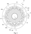
- Fig. 3 is a sectional view along the line III-III in Fig. 2 .
- the hydraulic motor 15 includes a stationary block 16 and an output rotatable block 18.
- the stationary block 16 is substantially shaped like a circular column and fixedly attached to the main body of the construction machine.
- the output rotatable block 18 is rotatably supported by the stationary block 16 via bearings 17a and 17b.
- the output rotatable block 18 is substantially shaped like a circular tube.
- the output rotatable block 18 is coupled with the traveling drive unit, which is, for example, the crawler 5 of the construction machine (see Fig. 1 ).
- the output rotatable block 18 constitutes a first block
- the stationary block 16 constitutes a second block.
- the stationary block 16 and output rotatable block 18 are arranged such that the central axis of the stationary block 16 coincides with the axis of rotation of the output rotatable block 18.
- the central axis and the axis of rotation are collectively referred to as a first axis c1.
- the term "axial direction” may refer to a direction parallel to the first axis c1
- the term “circumferential direction” may refer to the direction of the rotation of the output rotatable block 18
- the term “radial direction” may refer to the radial direction of the output rotatable block.
- the stationary block 16 includes a large diameter portion 16L and a small diameter portion 16S.
- the large diameter portion 16L faces a first direction (located on the left side in Fig. 2 ) in the axial direction.
- the small diameter portion 16S faces a second direction opposite to the first direction (located on the right side in Fig. 2 ) in the axial direction.
- the outer diameter of the small diameter portion 16S is less than that of the large diameter portion 16L.
- the large diameter portion 16L and small diameter portion 16S are coaxially arranged and form a single piece.
- the small diameter portion 16S is received in the tubular portion of the output rotatable block 18 that faces the first direction.
- the small diameter potion 16S thus rotatably supports the output rotatable block 18 via the bearings 17a and 17b.
- the stationary block 16 has an outer flange 16Lf projecting outward in the radial direction.
- the outer flange 16Lf forms a part of the large diameter portion 16L.
- the outer flange 16Lf is fixedly secured using bolts or the like onto the main body of the construction machine, so that the hydraulic motor 15 can be attached to the construction machine.
- a channel block 19 is attached to the end of the stationary block 16 facing the first direction.
- the channel block 19 has a feeding channel and a discharging channel accommodated therein.
- a hydraulic fluid is fed through the feeding channel and discharged through the discharging channel.
- the channels accommodated within the channel block 19 are connected to a reservoir tank and a pump device, which are not shown.
- the reservoir tank is configured to store the hydraulic fluid
- the pump device is configured to pump out the hydraulic fluid.
- the output rotatable block 18 includes a first tubular portion 18F, a second tubular portion 18S, a feeding and discharging plate 18P, an end cover 18C.
- the first tubular portion 18F is arranged at the end facing the second direction.
- the first tubular portion 18F is substantially shaped like a circular tube.
- the second tubular portion 18S is arranged at the end facing the first direction.
- the feeding and discharging plate 18P is sandwiched between the first and second tubular portions 18F and 18S.
- the feeding and discharging plate 18P is shaped like a perforated disc.
- the end cover 18C closes the opening of the first tubular portion 18F from the second direction side.
- the end cover 18C, first tubular portion 18F, feeding and discharging plate 18P and second tubular portion 18S are combined together using a fastening bolt 20 extending in the axial direction.
- the output rotatable block 18 has an outer flange 18Sf projecting outward in the radial direction.
- the outer flange 18Sf constitutes part of the end of the second tubular portion 18S facing the first direction.
- the outer flange 18Sf is coupled and fastened using bolts and the like with the traveling drive unit of the construction machine (for example, the crawler 5 shown in Fig. 1 ).
- the bearings 17a and 17b, which rotatably support the output rotatable block 18, are arranged between the small diameter portion 16S of the stationary block 16 and the inner surface of the second tubular portion 18S.
- the reference numerals 21a and 21b in Fig. 2 indicate mechanical seals.
- the mechanical seals 21a and 21b seal the abutting portions between the large diameter portion 16L of the stationary block 16 and the second tubular portion 18S of the output rotatable block 18.
- the first tubular portion 18F constitutes the tubular portion of the first block.
- the first tubular portion 18F constitutes a block inner circumferential portion of the first block.
- the inner circumferential surface of the first tubular portion 18F has a plurality of pin grooves 18Fg arranged at equal intervals in the circumferential direction.
- the pin grooves 18Fg extend in the axial direction.
- the pin grooves 18Fg have a semicircular shape when seen in the axial direction.
- Each pin groove 18Fg receives an internal tooth pin 22 therein.
- the internal tooth pins 22 are shaped like a circular column and housed in a rotatable manner.
- the internal tooth pins 22 radially inwardly protrude beyond the inner circumferential surface of the first tubular portion 18F and the protruding portions of the internal tooth pins 22 are also shaped like a semicircle.
- the internal tooth pins 22 serve as internal teeth meshing with external teeth 30a of an oscillatory rotating body 30, which will be described below.
- the oscillatory rotating body 30 has a diameter smaller than the maximum inner diameter of the first tubular portion 18F.
- a plurality of working chambers 35a and 35b are formed between the first tubular portion 18F and the oscillatory rotating body 30 and arranged next to each other in the circumferential direction.
- the working chambers 35a and 35b are closed by the feeding and discharging plate 18 at the first direction side.
- the working chambers 35a and 35b are closed by the end cover 18C at the second direction side.
- the feeding and discharging plate 18P has a plurality of through holes through which the hydraulic fluid is supplied into and discharged from the working chambers 35a and 35b.
- the feeding and discharging plate 18P has an annular shape when viewed in the axial direction.
- the inner edge portion of the feeding and discharging plate 18P is positioned radially inside the inner circumferential surface of the first and second tubular portions 18F and 18S.
- the above-mentioned through holes extend through the inner edge portion of the feeding and discharging plate 18P in the thickness direction.
- the through holes are open toward the concave spaces facing inward and formed between adjacent ones of the internal tooth pins 22 arranged on the inner circumferential surface of the first tubular portion 18F.
- An annular slidable plate 23 abuts against the inner edge portion of the first-direction-side end surface of the feeding and discharging plate 18P.
- the slidable plate 23 is supported on the second-direction-side end surface of the small diameter portion 16S of the stationary block 16 while being not allowed to rotate.
- the slidable plate 23 is pressed by a bias member, which is not shown, against the end surface of the feeding and discharging plate 18P and allowed to move in the axial direction.
- the slidable plate 23 has feeding communication holes in communication with the feeding channel 24 and discharging communication holes in communication with the discharging channel 25.
- the feeding and discharging communication holes are arranged to draw a ring.
- the communication holes are positioned on the circle having the same radius as the circle described by the through holes in the feeding and discharging plate 18P.
- the number of the communication holes is smaller by one than the number of the through holes in the feeding and discharging plate 18P.
- the slidable plate 23 works coordinately with the feeding and discharging plate 18P to change the position where the feeding and discharging channels 24 and 25 communicate with the working chambers 35a and 35b, in the direction of the oscillatory rotation of the oscillatory rotating body 30.
- the slidable plate 23 and feeding and discharging plate 18P constitute the channel changing unit.
- the feeding channel 24 is connected to the source portion of the hydraulic fluid of the circuit housed within the channel block 19.
- the feeding channel 24 is formed in the stationary block 16.
- the discharging channel 25 is connected to the collector portion of the hydraulic fluid of the circuit housed within the channel block 19.
- the discharging channel 25 is formed in the stationary block 16, like the feeding channel 24.
- the oscillatory rotating body 30 is disposed such that it can oscillatorily rotate.
- the oscillatory rotating body 30 is configured to oscillatorily rotate on the first axis c1 at a predetermined pivot radius.
- the outer circumferential surface of the oscillatory rotating body 30 faces in the radial direction the internal tooth pins 22 of the first tubular portion 18F.
- the external teeth 30a of the oscillatory rotating body 30 mesh with the internal tooth pins 22 of the first tubular portion 18F.
- the number of the external teeth 30a of the oscillatory rotating body 30 is slightly less than the number of the internal tooth pins 22 of the first tubular portion 18F. For example, the number of the external teeth 30a is smaller by one than the number of the internal tooth pins 22.
- the oscillatory rotating body 30 While the oscillatory rotating body 30 is oscillatorily rotating, the external teeth 30a constantly remain in contact with the internal teeth of the first tubular portion 18F (internal tooth pins 22) at a portion between the tooth tip and the tooth root. In this manner, the two working chambers 35a and 35b are roughly defined between the inner circumferential surface of the first tubular portion 18F and the external teeth 30a of the oscillatory rotating body 30. In the region surrounding the oscillatory rotating body 30, the two working chambers 35a and 35b are line symmetrical to each other when seen in the axial direction.
- the working chambers 35a and 35b are in communication with the feeding and discharging channels 24 and 25 via the through holes in the feeding and discharging plate 18P.
- the hydraulic fluid is fed to and discharged from the working chambers 35a and 35b such that the oscillatory rotating body 30 can oscillatorily rotate.
- the two working chambers 35a and 35b move in the circumferential direction in the direction of the oscillatory rotation of the oscillatory rotating body 30.
- the feeding and discharging plate 18P has a circular guide hole 26 extending through the feeding and discharging plate 18P in the axial direction.
- the guide hole 26 is formed in the radially inner portion of the feeding and discharging plate 18P.
- a rotation converting block 28 is rotatably supported via a bearing 27, which is a needle bearing or the like.
- the rotation converting block 28 is a substantially tubular member shaped like a stepped circular cylinder.
- the rotation converting block 28 includes a large diameter tubular portion 28a and a small diameter tubular portion 28b.
- the large diameter tubular portion 28a faces the second direction.
- the small diameter tubular portion 28b is integrated with the large diameter tubular portion 28a and positioned on the first direction side of the large diameter tubular portion 28a.
- the outer circumferential surface of the large diameter tubular portion 28a is circular and centered on the same point as the outer and inner circumferential surfaces of the small diameter tubular portion 28b.
- the inner circumferential surface 28ai of the large diameter tubular portion 28a is circular, but centered on a point shifted from the center of the circular outer circumferential surface (first axis c1). In other words, the inner circumferential surface 28ai of the large diameter tubular portion 28a is centered on a different point than the guide hole 26 of the feeding and discharging plate 18P.
- the oscillatory rotating body 30 has a spline hole 31 of a predetermined inner diameter at the center thereof.
- the spline hole 31 has a plurality of splines on the inner surface so as to extend in the axial direction.
- the spline hole 31 receives therein the end of a rotation restricting shaft 32 that faces the second direction.
- the rotation restricting shaft 32 will be described below. In Fig. 2 , the rotation restricting shaft 32 is represented by the dotted line for the sake of convenience.
- the oscillatory rotating body 30 has a boss 33 shaped like a circular tube and protruding toward the first direction from the inner circumferential edge of the oscillatory rotating body 30 that faces the first direction.
- the boss 33 is seamlessly formed on the oscillatory rotating body 30.
- the boss 33 is received in the inner circumferential surface 28ai of the large diameter tubular portion 28a of the rotation converting block 28.
- the boss 33 is rotatably supported by the inner circumferential surface 28ai of the large diameter tubular portion 28a via a bearing 34, which is a needle bearing or the like.
- the amount of eccentricity of the inner circumferential surface 28ai of the large diameter tubular portion 28a from the first axis c1 is equal to the radius of the pivot of the oscillatory rotating body 30 about the first axis c1. In this manner, while being allowed to oscillatorily rotate, the oscillatory rotating body 30 is supported by the feeding and discharging plate 18P via the rotation converting block 28 and bearings 34 and 27.
- the rotation of the rotation converting block 28 caused by the pivot (oscillatory rotation) of the oscillatory rotating body 30 is the result of extracting the oscillation component of the oscillatory rotating body 30 as the synchronous rotation about the first axis c1.
- the rotation converting block 28 can extract the oscillation component of the oscillatory rotating body 30 as the synchronous rotation about the first axis c1.
- the stationary block 16 has a device housing hole 36 in the radially central region.
- the device housing hole 36 extends through the stationary block 16 in the axial direction.
- a spline block 37 substantially shaped like a circular tube is provided at the substantially middle portion in the axial direction.
- the spline block 37 is seamlessly coupled with the stationary block 16.
- the spline block 37 has a spline hole 38.
- the axis of the spline hole 38 coincides with the first axis c1.
- a plurality of splines extend in the axial direction on the inner circumferential surface of the spline hole 38.
- the spline hole 38 receives therein the end of the rotation restricting shaft 32 that faces the first direction.
- the rotation restraining shaft 32 is a shaft member extending from the inner circumferential portion of the oscillatory rotating body 30 in the direction intersecting the radial direction.
- the rotation restricting shaft 32 couples the oscillatory rotating body 30 to the stationary block 16 (second block) such that the oscillatory rotating body 30 is prevented from rotating relative to the stationary block 16 (second block), while allowing oscillatory rotation of the oscillatory rotating body 30.
- the rotation restricting shaft 32 has a first external spline 32F on the outer periphery of its end facing the first direction and also has a second external spline 32S on the outer periphery of its end facing the second direction.
- the first and second external splines 32F and 32S both have a greater outer diameter than the middle region of the rotational restricting shaft 32 in the axial direction.
- the first and second external splines 32F and 32S each have a spline tooth.
- the middle region in the axial direction is the most raised portion outwardly in the radial direction. This region is referred to as the maximally raised portion.
- Each spline tooth is substantially shaped like an arc. To be specific, the height of the tooth surface gently decreases from the maximally raised portion to the respective ends in the axial direction.
- the first external spline 32F of the rotation restricting shaft 32 meshes with the spline hole 38 in the spline block 37.
- the second external spline 32S of the rotation restricting shaft 32 meshes with the spline hole 31 in the oscillatory rotating body 30. In this manner, the rotation of the oscillatory rotating body 30 (on its own axis) is restricted by the stationary block 16.
- the spline tooth of the first external spline 32F of the rotation restricting shaft 32 is inclined within the spline hole 38 in the radial direction.
- the spline tooth of the second external spline 32S is inclined within the spline hole 31 in the radial direction.
- the reference numeral c2 in Fig. 2 indicates the axis of the rotation restricting shaft 32.
- the axis c2 of the rotation restricting shaft 32 intersects with the first axis c1 about which the output rotatable block 18 can rotate at the position coinciding with substantially the center of the spline block 37.
- the axis c2 forms a predetermined angle relative to the first axis c1 at the intersection.
- a plate housing chamber 39 is defined between the front surface of the channel block 19 and the spline block 37.
- the plate housing chamber 39 is positioned on the first direction side with respect to the spline block 37.
- a press plate 40 shaped like a disc is housed together with a bias spring 98 (bias device), which is configured to bias the press plate 40 toward the second direction.
- a cylinder chamber 41 is defined.
- a piston device 45 is provided in the cylinder chamber 41.
- the piston device 45 has a piston 42 slidably housed therein.
- the piston 42 is housed in the cylinder chamber 41 such that it is movable forward and backward in the axial direction.
- the piston 42 has a coupling rod 43 to couple the piston 42 to the press plate 40.
- the coupling rod 43 couples together the press plate 40 and piston 42. In this manner, the press plate 40 and piston 42 are integrally movable in the axial direction.
- the piston 42 is subject to the bias force applied by the bias spring 98 via the press plate 40 and coupling rod 43.
- the piston 42 defines a space facing the second direction, which is connected to a pressure inlet channel 44.
- the piston 42 is pushed toward the first direction by the pressure produced by the hydraulic fluid flowing into the cylinder chamber 41 though the pressure inlet channel 44.
- the piston 42 is coupled with the press plate 40.
- the press plate 40 thus overcomes the bias force applied by the bias spring 98 and moves backward toward the first direction.
- the piston device 45 including the cylinder chamber 41 and piston 42 constitutes a brake release device when combined with the pressure inlet channel 44.
- the small diameter tubular portion 28b of the rotation converting block 28 supported by the feeding and discharging plate 18P is disposed in the region facing the second direction with respect to the spline block 37.
- a plurality of stationary friction plates 55 shaped like a ring are provided in the region facing the outer circumferential surface of the small diameter tubular portion 28b.
- the stationary friction plates 55 are mounted on the inner periphery of the device housing hole 36 such that they are movable in the axial direction but not allowed to rotate relative to the inner periphery.
- the inner circumferential surface of the device housing hole 36 have a plurality of slit grooves along the axial direction, for example, and the stationary friction plates 55 have a plurality of claws on their outer circumferential portion. The claws are inserted in the slit grooves. The last friction plate 55 on the second direction side is prevented from moving toward the second direction by a restricting member fixedly attached to the stationary block 16.
- a plurality of rotatable friction plates 56 shaped like a ring are provided on the outer periphery of the small diameter tubular portion 28b of the rotation converting block 28, a plurality of rotatable friction plates 56 shaped like a ring are provided.
- the rotatable friction plates 56 are represented by the dotted line for the sake of convenience.
- the rotatable friction plates 56 are mounted on the outer periphery of the small diameter tubular portion 28b such that they are movable in the axial direction but not allowed to rotate relative to the outer periphery.
- the outer circumferential surface of the small diameter tubular portion 28b has a plurality of slit grooves along the axial direction, for example, and the rotatable friction plates 56 have a plurality of claws on their inner circumferential portion.
- the rotatable friction plates 56 constitute a first friction plate configured to rotate together with the oscillatory rotating body 30, and the stationary friction plates 55 constitute a second friction plate prevented from rotating by the second or first block.
- the stationary friction plates 55 serving as the second friction plate are prevented from rotating by the stationary block 16 serving as the second block.
- the stationary and rotatable friction plates 55 and 56 are alternately arranged next to each other in the axial direction within the space defined in the device housing hole 36 by the rotation converting block 28.
- the last friction plate 55 on the first direction side is acted upon from outside by a pressing force directed toward the second direction, the alternately arranged stationary and rotatable friction plates 55 and 56 frictionally touch each other at their opposing surfaces.
- the pressing force thus produces a brake force to act on the rotation converting block 28.
- the rotation converting block 28 is configured to rotate in response to the oscillatory rotation of the oscillatory rotating body 30. Therefore, the oscillatory rotation of the oscillatory rotating body 30 is braked by the braking effect realized by the stationary and rotatable friction plates 55 and 56.
- the spline block 37 which is substantially shaped like a circular tube, has a plurality of insertion holes 49 extending through the spline block 37 in the axial direction.
- the insertion holes 49 are arranged at equal intervals in the circumferential direction, for example.
- the insertion holes 49 receive pressing rods 50 such that they are movable in the axial direction.
- the pressing rods 50 have a greater length in the axial direction than the spline block 37.
- Each pressing rod 50 is configured such that its end facing the first direction can abut against the end surface of the press plate 40 placed in the plate housing chamber 39.
- Each pressing rod 50 is configured such that its end facing the second direction can abut against the last friction plate 55 on the first direction side via an intervening member such as a washer.
- the press plate 40 and pressing rods 50 constitute a press member configured to apply a press force to the rotatable friction plates 56 (first friction plate) and stationary friction plates 55 (second friction plate).
- the bias spring 98 constitutes a bias device configured to bias the press member.
- the piston device 45 constitutes a brake release device configured to move the press member in such a direction that the frictional contact between the rotatable friction plates 56 (first friction plate) and the stationary friction plates 55 (second friction plate) is undone.
- a press mechanism is constituted by the press plate 40 and pressing rods 50 serving as the press member, the bias spring 98 serving as the bias device, and the piston device 45 serving as the brake release device.
- the press mechanism constitutes a brake mechanism 48 relating to the present embodiment when combined with the stationary and rotatable friction plates 55 and 56.
- the rotation restricting shaft 32 is disposed in the hydraulic motor 15 in the middle region in the axial direction while meshing with the spline hole 38 in the spline block 37, which is disposed in the stationary block 16 in the substantially middle portion in the axial direction, and also meshing with the spline hole 31 in the oscillatory rotating body 30.
- the main constituents of the brake mechanism 48 are arranged in the region surrounding the rotation restricting shaft 32. Specifically, in the region surrounding the rotation restricting shaft 32, the stationary friction plates 55, rotatable friction plates 56, and part of the pressing rods 50 are disposed. In the region surrounding the rotation restricting shaft 32, the stationary friction plates 55, rotatable friction plates 56, and some of the pressing rods 50 overlap the rotation restricting shaft 32 in the axial direction.
- the hydraulic fluid in the feeding channel 24 flows sequentially into the working chambers 35a and 35b through the slidable plate 23 and feeding and discharging plate 18P.
- the pressure created by the hydraulic fluid causes the oscillatory rotating body 30 to oscillatorily rotate in a predetermined direction. Since the external teeth 30a of the oscillatory rotating body 30 engage with the internal tooth pins 22 of the first tubular portion 18F, the first tubular portion 18F follows the oscillatory rotation of the oscillatory rotating body 30 and rotates at a speed reduced by a predetermined reduction ratio. As a result, the output rotatable block 18 including the first tubular portion 18F rotates at the speed reduced by the predetermined reduction ratio.
- the block (18) corresponding to the first block including the block inner circumferential portion and the plurality of internal teeth provided on the block inner circumferential portion serves as the output rotatable block
- the block (16) corresponding to the second block, which is coupled with the oscillatory rotating body 30 via the rotation restricting shaft 32 serves as the stationary block
- the block (18) corresponding to the first block including the block inner circumferential portion and the plurality of internal teeth provided on the block inner circumferential portion may serve as the stationary block
- the block (16) corresponding to the second block, which is coupled with the oscillatory rotating body 30 via the rotation restricting shaft 32 may serve as the output rotatable block.
- the block corresponding to the output rotatable block 18 shown in Fig. 2 is fixedly attached to the main body of the construction machine.
- the rotation of the oscillatory rotating body 30 on its own axis is transmitted via the rotation restricting shaft 32 to the block corresponding to the stationary block 16 shown in Fig. 2 .
- the block equivalent to the stationary block 16 shown in Fig. 2 then rotates at the speed reduced by a predetermined reduction ratio, and the rotation is output.
- the block corresponding to the first block which includes the block inner circumferential portion and the plurality of internal teeth provided on the block inner circumferential portion, may serve as the stationary block.
- the block corresponding to the second block which is coupled with the oscillatory rotating body 30 via the rotation restricting shaft 32, may serve as the output rotatable block.
- the brake mechanism 48 includes the rotatable friction plates 56 (first friction plate), stationary friction plates 55 (second friction plate), and press mechanism (press plate 40, pressing rods 50, bias spring 98, piston device 45 and the like).
- the oscillatory rotation of the oscillatory rotating body 30 is braked by the press mechanism pressing the stationary and rotatable friction plates 55 and 56 against each other. Accordingly, the hydraulic motor 15 relating to the present embodiment can smoothly and reliably apply and remove a brake force onto the oscillatory rotating body 30.
- the stationary and rotatable friction plates 55 and 56 are annularly shaped and provided in the region surrounding the rotation restricting shaft 32. Accordingly, a large braking torque can be efficiently produced in the region surrounding the rotation restricting shaft 32.
- the hydraulic motor 15 relating to the present embodiment includes the rotation converting block 28 configured to extract the oscillation component of the rotation of the oscillatory rotating body 30 as the synchronous rotation about the first axis c1.
- the rotatable friction plates 56 of the brake mechanism 48 are supported by the rotation converting block 28 in such a manner that the rotatable friction plates 56 are not allowed to rotate relative to the rotation converting block 28. Accordingly, the oscillation component of the rotation of the oscillatory rotating body 30 can be extracted as the rotation of the rotation converting block 28, and the brake mechanism 48 can apply a braking force onto the rotation converting block 28. In this case, the required braking torque can be reduced when compared with the case where the braking torque is directly applied to the oscillatorily rotating oscillatory rotating body 30. Accordingly, the brake mechanism 48 can be reduced in size by employing the present embodiment.
- the press mechanism of the brake mechanism 48 is constituted by the press member (the press plate 40 and pressing rods 50), the bias device (bias spring 98) configured to bias the press member in the braking direction, and the brake release device (piston device 45) configured to move the press member in the brake release direction.
- the oscillatory rotating body 30 can be reliably braked and the braking can be reliably released in a simplified manner in the present embodiment.
- the brake release device is constituted by the piston device 45 configured to move the press member in the friction removing direction using the pressured produced by the introduced hydraulic fluid. While the hydraulic motor 15 is in operation, the force created by the hydraulic fluid rises and the braking applied onto the oscillatory rotating body 30 is automatically released. While the hydraulic motor 15 is suspended from operating, the force created by the hydraulic fluid drops and the oscillatory rotating body 30 is reliably braked.
- users are thus not required to do something special to brake the oscillatory rotating body 30 and release the braking and can enjoy convenience.
- the main constituents of the brake mechanism 48 are disposed in the region surrounding the rotation restricting shaft 32.
- the main constituents of the brake mechanism 48 are disposed in a sufficiently spacious region, to be specific, in the region externally surrounding the rotation restricting shaft 32. In this manner, while an increase in the overall size of the hydraulic motor 15 is prevented, the brake mechanism 48 can have an increased volume. Accordingly, the hydraulic motor 15 relating to the present embodiment can smoothly and reliably apply and remove a brake force onto the oscillatory rotating body 30.
- Fig. 4 is a vertical sectional view showing a hydraulic motor (hydraulic device) according to a modification example.
- a hydraulic motor 15A relating to the present modification example is basically configured in substantially the same manner as the hydraulic motor 15 relating to the above-described embodiment.
- the bias spring 98 is disposed together with the press plate in the plate housing chamber 39 defined within the stationary block 16. According to the present modification example, the bias spring 98 is disposed in the cylinder chamber 41 behind the piston 42 (on the first direction side with respect to the piston 42).
- a plurality of bias springs 98 can be contained in a limited space when compared with the case where the bias spring 98 surrounds the coupling rod 43 in the plate housing chamber 39 (see Fig. 2 ). Accordingly, the hydraulic motor 15A relating to the present modification example can achieve a reduced size.
- Fig. 5 is a vertical sectional view showing part of a hydraulic motor (hydraulic device) according to a second embodiment.
- a hydraulic motor 115 relating to the present embodiment is basically configured in substantially the same manner as the hydraulic motor 15 relating to the above-described first embodiment.
- the second embodiment is different from the first embodiment in terms of how the rotation converting block 28 configured to extract the oscillatory rotation of the oscillatory rotating body 30 as the synchronous rotation about the first axis c1 is arranged and how to extract the rotation.
- the end of the oscillatory rotating body 30 has the boss 33, and the eccentric inner circumferential surface 28ai of the rotation converting block 28 is rotatably supported by the outer circumferential surface of the boss 33.
- the outer circumferential surface of the rotation restricting shaft 32 has a spherically raised portion 51 in its half facing the second direction, and a plain bearing 52 having a recessed spherical inner surface is fixedly mounted on the inner surface 28ai of the large diameter tubular portion 28a of the rotation converting block 28.
- the plain bearing 52 is fixedly mounted on the inner surface 28ai of the large diameter tubular portion 28a that is centered on a point shifted in the radial direction from the first axis c1.
- the plain bearing 52 has a recessed spherical surface.
- the plain bearing 52 has a recessed spherical inner surface 52a.
- the surface 52a is in contact with the raised portion 51 of the rotation restricting shaft 32 with sliding being allowed between them.
- the sliding on the spherical surface 52a allows the rotation restricting shaft 32 to yaw.
- the plain bearing 52 and rotation converting block 28 are configured to extract the oscillatory rotation of the raised portion 51 of the rotation restricting shaft 32 as the synchronous rotation about the first axis c1.
- the hydraulic motor 115 relating to the second embodiment is different from the hydraulic motor 15 relating to the first embodiment in terms of how the rotation converting block 28 is arranged and how to extract the oscillation component. Except for that, the hydraulic motor 115 is the same as the hydraulic motor 15 relating to the first embodiment. Therefore, the hydraulic motor 115 of the second embodiment can also produce the same advantageous effects as the hydraulic motor 15 relating to the above-described first embodiment.
- Fig. 6 is a vertical sectional view showing a hydraulic motor (hydraulic device) according to a third embodiment.
- Fig. 7 is an enlarged view of the main part of Fig. 6 and shows how the hydraulic motor works.
- Fig. 6 illustrates the brake mechanism in operation.
- Fig. 7 illustrates the brake mechanism suspended.
- a hydraulic motor 215 relating to the present embodiment is basically configured in substantially the same manner as the hydraulic motor 15 relating to the above-described first embodiment.
- the third embodiment is different from the first embodiment in terms of the press mechanism of the brake mechanism 248.
- the rotatable friction plates 56 (first friction plate) and stationary friction plates 55 (second friction plate) are the same as in the first embodiment.
- the press mechanism is constituted by a press plate 240 serving as the press member, a bias spring 298 configured to bias the press plate 240 in the braking direction, and a piston device 245 (brake release device) configured to move the press plate 240 in the brake release direction.
- the press mechanism is disposed in the region facing the second direction with respect to the spline block 37.
- the piston device 245 includes an annular stationary wall 57 fixedly attached to the inner surface of the device housing hole 36 and a tubular piston 58 having an end flange 58a.
- the tubular piston 58 has a tubular wall 58b and the end flange 58a.
- the tubular wall 58b is in slidable contact with the inner circumferential surface of the stationary wall 57, and the end flange 58a projects radially outwardly from the end of the tubular wall 58b facing the first direction.
- the tubular piston 58 is assembled in the device housing hole 36 such that the outer circumferential surface of the end flange 58a is in slidable contact with the inner circumferential surface of the device housing hole 36.
- the space defined between the end flange 58a of the tubular piston 58 and the stationary wall 57 is referred to as a piston chamber 59 into which the hydraulic fluid flows through the pressure inlet channel 44.
- the press plate 240 has an annular tubular portion 240a and a restricting flange 240b projecting radially inward from the end of the tubular portion 240a that faces the first direction.
- the restricting flange 240b surrounds the outer periphery of the tubular piston 58.
- the press plate 240 is configured not to move further in the second direction beyond a stopper ring 60 fixedly attached to the end of the outer periphery of the tubular piston 58 that faces the second direction.
- the bias spring 298 is disposed between the stationary wall 57 of the piston device 245 and the press plate 240.
- the end of the tubular portion 240a of the press plate 240 is configured to abut against the last friction plate 55 on the first direction side.
- the bias spring 298 biases the press plate 240 in such a direction that the friction pates 55 and 56 are pressed against each other.
- the bias spring 298 applies a press force to the stationary and rotatable friction plates 55 and 56 via the press plate 240. This results in braking the rotation of the rotation converting block 28, thereby braking the oscillatory rotation of the oscillatory rotating body 30.
- the high-pressure hydraulic fluid flows into the piston chamber 59 through the pressure inlet channel 44.
- the pressure applied by the hydraulic fluid causes the tubular piston 58 to overcome the bias force applied by the bias spring 298 and to retreat.
- no frictional force is exerted between the stationary and rotatable friction plates 55 and 56, thereby allowing the rotation converting block 28 and oscillatory rotating body 30 to freely rotate.
- the hydraulic motor 215 relating to the third embodiment is basically configured in substantially the same manner as the hydraulic motor 15 relating to the first embodiment and can basically produce the same effects as the hydraulic motor 15 relating to the first embodiment.
- the piston device 245 and bias device (bias spring 298) of the brake mechanism 248 are provided in the region surrounding the rotation restricting shaft 32. This means that the main constituents of the brake mechanism 248 overlap the rotation restricting shaft 32 in the axial direction. Accordingly, the hydraulic motor 215 relating to the present embodiment can have a reduced overall size in the axial direction.
- Figs. 8A and 8B are vertical sectional views showing part of a hydraulic motor 215A (hydraulic device) according to a modification example of the third embodiment.
- Fig. 8A illustrates a brake mechanism 248A in operation.
- Fig. 8B illustrates the brake mechanism 248A suspended.
- the hydraulic motor 215A relating to the present modification example is basically configured in substantially the same manner as the hydraulic motor 215 relating to the above-described third embodiment but slightly different in terms of the configuration of the brake mechanism 248A.
- bias spring 298 is arranged between the stationary wall 57 and the press plate 240 in the third embodiment
- the bias spring 298 is arranged between the spline block 37 and the tubular piston 58 of the piston device 245A in the present modification example.
- the press plate 240A is fixedly attached to or configured to abut against the end surface of the tubular piston 58 facing the second direction.
- the present modification example can also produce the same effects as the above-described third embodiment.
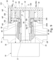
- Fig. 9 is a vertical sectional view showing a hydraulic motor 315 (hydraulic device) according to a fourth embodiment.
- Fig. 10 is an enlarged view of the main part of Fig. 9 and shows how the hydraulic motor 315 works.
- Fig. 9 illustrates a brake mechanism 348 in operation.
- Fig. 10 illustrates the brake mechanism 348 being suspended.
- the hydraulic motor 315 relating to the fourth embodiment is configured in substantially the same manner as the hydraulic motor 15 relating to the above-described first embodiment.
- a friction plate 356 of the brake mechanism 348 (first friction plate) is fixedly fastened using bolts or the like onto the end surface of the oscillatory rotating body 30 in the axial direction.
- the hydraulic motor 315 relating to the present embodiment is implemented without the rotation converting block configured to extract the oscillatory rotation of the oscillatory rotating body 30 as the synchronous rotation about the first axis c1.
- the brake mechanism 348 includes a friction plate 356 (first friction plate), a friction plate 355 (second friction plate) and a press mechanism.
- the press mechanism is configured to press the rotatable friction plates 356 and 355.
- the press mechanism includes a bias spring 298 and a piston device 245A, which are configured in the same manner as those in the modification example of the third embodiment.
- the piston device 245A includes an annular stationary wall 57 fixedly attached to the inner surface of the device housing hole 36 and a tubular piston 58 having an end flange 58a.
- the stationary wall 57 is fixedly attached to a portion of the device housing hole 36 near its end facing the second direction.
- the tubular piston 58 has a tubular wall 58b and the end flange 58a.
- the tubular wall 58b is in slidable contact with the inner circumferential surface of the stationary wall 57, and the end flange 58a projects radially outwardly from the end of the tubular wall 58b facing the first direction.
- the tubular piston 58 is assembled in the device housing hole 36 such that the outer circumferential surface of the end flange 58a is in slidable contact with the inner circumferential surface of the device housing hole 36.
- the space defined between the end flange 58a of the tubular piston 58 and the stationary wall 57 is referred to as a piston chamber 59 into which the hydraulic fluid flows through the pressure inlet channel 44.
- the annular friction plate 355 is fixedly fastened using bolts or the like onto the end surface of the tubular wall 58b of the tubular piston 58 facing the second direction.
- the end surface (facing the second direction) of the friction plate 355 fixedly attached to the tubular wall 58b faces the end surface (facing the first direction) of the friction plate 356 fixedly attached to the end surface of the oscillatory rotating body 30.
- a portion of the tubular wall 58b of the tubular piston 58 also serves as a press member.
- the bias spring 298 is disposed between the spline block 37 and the end flange 58a of the tubular piston 58 and configured to bias the tubular piston 58 toward the second direction.
- the bias spring 298 biases the tubular piston 58 in such a manner that the friction plate 355 attached to the tubular piston 58 may be pressed against the friction plate 356.
- the high-pressure hydraulic fluid flows into the piston chamber 59 through the pressure inlet channel 44.
- the pressure applied by the hydraulic fluid causes the tubular piston 58 to overcome the bias force applied by the bias spring 298 and to move backward.
- no frictional force is exerted between the stationary and rotatable friction plates 355 and 356, thereby allowing the oscillatory rotating body 30 to freely rotate.
- the hydraulic motor 315 relating to the fourth embodiment is basically configured in substantially the same manner as the hydraulic motor 15 relating to the first embodiment and can basically produce the same effects as the hydraulic motor 15 relating to the first embodiment.
- the hydraulic motor 315 relating to the fourth embodiment is configured such that the braking torque may be directly applied to the oscillatory rotating body 30 configured to oscillatorily rotate.
- the hydraulic motor 315 relating to the fourth embodiment can thus achieve a smaller number of parts than the hydraulic motor including the rotation converting block. Accordingly, the hydraulic motor 315 relating to the present embodiment can achieve a reduced cost.
- Fig. 11 is a vertical sectional view showing a hydraulic motor 415 (hydraulic device) according to a fifth embodiment.
- Fig. 12 is an enlarged view of the main part of Fig. 11 and shows how the hydraulic motor 415 works.
- Fig. 11 illustrates the brake mechanism in operation.
- Fig. 12 illustrates the brake mechanism suspended.
- the hydraulic motor 415 relating to the fifth embodiment is also configured in substantially the same manner as the hydraulic motor 15 relating to the above-described first embodiment.
- a plurality of rotatable friction plates 456 (first friction plate) of the brake mechanism 448 are attached to the outer periphery of the rotation restricting shaft 32.
- a plurality of stationary friction plates 455 (second friction plate) of the brake mechanism 448 are attached to the inner circumferential surface of the device housing hole 36 in the stationary block 16 as in the first embodiment.
- the hydraulic motor 415 relating to the present embodiment is also implemented without the rotation converting block configured to extract the oscillatory rotation of the oscillatory rotating body 30 as the synchronous rotation about the first axis c1.
- the stationary friction plates 455 are mounted on the inner circumferential portion of the device housing hole 36 such that they are movable in the axial direction but not allowed to rotate relative to the inner circumferential portion.
- the inner circumferential surface of the device housing hole 36 has a plurality of slit grooves along the axial direction, for example, and the stationary friction plates 455 have a plurality of claws on their outer circumferential portion. The claws are inserted in the slit grooves.
- the rotatable friction plates 456 are mounted on the outer circumferential portion of the rotation restricting shaft 32 such that they are movable in the axial direction but not allowed to rotate relative to the outer circumferential portion.
- the outer circumferential surface of the rotation restricting shaft 32 has a plurality of slit grooves along the axial direction, for example, and the rotatable friction plates 456 have a plurality of claws on their inner circumferential portion. The claws are inserted in the slit grooves.
- the press mechanism constituting part of the brake mechanism 448 includes the bias spring 298 and piston device 245A, which are configured in the same manner as in the fourth embodiment.
- the piston device 245A is not described in detail here for the sake of brevity.
- the end of the tubular wall 58b of the tubular piston 58 that faces the second direction also serves as a press member.
- the bias spring 298 applies a press force to the stationary and rotatable friction plates 455 and 456 via the tubular piston 58.
- a frictional force is exerted between the stationary and rotatable friction plates 455 and 456, thereby braking the oscillatory rotation of the oscillatory rotating body 30 and rotation restricting shaft 32.
- the high-pressure hydraulic fluid flows into the piston chamber 59 through the pressure inlet channel 44.
- the pressure applied by the hydraulic fluid causes the tubular piston 58 to overcome the bias force applied by the bias spring 298 and to move backward.
- no frictional force is exerted between the stationary and rotatable friction plates 455 and 456, thereby allowing the oscillatory rotating body 30 and rotation restricting shaft 32 to freely rotate.
- the hydraulic motor 415 relating to the fifth embodiment is basically configured in substantially the same manner as the hydraulic motor 15 relating to the first embodiment and can thus basically produce the same effects as the hydraulic motor 15 relating to the first embodiment.
- the hydraulic motor 415 relating to the fifth embodiment is configured to apply a braking torque to the rotation restricting shaft 32, which is configured to oscillatorily rotate synchronously with the oscillatory rotating body 30. This means that the oscillatory rotating body 30 can be braked in a simplified manner while the hydraulic motor 415 is constituted by a smaller number of parts. Accordingly, the hydraulic motor 415 relating to the present embodiment can achieve a reduced cost.
- Fig. 13 is a vertical sectional view showing a hydraulic motor 515 (hydraulic device) according to a sixth embodiment.
- Fig. 14 is an enlarged view of the main part of Fig. 13 and shows how the hydraulic motor 515 works.
- Fig. 13 illustrates a brake mechanism 548 in operation.
- Fig. 14 illustrates the brake mechanism 548 suspended.
- the hydraulic motor 515 relating to the sixth embodiment is partly configured in an analogous manner as the hydraulic motor 15 relating to the above-described first embodiment. The following description of the hydraulic motor 515 will be focused on the differences between the first and sixth embodiments.
- the hydraulic motor 515 has an output rotatable block 518 constituted by the first tubular portion 18F, which is described in the first embodiment, and a third tubular portion 18T.
- the third tubular portion 18T is next to the first tubular portion 18F on the second direction side, and the end cover 18C is arranged on the end surface of the third tubular portion 18T facing the second direction.
- the end cover 18C, third tubular portion 18T, first tubular portion 18F, feeding and discharging plate 18P and second tubular portion 18S are combined together using a fastening bolt 20 to constitute the output rotatable block 518.
- the oscillatory rotating body 30 is disposed such that it can oscillatorily rotate.
- the second tubular portion 18S is rotatably supported by the stationary block 16 via a bearing, which is not shown.
- a spline block 37 is seamlessly and fixedly provided on the inner circumferential portion of the stationary block 16.
- the oscillatory rotating body 30 and spline block 37 respectively have spline holes 31 and 38.
- the first external spline 32F of the first end of the rotation restricting shaft 32 is fitted in the spline hole 38 in the spline block 37 such that the rotation restricting shaft 32 can yaw.
- the second external spline 32S of the second end of the rotation restricting shaft 32 is fitted in the spline hole 31 in the oscillatory rotating body 30 such that the rotation restricting shaft 32 can yaw.
- a rotation converting block 528 is housed inside the third tubular portion 18T.
- the rotation converting block 528 is configured to extract the oscillation component of the oscillatory rotating body 30 as the synchronous rotation about the first axis c1.
- the rotation converting block 528 includes a block body 528L and an eccentric boss 528S.
- the block body 528L has a large diameter and shaped like a short circular column.
- the eccentric boss 528S protrudes from the end surface of the block body 528L that faces the first direction.
- the eccentric boss 528S has a smaller diameter than the block body 528L and shaped like a short circular tube.
- the eccentric boss 528S is centered on a point shifted by a certain amount in the radial direction from the central axis of the bock body 528L (first axis c1).
- the amount of eccentricity of the eccentric boss 528S is substantially equal to the pivot radius (oscillation radius) of the oscillatory rotating body 30.
- a boss 533 shaped like a circular tube protrudes toward the second direction from the inner circumferential edge of the oscillatory rotating body 30.
- the boss 533 of the oscillatory rotating body 30 protrudes in the axial direction into the inner space within the third tubular portion 18T.
- the inner circumferential surface of the boss 533 is referred to as a guide surface 533a.
- the eccentric boss 528S of the rotation converting block 528 is received by the guide surface 533a of the boss 533.
- the eccentric boss 528S is rotatably supported by the guide surface 533a via a bearing 80, which is a needle bearing or the like.
- the rotation converting block 528 specifically, the block body 528L has a support boss 62 at the center of its end surface facing the second direction.
- the support boss 62 is shaped like a circular column and centered on the same axis as the block body 528L.
- the support boss 62 is rotatably supported by the end cover 18C of the output rotatable block 518 via a bearing 81. While the rotation converting block 528 is supported by the bearing 81, the block body 528L shaped like a short circular tube is rotatable about the first axis c1.
- the eccentric boss 528S is rotatable synchronously with the oscillatory rotation (eccentric rotation) of the oscillatory rotating body 30.
- the rotation converting block 528 can thus extract the oscillation component of the oscillatory rotating body 30 as the synchronous rotation about the first axis c1.
- a plurality of second friction plates 70 shaped like a ring are attached to the inner circumferential surface of the third tubular portion 18T on the second direction side.
- the second friction plates 70 are mounted on the inner circumferential portion of the third tubular portion 18T such that they are movable in the axial direction but not allowed to rotate relative to the inner circumferential portion.
- the inner circumferential surface of the third tubular portion 18T has a plurality of slit grooves along the axial direction, for example, and the second friction plates 70 have a plurality of claws on their outer circumferential portion. The claws are inserted in the slit grooves.
- the last second friction plate 70 on the second direction side is prevented from moving toward the second direction by a restricting member.
- first friction plates 71 On the outer periphery of the block body 528L of the rotation converting block 528, a plurality of first friction plates 71 shaped like a ring are provided.
- the first friction plates 71 are mounted on the outer circumferential surface of the block body 528L such that they are movable in the axial direction but not allowed to rotate relative to the outer circumferential surface.
- the outer periphery of the block body 528L has a plurality of slit grooves along the axial direction, for example.
- the first friction plates 71 have a plurality of claws on their inner circumferential portion. The claws are inserted in the slit grooves.
- the second and first friction plates 70 and 71 are alternately arranged in the axial direction.
- the second and first friction plates 70 and 71 When an external force acts in the axial direction on the second and first friction plates 70 and 71, the second and first friction plates 70 and 71 establish a surface contact between them, thereby generating a braking force.
- the first friction plates 71 constitute the first friction plate configured to rotate together with the oscillatory rotating body 30.
- the second friction plates 70 constitute the second friction plate restricted from rotating by the second or first block.
- the second friction plates 70 are restricted from rotating by the output rotatable block 518 (third tubular portion 18T) serving as the first block.
- the third tubular portion 18T having the second friction plates 70 attached thereto is part of the output rotatable block 518 configured to receive the reduced rotation.
- the rotation converting block 528 having the first friction plates 71 attached thereto is configured to rotate synchronously with the oscillatory rotation of the oscillatory rotating body 30. Therefore, the third tubular portion 18T and rotation converting block 528 always rotate at different speeds. For this reason, if a surface contact is established between the second and first friction plates 70 and 71 as described above and the braking force is thus exerted, the third tubular portion 18T and rotation converting block 528 are locked and the oscillatory rotation of the oscillatory rotating body 30 is locked.
- the press mechanism constituting part of the brake mechanism 548 is configured in substantially the same manner as in the first embodiment. Note that, however, an end press plate 75 is provided on the inner periphery of the third tubular portion 18T to face the last second friction plate 70 on the first direction side.
- the end press plate 75 is configured to be pressed by the pressing rods 50 when they are biased by the bias spring 98 and to transmit the bias force produced by the bias spring 98 to the friction plates as the pressing force.
- the hydraulic motor 515 relating to the sixth embodiment is slightly differently configured than the hydraulic motor 15 relating to the first embodiment but still can produce substantially the same effects as the hydraulic motor 15 relating to the first embodiment.
- the rotation converting block 528 and part of the brake mechanism 548 are provided on the second direction side with respect to the oscillatory rotating body 30. This arrangement may contradict the goal of achieving a shorter length in the axial direction.
- the rotation converting block 528 and the main components of the brake mechanism are all contained inside the third tubular portion 18T, it is easy to employ a lot of common parts between the hydraulic motor 515 including the brake mechanism and the hydraulic motor without the brake mechanism.
- the sixth embodiment can thus achieve improved productivity.
- Fig. 15 is a vertical sectional view showing a hydraulic motor 615 (hydraulic device) according to a seventh embodiment.
- the hydraulic motor 615 relating to the present embodiment is basically configured in substantially the same manner as the hydraulic motor 515 relating to the above-described sixth embodiment.
- the seventh embodiment is configured to extract the oscillation component of the oscillatory rotating body 30 as the synchronous rotation about the first axis c1 in a different manner than the sixth embodiment.
- the end surface of the rotation restricting shaft 32 facing the second direction has a columnar protrusion 73 centered on the same axis as the rotation restricting shaft 32.
- the columnar protrusion 73 is seamlessly provided on the end surface.
- the protrusion 73 has a spherical raised portion 51 on its outer circumferential surface.
- the rotation converting block 628 disposed inside the third tubular portion 18T has a circular eccentric hole 628a open toward the first direction.
- the eccentric hole 628a has a circular inner circumferential surface.
- the eccentric hole 628a is centered on a point shifted in the radial direction from the central axis of the rotation converting block 628 (first axis c1).
- the amount of eccentricity of the eccentric hole 628a relative to the central axis of the rotation converting block 628 is equal to the oscillation radius (eccentric rotation radius)of the raised portion 51 at the end of the rotation restricting shaft 32 facing the second direction.
- a plain bearing 52 is fixedly attached on the inner circumferential surface of the eccentric hole 628a.
- the plain baring 52 has a recessed spherical inner surface.
- the spherically raised portion 51 of the rotation restricting shaft 32 is supported by the recessed spherical inner surface of the plain bearing 52 such that the rotation restricting shaft 32 can oscillate (yaw).
- the support boss 62 at the end surface of the rotation converting block 628 that faces the second direction is also supported by the end cover 18C via the bearing 81.
- a plurality of second friction plates 70 are attached to the inner circumferential surface of the third tubular portion 18T.
- a plurality of first friction plates 71 are provided as in the sixth embodiment.
- the oscillatory rotating body 30 oscillatorily rotates, this causes the raised portion 51 of the rotation restricting shaft 32 at the end to synchronously oscillatorily rotate.
- the raised portion 51 slides in the plain bearing 52, and the oscillatory rotation component of the raised portion 51 is extracted as the rotation of the rotation converting block 628.
- the oscillation component of the oscillatory rotating body 30 is extracted as the synchronous rotation about the first axis c1 in a different manner than in the hydraulic motor 515 relating to the sixth embodiment. Except for this, the hydraulic motor 615 is configured in the same manner as the hydraulic motor 515. Therefore, the seventh embodiment can basically produce the same effects as the sixth embodiment.
- the main constituents of the brake mechanism 648 and the rotation converting block 628 are all contained inside the third tubular portion 18T. Therefore, it is easy to employ a lot of common parts between the hydraulic motor 615 including the brake mechanism 648 and the hydraulic motor without the brake mechanism 648.
- the hydraulic devices relating to the foregoing embodiments are hydraulic motors, but the present invention is not limited to hydraulic motors.
- the hydraulic devices may be hydraulic pumps configured to pump out the hydraulic fluid in response to power applied from outside.
- the hydraulic pumps can be configured in substantially the same manner as in the foregoing embodiments.
- the brake mechanism is provided in the same manner as in the foregoing embodiments, the oscillatory rotating body can be smoothly and reliably locked when the pump is suspended from operating, and the lock can be undone also smoothly and reliably.
Landscapes
- Engineering & Computer Science (AREA)
- General Engineering & Computer Science (AREA)
- Mechanical Engineering (AREA)
- Civil Engineering (AREA)
- Mining & Mineral Resources (AREA)
- Structural Engineering (AREA)
- Physics & Mathematics (AREA)
- Fluid Mechanics (AREA)
- Combustion & Propulsion (AREA)
- Chemical & Material Sciences (AREA)
- Hydraulic Motors (AREA)
- Hydraulic Clutches, Magnetic Clutches, Fluid Clutches, And Fluid Joints (AREA)
- Braking Arrangements (AREA)
Abstract
Description
- The present invention relates to a hydraulic device, a hydraulic motor and a construction machine.
- Hydraulic motors may be used in construction machines as the drive source of the traveling drive unit. Among such hydraulic motors used as a drive source, a known hydraulic motor includes a tubular member, an oscillatory rotating body and a plurality of working chambers. The oscillatory rotating body is arranged inside the tubular member and rotatable relative to the tubular member. The working chambers are defined between the tubular member and the oscillatory rotating body and configured to sequentially receive and release a hydraulic fluid.
- The tubular member of the hydraulic motor has a plurality of internal teeth on the inner periphery. The outer circumferential surface of the oscillatory rotating body has a plurality of external teeth. The number of the external teeth of the oscillatory rotating body is less than that of the internal teeth of the tubular member. For example, the external teeth are smaller in number by one than the internal teeth. The internal teeth are engaged and in contact with the external teeth of the oscillatory rotating body. In this manner, the working chambers are defined between the tubular member and the oscillatory rotating body. The hydraulic motor has a feeding channel through which the hydraulic fluid is fed into the working chambers and a discharging channel through which the hydraulic fluid is discharged from the working chambers.
- The hydraulic motor is divided into a first block and a second block that are physically separate from each other. The first block includes the above-described tubular member. One of the first and second blocks is a stationary block fixedly attached to the device body, and the other is an output rotatable block rotatable when acted upon by the pressure of the hydraulic fluid.
- The oscillatory rotating body is coupled with the second block via a rotation restricting shaft. The oscillatory rotating body has a spline hole. One of the ends of the rotation restricting shaft is engaged with the spline hole such that the rotation restricting shaft can yaw. The other end of the rotation restricting shaft is also engaged with a spline hole in the second block such that the rotation restricting shaft can yaw. The rotation restricting shaft couples the oscillatory rotating body to the second block such that the oscillatory rotating body is prevented from rotating relative to the second block, while allowing the oscillatory rotating body to eccentrically rotate (oscillatorily rotate). The hydraulic motor further has a channel changing unit. The channel changing unit changes the position where the feeding and discharging channels establish communication with the chambers, in the direction of the oscillatory rotation of the oscillatory rotating body.
- As the channel changing unit is configured to change the position where the feeding and discharging channels establish communication with the chambers sequentially in the circumferential direction, the pressure of the hydraulic fluid produces a rotational force, which acts upon the oscillatory rotating body. While the external teeth of the oscillatory rotating body engage with the internal teeth of the first block, sliding occurs. As a result, the first or second block rotates at a speed reduced by a predetermined reduction ratio from the oscillatory rotation of the oscillatory rotating body.
- When the above-described hydraulic motor is used in a traveling drive unit of a construction machine, it is desired to restrict unexpected rotation of the output rotatable block while the hydraulic motor is not in operation. The demand can be satisfied by a hydraulic motor including a brake mechanism (lock mechanism) (see, For example, Patent Literature 1).
- The hydraulic motor disclosed in
Patent Literature 1 includes a lock pin and a lock hole. The lock hole is defined in the end surface of the oscillatory rotating body in the axial direction. The lock hole is centered on the same axis as the spline hole. The lock pin is provided on an end wall of a motor case that faces the end surface of the oscillatory rotating body in the axial direction. The lock pin is configured to be inserted into the lock hole. The lock pin is positioned to face the path described by the lock hole when the oscillatory rotating body oscillate (pivot). The lock pin is biased by a spring serving as a bias member toward the oscillatory rotating body. The rotation restricting shaft is inserted into the spline hole in the oscillatory rotating body. The rotation restricting shaft has a lock release rod that is configured to move forward or backward in response to the hydraulic pressure. While the lock pin is fitted in the lock hole, the lock release rod may be moved to press the end of the lock pin. In this manner, the lock pin can be disengaged from the lock hole. Once the hydraulic motor stops operating, the bias force of the spring member acts on the lock pin, which is positioned to face the path described by the oscillation of the lock hole, so that the lock pin is received in the lock hole. This prevents the oscillatory rotation of the oscillatory rotating body in the hydraulic motor. - Patent Literature 1:
Japanese Patent Application Publication No. 2011 - 220341 - In the hydraulic motor disclosed in
Patent Literature 1, the oscillatory rotation of the oscillatory rotating body may be prevented by the lock pin fitting into the lock hole once the lock hole in the oscillatory rotating body has moved to a position where the lock hole faces the lock pin. The hydraulic motor disclosed inPatent Literature 1 may thus face difficulties in controlling the lock hole to reliably receive the lock pin depending on how the hydraulic motor is suspended from operating. In addition, when the lock pin establishes the lock and the lock is released, enormous load may be disadvantageously applied to the lock pin and the periphery of the lock hole. - In the hydraulic motor disclosed in
Patent Literature 1, the lock pin constituting the brake mechanism (lock mechanism) is contained within a small space formed between the end surface of the oscillatory rotating body in the axial direction and the end wall of the motor case. A certain volume is required to allow the brake mechanism (lock pin and the like) to produce an effective brake force. As the lock pin is arranged within a limited space, however, a satisfactory volume may be hardly provided. An increase in volume of the brake mechanism (lock pin and the like) may lead to an increase in the overall size of the hydraulic motor. - In addition to the above-described hydraulic motor disclosed in
Patent Literature 1, a hydraulic pump is also known that has a plurality of working chambers and that is configured to gradually reduce the volumes of the working chambers. The hydraulic pump is divided into first and second blocks, one of which serves as a power input unit. The power input unit receives rotational power input thereto. The rotational power input into the power input unit gradually reduces the volumes of the working chambers formed between the internal and external teeth. The hydraulic pump can employ the same brake mechanism as the hydraulic motor disclosed inPatent Literature 1 to restrict the oscillatory rotating body from unexpectedly rotating while the hydraulic pump is not in operation. The hydraulic pump, however, faces the same problems as the hydraulic motor disclosed inPatent Literature 1. - The present invention is designed to provide a hydraulic device, a hydraulic motor and a construction machine that are capable of smoothly and reliably lock and unlock an oscillatory rotating body.
- An aspect of the present invention provides a hydraulic device including: a first block having a block inner circumferential portion and a plurality of internal teeth on the block inner circumferential portion; a second block configured to rotate relative to the first block; an oscillatory rotating body having a plurality of external teeth, the external teeth being smaller in number than the internal teeth, the oscillatory rotating body being provided inside the first block such that the oscillatory rotating body is oscillatorily rotatable, the oscillatory rotating body having an inner circumferential portion, the internal teeth and the external teeth defining a working chamber therebetween; a rotation restricting shaft extending from the inner circumferential portion of the oscillatory rotating body in a direction intersecting a radial direction, the rotation restricting shaft coupling the oscillatory rotating body and the second block such that the oscillatory rotating body and the second block are not allowed to rotate relative to each other while allowing the oscillatory rotating body to oscillatorily rotate; a first friction plate configured to rotate together with the oscillatory rotating body; a second friction plate restricted from rotating by the second or first block; and a press mechanism configured to press the first and second friction plates against each other.
- In the above-described implementation, the oscillatory rotation of the oscillatory rotating body is not restricted while the press mechanism is not pressing the first and second friction plates against each other. If the hydraulic device is a hydraulic motor, the oscillatory rotating body can oscillatorily rotate due to the pressure produced by the hydraulic fluid sequentially fed to and discharged from the respective working chambers. The oscillatory rotation is reduced by a predetermined reduction ratio and then output to outside through the first or second block. If the hydraulic device is a hydraulic pump, the first or second block is driven and thus rotated, the volumes of the working chambers sequentially increase and decrease, and the hydraulic fluid is introduced through the inlet channel and pumped out through the outlet channel. On the other hand, while the hydraulic device is suspended from operating, the first and second plates are pressed against each other by the press mechanism. This locks the rotation of the first friction plate, which is linked to the oscillatory rotating body. As a result, the oscillatory rotation of the oscillatory rotating body is also locked. In the above-described hydraulic device, the oscillatory rotation of the oscillatory rotating body is locked by the frictional contact between the first and second friction plates. The first and second friction plates may start pressing each other before the hydraulic device is completely suspended from operating. In this case, the oscillatory rotation of the oscillatory rotating body can be still smoothly and reliably locked irrespective of the rotational phase of the oscillatory rotating body.
- The first and second friction plates may be shaped annularly, and the first and second friction plates may be disposed in a region surrounding the rotation restricting shaft.
- In the implementation, since the annular first and second friction plates are disposed in the region surrounding the rotation restricting shaft, a large braking torque can be efficiently produced in the region surrounding the rotation restricting shaft.
- The hydraulic device may include a rotation converting block configured to extract an oscillation component of the oscillatory rotating body as synchronous rotation about an axis of rotation of the first block, and the first friction plate may be supported by the rotation converting block such that the first friction plate is not allowed to rotate relative to the rotation converting block.
- In the implementation, the rotation converting block can extract only the rotation component from the oscillatory behavior of the oscillatory rotating body, and the braking force created by the first and second friction plates is applied to the rotation converting block. In this case, the required braking torque can be reduced when compared with the case where the braking torque is directly applied to the oscillatorily rotating oscillatory rotating body. In the implementation, the brake mechanism can be reduced in size.
- The oscillatory rotating body may have an end surface, and the first friction plate may be attached to the end surface such that the first friction plate is not allowed to rotate relative to the oscillatory rotating body.
- In the implementation, the braking torque can be directly applied to the oscillatorily rotating oscillatory rotating body. The implementation can achieve a reduced number of parts when compared with the case where the rotation converting block is employed. Accordingly, the present implementation can achieve a reduced cost.
- The first friction plate may be attached to an outer periphery of the rotation restricting shaft such that the first friction plate is not allowed to rotate relative to the rotation restricting shaft.
- In the implementation, the braking torque can be applied to the rotation restricting shaft configured to oscillatorily rotate synchronously with the oscillatory rotating body. Accordingly, the oscillatory rotating body can be braked with a smaller number of parts and in a simplified manner. The implementation can achieve a reduced cost.
- The press mechanism may include: a press member configured to apply a pressing force to the first and second friction plates; a bias device configured to bias the press member in such a direction that the first and second friction plates frictionally touch each other; and a brake release device configured to move the press member in such a direction that frictional contact between the first and second friction plates is removed.
- In the implementation, the brake release device may be turned off to brake the movement of the oscillatory rotating body. Accordingly, the press member is biased by the bias device to press the first and second friction plates against each other. This results in braking the movement of the oscillatory rotating body and the first friction plate. In the implementation, the brake release device may be turned on to release the braking applied to the oscillatory rotating body. The press member accordingly moves in such a direction that the frictional contact between the first and second friction plates may be removed. As a result, the braking torque no longer acts on the first friction plate and oscillatory rotating body.
- The brake release device may be constituted by a piston device configured to move the press member in a friction removing direction using pressure produced by an introduced hydraulic fluid.
- In the implementation, while the hydraulic device is in operation, the hydraulic fluid applies pressure to the piston device. This results in moving the press member in the friction removing direction. Accordingly, the braking torque is no longer generated between the first and second friction plates, so that the oscillatory rotating body is allowed to freely oscillatorily rotate. While the hydraulic device is suspended from operating, the hydraulic fluid does not apply pressure to the piston device. The press member is thus subject to the bias force of the bias device, to cause the first and second friction plates to frictionally touch each other. This results in braking the oscillatory rotating body. While the hydraulic device of the implementation is in operation, the hydraulic fluid applies pressure to automatically suspend the brake mechanism from operating. While the hydraulic device is suspended from operating, the pressure applied by the hydraulic fluid drops, so that the first and second friction plates are automatically pressed against each other. In the implementation, it is not required to manually operate the brake mechanism.
- As well as the first and second friction plates, the press member, the bias device and the piston device may be disposed in a region surrounding the rotation restricting shaft.
- This means that the main constituents of the brake mechanism are arranged in the region surrounding the rotation restricting shaft and thus overlap the rotation restricting shaft in the axial direction. Accordingly, the hydraulic device relating to the implementation can have a reduced overall size in the axial direction.
- Another aspect of the present invention provides a hydraulic device including: a first block having a block inner circumferential portion and a plurality of internal teeth on the block inner circumferential portion; a second block configured to rotate relative to the first block; an oscillatory rotating body having a plurality of external teeth, the external teeth being smaller in number than the internal teeth, the oscillatory rotating body being provided inside the first block such that the oscillatory rotating body is oscillatorily rotatable, the oscillatory rotating body having an inner circumferential portion, the internal teeth and the external teeth defining a working chamber therebetween; a rotation restricting shaft extending from the inner circumferential portion of the oscillatory rotating body in a direction intersecting a radial direction, the rotation restricting shaft coupling the oscillatory rotating body and the second block such that the oscillatory rotating body and the second block are not allowed to rotate relative to each other while allowing the oscillatory rotating body to oscillatorily rotate; a brake mechanism configured to lock oscillatory rotation of the oscillatory rotating body. At least part of the brake mechanism is disposed in a region surrounding the rotation restricting shaft.
- In the implementation, the rotation of the oscillatory rotating body is not restricted while the brake mechanism is not applying a brake. If the hydraulic device is a hydraulic motor, the oscillatory rotating body oscillatorily rotates due to the pressure produced by the hydraulic fluid sequentially fed to and discharged from the working chambers. The oscillatory rotation is reduced by a predetermined reduction ratio and then output to outside through the first or second block. If the hydraulic device is a hydraulic pump, the first or second block is driven and thus rotated, the volumes of the working chambers sequentially increase and decrease, and the hydraulic fluid is introduced through the inlet channel and pumped out through the outlet channel. While the hydraulic device is suspended from operating, the brake mechanism applies a brake and the oscillatory rotation of the oscillatory rotating body is locked. In the hydraulic device of the above-described implementation, at least some of the constituents of the brake mechanism are disposed in the region surrounding the rotation restricting shaft. In other words, the constituents of the brake mechanism are disposed in a sufficiently spacious region, to be specific, in the region surrounding the rotation restricting shaft. According to the implementation, while an increase in the overall size of the hydraulic device is prevented, the brake mechanism can have an increased volume.
- The brake mechanism may include a first friction plate configured to rotate together with the oscillatory rotating body, a second friction plate restricted from rotating by the second or first block, and a press mechanism configured to press the first and second friction plates against each other.
- In the above-described hydraulic device, the oscillatory rotation of the oscillatory rotating body is braked by the frictional contact between the first and second friction plates. The first and second friction plates may start pressing each other before the hydraulic device is completely suspended from operating. The oscillatory rotation of the oscillatory rotating body can be still smoothly and reliably locked irrespective of the rotational phase of the oscillatory rotating body.
- An aspect of the present invention provides a hydraulic motor including: a first block having a block inner circumferential portion and a plurality of internal teeth on the block inner circumferential portion; a second block configured to rotate relative to the first block; an oscillatory rotating body having a plurality of external teeth, the external teeth being smaller in number than the internal teeth, the oscillatory rotating body being provided inside the first block such that the oscillatory rotating body is oscillatorily rotatable, the oscillatory rotating body having an inner circumferential portion, the internal teeth and the external teeth defining a working chamber therebetween; a rotation restricting shaft extending from the inner circumferential portion of the oscillatory rotating body in a direction intersecting a radial direction, the rotation restricting shaft coupling the oscillatory rotating body and the second block such that the oscillatory rotating body and the second block are not allowed to rotate relative to each other while allowing the oscillatory rotating body to oscillatorily rotate; a feeding channel through which a hydraulic fluid is fed to the working chamber; a discharging channel through which the hydraulic fluid is discharged from the working chamber; a channel changing unit configured to change, in a direction of oscillatory rotation of the oscillatory rotating body, a position where the feeding and discharging channels communicate with the working chamber; a first friction plate configured to rotate together with the oscillatory rotating body; a second friction plate restricted from rotating by the second or first block; and a press mechanism configured to press the first and second friction plates against each other.
- Another aspect of the present invention provides a hydraulic motor including: a first block having a block inner circumferential portion and a plurality of internal teeth on the block inner circumferential portion; a second block configured to rotate relative to the first block; an oscillatory rotating body having a plurality of external teeth, the external teeth being smaller in number than the internal teeth, the oscillatory rotating body being provided inside the first block such that the oscillatory rotating body is oscillatorily rotatable, the oscillatory rotating body having an inner circumferential portion, the internal teeth and the external teeth defining a working chamber therebetween; a rotation restricting shaft extending from the inner circumferential portion of the oscillatory rotating body in a direction intersecting a radial direction, the rotation restricting shaft coupling the oscillatory rotating body and the second block such that the oscillatory rotating body and the second block are not allowed to rotate relative to each other while allowing the oscillatory rotating body to oscillatorily rotate; a feeding channel through which a hydraulic fluid is fed to the working chamber; a discharging channel through which the hydraulic fluid is discharged from the working chamber; a channel changing unit configured to change, in a direction of oscillatory rotation of the oscillatory rotating body, a position where the feeding and discharging channels communicate with the working chamber; and a brake mechanism configured to lock oscillatory rotation of the oscillatory rotating body. At least part of the brake mechanism is disposed in a region surrounding the rotation restricting shaft.
- An aspect of the present invention provides a construction machine including: a traveling drive unit; and a hydraulic motor configured to drive the traveling drive unit using a pressure produced by a hydraulic fluid. The hydraulic motor includes: a first block having a block inner circumferential portion and a plurality of internal teeth on the block inner circumferential portion; a second block configured to rotate relative to the first block; an oscillatory rotating body having a plurality of external teeth, the external teeth being smaller in number than the internal teeth, the oscillatory rotating body being provided inside the first block such that the oscillatory rotating body is oscillatorily rotatable, the oscillatory rotating body having an inner circumferential portion, the internal teeth and the external teeth defining a working chamber therebetween; a rotation restricting shaft extending from the inner circumferential portion of the oscillatory rotating body in a direction intersecting a radial direction, the rotation restricting shaft coupling the oscillatory rotating body and the second block such that the oscillatory rotating body and the second block are not allowed to rotate relative to each other while allowing the oscillatory rotating body to oscillatorily rotate; a feeding channel through which the hydraulic fluid is fed to the working chamber; a discharging channel through which the hydraulic fluid is discharged from the working chamber; a channel changing unit configured to change, in a direction of oscillatory rotation of the oscillatory rotating body, a position where the feeding and discharging channels communicate with the working chamber; a first friction plate configured to rotate together with the oscillatory rotating body; a second friction plate restricted from rotating by the second or first block; and a press mechanism configured to press the first and second friction plates against each other.
- Another aspect of the present invention provides a construction machine including: a traveling drive unit; and a hydraulic motor configured to drive the traveling drive unit using a pressure produced by a hydraulic fluid. The hydraulic motor includes: a first block having a block inner circumferential portion and a plurality of internal teeth on the block inner circumferential portion; a second block configured to rotate relative to the first block; an oscillatory rotating body having a plurality of external teeth, the external teeth being smaller in number than the internal teeth, the oscillatory rotating body being provided inside the first block such that the oscillatory rotating body is oscillatorily rotatable, the oscillatory rotating body having an inner circumferential portion, the internal teeth and the external teeth defining a working chamber therebetween; a rotation restricting shaft extending from the inner circumferential portion of the oscillatory rotating body in a direction intersecting a radial direction, the rotation restricting shaft coupling the oscillatory rotating body and the second block such that the oscillatory rotating body and the second block are not allowed to rotate relative to each other while allowing the oscillatory rotating body to oscillatorily rotate; a feeding channel through which the hydraulic fluid is fed to the working chamber; a discharging channel through which the hydraulic fluid is discharged from the working chamber; a channel changing unit configured to change, in a direction of oscillatory rotation of the oscillatory rotating body, a position where the feeding and discharging channels communicate with the working chamber; a brake mechanism configured to lock oscillatory rotation of the oscillatory rotating body. At least part of the brake mechanism is disposed in a region surrounding the rotation restricting shaft.
- The hydraulic device relating to the above-described aspect of the present invention includes a first friction plate configured to rotate together with an oscillatory rotating body, a second friction plate restricted from rotating by the second or first block, and a press mechanism configured to press the first and second friction plates against each other. As the press mechanism presses the first and second friction plates against each other, this locks the oscillatory rotation of the oscillatory rotating body. Accordingly, the hydraulic motor relating to the aspect can smoothly and reliably lock the oscillatory rotating body and release the lock.
- In the hydraulic motor relating to the other above-described aspect, at least some of the constituents of the brake mechanism are disposed in the region surrounding the rotation restricting shaft. In other words, the constituents of the brake mechanism are disposed in a sufficiently spacious region, to be specific, in the region externally surrounding the rotation restricting shaft. While an increase in the overall size of the hydraulic device is prevented, the brake mechanism can have an increased volume. Accordingly, the hydraulic motor relating to the other aspect can smoothly and reliably lock the oscillatory rotating body and release the lock.
-
-
Fig. 1 is a side view showing a construction machine relating to an embodiment. -
Fig. 2 is a vertical sectional view showing a hydraulic motor (hydraulic device) according to a first embodiment. -
Fig. 3 is a sectional view along the line III-III inFig. 2 . -
Fig. 4 is a vertical sectional view showing a hydraulic motor (hydraulic device) relating to a modification example of the first embodiment. -
Fig. 5 is a vertical sectional view showing part of a hydraulic motor (hydraulic device) according to a second embodiment. -
Fig. 6 is a vertical sectional view showing a hydraulic motor (hydraulic device) according to a third embodiment. -
Fig. 7 is a vertical sectional view showing part of the hydraulic motor (hydraulic device) according to the third embodiment in a brake released state. -
Fig. 8A is a vertical sectional view showing part of a hydraulic motor (hydraulic device) relating to a modification example of the third embodiment. -
Fig. 8B is a vertical sectional view showing part of the hydraulic motor (hydraulic device) relating to the modification example of the third embodiment. -
Fig. 9 is a vertical sectional view showing a hydraulic motor (hydraulic device) according to a fourth embodiment. -
Fig. 10 is a vertical sectional view showing part of the hydraulic motor (hydraulic device) according to the fourth embodiment in a brake released state. -
Fig. 11 is a vertical sectional view showing a hydraulic motor (hydraulic device) according to a fifth embodiment. -
Fig. 12 is a vertical sectional view showing part of a hydraulic motor (hydraulic device) according to the fifth embodiment in a brake released state. -
Fig. 13 is a vertical sectional view showing a hydraulic motor (hydraulic device) according to a sixth embodiment. -
Fig. 14 is a vertical sectional view showing part of the hydraulic motor (hydraulic device) according to the sixth embodiment in a brake released state. -
Fig. 15 is a vertical sectional view showing a hydraulic motor (hydraulic device) according to a seventh embodiment. - The embodiments of the present invention will be hereinafter described with reference to the drawings. In the following embodiments and modification examples, like elements will be denoted by the same reference signs and redundant descriptions will be partly omitted.
-
Fig. 1 schematically illustrates the configuration of anexcavator 1, which is an embodiment of a construction machine, viewed from the side. Theexcavator 1 includes a slewableupper structure 2 and anundercarriage 3. The slewableupper structure 2 is provided on theundercarriage 3 and capable of slewing. In the slewableupper structure 2, ahydraulic drive system 4 is mounted to hydraulically drive the parts of the slewableupper structure 2 and a traveling drive unit. Theundercarriage 3 includes, for example, a crawler 5 (traveling drive unit). Thecrawler 5 is in contact with the ground. Thecrawler 5 can be driven by any one of the hydraulic motors (hydraulic devices) relating to the following embodiments. As thecrawler 5 is driven, theexcavator 1 can travel on the ground. The traveling drive unit of theundercarriage 3 may not be limited to thecrawler 5 but may be wheels or the like. - The
upper slewable structure 2 includes acab 6 where an operator can be accommodated and an articulate movable part 7 to be manipulated by the operator. On thecab 6, aseat 8 and a plurality of controllingunits seat 8. The controllingunits seat 8. - The articulate movable part 7 includes a
boom 10, anarm 11, and abucket 12. The base end of theboom 10 is coupled with the front end of thecab 6 such that theboom 10 can swing about an axis ofrotation 13a. The base end of thearm 11 is coupled with the tip end of theboom 10 such that thearm 11 can swing about an axis ofrotation 13b. The base end of thebucket 12 is coupled with the tip end of thearm 11 such that thebucket 12 can swing about an axis ofrotation 13c. The coupling parts between theboom 10,arm 11 andbucket 12 of the articulate movable part 7 are manipulated in a coordinated manner, so that thebucket 12 can scoop soil, rubble or the like. The coupling parts of the articulate movable part 7 can be driven by a hydraulic motor, which is not shown. Any of the hydraulic motors described below can be employed in the coupling parts. -
Fig. 2 is a vertical sectional view showing a hydraulic motor 15 (hydraulic device) according to a first embodiment.Fig. 3 is a sectional view along the line III-III inFig. 2 . Thehydraulic motor 15 includes astationary block 16 and anoutput rotatable block 18. Thestationary block 16 is substantially shaped like a circular column and fixedly attached to the main body of the construction machine. Theoutput rotatable block 18 is rotatably supported by thestationary block 16 viabearings output rotatable block 18 is substantially shaped like a circular tube. Theoutput rotatable block 18 is coupled with the traveling drive unit, which is, for example, thecrawler 5 of the construction machine (seeFig. 1 ). In the present embodiment, theoutput rotatable block 18 constitutes a first block, and thestationary block 16 constitutes a second block. - The
stationary block 16 andoutput rotatable block 18 are arranged such that the central axis of thestationary block 16 coincides with the axis of rotation of theoutput rotatable block 18. In the following description, the central axis and the axis of rotation are collectively referred to as a first axis c1. The term "axial direction" may refer to a direction parallel to the first axis c1, the term "circumferential direction" may refer to the direction of the rotation of theoutput rotatable block 18, and the term "radial direction" may refer to the radial direction of the output rotatable block. - The
stationary block 16 includes alarge diameter portion 16L and asmall diameter portion 16S. Thelarge diameter portion 16L faces a first direction (located on the left side inFig. 2 ) in the axial direction. Thesmall diameter portion 16S faces a second direction opposite to the first direction (located on the right side inFig. 2 ) in the axial direction. The outer diameter of thesmall diameter portion 16S is less than that of thelarge diameter portion 16L. Thelarge diameter portion 16L andsmall diameter portion 16S are coaxially arranged and form a single piece. Thesmall diameter portion 16S is received in the tubular portion of theoutput rotatable block 18 that faces the first direction. Thesmall diameter potion 16S thus rotatably supports theoutput rotatable block 18 via thebearings - The
stationary block 16 has an outer flange 16Lf projecting outward in the radial direction. The outer flange 16Lf forms a part of thelarge diameter portion 16L. The outer flange 16Lf is fixedly secured using bolts or the like onto the main body of the construction machine, so that thehydraulic motor 15 can be attached to the construction machine. Achannel block 19 is attached to the end of thestationary block 16 facing the first direction. Thechannel block 19 has a feeding channel and a discharging channel accommodated therein. A hydraulic fluid is fed through the feeding channel and discharged through the discharging channel. The channels accommodated within thechannel block 19 are connected to a reservoir tank and a pump device, which are not shown. The reservoir tank is configured to store the hydraulic fluid, and the pump device is configured to pump out the hydraulic fluid. - The
output rotatable block 18 includes a firsttubular portion 18F, a secondtubular portion 18S, a feeding and dischargingplate 18P, anend cover 18C. The firsttubular portion 18F is arranged at the end facing the second direction. The firsttubular portion 18F is substantially shaped like a circular tube. The secondtubular portion 18S is arranged at the end facing the first direction. The feeding and dischargingplate 18P is sandwiched between the first and secondtubular portions plate 18P is shaped like a perforated disc. Theend cover 18C closes the opening of the firsttubular portion 18F from the second direction side. Theend cover 18C, firsttubular portion 18F, feeding and dischargingplate 18P and secondtubular portion 18S are combined together using afastening bolt 20 extending in the axial direction. - The
output rotatable block 18 has an outer flange 18Sf projecting outward in the radial direction. The outer flange 18Sf constitutes part of the end of the secondtubular portion 18S facing the first direction. The outer flange 18Sf is coupled and fastened using bolts and the like with the traveling drive unit of the construction machine (for example, thecrawler 5 shown inFig. 1 ). Thebearings output rotatable block 18, are arranged between thesmall diameter portion 16S of thestationary block 16 and the inner surface of the secondtubular portion 18S. Here, thereference numerals Fig. 2 indicate mechanical seals. Themechanical seals large diameter portion 16L of thestationary block 16 and the secondtubular portion 18S of theoutput rotatable block 18. - In the embodiment, the first
tubular portion 18F constitutes the tubular portion of the first block. In other words, the firsttubular portion 18F constitutes a block inner circumferential portion of the first block. The inner circumferential surface of the firsttubular portion 18F has a plurality of pin grooves 18Fg arranged at equal intervals in the circumferential direction. The pin grooves 18Fg extend in the axial direction. The pin grooves 18Fg have a semicircular shape when seen in the axial direction. Each pin groove 18Fg receives aninternal tooth pin 22 therein. The internal tooth pins 22 are shaped like a circular column and housed in a rotatable manner. Since the pin grooves 18Fg have a semicircular shape, the internal tooth pins 22 radially inwardly protrude beyond the inner circumferential surface of the firsttubular portion 18F and the protruding portions of the internal tooth pins 22 are also shaped like a semicircle. The internal tooth pins 22 serve as internal teeth meshing withexternal teeth 30a of an oscillatoryrotating body 30, which will be described below. - The oscillatory
rotating body 30 has a diameter smaller than the maximum inner diameter of the firsttubular portion 18F. When the internal tooth pins 22 touch and mesh with theexternal teeth 30a of the oscillatoryrotating body 30, a plurality of workingchambers tubular portion 18F and the oscillatoryrotating body 30 and arranged next to each other in the circumferential direction. The workingchambers plate 18 at the first direction side. The workingchambers end cover 18C at the second direction side. Although not shown, the feeding and dischargingplate 18P has a plurality of through holes through which the hydraulic fluid is supplied into and discharged from the workingchambers - The feeding and discharging
plate 18P has an annular shape when viewed in the axial direction. The inner edge portion of the feeding and dischargingplate 18P is positioned radially inside the inner circumferential surface of the first and secondtubular portions plate 18P in the thickness direction. The through holes are open toward the concave spaces facing inward and formed between adjacent ones of the internal tooth pins 22 arranged on the inner circumferential surface of the firsttubular portion 18F. - An annular
slidable plate 23 abuts against the inner edge portion of the first-direction-side end surface of the feeding and dischargingplate 18P. Theslidable plate 23 is supported on the second-direction-side end surface of thesmall diameter portion 16S of thestationary block 16 while being not allowed to rotate. Theslidable plate 23 is pressed by a bias member, which is not shown, against the end surface of the feeding and dischargingplate 18P and allowed to move in the axial direction. - Although not shown, the
slidable plate 23 has feeding communication holes in communication with the feedingchannel 24 and discharging communication holes in communication with the dischargingchannel 25. The feeding and discharging communication holes are arranged to draw a ring. The communication holes are positioned on the circle having the same radius as the circle described by the through holes in the feeding and dischargingplate 18P. The number of the communication holes is smaller by one than the number of the through holes in the feeding and dischargingplate 18P. As the feeding and dischargingplate 18P rotates on the first axis c1 integrally with the firsttubular portion 18F, theslidable plate 23 works coordinately with the feeding and dischargingplate 18P to change the position where the feeding and dischargingchannels chambers rotating body 30. In the present embodiment, theslidable plate 23 and feeding and dischargingplate 18P constitute the channel changing unit. The feedingchannel 24 is connected to the source portion of the hydraulic fluid of the circuit housed within thechannel block 19. The feedingchannel 24 is formed in thestationary block 16. The dischargingchannel 25 is connected to the collector portion of the hydraulic fluid of the circuit housed within thechannel block 19. The dischargingchannel 25 is formed in thestationary block 16, like the feedingchannel 24. - Inside the first
tubular portion 18F of theoutput rotatable block 18, the oscillatoryrotating body 30 is disposed such that it can oscillatorily rotate. The oscillatoryrotating body 30 is configured to oscillatorily rotate on the first axis c1 at a predetermined pivot radius. The outer circumferential surface of the oscillatoryrotating body 30 faces in the radial direction the internal tooth pins 22 of the firsttubular portion 18F. Theexternal teeth 30a of the oscillatoryrotating body 30 mesh with the internal tooth pins 22 of the firsttubular portion 18F. The number of theexternal teeth 30a of the oscillatoryrotating body 30 is slightly less than the number of the internal tooth pins 22 of the firsttubular portion 18F. For example, the number of theexternal teeth 30a is smaller by one than the number of the internal tooth pins 22. - While the oscillatory
rotating body 30 is oscillatorily rotating, theexternal teeth 30a constantly remain in contact with the internal teeth of the firsttubular portion 18F (internal tooth pins 22) at a portion between the tooth tip and the tooth root. In this manner, the two workingchambers tubular portion 18F and theexternal teeth 30a of the oscillatoryrotating body 30. In the region surrounding the oscillatoryrotating body 30, the two workingchambers - The working
chambers channels plate 18P. As theslidable plate 23 and feeding and dischargingplate 18P cooperate to perform the channel changing function as described above, the hydraulic fluid is fed to and discharged from the workingchambers rotating body 30 can oscillatorily rotate. The two workingchambers rotating body 30. - The feeding and discharging
plate 18P has acircular guide hole 26 extending through the feeding and dischargingplate 18P in the axial direction. Theguide hole 26 is formed in the radially inner portion of the feeding and dischargingplate 18P. In theguide hole 26, arotation converting block 28 is rotatably supported via abearing 27, which is a needle bearing or the like. - The
rotation converting block 28 is a substantially tubular member shaped like a stepped circular cylinder. Therotation converting block 28 includes a largediameter tubular portion 28a and a small diametertubular portion 28b. The largediameter tubular portion 28a faces the second direction. The small diametertubular portion 28b is integrated with the largediameter tubular portion 28a and positioned on the first direction side of the largediameter tubular portion 28a. The outer circumferential surface of the largediameter tubular portion 28a is circular and centered on the same point as the outer and inner circumferential surfaces of the small diametertubular portion 28b. On the other hand, the inner circumferential surface 28ai of the largediameter tubular portion 28a is circular, but centered on a point shifted from the center of the circular outer circumferential surface (first axis c1). In other words, the inner circumferential surface 28ai of the largediameter tubular portion 28a is centered on a different point than theguide hole 26 of the feeding and dischargingplate 18P. - The oscillatory
rotating body 30 has aspline hole 31 of a predetermined inner diameter at the center thereof. Thespline hole 31 has a plurality of splines on the inner surface so as to extend in the axial direction. Thespline hole 31 receives therein the end of arotation restricting shaft 32 that faces the second direction. Therotation restricting shaft 32 will be described below. InFig. 2 , therotation restricting shaft 32 is represented by the dotted line for the sake of convenience. The oscillatoryrotating body 30 has aboss 33 shaped like a circular tube and protruding toward the first direction from the inner circumferential edge of the oscillatoryrotating body 30 that faces the first direction. Theboss 33 is seamlessly formed on the oscillatoryrotating body 30. Theboss 33 is received in the inner circumferential surface 28ai of the largediameter tubular portion 28a of therotation converting block 28. Theboss 33 is rotatably supported by the inner circumferential surface 28ai of the largediameter tubular portion 28a via abearing 34, which is a needle bearing or the like. The amount of eccentricity of the inner circumferential surface 28ai of the largediameter tubular portion 28a from the first axis c1 is equal to the radius of the pivot of the oscillatoryrotating body 30 about the first axis c1. In this manner, while being allowed to oscillatorily rotate, the oscillatoryrotating body 30 is supported by the feeding and dischargingplate 18P via therotation converting block 28 andbearings rotation converting block 28 caused by the pivot (oscillatory rotation) of the oscillatoryrotating body 30 is the result of extracting the oscillation component of the oscillatoryrotating body 30 as the synchronous rotation about the first axis c1. Therotation converting block 28 can extract the oscillation component of the oscillatoryrotating body 30 as the synchronous rotation about the first axis c1. - The
stationary block 16 has adevice housing hole 36 in the radially central region. Thedevice housing hole 36 extends through thestationary block 16 in the axial direction. In thedevice housing hole 36, aspline block 37 substantially shaped like a circular tube is provided at the substantially middle portion in the axial direction. Thespline block 37 is seamlessly coupled with thestationary block 16. Thespline block 37 has aspline hole 38. The axis of thespline hole 38 coincides with the first axis c1. A plurality of splines extend in the axial direction on the inner circumferential surface of thespline hole 38. Thespline hole 38 receives therein the end of therotation restricting shaft 32 that faces the first direction. - The
rotation restraining shaft 32 is a shaft member extending from the inner circumferential portion of the oscillatoryrotating body 30 in the direction intersecting the radial direction. Therotation restricting shaft 32 couples the oscillatoryrotating body 30 to the stationary block 16 (second block) such that the oscillatoryrotating body 30 is prevented from rotating relative to the stationary block 16 (second block), while allowing oscillatory rotation of the oscillatoryrotating body 30. Therotation restricting shaft 32 has a firstexternal spline 32F on the outer periphery of its end facing the first direction and also has a secondexternal spline 32S on the outer periphery of its end facing the second direction. The first and secondexternal splines shaft 32 in the axial direction. The first and secondexternal splines - The first
external spline 32F of therotation restricting shaft 32 meshes with thespline hole 38 in thespline block 37. The secondexternal spline 32S of therotation restricting shaft 32 meshes with thespline hole 31 in the oscillatoryrotating body 30. In this manner, the rotation of the oscillatory rotating body 30 (on its own axis) is restricted by thestationary block 16. The spline tooth of the firstexternal spline 32F of therotation restricting shaft 32 is inclined within thespline hole 38 in the radial direction. The spline tooth of the secondexternal spline 32S is inclined within thespline hole 31 in the radial direction. This allows the oscillatory rotation (pivot) of the oscillatoryrotating body 30 about the first axis c1. Here, the reference numeral c2 inFig. 2 indicates the axis of therotation restricting shaft 32. The axis c2 of therotation restricting shaft 32 intersects with the first axis c1 about which theoutput rotatable block 18 can rotate at the position coinciding with substantially the center of thespline block 37. The axis c2 forms a predetermined angle relative to the first axis c1 at the intersection. - In the
device housing hole 36, aplate housing chamber 39 is defined between the front surface of thechannel block 19 and thespline block 37. Theplate housing chamber 39 is positioned on the first direction side with respect to thespline block 37. In theplate housing chamber 39, apress plate 40 shaped like a disc is housed together with a bias spring 98 (bias device), which is configured to bias thepress plate 40 toward the second direction. - In the
channel block 19, acylinder chamber 41 is defined. In thecylinder chamber 41, apiston device 45 is provided. Thepiston device 45 has apiston 42 slidably housed therein. Thepiston 42 is housed in thecylinder chamber 41 such that it is movable forward and backward in the axial direction. Thepiston 42 has acoupling rod 43 to couple thepiston 42 to thepress plate 40. Thecoupling rod 43 couples together thepress plate 40 andpiston 42. In this manner, thepress plate 40 andpiston 42 are integrally movable in the axial direction. As a result, thepiston 42 is subject to the bias force applied by thebias spring 98 via thepress plate 40 andcoupling rod 43. - In the
cylinder chamber 41, thepiston 42 defines a space facing the second direction, which is connected to apressure inlet channel 44. Thepiston 42 is pushed toward the first direction by the pressure produced by the hydraulic fluid flowing into thecylinder chamber 41 though thepressure inlet channel 44. Thepiston 42 is coupled with thepress plate 40. Thepress plate 40 thus overcomes the bias force applied by thebias spring 98 and moves backward toward the first direction. In the present embodiment, thepiston device 45 including thecylinder chamber 41 andpiston 42 constitutes a brake release device when combined with thepressure inlet channel 44. - In the
device housing hole 36, the small diametertubular portion 28b of therotation converting block 28 supported by the feeding and dischargingplate 18P is disposed in the region facing the second direction with respect to thespline block 37. In thedevice housing hole 36, a plurality ofstationary friction plates 55 shaped like a ring are provided in the region facing the outer circumferential surface of the small diametertubular portion 28b. Thestationary friction plates 55 are mounted on the inner periphery of thedevice housing hole 36 such that they are movable in the axial direction but not allowed to rotate relative to the inner periphery. Specifically, the inner circumferential surface of thedevice housing hole 36 have a plurality of slit grooves along the axial direction, for example, and thestationary friction plates 55 have a plurality of claws on their outer circumferential portion. The claws are inserted in the slit grooves. Thelast friction plate 55 on the second direction side is prevented from moving toward the second direction by a restricting member fixedly attached to thestationary block 16. - On the outer periphery of the small diameter
tubular portion 28b of therotation converting block 28, a plurality ofrotatable friction plates 56 shaped like a ring are provided. InFig. 2 , therotatable friction plates 56 are represented by the dotted line for the sake of convenience. Therotatable friction plates 56 are mounted on the outer periphery of the small diametertubular portion 28b such that they are movable in the axial direction but not allowed to rotate relative to the outer periphery. Specifically, for example, the outer circumferential surface of the small diametertubular portion 28b has a plurality of slit grooves along the axial direction, for example, and therotatable friction plates 56 have a plurality of claws on their inner circumferential portion. The claws are inserted in the slit grooves. In the present embodiment, therotatable friction plates 56 constitute a first friction plate configured to rotate together with the oscillatoryrotating body 30, and thestationary friction plates 55 constitute a second friction plate prevented from rotating by the second or first block. In the present embodiment, thestationary friction plates 55 serving as the second friction plate are prevented from rotating by thestationary block 16 serving as the second block. - The stationary and
rotatable friction plates device housing hole 36 by therotation converting block 28. When thelast friction plate 55 on the first direction side is acted upon from outside by a pressing force directed toward the second direction, the alternately arranged stationary androtatable friction plates rotation converting block 28. Here, therotation converting block 28 is configured to rotate in response to the oscillatory rotation of the oscillatoryrotating body 30. Therefore, the oscillatory rotation of the oscillatoryrotating body 30 is braked by the braking effect realized by the stationary androtatable friction plates - The
spline block 37, which is substantially shaped like a circular tube, has a plurality of insertion holes 49 extending through thespline block 37 in the axial direction. The insertion holes 49 are arranged at equal intervals in the circumferential direction, for example. The insertion holes 49 receive pressingrods 50 such that they are movable in the axial direction. Thepressing rods 50 have a greater length in the axial direction than thespline block 37. Each pressingrod 50 is configured such that its end facing the first direction can abut against the end surface of thepress plate 40 placed in theplate housing chamber 39. Each pressingrod 50 is configured such that its end facing the second direction can abut against thelast friction plate 55 on the first direction side via an intervening member such as a washer. - While the
hydraulic motor 15 is in operation, the hydraulic fluid flows from thechannel block 19 at a high pressure into thepressure inlet channel 44. As a result, thepiston 42 overcomes the force applied by thebias spring 98 and moves toward the first direction together with thepress plate 40, as described above. Thepress plate 40 then moves away from the ends of thepressing rods 50, and no frictional resistance is created between the stationary androtatable friction plates rotating body 30. The oscillatoryrotating body 30 is allowed to freely oscillatorily rotate. - On the other hand, while the
hydraulic motor 15 is suspended from operating, the high pressure of the hydraulic fluid no longer acts on thepressure inlet channel 44. Therefore, the bias force produced by thebias spring 98 moves thepress plate 40 toward the second direction. As a result, the friction pates 55 and 56 are pressed against each other via thepressing rods 50. Thus, frictional resistance is generated between the stationary androtatable friction plates rotation converting block 28. This results in braking the oscillatory rotation of the oscillatoryrotating body 30. - In the present embodiment, the
press plate 40 andpressing rods 50 constitute a press member configured to apply a press force to the rotatable friction plates 56 (first friction plate) and stationary friction plates 55 (second friction plate). Thebias spring 98 constitutes a bias device configured to bias the press member. Thepiston device 45 constitutes a brake release device configured to move the press member in such a direction that the frictional contact between the rotatable friction plates 56 (first friction plate) and the stationary friction plates 55 (second friction plate) is undone. In the present embodiment, a press mechanism is constituted by thepress plate 40 andpressing rods 50 serving as the press member, thebias spring 98 serving as the bias device, and thepiston device 45 serving as the brake release device. The press mechanism constitutes abrake mechanism 48 relating to the present embodiment when combined with the stationary androtatable friction plates - The
rotation restricting shaft 32 is disposed in thehydraulic motor 15 in the middle region in the axial direction while meshing with thespline hole 38 in thespline block 37, which is disposed in thestationary block 16 in the substantially middle portion in the axial direction, and also meshing with thespline hole 31 in the oscillatoryrotating body 30. In thehydraulic motor 15 relating to the present embodiment, the main constituents of thebrake mechanism 48 are arranged in the region surrounding therotation restricting shaft 32. Specifically, in the region surrounding therotation restricting shaft 32, thestationary friction plates 55,rotatable friction plates 56, and part of thepressing rods 50 are disposed. In the region surrounding therotation restricting shaft 32, thestationary friction plates 55,rotatable friction plates 56, and some of thepressing rods 50 overlap therotation restricting shaft 32 in the axial direction. - The following now describes how the
hydraulic motor 15 works. The hydraulic fluid in the feedingchannel 24 flows sequentially into the workingchambers slidable plate 23 and feeding and dischargingplate 18P. The pressure created by the hydraulic fluid causes the oscillatoryrotating body 30 to oscillatorily rotate in a predetermined direction. Since theexternal teeth 30a of the oscillatoryrotating body 30 engage with the internal tooth pins 22 of the firsttubular portion 18F, the firsttubular portion 18F follows the oscillatory rotation of the oscillatoryrotating body 30 and rotates at a speed reduced by a predetermined reduction ratio. As a result, theoutput rotatable block 18 including the firsttubular portion 18F rotates at the speed reduced by the predetermined reduction ratio. - In the
hydraulic motor 15 relating to the present embodiment, the block (18) corresponding to the first block including the block inner circumferential portion and the plurality of internal teeth provided on the block inner circumferential portion serves as the output rotatable block, and the block (16) corresponding to the second block, which is coupled with the oscillatoryrotating body 30 via therotation restricting shaft 32, serves as the stationary block. However, the block (18) corresponding to the first block including the block inner circumferential portion and the plurality of internal teeth provided on the block inner circumferential portion may serve as the stationary block, and the block (16) corresponding to the second block, which is coupled with the oscillatoryrotating body 30 via therotation restricting shaft 32, may serve as the output rotatable block. In this case, the block corresponding to theoutput rotatable block 18 shown inFig. 2 is fixedly attached to the main body of the construction machine. In this case, as the hydraulic fluid is fed to and discharged from the workingchambers rotating body 30 on its own axis is transmitted via therotation restricting shaft 32 to the block corresponding to thestationary block 16 shown inFig. 2 . The block equivalent to thestationary block 16 shown inFig. 2 then rotates at the speed reduced by a predetermined reduction ratio, and the rotation is output. - Note that the block corresponding to the first block, which includes the block inner circumferential portion and the plurality of internal teeth provided on the block inner circumferential portion, may serve as the stationary block. The block corresponding to the second block, which is coupled with the oscillatory
rotating body 30 via therotation restricting shaft 32, may serve as the output rotatable block. These features of the stationary and output rotatable blocks may also apply to the following embodiments and modification examples. - As described above, in the
hydraulic motor 15 relating to the present embodiment, thebrake mechanism 48 includes the rotatable friction plates 56 (first friction plate), stationary friction plates 55 (second friction plate), and press mechanism (press plate 40, pressingrods 50,bias spring 98,piston device 45 and the like). In thehydraulic motor 15, the oscillatory rotation of the oscillatoryrotating body 30 is braked by the press mechanism pressing the stationary androtatable friction plates hydraulic motor 15 relating to the present embodiment can smoothly and reliably apply and remove a brake force onto the oscillatoryrotating body 30. - In the
hydraulic motor 15 relating to the present embodiment, the stationary androtatable friction plates rotation restricting shaft 32. Accordingly, a large braking torque can be efficiently produced in the region surrounding therotation restricting shaft 32. - The
hydraulic motor 15 relating to the present embodiment includes therotation converting block 28 configured to extract the oscillation component of the rotation of the oscillatoryrotating body 30 as the synchronous rotation about the first axis c1. Therotatable friction plates 56 of thebrake mechanism 48 are supported by therotation converting block 28 in such a manner that therotatable friction plates 56 are not allowed to rotate relative to therotation converting block 28. Accordingly, the oscillation component of the rotation of the oscillatoryrotating body 30 can be extracted as the rotation of therotation converting block 28, and thebrake mechanism 48 can apply a braking force onto therotation converting block 28. In this case, the required braking torque can be reduced when compared with the case where the braking torque is directly applied to the oscillatorily rotating oscillatoryrotating body 30. Accordingly, thebrake mechanism 48 can be reduced in size by employing the present embodiment. - In the
hydraulic motor 15 relating to the present embodiment, the press mechanism of thebrake mechanism 48 is constituted by the press member (thepress plate 40 and pressing rods 50), the bias device (bias spring 98) configured to bias the press member in the braking direction, and the brake release device (piston device 45) configured to move the press member in the brake release direction. Thus, the oscillatoryrotating body 30 can be reliably braked and the braking can be reliably released in a simplified manner in the present embodiment. - In the
hydraulic motor 15 relating to the present embodiment, the brake release device is constituted by thepiston device 45 configured to move the press member in the friction removing direction using the pressured produced by the introduced hydraulic fluid. While thehydraulic motor 15 is in operation, the force created by the hydraulic fluid rises and the braking applied onto the oscillatoryrotating body 30 is automatically released. While thehydraulic motor 15 is suspended from operating, the force created by the hydraulic fluid drops and the oscillatoryrotating body 30 is reliably braked. By employing the present embodiment, users are thus not required to do something special to brake the oscillatoryrotating body 30 and release the braking and can enjoy convenience. - In the
hydraulic motor 15 relating to the present embodiment, (at least some of) the main constituents of thebrake mechanism 48 are disposed in the region surrounding therotation restricting shaft 32. The main constituents of thebrake mechanism 48 are disposed in a sufficiently spacious region, to be specific, in the region externally surrounding therotation restricting shaft 32. In this manner, while an increase in the overall size of thehydraulic motor 15 is prevented, thebrake mechanism 48 can have an increased volume. Accordingly, thehydraulic motor 15 relating to the present embodiment can smoothly and reliably apply and remove a brake force onto the oscillatoryrotating body 30. -
Fig. 4 is a vertical sectional view showing a hydraulic motor (hydraulic device) according to a modification example. Ahydraulic motor 15A relating to the present modification example is basically configured in substantially the same manner as thehydraulic motor 15 relating to the above-described embodiment. In the above-described embodiment, thebias spring 98 is disposed together with the press plate in theplate housing chamber 39 defined within thestationary block 16. According to the present modification example, thebias spring 98 is disposed in thecylinder chamber 41 behind the piston 42 (on the first direction side with respect to the piston 42). - According to the present modification example, a plurality of bias springs 98 can be contained in a limited space when compared with the case where the
bias spring 98 surrounds thecoupling rod 43 in the plate housing chamber 39 (seeFig. 2 ). Accordingly, thehydraulic motor 15A relating to the present modification example can achieve a reduced size. -
Fig. 5 is a vertical sectional view showing part of a hydraulic motor (hydraulic device) according to a second embodiment. Ahydraulic motor 115 relating to the present embodiment is basically configured in substantially the same manner as thehydraulic motor 15 relating to the above-described first embodiment. The second embodiment is different from the first embodiment in terms of how therotation converting block 28 configured to extract the oscillatory rotation of the oscillatoryrotating body 30 as the synchronous rotation about the first axis c1 is arranged and how to extract the rotation. Specifically, according to the first embodiment, the end of the oscillatoryrotating body 30 has theboss 33, and the eccentric inner circumferential surface 28ai of therotation converting block 28 is rotatably supported by the outer circumferential surface of theboss 33. According to the second embodiment, on the other hand, the outer circumferential surface of therotation restricting shaft 32 has a spherically raisedportion 51 in its half facing the second direction, and aplain bearing 52 having a recessed spherical inner surface is fixedly mounted on the inner surface 28ai of the largediameter tubular portion 28a of therotation converting block 28. - The
plain bearing 52 is fixedly mounted on the inner surface 28ai of the largediameter tubular portion 28a that is centered on a point shifted in the radial direction from the first axis c1. Theplain bearing 52 has a recessed spherical surface. Theplain bearing 52 has a recessed sphericalinner surface 52a. Thesurface 52a is in contact with the raisedportion 51 of therotation restricting shaft 32 with sliding being allowed between them. The sliding on thespherical surface 52a allows therotation restricting shaft 32 to yaw. In the present embodiment, theplain bearing 52 androtation converting block 28 are configured to extract the oscillatory rotation of the raisedportion 51 of therotation restricting shaft 32 as the synchronous rotation about the first axis c1. - The
hydraulic motor 115 relating to the second embodiment is different from thehydraulic motor 15 relating to the first embodiment in terms of how therotation converting block 28 is arranged and how to extract the oscillation component. Except for that, thehydraulic motor 115 is the same as thehydraulic motor 15 relating to the first embodiment. Therefore, thehydraulic motor 115 of the second embodiment can also produce the same advantageous effects as thehydraulic motor 15 relating to the above-described first embodiment. -
Fig. 6 is a vertical sectional view showing a hydraulic motor (hydraulic device) according to a third embodiment.Fig. 7 is an enlarged view of the main part ofFig. 6 and shows how the hydraulic motor works.Fig. 6 illustrates the brake mechanism in operation.Fig. 7 illustrates the brake mechanism suspended. Ahydraulic motor 215 relating to the present embodiment is basically configured in substantially the same manner as thehydraulic motor 15 relating to the above-described first embodiment. The third embodiment is different from the first embodiment in terms of the press mechanism of thebrake mechanism 248. The rotatable friction plates 56 (first friction plate) and stationary friction plates 55 (second friction plate) are the same as in the first embodiment. - The press mechanism is constituted by a
press plate 240 serving as the press member, abias spring 298 configured to bias thepress plate 240 in the braking direction, and a piston device 245 (brake release device) configured to move thepress plate 240 in the brake release direction. In thedevice housing hole 36 defined in thestationary block 16, the press mechanism is disposed in the region facing the second direction with respect to thespline block 37. - The
piston device 245 includes an annularstationary wall 57 fixedly attached to the inner surface of thedevice housing hole 36 and atubular piston 58 having anend flange 58a. Thetubular piston 58 has atubular wall 58b and theend flange 58a. Thetubular wall 58b is in slidable contact with the inner circumferential surface of thestationary wall 57, and theend flange 58a projects radially outwardly from the end of thetubular wall 58b facing the first direction. Thetubular piston 58 is assembled in thedevice housing hole 36 such that the outer circumferential surface of theend flange 58a is in slidable contact with the inner circumferential surface of thedevice housing hole 36. The space defined between theend flange 58a of thetubular piston 58 and thestationary wall 57 is referred to as apiston chamber 59 into which the hydraulic fluid flows through thepressure inlet channel 44. - The
press plate 240 has anannular tubular portion 240a and a restrictingflange 240b projecting radially inward from the end of thetubular portion 240a that faces the first direction. The restrictingflange 240b surrounds the outer periphery of thetubular piston 58. Thepress plate 240 is configured not to move further in the second direction beyond astopper ring 60 fixedly attached to the end of the outer periphery of thetubular piston 58 that faces the second direction. - The
bias spring 298 is disposed between thestationary wall 57 of thepiston device 245 and thepress plate 240. The end of thetubular portion 240a of thepress plate 240 is configured to abut against thelast friction plate 55 on the first direction side. Thebias spring 298 biases thepress plate 240 in such a direction that the friction pates 55 and 56 are pressed against each other. - While the
hydraulic motor 215 is suspended from operating, the high-pressure hydraulic fluid does not flow into thepiston chamber 59 thorough thepressure inlet channel 44. Thus, as shown inFig. 6 , thebias spring 298 applies a press force to the stationary androtatable friction plates press plate 240. This results in braking the rotation of therotation converting block 28, thereby braking the oscillatory rotation of the oscillatoryrotating body 30. - As the
hydraulic motor 215 starts operating, the high-pressure hydraulic fluid flows into thepiston chamber 59 through thepressure inlet channel 44. As a result, as shown inFig. 7 , the pressure applied by the hydraulic fluid causes thetubular piston 58 to overcome the bias force applied by thebias spring 298 and to retreat. As a result, no frictional force is exerted between the stationary androtatable friction plates rotation converting block 28 and oscillatoryrotating body 30 to freely rotate. - The
hydraulic motor 215 relating to the third embodiment is basically configured in substantially the same manner as thehydraulic motor 15 relating to the first embodiment and can basically produce the same effects as thehydraulic motor 15 relating to the first embodiment. In thehydraulic motor 215 relating to the present embodiment, as well as the stationary androtatable friction plates piston device 245 and bias device (bias spring 298) of thebrake mechanism 248 are provided in the region surrounding therotation restricting shaft 32. This means that the main constituents of thebrake mechanism 248 overlap therotation restricting shaft 32 in the axial direction. Accordingly, thehydraulic motor 215 relating to the present embodiment can have a reduced overall size in the axial direction. -
Figs. 8A and8B are vertical sectional views showing part of ahydraulic motor 215A (hydraulic device) according to a modification example of the third embodiment.Fig. 8A illustrates abrake mechanism 248A in operation.Fig. 8B illustrates thebrake mechanism 248A suspended. Thehydraulic motor 215A relating to the present modification example is basically configured in substantially the same manner as thehydraulic motor 215 relating to the above-described third embodiment but slightly different in terms of the configuration of thebrake mechanism 248A. - While the
bias spring 298 is arranged between thestationary wall 57 and thepress plate 240 in the third embodiment, thebias spring 298 is arranged between thespline block 37 and thetubular piston 58 of thepiston device 245A in the present modification example. Thepress plate 240A is fixedly attached to or configured to abut against the end surface of thetubular piston 58 facing the second direction. The present modification example can also produce the same effects as the above-described third embodiment. -
Fig. 9 is a vertical sectional view showing a hydraulic motor 315 (hydraulic device) according to a fourth embodiment.Fig. 10 is an enlarged view of the main part ofFig. 9 and shows how thehydraulic motor 315 works.Fig. 9 illustrates abrake mechanism 348 in operation.Fig. 10 illustrates thebrake mechanism 348 being suspended. Except for thebrake mechanism 348, thehydraulic motor 315 relating to the fourth embodiment is configured in substantially the same manner as thehydraulic motor 15 relating to the above-described first embodiment. In thehydraulic motor 315 relating to the fourth embodiment, afriction plate 356 of the brake mechanism 348 (first friction plate) is fixedly fastened using bolts or the like onto the end surface of the oscillatoryrotating body 30 in the axial direction. Thehydraulic motor 315 relating to the present embodiment is implemented without the rotation converting block configured to extract the oscillatory rotation of the oscillatoryrotating body 30 as the synchronous rotation about the first axis c1. - The
brake mechanism 348 includes a friction plate 356 (first friction plate), a friction plate 355 (second friction plate) and a press mechanism. The press mechanism is configured to press therotatable friction plates bias spring 298 and apiston device 245A, which are configured in the same manner as those in the modification example of the third embodiment. - The
piston device 245A includes an annularstationary wall 57 fixedly attached to the inner surface of thedevice housing hole 36 and atubular piston 58 having anend flange 58a. Thestationary wall 57 is fixedly attached to a portion of thedevice housing hole 36 near its end facing the second direction. - The
tubular piston 58 has atubular wall 58b and theend flange 58a. Thetubular wall 58b is in slidable contact with the inner circumferential surface of thestationary wall 57, and theend flange 58a projects radially outwardly from the end of thetubular wall 58b facing the first direction. Thetubular piston 58 is assembled in thedevice housing hole 36 such that the outer circumferential surface of theend flange 58a is in slidable contact with the inner circumferential surface of thedevice housing hole 36. The space defined between theend flange 58a of thetubular piston 58 and thestationary wall 57 is referred to as apiston chamber 59 into which the hydraulic fluid flows through thepressure inlet channel 44. - The
annular friction plate 355 is fixedly fastened using bolts or the like onto the end surface of thetubular wall 58b of thetubular piston 58 facing the second direction. The end surface (facing the second direction) of thefriction plate 355 fixedly attached to thetubular wall 58b faces the end surface (facing the first direction) of thefriction plate 356 fixedly attached to the end surface of the oscillatoryrotating body 30. In the present embodiment, a portion of thetubular wall 58b of thetubular piston 58 also serves as a press member. - The
bias spring 298 is disposed between thespline block 37 and theend flange 58a of thetubular piston 58 and configured to bias thetubular piston 58 toward the second direction. Thebias spring 298 biases thetubular piston 58 in such a manner that thefriction plate 355 attached to thetubular piston 58 may be pressed against thefriction plate 356. - While the
hydraulic motor 315 is suspended from operating, the high-pressure hydraulic fluid does not flow into thepiston chamber 59 thorough thepressure inlet channel 44. Thus, as shown inFig. 9 , thebias spring 298 presses thefriction plate 355 against thefriction plate 356 via thetubular piston 58. As a result, a frictional force is exerted between the stationary androtatable friction plates rotating body 30. - As the
hydraulic motor 315 starts operating, the high-pressure hydraulic fluid flows into thepiston chamber 59 through thepressure inlet channel 44. As a result, as shown inFig. 10 , the pressure applied by the hydraulic fluid causes thetubular piston 58 to overcome the bias force applied by thebias spring 298 and to move backward. As a result, no frictional force is exerted between the stationary androtatable friction plates rotating body 30 to freely rotate. - The
hydraulic motor 315 relating to the fourth embodiment is basically configured in substantially the same manner as thehydraulic motor 15 relating to the first embodiment and can basically produce the same effects as thehydraulic motor 15 relating to the first embodiment. Thehydraulic motor 315 relating to the fourth embodiment, however, is configured such that the braking torque may be directly applied to the oscillatoryrotating body 30 configured to oscillatorily rotate. Thehydraulic motor 315 relating to the fourth embodiment can thus achieve a smaller number of parts than the hydraulic motor including the rotation converting block. Accordingly, thehydraulic motor 315 relating to the present embodiment can achieve a reduced cost. -
Fig. 11 is a vertical sectional view showing a hydraulic motor 415 (hydraulic device) according to a fifth embodiment.Fig. 12 is an enlarged view of the main part ofFig. 11 and shows how thehydraulic motor 415 works.Fig. 11 illustrates the brake mechanism in operation.Fig. 12 illustrates the brake mechanism suspended. Except for thebrake mechanism 448, thehydraulic motor 415 relating to the fifth embodiment is also configured in substantially the same manner as thehydraulic motor 15 relating to the above-described first embodiment. In thehydraulic motor 415 relating to the fifth embodiment, a plurality of rotatable friction plates 456 (first friction plate) of thebrake mechanism 448 are attached to the outer periphery of therotation restricting shaft 32. A plurality of stationary friction plates 455 (second friction plate) of thebrake mechanism 448 are attached to the inner circumferential surface of thedevice housing hole 36 in thestationary block 16 as in the first embodiment. Thehydraulic motor 415 relating to the present embodiment is also implemented without the rotation converting block configured to extract the oscillatory rotation of the oscillatoryrotating body 30 as the synchronous rotation about the first axis c1. - As in the first embodiment, the
stationary friction plates 455 are mounted on the inner circumferential portion of thedevice housing hole 36 such that they are movable in the axial direction but not allowed to rotate relative to the inner circumferential portion. Specifically, the inner circumferential surface of thedevice housing hole 36 has a plurality of slit grooves along the axial direction, for example, and thestationary friction plates 455 have a plurality of claws on their outer circumferential portion. The claws are inserted in the slit grooves. - The
rotatable friction plates 456 are mounted on the outer circumferential portion of therotation restricting shaft 32 such that they are movable in the axial direction but not allowed to rotate relative to the outer circumferential portion. Likewise, specifically, the outer circumferential surface of therotation restricting shaft 32 has a plurality of slit grooves along the axial direction, for example, and therotatable friction plates 456 have a plurality of claws on their inner circumferential portion. The claws are inserted in the slit grooves. - The press mechanism constituting part of the
brake mechanism 448 includes thebias spring 298 andpiston device 245A, which are configured in the same manner as in the fourth embodiment. Thepiston device 245A is not described in detail here for the sake of brevity. The end of thetubular wall 58b of thetubular piston 58 that faces the second direction also serves as a press member. - While the
hydraulic motor 415 is suspended from operating, the high-pressure hydraulic fluid does not flow into thepiston chamber 59 thorough thepressure inlet channel 44. Thus, as shown inFig. 11 , thebias spring 298 applies a press force to the stationary androtatable friction plates tubular piston 58. As a result, a frictional force is exerted between the stationary androtatable friction plates rotating body 30 androtation restricting shaft 32. - As the
hydraulic motor 415 starts operating, the high-pressure hydraulic fluid flows into thepiston chamber 59 through thepressure inlet channel 44. As a result, as shown inFig. 12 , the pressure applied by the hydraulic fluid causes thetubular piston 58 to overcome the bias force applied by thebias spring 298 and to move backward. As a result, no frictional force is exerted between the stationary androtatable friction plates rotating body 30 androtation restricting shaft 32 to freely rotate. - The
hydraulic motor 415 relating to the fifth embodiment is basically configured in substantially the same manner as thehydraulic motor 15 relating to the first embodiment and can thus basically produce the same effects as thehydraulic motor 15 relating to the first embodiment. Thehydraulic motor 415 relating to the fifth embodiment is configured to apply a braking torque to therotation restricting shaft 32, which is configured to oscillatorily rotate synchronously with the oscillatoryrotating body 30. This means that the oscillatoryrotating body 30 can be braked in a simplified manner while thehydraulic motor 415 is constituted by a smaller number of parts. Accordingly, thehydraulic motor 415 relating to the present embodiment can achieve a reduced cost. -
Fig. 13 is a vertical sectional view showing a hydraulic motor 515 (hydraulic device) according to a sixth embodiment.Fig. 14 is an enlarged view of the main part ofFig. 13 and shows how thehydraulic motor 515 works.Fig. 13 illustrates abrake mechanism 548 in operation.Fig. 14 illustrates thebrake mechanism 548 suspended. Except for thebrake mechanism 548, thehydraulic motor 515 relating to the sixth embodiment is partly configured in an analogous manner as thehydraulic motor 15 relating to the above-described first embodiment. The following description of thehydraulic motor 515 will be focused on the differences between the first and sixth embodiments. - The
hydraulic motor 515 has anoutput rotatable block 518 constituted by the firsttubular portion 18F, which is described in the first embodiment, and a thirdtubular portion 18T. The thirdtubular portion 18T is next to the firsttubular portion 18F on the second direction side, and theend cover 18C is arranged on the end surface of the thirdtubular portion 18T facing the second direction. Theend cover 18C, thirdtubular portion 18T, firsttubular portion 18F, feeding and dischargingplate 18P and secondtubular portion 18S are combined together using afastening bolt 20 to constitute theoutput rotatable block 518. - Inside the first
tubular portion 18F, the oscillatoryrotating body 30 is disposed such that it can oscillatorily rotate. The secondtubular portion 18S is rotatably supported by thestationary block 16 via a bearing, which is not shown. Aspline block 37 is seamlessly and fixedly provided on the inner circumferential portion of thestationary block 16. The oscillatoryrotating body 30 and spline block 37 respectively havespline holes external spline 32F of the first end of therotation restricting shaft 32 is fitted in thespline hole 38 in thespline block 37 such that therotation restricting shaft 32 can yaw. The secondexternal spline 32S of the second end of therotation restricting shaft 32 is fitted in thespline hole 31 in the oscillatoryrotating body 30 such that therotation restricting shaft 32 can yaw. - A
rotation converting block 528 is housed inside the thirdtubular portion 18T. Therotation converting block 528 is configured to extract the oscillation component of the oscillatoryrotating body 30 as the synchronous rotation about the first axis c1. Therotation converting block 528 includes ablock body 528L and aneccentric boss 528S. Theblock body 528L has a large diameter and shaped like a short circular column. Theeccentric boss 528S protrudes from the end surface of theblock body 528L that faces the first direction. Theeccentric boss 528S has a smaller diameter than theblock body 528L and shaped like a short circular tube. Theeccentric boss 528S is centered on a point shifted by a certain amount in the radial direction from the central axis of thebock body 528L (first axis c1). The amount of eccentricity of theeccentric boss 528S is substantially equal to the pivot radius (oscillation radius) of the oscillatoryrotating body 30. - A
boss 533 shaped like a circular tube protrudes toward the second direction from the inner circumferential edge of the oscillatoryrotating body 30. Theboss 533 of the oscillatoryrotating body 30 protrudes in the axial direction into the inner space within the thirdtubular portion 18T. The inner circumferential surface of theboss 533 is referred to as aguide surface 533a. Theeccentric boss 528S of therotation converting block 528 is received by theguide surface 533a of theboss 533. Theeccentric boss 528S is rotatably supported by theguide surface 533a via abearing 80, which is a needle bearing or the like. - The
rotation converting block 528, specifically, theblock body 528L has asupport boss 62 at the center of its end surface facing the second direction. Thesupport boss 62 is shaped like a circular column and centered on the same axis as theblock body 528L. Thesupport boss 62 is rotatably supported by theend cover 18C of theoutput rotatable block 518 via abearing 81. While therotation converting block 528 is supported by thebearing 81, theblock body 528L shaped like a short circular tube is rotatable about the first axis c1. Theeccentric boss 528S is rotatable synchronously with the oscillatory rotation (eccentric rotation) of the oscillatoryrotating body 30. Therotation converting block 528 can thus extract the oscillation component of the oscillatoryrotating body 30 as the synchronous rotation about the first axis c1. - A plurality of
second friction plates 70 shaped like a ring are attached to the inner circumferential surface of the thirdtubular portion 18T on the second direction side. Thesecond friction plates 70 are mounted on the inner circumferential portion of the thirdtubular portion 18T such that they are movable in the axial direction but not allowed to rotate relative to the inner circumferential portion. Specifically, the inner circumferential surface of the thirdtubular portion 18T has a plurality of slit grooves along the axial direction, for example, and thesecond friction plates 70 have a plurality of claws on their outer circumferential portion. The claws are inserted in the slit grooves. The lastsecond friction plate 70 on the second direction side is prevented from moving toward the second direction by a restricting member. - On the outer periphery of the
block body 528L of therotation converting block 528, a plurality offirst friction plates 71 shaped like a ring are provided. Thefirst friction plates 71 are mounted on the outer circumferential surface of theblock body 528L such that they are movable in the axial direction but not allowed to rotate relative to the outer circumferential surface. Specifically, the outer periphery of theblock body 528L has a plurality of slit grooves along the axial direction, for example. Thefirst friction plates 71 have a plurality of claws on their inner circumferential portion. The claws are inserted in the slit grooves. The second andfirst friction plates first friction plates first friction plates first friction plates 71 constitute the first friction plate configured to rotate together with the oscillatoryrotating body 30. Thesecond friction plates 70 constitute the second friction plate restricted from rotating by the second or first block. In the present embodiment, thesecond friction plates 70 are restricted from rotating by the output rotatable block 518 (thirdtubular portion 18T) serving as the first block. - The third
tubular portion 18T having thesecond friction plates 70 attached thereto is part of theoutput rotatable block 518 configured to receive the reduced rotation. Therotation converting block 528 having thefirst friction plates 71 attached thereto is configured to rotate synchronously with the oscillatory rotation of the oscillatoryrotating body 30. Therefore, the thirdtubular portion 18T androtation converting block 528 always rotate at different speeds. For this reason, if a surface contact is established between the second andfirst friction plates tubular portion 18T androtation converting block 528 are locked and the oscillatory rotation of the oscillatoryrotating body 30 is locked. - The press mechanism constituting part of the
brake mechanism 548 is configured in substantially the same manner as in the first embodiment. Note that, however, anend press plate 75 is provided on the inner periphery of the thirdtubular portion 18T to face the lastsecond friction plate 70 on the first direction side. Theend press plate 75 is configured to be pressed by thepressing rods 50 when they are biased by thebias spring 98 and to transmit the bias force produced by thebias spring 98 to the friction plates as the pressing force. - The
hydraulic motor 515 relating to the sixth embodiment is slightly differently configured than thehydraulic motor 15 relating to the first embodiment but still can produce substantially the same effects as thehydraulic motor 15 relating to the first embodiment. In thehydraulic motor 515 relating to the sixth embodiment, therotation converting block 528 and part of the brake mechanism 548 (the second andfirst friction plates rotating body 30. This arrangement may contradict the goal of achieving a shorter length in the axial direction. However, since therotation converting block 528 and the main components of the brake mechanism are all contained inside the thirdtubular portion 18T, it is easy to employ a lot of common parts between thehydraulic motor 515 including the brake mechanism and the hydraulic motor without the brake mechanism. The sixth embodiment can thus achieve improved productivity. -
Fig. 15 is a vertical sectional view showing a hydraulic motor 615 (hydraulic device) according to a seventh embodiment. Thehydraulic motor 615 relating to the present embodiment is basically configured in substantially the same manner as thehydraulic motor 515 relating to the above-described sixth embodiment. The seventh embodiment, however, is configured to extract the oscillation component of the oscillatoryrotating body 30 as the synchronous rotation about the first axis c1 in a different manner than the sixth embodiment. - The end surface of the
rotation restricting shaft 32 facing the second direction has acolumnar protrusion 73 centered on the same axis as therotation restricting shaft 32. Thecolumnar protrusion 73 is seamlessly provided on the end surface. Theprotrusion 73 has a spherical raisedportion 51 on its outer circumferential surface. - The
rotation converting block 628 disposed inside the thirdtubular portion 18T has a circulareccentric hole 628a open toward the first direction. Theeccentric hole 628a has a circular inner circumferential surface. Theeccentric hole 628a is centered on a point shifted in the radial direction from the central axis of the rotation converting block 628 (first axis c1). The amount of eccentricity of theeccentric hole 628a relative to the central axis of therotation converting block 628 is equal to the oscillation radius (eccentric rotation radius)of the raisedportion 51 at the end of therotation restricting shaft 32 facing the second direction. On the inner circumferential surface of theeccentric hole 628a, aplain bearing 52 is fixedly attached. The plain baring 52 has a recessed spherical inner surface. The spherically raisedportion 51 of therotation restricting shaft 32 is supported by the recessed spherical inner surface of theplain bearing 52 such that therotation restricting shaft 32 can oscillate (yaw).
In the present embodiment, thesupport boss 62 at the end surface of therotation converting block 628 that faces the second direction is also supported by theend cover 18C via thebearing 81. - As in the sixth embodiment, a plurality of
second friction plates 70 are attached to the inner circumferential surface of the thirdtubular portion 18T. On the outer circumferential surface of therotation converting block 628, a plurality offirst friction plates 71 are provided as in the sixth embodiment. - In the
hydraulic motor 615 relating to the seventh embodiment, as the oscillatoryrotating body 30 oscillatorily rotates, this causes the raisedportion 51 of therotation restricting shaft 32 at the end to synchronously oscillatorily rotate. The raisedportion 51 slides in theplain bearing 52, and the oscillatory rotation component of the raisedportion 51 is extracted as the rotation of therotation converting block 628. In thehydraulic motor 615 relating to the seventh embodiment, the oscillation component of the oscillatoryrotating body 30 is extracted as the synchronous rotation about the first axis c1 in a different manner than in thehydraulic motor 515 relating to the sixth embodiment. Except for this, thehydraulic motor 615 is configured in the same manner as thehydraulic motor 515. Therefore, the seventh embodiment can basically produce the same effects as the sixth embodiment. - In the
hydraulic motor 615 relating to the present embodiment, the main constituents of thebrake mechanism 648 and therotation converting block 628 are all contained inside the thirdtubular portion 18T. Therefore, it is easy to employ a lot of common parts between thehydraulic motor 615 including thebrake mechanism 648 and the hydraulic motor without thebrake mechanism 648. - The present invention is not limited to the above-described embodiments, and various modifications can be made within the scope of the present invention.
- The hydraulic devices relating to the foregoing embodiments are hydraulic motors, but the present invention is not limited to hydraulic motors. The hydraulic devices may be hydraulic pumps configured to pump out the hydraulic fluid in response to power applied from outside. In this case, the hydraulic pumps can be configured in substantially the same manner as in the foregoing embodiments. As the brake mechanism is provided in the same manner as in the foregoing embodiments, the oscillatory rotating body can be smoothly and reliably locked when the pump is suspended from operating, and the lock can be undone also smoothly and reliably.
- The foregoing embodiments disclosed herein describe a plurality of physically separate constituent parts. They may be combined into a single part, and any one of them may be divided into a plurality of physically separate constituent parts. Irrespective of whether or not the constituent parts are integrated, they are acceptable as long as they are configured to attain the object of the invention.
-
- 1: excavator (construction machine)
- 5: crawler (traveling drive unit)
- 15, 15A, 115, 215, 215A, 315, 415, 515, 615: hydraulic motor (hydraulic device)
- 16: stationary block (second block)
- 18: output rotatable block (first block)
- 18F: first tubular portion (tubular portion)
- 18P: feeding and discharging plate (channel changing unit)
- 22: internal tooth pin (internal tooth)
- 23: slidable plate (channel changing unit)
- 24: feeding channel
- 25: discharging channel
- 28, 528, 628: rotation converting block
- 30: oscillatory rotating body
- 30a: external tooth
- 32: rotation restricting shaft
- 35a, 35b: working chamber
- 40: press plate (press member)
- 45: piston device (brake release device)
- 48, 248, 248A, 348, 448, 548, 648: brake mechanism
- 50: pressing rod (press member)
- 55, 355, 455: stationary friction plate (second friction plate)
- 56, 356, 456: rotatable friction plate (first friction plate)
- 70: second friction plate
- 71: first friction plate
- 75: end press plate (press member)
- 98: bias spring
Claims (14)
- A hydraulic device (15, 15A, 115, 215, 215A, 315, 415, 515, 615) comprising:a first block (18) having a block inner circumferential portion and a plurality of internal teeth (22) on the block inner circumferential portion;a second block (16) configured to rotate relative to the first block (18);an oscillatory rotating body (30) having a plurality of external teeth (30a), the external teeth (30a) being smaller in number than the internal teeth (22), the oscillatory rotating body (30) being provided inside the first block (18) such that the oscillatory rotating body (30) is oscillatorily rotatable, the oscillatory rotating body (30) having an inner circumferential portion, the internal teeth (22) and the external teeth (30a) defining a working chamber (35a, 35b) therebetween;a rotation restricting shaft (32) extending from the inner circumferential portion of the oscillatory rotating body (30) in a direction intersecting a radial direction, the rotation restricting shaft (32) coupling the oscillatory rotating body (30) and the second block (16) such that the oscillatory rotating body (30) and the second block (16) are not allowed to rotate relative to each other while allowing the oscillatory rotating body (30) to oscillatorily rotate;a first friction plate (56, 356, 456, 71) configured to rotate together with the oscillatory rotating body (30);a second friction plate (55, 355, 455, 70) restricted from rotating by the second or first block (18, 16); anda press mechanism configured to press the first and second friction plates (56, 356, 456, 71, 55, 355, 455, 70) against each other.
- The hydraulic device (15, 15A, 115, 215, 215A, 315, 415) of claim 1,wherein the first and second friction plates (56, 356, 456, 55, 355, 455) are shaped annularly, andwherein the first and second friction plates (56, 356, 456, 55, 355, 455) are disposed in a region surrounding the rotation restricting shaft (32).
- The hydraulic device (15, 15A, 115, 215, 215A, 515, 615) of claim 1 or 2, comprisinga rotation converting block (28, 528, 628) configured to extract an oscillation component of the oscillatory rotating body (30) as synchronous rotation about an axis of rotation of the first block (18),wherein the first friction plate (56, 71) is supported by the rotation converting block (28, 528, 628) such that the first friction plate (56, 71) is not allowed to rotate relative to the rotation converting block (28, 528, 628).
- The hydraulic device (315) of claim 1 or 2,wherein the oscillatory rotating body (30) has an end surface, andwherein the first friction plate (356) is attached to the end surface such that the first friction plate (356) is not allowed to rotate relative to the oscillatory rotating body (30).
- The hydraulic device (415) of claim 1 or 2, wherein the first friction plate (456) is attached to an outer periphery of the rotation restricting shaft (32) such that the first friction plate (456) is not allowed to rotate relative to the rotation restricting shaft (32).
- The hydraulic device (15, 15A, 115, 215, 215A, 315, 415, 515, 615) of claim 1 or 2, wherein the press mechanism includes:a press member (40, 50, 240, 58b) configured to apply a pressing force to the first and second friction plates (56, 356, 456, 71, 55, 355, 455, 70);a bias device (98, 298) configured to bias the press member (40, 50) in such a direction that the first and second friction plates (56, 356, 456, 71, 55, 355, 455, 70) frictionally touch each other; anda brake release device (45, 245, 245A) configured to move the press member (40, 50, 240, 58b) in such a direction that frictional contact between the first and second friction plates (56, 356, 456, 71, 55, 355, 455, 70) is removed.
- The hydraulic device (15, 15A, 115, 215, 215A, 315, 415, 515, 615) of claim 6, wherein the brake release device (45, 245, 245A) is constituted by a piston device configured to move the press member (40, 50, 240, 58b) in a friction removing direction using pressure produced by an introduced hydraulic fluid.
- The hydraulic device (215, 215A, 315, 415) of claim 7, wherein, as well as the first and second friction plates (56, 356, 456, 55, 355, 455), the press member (240, 58b), the bias device (298) and the piston device (245, 245A) are disposed in a region surrounding the rotation restricting shaft (32).
- A hydraulic device (15, 15A, 115, 215, 215A, 315, 415) comprising:a first block (18) having a block inner circumferential portion and a plurality of internal teeth (22) on the block inner circumferential portion;a second block (16) configured to rotate relative to the first block (18);an oscillatory rotating body (30) having a plurality of external teeth (30a), the external teeth (30a) being smaller in number than the internal teeth (22), the oscillatory rotating body (30) being provided inside the first block (18) such that the oscillatory rotating body (30) is oscillatorily rotatable, the oscillatory rotating body (30) having an inner circumferential portion, the internal teeth (22) and the external teeth (30a) defining a working chamber (35a, 35b) therebetween;a rotation restricting shaft (32) extending from the inner circumferential portion of the oscillatory rotating body (30) in a direction intersecting a radial direction, the rotation restricting shaft (32) coupling the oscillatory rotating body (30) and the second block (16) such that the oscillatory rotating body (30) and the second block (16) are not allowed to rotate relative to each other while allowing the oscillatory rotating body (30) to oscillatorily rotate; anda brake mechanism (48, 248, 248A, 348, 448) configured to lock oscillatory rotation of the oscillatory rotating body (30),wherein at least part of the brake mechanism (48, 248, 248A, 348, 448) is disposed in a region surrounding the rotation restricting shaft (32).
- The hydraulic device (15, 15A, 115, 215, 215A, 315, 415) of claim 9, wherein the brake mechanism (48, 248, 248A, 348, 448) includes:a first friction plate (56, 356, 456) configured to rotate together with the oscillatory rotating body (30);a second friction plate (55, 355, 455) restricted from rotating by the second or first block (18, 16); anda press mechanism configured to press the first and second friction plates (56, 356, 456, 55, 355, 455) against each other.
- A hydraulic motor (15, 15A, 115, 215, 215A, 315, 415, 515, 615) comprising:a first block (18) having a block inner circumferential portion and a plurality of internal teeth (22) on the block inner circumferential portion;a second block (16) configured to rotate relative to the first block (18);an oscillatory rotating body (30) having a plurality of external teeth (30a), the external teeth (30a) being smaller in number than the internal teeth (22), the oscillatory rotating body (30) being provided inside the first block (18) such that the oscillatory rotating body (30) is oscillatorily rotatable, the oscillatory rotating body (30) having an inner circumferential portion, the internal teeth (22) and the external teeth (30a) defining a working chamber (35a, 35b) therebetween;a rotation restricting shaft (32) extending from the inner circumferential portion of the oscillatory rotating body (30) in a direction intersecting a radial direction, the rotation restricting shaft (32) coupling the oscillatory rotating body (30) and the second block (16) such that the oscillatory rotating body (30) and the second block (16) are not allowed to rotate relative to each other while allowing the oscillatory rotating body (30) to oscillatorily rotate;a feeding channel (24) through which a hydraulic fluid is fed to the working chamber (35a, 35b);a discharging channel (25) through which the hydraulic fluid is discharged from the working chamber (35a, 35b);a channel changing unit (18P, 23) configured to change, in a direction of oscillatory rotation of the oscillatory rotating body (30), a position where the feeding and discharging channels (24, 25) communicate with the working chamber (35a, 35b);a first friction plate (56, 356, 456, 71) configured to rotate together with the oscillatory rotating body (30);a second friction plate (55, 355, 455, 70) restricted from rotating by the second or first block (18, 16); anda press mechanism configured to press the first and second friction plates (56, 356, 456, 71, 55, 355, 455, 70) against each other.
- A hydraulic motor (15, 15A, 115, 215, 215A, 315, 415) comprising:a first block (18) having a block inner circumferential portion and a plurality of internal teeth (22) on the block inner circumferential portion;a second block (16) configured to rotate relative to the first block (18);an oscillatory rotating body (30) having a plurality of external teeth (30a), the external teeth (30a) being smaller in number than the internal teeth (22), the oscillatory rotating body (30) being provided inside the first block (18) such that the oscillatory rotating body (30) is oscillatorily rotatable, the oscillatory rotating body (30) having an inner circumferential portion, the internal teeth (22) and the external teeth (30a) defining a working chamber (35a, 35b) therebetween;a rotation restricting shaft (32) extending from the inner circumferential portion of the oscillatory rotating body (30) in a direction intersecting a radial direction, the rotation restricting shaft (32) coupling the oscillatory rotating body (30) and the second block (16) such that the oscillatory rotating body (30) and the second block (16) are not allowed to rotate relative to each other while allowing the oscillatory rotating body (30) to oscillatorily rotate;a feeding channel (24) through which a hydraulic fluid is fed to the working chamber (35a, 35b);a discharging channel (25) through which the hydraulic fluid is discharged from the working chamber (35a, 35b);a channel changing unit (18P, 23) configured to change, in a direction of oscillatory rotation of the oscillatory rotating body (30), a position where the feeding and discharging channels (24, 25) communicate with the working chamber (35a, 35b); anda brake mechanism (48, 248, 248A, 348, 448) configured to lock oscillatory rotation of the oscillatory rotating body (30),wherein at least part of the brake mechanism (48, 248, 248A, 348, 448) is disposed in a region surrounding the rotation restricting shaft (32).
- A construction machine (1) comprising:a traveling drive unit (5); anda hydraulic motor (15, 15A, 115, 215, 215A, 315, 415, 515, 615) configured to drive the traveling drive unit (5) using a pressure produced by a hydraulic fluid,wherein the hydraulic motor (15, 15A, 115, 215, 215A, 315, 415, 515, 615) includes:a first block (18) having a block inner circumferential portion and a plurality of internal teeth (22) on the block inner circumferential portion;a second block (16) configured to rotate relative to the first block (18);an oscillatory rotating body (30) having a plurality of external teeth (30a), the external teeth (30a) being smaller in number than the internal teeth (22), the oscillatory rotating body (30) being provided inside the first block (18) such that the oscillatory rotating body (30) is oscillatorily rotatable, the oscillatory rotating body (30) having an inner circumferential portion, the internal teeth (22) and the external teeth (30a) defining a working chamber (35a, 35b) therebetween;a rotation restricting shaft (32) extending from the inner circumferential portion of the oscillatory rotating body (30) in a direction intersecting a radial direction, the rotation restricting shaft (32) coupling the oscillatory rotating body (30) and the second block (16) such that the oscillatory rotating body (30) and the second block (16) are not allowed to rotate relative to each other while allowing the oscillatory rotating body (30) to oscillatorily rotate;a feeding channel (24) through which the hydraulic fluid is fed to the working chamber (35a, 35b);a discharging channel (25) through which the hydraulic fluid is discharged from the working chamber (35a, 35b);a channel changing unit (18P, 23) configured to change, in a direction of oscillatory rotation of the oscillatory rotating body (30), a position where the feeding and discharging channels (24, 25) communicate with the working chamber (35a, 35b);a first friction plate (56, 356, 456, 71) configured to rotate together with the oscillatory rotating body (30);a second friction plate (55, 355, 455, 70) restricted from rotating by the second or first block (18, 16); anda press mechanism configured to press the first and second friction plates (56, 356, 456, 71, 55, 355, 455, 70) against each other.
- A construction machine (1) comprising:a traveling drive unit (5); anda hydraulic motor (15, 15A, 115, 215, 215A, 315, 415) configured to drive the traveling drive unit (5) using a pressure produced by a hydraulic fluid,wherein the hydraulic motor (15, 15A, 115, 215, 215A, 315, 415) includes:a first block (18) having a block inner circumferential portion and a plurality of internal teeth (22) on the block inner circumferential portion;a second block (16) configured to rotate relative to the first block (18);an oscillatory rotating body (30) having a plurality of external teeth (30a), the external teeth (30a) being smaller in number than the internal teeth (22), the oscillatory rotating body (30) being provided inside the first block (18) such that the oscillatory rotating body (30) is oscillatorily rotatable, the oscillatory rotating body (30) having an inner circumferential portion, the internal teeth (22) and the external teeth (30a) defining a working chamber (35a, 35b) therebetween;a rotation restricting shaft (32) extending from the inner circumferential portion of the oscillatory rotating body (30) in a direction intersecting a radial direction, the rotation restricting shaft (32) coupling the oscillatory rotating body (30) and the second block (16) such that the oscillatory rotating body (30) and the second block (16) are not allowed to rotate relative to each other while allowing the oscillatory rotating body (30) to oscillatorily rotate;a feeding channel (24) through which the hydraulic fluid is fed to the working chamber (35a, 35b);a discharging channel (25) through which the hydraulic fluid is discharged from the working chamber (35a, 35b);a channel changing unit (18P, 23) configured to change, in a direction of oscillatory rotation of the oscillatory rotating body (30), a position where the feeding and discharging channels (24, 25) communicate with the working chamber (35a, 35b); anda brake mechanism (48, 248, 248A, 348, 448) configured to lock oscillatory rotation of the oscillatory rotating body (30),wherein at least part of the brake mechanism (48, 248, 248A, 348, 448) is disposed in a region surrounding the rotation restricting shaft (32).
Applications Claiming Priority (1)
| Application Number | Priority Date | Filing Date | Title |
|---|---|---|---|
| JP2022187402A JP2024076042A (en) | 2022-11-24 | 2022-11-24 | Hydraulic device, hydraulic motor, and construction machine |
Publications (1)
| Publication Number | Publication Date |
|---|---|
| EP4375500A1 true EP4375500A1 (en) | 2024-05-29 |
Family
ID=88558416
Family Applications (1)
| Application Number | Title | Priority Date | Filing Date |
|---|---|---|---|
| EP23206055.8A Pending EP4375500A1 (en) | 2022-11-24 | 2023-10-26 | Hydraulic device, hydraulic motor and construction machine |
Country Status (5)
| Country | Link |
|---|---|
| US (1) | US12428808B2 (en) |
| EP (1) | EP4375500A1 (en) |
| JP (1) | JP2024076042A (en) |
| KR (1) | KR20240077420A (en) |
| CN (1) | CN118066060A (en) |
Citations (3)
| Publication number | Priority date | Publication date | Assignee | Title |
|---|---|---|---|---|
| EP1070847A2 (en) * | 1999-07-22 | 2001-01-24 | Eaton Corporation | Hydraulic gerotor motor and parking brake |
| US20060159581A1 (en) * | 2005-01-18 | 2006-07-20 | Thomas R. Fugle | Rotary fluid pressure device and improved brake assembly for use therewith |
| JP2011220341A (en) | 2010-04-13 | 2011-11-04 | Eaton Corp | Frame rotated hydraulic motor with improved parking brake |
Family Cites Families (4)
| Publication number | Priority date | Publication date | Assignee | Title |
|---|---|---|---|---|
| US7695258B2 (en) * | 2006-05-08 | 2010-04-13 | White Drive Products, Inc. | Gerotor motor and brake assembly |
| FR2926854B1 (en) * | 2008-01-29 | 2010-03-26 | Poclain Hydraulics Ind | HYDRAULIC ENGINE DEVICE FOR ASSISTING THE MECHANICAL TRANSMISSION OF A VEHICLE. |
| CN104583585B (en) * | 2012-07-18 | 2016-12-28 | 伊顿公司 | There is motor and the brake of the combination of the brake release plunger of rotation |
| US10781816B2 (en) * | 2017-04-13 | 2020-09-22 | Eaton Intelligent Power Limited | Hydraulic motor brake |
-
2022
- 2022-11-24 JP JP2022187402A patent/JP2024076042A/en active Pending
-
2023
- 2023-10-26 EP EP23206055.8A patent/EP4375500A1/en active Pending
- 2023-10-26 US US18/495,327 patent/US12428808B2/en active Active
- 2023-10-26 CN CN202311406246.4A patent/CN118066060A/en active Pending
- 2023-10-27 KR KR1020230145466A patent/KR20240077420A/en active Pending
Patent Citations (3)
| Publication number | Priority date | Publication date | Assignee | Title |
|---|---|---|---|---|
| EP1070847A2 (en) * | 1999-07-22 | 2001-01-24 | Eaton Corporation | Hydraulic gerotor motor and parking brake |
| US20060159581A1 (en) * | 2005-01-18 | 2006-07-20 | Thomas R. Fugle | Rotary fluid pressure device and improved brake assembly for use therewith |
| JP2011220341A (en) | 2010-04-13 | 2011-11-04 | Eaton Corp | Frame rotated hydraulic motor with improved parking brake |
Also Published As
| Publication number | Publication date |
|---|---|
| KR20240077420A (en) | 2024-05-31 |
| CN118066060A (en) | 2024-05-24 |
| JP2024076042A (en) | 2024-06-05 |
| US20240175239A1 (en) | 2024-05-30 |
| US12428808B2 (en) | 2025-09-30 |
Similar Documents
| Publication | Publication Date | Title |
|---|---|---|
| JP3686739B2 (en) | Crawler drive unit | |
| KR101580934B1 (en) | Shovel | |
| JP2012041978A (en) | Electro-hydraulic drive system for work machine | |
| KR101370233B1 (en) | Rotary fluid pressure device and improved parking lock assembly therefor | |
| JP2000220559A (en) | Hydraulic motor device | |
| CN107202080A (en) | Clutch mechanism and the method for being assembled in such mechanism on driving-chain | |
| EP4617435A2 (en) | Drive transmission device and construction machine | |
| US12428808B2 (en) | Hydraulic device, hydraulic motor and construction machine | |
| US20150167666A1 (en) | Pendulum slide pump | |
| KR101580936B1 (en) | Shovel | |
| WO2005066490A1 (en) | Inclined rotation control device of variable displacement hydraulic pump | |
| KR101580930B1 (en) | Shovel | |
| CN107532687B (en) | Power Transmission Units and Motor Graders | |
| CN116335907A (en) | Hydrostatic radial plunger unit of cam lobe configuration | |
| WO2002006669A1 (en) | Hydraulic transformer | |
| EP4183936B1 (en) | Drive device and construction machine | |
| JP6005565B2 (en) | Hydraulic device | |
| EP2472102B1 (en) | Hydraulic motor or pump with tangential pistons with annular or sectorial shape on ordinary or planetary gear for high torque, and power performance and hydraulic and mechanical efficiency. | |
| JPH1182648A (en) | Reduction gear | |
| JP3825972B2 (en) | Hydraulic pump / motor | |
| JP3880755B2 (en) | Electro-hydraulic servo motor | |
| JP3607814B2 (en) | Device for increasing torque at startup of fluid pressure motor | |
| JP4014789B2 (en) | Power transmission mechanism | |
| JPH11193851A (en) | Reduction gear | |
| JP2000009017A (en) | Variable displacement swash plate type hydraulic motor |
Legal Events
| Date | Code | Title | Description |
|---|---|---|---|
| PUAI | Public reference made under article 153(3) epc to a published international application that has entered the european phase |
Free format text: ORIGINAL CODE: 0009012 |
|
| STAA | Information on the status of an ep patent application or granted ep patent |
Free format text: STATUS: REQUEST FOR EXAMINATION WAS MADE |
|
| 17P | Request for examination filed |
Effective date: 20231026 |
|
| AK | Designated contracting states |
Kind code of ref document: A1 Designated state(s): AL AT BE BG CH CY CZ DE DK EE ES FI FR GB GR HR HU IE IS IT LI LT LU LV MC ME MK MT NL NO PL PT RO RS SE SI SK SM TR |
|
| GRAP | Despatch of communication of intention to grant a patent |
Free format text: ORIGINAL CODE: EPIDOSNIGR1 |
|
| STAA | Information on the status of an ep patent application or granted ep patent |
Free format text: STATUS: GRANT OF PATENT IS INTENDED |
|
| INTG | Intention to grant announced |
Effective date: 20260109 |
|
| RAP3 | Party data changed (applicant data changed or rights of an application transferred) |
Owner name: NABTESCO CORPORATION |
|
| RIN1 | Information on inventor provided before grant (corrected) |
Inventor name: SATO, MASATAKA Inventor name: KOMORI, ETSURO |
|
| RAP1 | Party data changed (applicant data changed or rights of an application transferred) |
Owner name: COMTESCO CORPORATION |
|
| P01 | Opt-out of the competence of the unified patent court (upc) registered |
Free format text: CASE NUMBER: UPC_APP_0010043_4375500/2026 Effective date: 20260316 |
|
| GRAS | Grant fee paid |
Free format text: ORIGINAL CODE: EPIDOSNIGR3 |
|
| GRAA | (expected) grant |
Free format text: ORIGINAL CODE: 0009210 |
|
| STAA | Information on the status of an ep patent application or granted ep patent |
Free format text: STATUS: THE PATENT HAS BEEN GRANTED |