EP4375494A2 - Geared turbofan with over-speed protection - Google Patents
Geared turbofan with over-speed protection Download PDFInfo
- Publication number
- EP4375494A2 EP4375494A2 EP24170636.5A EP24170636A EP4375494A2 EP 4375494 A2 EP4375494 A2 EP 4375494A2 EP 24170636 A EP24170636 A EP 24170636A EP 4375494 A2 EP4375494 A2 EP 4375494A2
- Authority
- EP
- European Patent Office
- Prior art keywords
- fan
- shaft
- low pressure
- gas turbine
- low speed
- Prior art date
- Legal status (The legal status is an assumption and is not a legal conclusion. Google has not performed a legal analysis and makes no representation as to the accuracy of the status listed.)
- Granted
Links
Images

Classifications
-
- F—MECHANICAL ENGINEERING; LIGHTING; HEATING; WEAPONS; BLASTING
- F02—COMBUSTION ENGINES; HOT-GAS OR COMBUSTION-PRODUCT ENGINE PLANTS
- F02C—GAS-TURBINE PLANTS; AIR INTAKES FOR JET-PROPULSION PLANTS; CONTROLLING FUEL SUPPLY IN AIR-BREATHING JET-PROPULSION PLANTS
- F02C3/00—Gas-turbine plants characterised by the use of combustion products as the working fluid
- F02C3/04—Gas-turbine plants characterised by the use of combustion products as the working fluid having a turbine driving a compressor
- F02C3/107—Gas-turbine plants characterised by the use of combustion products as the working fluid having a turbine driving a compressor with two or more rotors connected by power transmission
-
- F—MECHANICAL ENGINEERING; LIGHTING; HEATING; WEAPONS; BLASTING
- F02—COMBUSTION ENGINES; HOT-GAS OR COMBUSTION-PRODUCT ENGINE PLANTS
- F02C—GAS-TURBINE PLANTS; AIR INTAKES FOR JET-PROPULSION PLANTS; CONTROLLING FUEL SUPPLY IN AIR-BREATHING JET-PROPULSION PLANTS
- F02C7/00—Features, components parts, details or accessories, not provided for in, or of interest apart form groups F02C1/00 - F02C6/00; Air intakes for jet-propulsion plants
- F02C7/36—Power transmission arrangements between the different shafts of the gas turbine plant, or between the gas-turbine plant and the power user
-
- F—MECHANICAL ENGINEERING; LIGHTING; HEATING; WEAPONS; BLASTING
- F02—COMBUSTION ENGINES; HOT-GAS OR COMBUSTION-PRODUCT ENGINE PLANTS
- F02K—JET-PROPULSION PLANTS
- F02K3/00—Plants including a gas turbine driving a compressor or a ducted fan
- F02K3/02—Plants including a gas turbine driving a compressor or a ducted fan in which part of the working fluid by-passes the turbine and combustion chamber
- F02K3/04—Plants including a gas turbine driving a compressor or a ducted fan in which part of the working fluid by-passes the turbine and combustion chamber the plant including ducted fans, i.e. fans with high volume, low pressure outputs, for augmenting the jet thrust, e.g. of double-flow type
- F02K3/06—Plants including a gas turbine driving a compressor or a ducted fan in which part of the working fluid by-passes the turbine and combustion chamber the plant including ducted fans, i.e. fans with high volume, low pressure outputs, for augmenting the jet thrust, e.g. of double-flow type with front fan
-
- F—MECHANICAL ENGINEERING; LIGHTING; HEATING; WEAPONS; BLASTING
- F05—INDEXING SCHEMES RELATING TO ENGINES OR PUMPS IN VARIOUS SUBCLASSES OF CLASSES F01-F04
- F05D—INDEXING SCHEME FOR ASPECTS RELATING TO NON-POSITIVE-DISPLACEMENT MACHINES OR ENGINES, GAS-TURBINES OR JET-PROPULSION PLANTS
- F05D2220/00—Application
- F05D2220/30—Application in turbines
- F05D2220/32—Application in turbines in gas turbines
- F05D2220/323—Application in turbines in gas turbines for aircraft propulsion, e.g. jet engines
-
- F—MECHANICAL ENGINEERING; LIGHTING; HEATING; WEAPONS; BLASTING
- F05—INDEXING SCHEMES RELATING TO ENGINES OR PUMPS IN VARIOUS SUBCLASSES OF CLASSES F01-F04
- F05D—INDEXING SCHEME FOR ASPECTS RELATING TO NON-POSITIVE-DISPLACEMENT MACHINES OR ENGINES, GAS-TURBINES OR JET-PROPULSION PLANTS
- F05D2220/00—Application
- F05D2220/30—Application in turbines
- F05D2220/36—Application in turbines specially adapted for the fan of turbofan engines
-
- F—MECHANICAL ENGINEERING; LIGHTING; HEATING; WEAPONS; BLASTING
- F05—INDEXING SCHEMES RELATING TO ENGINES OR PUMPS IN VARIOUS SUBCLASSES OF CLASSES F01-F04
- F05D—INDEXING SCHEME FOR ASPECTS RELATING TO NON-POSITIVE-DISPLACEMENT MACHINES OR ENGINES, GAS-TURBINES OR JET-PROPULSION PLANTS
- F05D2240/00—Components
- F05D2240/35—Combustors or associated equipment
-
- F—MECHANICAL ENGINEERING; LIGHTING; HEATING; WEAPONS; BLASTING
- F05—INDEXING SCHEMES RELATING TO ENGINES OR PUMPS IN VARIOUS SUBCLASSES OF CLASSES F01-F04
- F05D—INDEXING SCHEME FOR ASPECTS RELATING TO NON-POSITIVE-DISPLACEMENT MACHINES OR ENGINES, GAS-TURBINES OR JET-PROPULSION PLANTS
- F05D2240/00—Components
- F05D2240/60—Shafts
-
- F—MECHANICAL ENGINEERING; LIGHTING; HEATING; WEAPONS; BLASTING
- F05—INDEXING SCHEMES RELATING TO ENGINES OR PUMPS IN VARIOUS SUBCLASSES OF CLASSES F01-F04
- F05D—INDEXING SCHEME FOR ASPECTS RELATING TO NON-POSITIVE-DISPLACEMENT MACHINES OR ENGINES, GAS-TURBINES OR JET-PROPULSION PLANTS
- F05D2260/00—Function
- F05D2260/40—Transmission of power
- F05D2260/403—Transmission of power through the shape of the drive components
- F05D2260/4031—Transmission of power through the shape of the drive components as in toothed gearing
- F05D2260/40311—Transmission of power through the shape of the drive components as in toothed gearing of the epicyclical, planetary or differential type
Definitions
- This disclosure relates generally to providing over-speed protection for a geared turbofan wherein a low pressure spool drives a fan and low pressure compressor through a gear reduction.
- Gas turbine engines can include a fan section, a compressor section, a combustor section and a turbine section.
- the fan section includes a fan having fan blades for compressing a portion of incoming air to produce thrust and also for delivering a portion of air to the compressor section. Air entering the compressor section is compressed and delivered into the combustor section where it is mixed with fuel and ignited to generate a high-speed exhaust gas flow. The high-speed exhaust gas flow expands through the turbine section to drive the compressor section and the fan.
- a low pressure turbine over-speed condition may exist when, in the event of a component failure, the low pressure turbine becomes decoupled from any load while continuing to be driven by the products of combustion and rotating freely. In this condition, the turbine may accelerate beyond its maximum design speed, which would be undesirable.
- the fan section of gas turbine engines rotated as one with the fan drive turbine. This resulted in compromise in the design, as it may be desirable to have the turbine rotate at a higher speed than the fan. Thus, more recently a gear reduction has been included between the fan drive turbine and the fan section.
- a gas turbine engine in a featured embodiment, includes a fan shaft rotatable about an axis, a fan connected to the fan shaft, and an outer housing surrounding the fan to define a bypass passage.
- a compressor section has both a low pressure compressor that is fixed to rotate with the fan shaft and a high pressure compressor.
- a turbine section has a low pressure turbine driving a low speed spool and a high pressure turbine driving the high pressure compressor.
- the low pressure turbine includes rotating blades and a static structure aft of the rotating blades.
- a fan drivetrain includes a geared architecture connecting the low speed spool to the fan shaft such that the fan and low pressure compressor rotate at a lower speed than the low pressure turbine.
- a thrust bearing is axially aft of the geared architecture and axially forward of the high pressure compressor.
- a tower shaft is rotatably driven by the low speed spool.
- the thrust bearing is aft-loaded such that the low pressure turbine blades will shift axially aft in the event of a fan drivetrain failure at a location axially aft of the thrust bearing.
- the thrust bearing maintains the low speed spool axially in place in the event of a fan drivetrain failure at a location axially forward of the thrust bearing.
- the low speed spool includes a low speed shaft section mounting the low pressure turbine and an input shaft section axially forward of the thrust bearing and driving the geared architecture.
- the low speed shaft section and input shaft section include separate components fixed to rotate together.
- the tower shaft provides a counter-load on the low speed spool in the event of a fan drivetrain failure at a location axially forward of the thrust bearing.
- the thrust bearing is aft-loaded such that the low pressure turbine blades will shift axially aft in the event of a fan drivetrain failure at a location axially aft of the thrust bearing.
- the tower shaft connects to the low pressure spool at a location axially aft of the thrust bearing.
- the tower shaft connects to the low pressure spool at a location axially forward of the high pressure compressor.
- control initiates a fuel shutoff procedure if the fan drivetrain failure event is detected.
- control activates a braking mechanism to resist rotation of the low speed spool if the fan drivetrain failure event is detected.
- the braking mechanism is directly connected to the low speed spool.
- the braking mechanism is directly connected to the tower shaft.
- the braking mechanism is included in an engine accessory component driven by the tower shaft.
- the tower shaft drives an engine accessory component.
- the engine accessory component is a generator which delivers electrical power to an associated aircraft.
- a gas turbine engine in another featured embodiment, includes a fan shaft rotatable about an axis, a fan connected to the fan shaft, and an outer housing surrounding the fan to define a bypass passage.
- a compressor section has both a low pressure compressor that is fixed to rotate with the fan shaft and a high pressure compressor.
- a turbine section has a low pressure turbine driving a low speed spool and a high pressure turbine driving the high pressure compressor.
- a fan drivetrain includes a geared architecture connecting the low speed spool to the fan shaft such that the fan and low pressure compressor rotate at a lower speed than the low pressure turbine.
- a tower shaft is rotatably driven by the low speed spool.
- At least one sensor detects a fan drivetrain failure event and communicating to a control.
- the control initiates a fuel shutoff procedure if the fan drivetrain failure event is detected.
- control activates a braking mechanism to resist rotation of the tower shaft if the fan drivetrain failure event is detected.
- a gas turbine engine in another featured embodiment, includes a fan shaft rotatable about an axis, a fan connected to the fan shaft, and an outer housing surrounding the fan to define a bypass passage.
- a compressor section has both a low pressure compressor that is fixed to rotate with the fan shaft and a high pressure compressor.
- a turbine section has a low pressure turbine driving a low speed spool and a high pressure turbine driving the high pressure compressor.
- the low pressure turbine includes rotating blades and a static structure aft of the rotating blades.
- a fan drivetrain includes a geared architecture connecting the low speed spool to the fan shaft such that the fan and low pressure compressor rotate at a lower speed than the low pressure turbine.
- An aft-loaded thrust bearing axially aft of the gear architecture and forward of the high pressure compressor.
- a tower shaft is rotatably driven by the low speed spool at a location axially aft of the thrust bearing and forward of the high pressure compressor.
- the tower shaft rotatably drives an engine accessory component and engaging with a braking mechanism.
- At least one sensor detects a fan drivetrain failure event and communicating to a control. The control initiates a fuel shutoff procedure and activates the braking mechanism if the fan drivetrain failure event is detected.
- FIG. 1 schematically illustrates a gas turbine engine 20.
- the gas turbine engine 20 is disclosed herein as a two-spool turbofan that generally incorporates a fan section 22, a compressor section 24, a combustor section 26 and a turbine section 28.
- the fan section 22 drives air along a bypass flow path B in a bypass duct defined within a housing 15 such as a fan case or nacelle, and also drives air along a core flow path C for compression and communication into the combustor section 26 then expansion through the turbine section 28.
- the exemplary engine 20 generally includes a low speed spool 30 and a high speed spool 32 mounted for rotation about an engine central longitudinal axis A relative to an engine static structure 36 via several bearing systems 38. It should be understood that various bearing systems 38 at various locations may alternatively or additionally be provided, and the location of bearing systems 38 may be varied as appropriate to the application.
- the low speed spool 30 generally includes an inner shaft 40 that interconnects, a first (or low) pressure compressor 44 and a first (or low) pressure turbine 46.
- the inner shaft 40 is connected to the fan 42 through a speed change mechanism, which in exemplary gas turbine engine 20 is illustrated as a geared architecture 48 to drive a fan 42 at a lower speed than the low speed spool 30.
- the high speed spool 32 includes an outer shaft 50 that interconnects a second (or high) pressure compressor 52 and a second (or high) pressure turbine 54.
- a combustor 56 is arranged in gas turbine 20 between the high pressure compressor 52 and the high pressure turbine 54.
- a mid-turbine frame 57 of the engine static structure 36 may be arranged generally between the high pressure turbine 54 and the low pressure turbine 46.
- the mid-turbine frame 57 further supports bearing systems 38 in the turbine section 28.
- the inner shaft 40 and the outer shaft 50 are concentric and rotate via bearing systems 38 about the engine central longitudinal axis A which is collinear with
- the core airflow is compressed by the low pressure compressor 44 then the high pressure compressor 52, mixed and burned with fuel in the combustor 56, then expanded through the high pressure turbine 54 and low pressure turbine 46.
- the mid-turbine frame 57 includes airfoils 59 which are in the core airflow path C.
- the turbines 46, 54 rotationally drive the respective low speed spool 30 and high speed spool 32 in response to the expansion.
- gear system 48 may be located aft of the low pressure compressor, or aft of the combustor section 26 or even aft of turbine section 28, and fan 42 may be positioned forward or aft of the location of gear system 48.
- the engine 20 in one example is a high-bypass geared aircraft engine.
- the engine 20 bypass ratio is greater than about six, with an example embodiment being greater than about ten, or greater than thirteen
- the geared architecture 48 is an epicyclic gear train, such as a planetary gear system or other gear system, with a gear reduction ratio of greater than about 2.3, or greater and 3.0
- the low pressure turbine 46 has a pressure ratio that is greater than about five (5:1).
- the engine 20 bypass ratio is greater than about ten (10:1)
- the fan diameter is significantly larger than that of the low pressure compressor 44
- the low pressure turbine 46 has a pressure ratio that is greater than about five (5:1).
- Low pressure turbine 46 pressure ratio is measured as the pressure prior to inlet of low pressure turbine 46 as related to the pressure at the outlet of the low pressure turbine 46 prior to an exhaust nozzle.
- the geared architecture 48 may be an epicycle gear train, such as a planetary gear system or other gear system, with a gear reduction ratio of greater than about 2.3:1 and less than about 5:1. It should be understood, however, that the above parameters are only exemplary of one embodiment of a geared architecture engine and that the present invention is applicable to other gas turbine engines including direct drive turbofans.
- the fan section 22 of the engine 20 is designed for a particular flight condition -- typically cruise at about 0.8 Mach and about 35,000 feet (10,668 meters).
- the flight condition of 0.8 Mach and 35,000 ft (10,668 meters), with the engine at its best fuel consumption - also known as "bucket cruise Thrust Specific Fuel Consumption ('TSFC')" - is the industry standard parameter of lbm of fuel being burned divided by lbf of thrust the engine produces at that minimum point.
- "Low fan pressure ratio” is the pressure ratio across the fan blade alone, without a Fan Exit Guide Vane (“FEGV”) system.
- the low fan pressure ratio as disclosed herein according to one non-limiting embodiment is less than about 1.45.
- the "Low corrected fan tip speed" as disclosed herein according to one non-limiting embodiment is less than about 1150 ft / second (350.5 meters/second).
- Figure 2 schematically illustrates a geared engine embodiment 100 wherein a gear reduction 102 is positioned between a low pressure turbine or fan drive turbine 104 and a low pressure compressor 106 such that the low pressure compressor 106 and a fan section 108 are driven to rotate together at a lower speed than the low pressure turbine 104.
- the fan section 108 includes a fan shaft 110, a fan 112 connected to the fan shaft 110, and an outer housing 114 surrounding the fan 112 to define a bypass passage B.
- Engine 100 includes a low speed spool 116 and a high speed spool 118 mounted for rotation about an engine central longitudinal axis A.
- the low speed spool 116 includes the low pressure turbine 104 and drives the gear reduction 102 to, in turn, drive fan shaft 110, these rotatably connected components define a fan drivetrain 120.
- the fan 112 and the low pressure compressor 106 are fixed to rotate with the fan shaft 110.
- the connection between fan 112 and the low pressure compressor 106 is shown schematically. In fact, they may be separately secured to fan shaft 110.
- the high speed spool 118 includes a high pressure turbine 122 driving a high pressure compressor 124.
- a combustor 126 is intermediate the high pressure compressor 124 and the high pressure turbine 122.
- Low pressure turbine 104 further includes rotating blades 128 and a static structure 130 at a position aft of the rotating blades 128.
- the static structure 130 includes vanes of the low pressure turbine 104.
- a thrust bearing 132 is located axially between the low pressure compressor 106 and high pressure compressor 124. Thrust bearing 132 is loaded in an axially aft direction and keeps the low speed spool 116 axially in place during normal operation.
- the low speed spool 116 may comprise a low speed shaft section 134 mounting the low pressure turbine 104 and an input shaft section 136 as an input driving the gear reduction 102.
- the input shaft section 136 is located axially forward of thrust bearing 132.
- the low speed shaft section 134 and input shaft section 136 may be separate components fixed to rotate together. Alternatively, sections 134 and 136 may be a single part. In another embodiment input shaft section 136 may be flexible relative to low speed shaft section 134.
- Engine 100 also includes over-speed protection of the low pressure turbine 104 in the event of a component failure 137 in the fan drivetrain 120.
- Engine 20 includes a control 138 and sensors 139.
- the sensors 139 detect the occurrence of a component failure 137 in the fan drive train 120 and transmit this information to the control 138.
- Component failure 137 is illustrated as a failure on input shaft section 136, axially forward of thrust bearing 132. However, it should be understood that component failure 137 could occur at any location and component of the fan drivetrain 120, including on the low speed spool 116, within the gear reduction 102, or on the fan shaft 110.
- Component failure 137 may be a shearing of the rotating component, but may also include fractures, deflection, buckling, or other mechanical failures causing a decoupling of the component from the drivetrain.
- the control 138 initiates a fuel shut-off procedure when it receives information that any such component failure 137 has occurred.
- control 138 is shown communicating with a fuel pump 200 to achieve the fuel shut-off.
- Control 138 may be incorporated into a full authority digital engine control (FADEC) or may be a stand-alone control.
- FADEC full authority digital engine control
- engine 100 is provided with a tower shaft 140 which is rotatably connected to the low speed spool 116.
- the tower shaft 140 is connected to the low speed spool 116 at a location axially aft of thrust bearing 132 and extends out from the low speed spool 116 in an at least partially circumferential direction.
- the tower shaft 140 is connected to the low speed spool 116 at a location axially forward of the high-pressure compressor 124.
- tower shaft 140 may also be connected at other locations, such as axially between the high pressure compressor 124 and the combustor 126, between the combustor 126 and high pressure turbine 122, between the high pressure turbine 122 and low pressure turbine 104, or axially aft of the low pressure turbine 104.
- the low speed spool 116 drives the tower shaft 140 to rotate.
- the tower shaft 140 is configured to provide a counter-load to mitigate the low pressure turbine 104 reaching an over-speed condition in the time it takes to execute the fuel shut-off procedure.
- the tower shaft 140 drives an engine accessory component 142.
- the engine accessory component 142 is a generator turning the rotation of the tower shaft 140 into electrical energy and delivering this energy to an associated aircraft mounting the engine 100.
- the engine accessory component 142 may be any other type of engine accessory providing a sufficient counter-load, such as a fuel pump, a lubricating oil pump delivering lubrication to the gear reduction 102 or elsewhere, a high pressure air compressor for aircraft undercarriage actuation, a low pressure air compressor for aircraft cabin environmental control, or an engine starter.
- the tower shaft 140 may also be connected to a braking mechanism 144 such as a hydraulic or spring-activated clutch.
- the control 138 activates the braking mechanism 144 when a failure in the fan drivetrain 120 is detected.
- the control 138 may activate the braking mechanism 144 if the low pressure turbine 104 reaches a speed above a predetermined threshold.
- the braking mechanism 144 may be directly connected to the tower shaft 140, or integrated in the engine accessory component 142 driven by the tower shaft 140. Alternatively, a braking mechanism 210 may be mounted directly on the low speed spool 116.
- Activation of the braking mechanism 144 increases the counter-load that the tower shaft 140 applies on the low speed spool 116 to resist rotation and further slow or stop the low pressure turbine 104 during a fan drivetrain failure event.
- the event in this case is loss of torque at any point axially forward of the thrust bearing 132, including the input shaft section 136, the gear reduction 102, or the fan shaft 110.
Landscapes
- Engineering & Computer Science (AREA)
- Chemical & Material Sciences (AREA)
- Combustion & Propulsion (AREA)
- Mechanical Engineering (AREA)
- General Engineering & Computer Science (AREA)
- Control Of Turbines (AREA)
- Retarders (AREA)
- Structures Of Non-Positive Displacement Pumps (AREA)
Abstract
Description
- This disclosure relates generally to providing over-speed protection for a geared turbofan wherein a low pressure spool drives a fan and low pressure compressor through a gear reduction.
- Gas turbine engines can include a fan section, a compressor section, a combustor section and a turbine section. The fan section includes a fan having fan blades for compressing a portion of incoming air to produce thrust and also for delivering a portion of air to the compressor section. Air entering the compressor section is compressed and delivered into the combustor section where it is mixed with fuel and ignited to generate a high-speed exhaust gas flow. The high-speed exhaust gas flow expands through the turbine section to drive the compressor section and the fan.
- The design of gas turbine engines must consider component failure conditions and their systemic effects. A low pressure turbine over-speed condition may exist when, in the event of a component failure, the low pressure turbine becomes decoupled from any load while continuing to be driven by the products of combustion and rotating freely. In this condition, the turbine may accelerate beyond its maximum design speed, which would be undesirable.
- Historically, the fan section of gas turbine engines rotated as one with the fan drive turbine. This resulted in compromise in the design, as it may be desirable to have the turbine rotate at a higher speed than the fan. Thus, more recently a gear reduction has been included between the fan drive turbine and the fan section.
- It has also been proposed to place the gear reduction between the fan drive turbine and low pressure compressor section, such that the fan and low pressure compressor are driven at the same speed. The applicant has realized such an arrangement raises turbine over-speed challenges in the event of a failure in the fan drivetrain.
- In a featured embodiment, a gas turbine engine includes a fan shaft rotatable about an axis, a fan connected to the fan shaft, and an outer housing surrounding the fan to define a bypass passage. A compressor section has both a low pressure compressor that is fixed to rotate with the fan shaft and a high pressure compressor. A turbine section has a low pressure turbine driving a low speed spool and a high pressure turbine driving the high pressure compressor. The low pressure turbine includes rotating blades and a static structure aft of the rotating blades. A fan drivetrain includes a geared architecture connecting the low speed spool to the fan shaft such that the fan and low pressure compressor rotate at a lower speed than the low pressure turbine. A thrust bearing is axially aft of the geared architecture and axially forward of the high pressure compressor. A tower shaft is rotatably driven by the low speed spool.
- In another embodiment according to the previous embodiment, the thrust bearing is aft-loaded such that the low pressure turbine blades will shift axially aft in the event of a fan drivetrain failure at a location axially aft of the thrust bearing.
- In another embodiment according to any of the previous embodiments, the thrust bearing maintains the low speed spool axially in place in the event of a fan drivetrain failure at a location axially forward of the thrust bearing.
- In another embodiment according to any of the previous embodiments, the low speed spool includes a low speed shaft section mounting the low pressure turbine and an input shaft section axially forward of the thrust bearing and driving the geared architecture. The low speed shaft section and input shaft section include separate components fixed to rotate together.
- In another embodiment according to any of the previous embodiments, the tower shaft provides a counter-load on the low speed spool in the event of a fan drivetrain failure at a location axially forward of the thrust bearing.
- In another embodiment according to any of the previous embodiments, the thrust bearing is aft-loaded such that the low pressure turbine blades will shift axially aft in the event of a fan drivetrain failure at a location axially aft of the thrust bearing.
- In another embodiment according to any of the previous embodiments, the tower shaft connects to the low pressure spool at a location axially aft of the thrust bearing.
- In another embodiment according to any of the previous embodiments, the tower shaft connects to the low pressure spool at a location axially forward of the high pressure compressor.
- In another embodiment according to any of the previous embodiments, there is at least one sensor for detecting a fan drivetrain failure event and communicating to a control.
- In another embodiment according to any of the previous embodiments, the control initiates a fuel shutoff procedure if the fan drivetrain failure event is detected.
- In another embodiment according to any of the previous embodiments, the control activates a braking mechanism to resist rotation of the low speed spool if the fan drivetrain failure event is detected.
- In another embodiment according to any of the previous embodiments, the braking mechanism is directly connected to the low speed spool.
- In another embodiment according to any of the previous embodiments, the braking mechanism is directly connected to the tower shaft.
- In another embodiment according to any of the previous embodiments, the braking mechanism is included in an engine accessory component driven by the tower shaft.
- In another embodiment according to any of the previous embodiments, the tower shaft drives an engine accessory component.
- In another embodiment according to any of the previous embodiments, the engine accessory component is a generator which delivers electrical power to an associated aircraft.
- In another featured embodiment, a gas turbine engine includes a fan shaft rotatable about an axis, a fan connected to the fan shaft, and an outer housing surrounding the fan to define a bypass passage. A compressor section has both a low pressure compressor that is fixed to rotate with the fan shaft and a high pressure compressor. A turbine section has a low pressure turbine driving a low speed spool and a high pressure turbine driving the high pressure compressor. A fan drivetrain includes a geared architecture connecting the low speed spool to the fan shaft such that the fan and low pressure compressor rotate at a lower speed than the low pressure turbine. A tower shaft is rotatably driven by the low speed spool.
- In another embodiment according to any of the previous embodiments, at least one sensor detects a fan drivetrain failure event and communicating to a control. The control initiates a fuel shutoff procedure if the fan drivetrain failure event is detected.
- In another embodiment according to any of the previous embodiments, the control activates a braking mechanism to resist rotation of the tower shaft if the fan drivetrain failure event is detected.
- In another featured embodiment, a gas turbine engine includes a fan shaft rotatable about an axis, a fan connected to the fan shaft, and an outer housing surrounding the fan to define a bypass passage. A compressor section has both a low pressure compressor that is fixed to rotate with the fan shaft and a high pressure compressor. A turbine section has a low pressure turbine driving a low speed spool and a high pressure turbine driving the high pressure compressor. The low pressure turbine includes rotating blades and a static structure aft of the rotating blades. A fan drivetrain includes a geared architecture connecting the low speed spool to the fan shaft such that the fan and low pressure compressor rotate at a lower speed than the low pressure turbine. An aft-loaded thrust bearing axially aft of the gear architecture and forward of the high pressure compressor. A tower shaft is rotatably driven by the low speed spool at a location axially aft of the thrust bearing and forward of the high pressure compressor. The tower shaft rotatably drives an engine accessory component and engaging with a braking mechanism. At least one sensor detects a fan drivetrain failure event and communicating to a control. The control initiates a fuel shutoff procedure and activates the braking mechanism if the fan drivetrain failure event is detected.
-
-
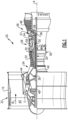
Figure 1 illustrates a gas turbine engine. -
Figure 2 illustrates a second gas turbine engine. -
Figure 1 schematically illustrates agas turbine engine 20. Thegas turbine engine 20 is disclosed herein as a two-spool turbofan that generally incorporates afan section 22, acompressor section 24, a combustor section 26 and aturbine section 28. Thefan section 22 drives air along a bypass flow path B in a bypass duct defined within ahousing 15 such as a fan case or nacelle, and also drives air along a core flow path C for compression and communication into the combustor section 26 then expansion through theturbine section 28. Although depicted as a two-spool turbofan gas turbine engine in the disclosed non-limiting embodiment, it should be understood that the concepts described herein are not limited to use with two-spool turbofans as the teachings may be applied to other types of turbine engines including three-spool architectures. - The
exemplary engine 20 generally includes alow speed spool 30 and ahigh speed spool 32 mounted for rotation about an engine central longitudinal axis A relative to an enginestatic structure 36 viaseveral bearing systems 38. It should be understood that various bearingsystems 38 at various locations may alternatively or additionally be provided, and the location of bearingsystems 38 may be varied as appropriate to the application. - The
low speed spool 30 generally includes aninner shaft 40 that interconnects, a first (or low) pressure compressor 44 and a first (or low)pressure turbine 46. Theinner shaft 40 is connected to thefan 42 through a speed change mechanism, which in exemplarygas turbine engine 20 is illustrated as a gearedarchitecture 48 to drive afan 42 at a lower speed than thelow speed spool 30. Thehigh speed spool 32 includes anouter shaft 50 that interconnects a second (or high)pressure compressor 52 and a second (or high)pressure turbine 54. Acombustor 56 is arranged ingas turbine 20 between thehigh pressure compressor 52 and thehigh pressure turbine 54. Amid-turbine frame 57 of the enginestatic structure 36 may be arranged generally between thehigh pressure turbine 54 and thelow pressure turbine 46. Themid-turbine frame 57 furthersupports bearing systems 38 in theturbine section 28. Theinner shaft 40 and theouter shaft 50 are concentric and rotate via bearingsystems 38 about the engine central longitudinal axis A which is collinear with their longitudinal axes. - The core airflow is compressed by the low pressure compressor 44 then the
high pressure compressor 52, mixed and burned with fuel in thecombustor 56, then expanded through thehigh pressure turbine 54 andlow pressure turbine 46. Themid-turbine frame 57 includesairfoils 59 which are in the core airflow path C. Theturbines low speed spool 30 andhigh speed spool 32 in response to the expansion. It will be appreciated that each of the positions of thefan section 22,compressor section 24, combustor section 26,turbine section 28, and fandrive gear system 48 may be varied. For example,gear system 48 may be located aft of the low pressure compressor, or aft of the combustor section 26 or even aft ofturbine section 28, andfan 42 may be positioned forward or aft of the location ofgear system 48. - The
engine 20 in one example is a high-bypass geared aircraft engine. In a further example, theengine 20 bypass ratio is greater than about six, with an example embodiment being greater than about ten, or greater than thirteen, the gearedarchitecture 48 is an epicyclic gear train, such as a planetary gear system or other gear system, with a gear reduction ratio of greater than about 2.3, or greater and 3.0, and thelow pressure turbine 46 has a pressure ratio that is greater than about five (5:1). In one disclosed embodiment, theengine 20 bypass ratio is greater than about ten (10:1), the fan diameter is significantly larger than that of the low pressure compressor 44, and thelow pressure turbine 46 has a pressure ratio that is greater than about five (5:1).Low pressure turbine 46 pressure ratio is measured as the pressure prior to inlet oflow pressure turbine 46 as related to the pressure at the outlet of thelow pressure turbine 46 prior to an exhaust nozzle. The gearedarchitecture 48 may be an epicycle gear train, such as a planetary gear system or other gear system, with a gear reduction ratio of greater than about 2.3:1 and less than about 5:1. It should be understood, however, that the above parameters are only exemplary of one embodiment of a geared architecture engine and that the present invention is applicable to other gas turbine engines including direct drive turbofans. - A significant amount of thrust is provided by the bypass flow B due to the high bypass ratio. The
fan section 22 of theengine 20 is designed for a particular flight condition -- typically cruise at about 0.8 Mach and about 35,000 feet (10,668 meters). The flight condition of 0.8 Mach and 35,000 ft (10,668 meters), with the engine at its best fuel consumption - also known as "bucket cruise Thrust Specific Fuel Consumption ('TSFC')" - is the industry standard parameter of lbm of fuel being burned divided by lbf of thrust the engine produces at that minimum point. "Low fan pressure ratio" is the pressure ratio across the fan blade alone, without a Fan Exit Guide Vane ("FEGV") system. The low fan pressure ratio as disclosed herein according to one non-limiting embodiment is less than about 1.45. "Low corrected fan tip speed" is the actual fan tip speed in ft/sec divided by an industry standard temperature correction of [(Tram °R) / (518.7 °R)]0.5 (where °R = 9/5 x K) The "Low corrected fan tip speed" as disclosed herein according to one non-limiting embodiment is less than about 1150 ft / second (350.5 meters/second). -
Figure 2 schematically illustrates a gearedengine embodiment 100 wherein agear reduction 102 is positioned between a low pressure turbine orfan drive turbine 104 and alow pressure compressor 106 such that thelow pressure compressor 106 and afan section 108 are driven to rotate together at a lower speed than thelow pressure turbine 104. Thefan section 108 includes afan shaft 110, afan 112 connected to thefan shaft 110, and anouter housing 114 surrounding thefan 112 to define a bypasspassage B. Engine 100 includes alow speed spool 116 and ahigh speed spool 118 mounted for rotation about an engine central longitudinal axis A. Thelow speed spool 116 includes thelow pressure turbine 104 and drives thegear reduction 102 to, in turn, drivefan shaft 110, these rotatably connected components define afan drivetrain 120. Thefan 112 and thelow pressure compressor 106 are fixed to rotate with thefan shaft 110. The connection betweenfan 112 and thelow pressure compressor 106 is shown schematically. In fact, they may be separately secured tofan shaft 110. Thehigh speed spool 118 includes ahigh pressure turbine 122 driving ahigh pressure compressor 124. Acombustor 126 is intermediate thehigh pressure compressor 124 and thehigh pressure turbine 122. The operation, performance quantities, and other details mentioned above with regard toengine 20 also apply toengine 100. -
Low pressure turbine 104 further includesrotating blades 128 and astatic structure 130 at a position aft of therotating blades 128. In one embodiment, thestatic structure 130 includes vanes of thelow pressure turbine 104. - A
thrust bearing 132 is located axially between thelow pressure compressor 106 andhigh pressure compressor 124.Thrust bearing 132 is loaded in an axially aft direction and keeps thelow speed spool 116 axially in place during normal operation. - The
low speed spool 116 may comprise a lowspeed shaft section 134 mounting thelow pressure turbine 104 and aninput shaft section 136 as an input driving thegear reduction 102. Theinput shaft section 136 is located axially forward ofthrust bearing 132. The lowspeed shaft section 134 andinput shaft section 136 may be separate components fixed to rotate together. Alternatively,sections input shaft section 136 may be flexible relative to lowspeed shaft section 134. -
Engine 100 also includes over-speed protection of thelow pressure turbine 104 in the event of acomponent failure 137 in thefan drivetrain 120.Engine 20 includes acontrol 138 andsensors 139. Thesensors 139 detect the occurrence of acomponent failure 137 in thefan drive train 120 and transmit this information to thecontrol 138.Component failure 137 is illustrated as a failure oninput shaft section 136, axially forward ofthrust bearing 132. However, it should be understood thatcomponent failure 137 could occur at any location and component of thefan drivetrain 120, including on thelow speed spool 116, within thegear reduction 102, or on thefan shaft 110.Component failure 137 may be a shearing of the rotating component, but may also include fractures, deflection, buckling, or other mechanical failures causing a decoupling of the component from the drivetrain. - The
control 138 initiates a fuel shut-off procedure when it receives information that anysuch component failure 137 has occurred. As an example,control 138 is shown communicating with afuel pump 200 to achieve the fuel shut-off.Control 138 may be incorporated into a full authority digital engine control (FADEC) or may be a stand-alone control. When the fuel shut-off procedure is executed, fuel delivery to thecombustor 126 is terminated and combustion products cease to expand across and accelerate thelow pressure turbine 104. However, there is some amount of time delay between the occurrence ofcomponent failure 137 and the execution of the fuel shut-off procedure. - Should the
fan drivetrain 120 fail at a location aft ofthrust bearing 132, then the absence of thethrust bearing 132 load will shift therotating blades 128 axially aft to clash with thestatic structure 130, thereby preventing a turbine over-speed condition in the time it takes to execute the fuel shut-off procedure. However, in the event of a failure of thefan drivetrain 120 forward of thethrust bearing 132, thelow pressure turbine 104 will remain axially in place. Accordingly, to provide an over-speed mitigating counter-load onlow pressure turbine 104 in this event, as well as to provide other benefits that will be described below,engine 100 is provided with atower shaft 140 which is rotatably connected to thelow speed spool 116. - Note that in an engine like the one illustrated in
Figure 1 , a failure forward to the low pressure compressor will result in the fan drive turbine having the counter-load of the low pressure compressor to provide over-speed mitigation. This is not the case with theengine 100. - The
tower shaft 140 is connected to thelow speed spool 116 at a location axially aft ofthrust bearing 132 and extends out from thelow speed spool 116 in an at least partially circumferential direction. In one embodiment, thetower shaft 140 is connected to thelow speed spool 116 at a location axially forward of the high-pressure compressor 124. However,tower shaft 140 may also be connected at other locations, such as axially between thehigh pressure compressor 124 and thecombustor 126, between the combustor 126 andhigh pressure turbine 122, between thehigh pressure turbine 122 andlow pressure turbine 104, or axially aft of thelow pressure turbine 104. Thelow speed spool 116 drives thetower shaft 140 to rotate. In the event of a component failure in thefan drivetrain 120 forward ofthrust bearing 132, thetower shaft 140 is configured to provide a counter-load to mitigate thelow pressure turbine 104 reaching an over-speed condition in the time it takes to execute the fuel shut-off procedure. - In one embodiment, the
tower shaft 140 drives anengine accessory component 142. In one embodiment, theengine accessory component 142 is a generator turning the rotation of thetower shaft 140 into electrical energy and delivering this energy to an associated aircraft mounting theengine 100. Theengine accessory component 142 may be any other type of engine accessory providing a sufficient counter-load, such as a fuel pump, a lubricating oil pump delivering lubrication to thegear reduction 102 or elsewhere, a high pressure air compressor for aircraft undercarriage actuation, a low pressure air compressor for aircraft cabin environmental control, or an engine starter. - The
tower shaft 140 may also be connected to abraking mechanism 144 such as a hydraulic or spring-activated clutch. In one embodiment, thecontrol 138 activates thebraking mechanism 144 when a failure in thefan drivetrain 120 is detected. In another embodiment, thecontrol 138 may activate thebraking mechanism 144 if thelow pressure turbine 104 reaches a speed above a predetermined threshold. Thebraking mechanism 144 may be directly connected to thetower shaft 140, or integrated in theengine accessory component 142 driven by thetower shaft 140. Alternatively, abraking mechanism 210 may be mounted directly on thelow speed spool 116. Activation of thebraking mechanism 144 increases the counter-load that thetower shaft 140 applies on thelow speed spool 116 to resist rotation and further slow or stop thelow pressure turbine 104 during a fan drivetrain failure event. The event in this case is loss of torque at any point axially forward of thethrust bearing 132, including theinput shaft section 136, thegear reduction 102, or thefan shaft 110. - The foregoing description is exemplary rather than defined by the limitations within. Various non-limiting embodiments are disclosed herein, however, one of ordinary skill in the art would recognize that various modifications and variations in light of the above teachings will fall within the scope of the appended claims. It is therefore to be understood that within the scope of the appended claims, the disclosure may be practiced other than as specifically described. For that reason, the appended claims should be studied to determine true scope and content.
Claims (13)
- A gas turbine engine (100) comprising:a fan shaft (110) rotatable about an axis (A), a fan (112) connected to said fan shaft (110), and an outer housing (114) surrounding the fan (112) to define a bypass passage (B);a compressor section (24) having both a low pressure compressor (106) that is fixed to rotate with the fan shaft (110) and a high pressure compressor (124);a turbine section (28) having a low pressure turbine (104) driving a low speed spool (116) and a high pressure turbine (122) driving the high pressure compressor (124), the low pressure turbine (104) including rotating blades;a fan drivetrain (120) including a geared architecture (102) connecting the low speed spool (116) to the fan shaft (110) such that the fan (112) and low pressure compressor (106) rotate at a lower speed than the low pressure turbine (104); anda tower shaft (140) rotatably driven by the low speed spool,characterised in that:the gas turbine engine further comprises a thrust bearing (132) axially aft of the geared architecture (102) and axially forward of the high pressure compressor (124); andthe thrust bearing (132) is aft-loaded such that the low pressure turbine blades will shift axially aft in the event of a fan drivetrain (120) failure at a location axially aft of the thrust bearing (132).
- The gas turbine engine (100) of claim 1, wherein the low pressure turbine (104) includes a static structure (130) aft of the rotating blades.
- The gas turbine engine (100) of claim 1 or 2, wherein the thrust bearing (132) maintains the low speed spool (116) axially in place in the event of a fan drivetrain (120) failure at a location axially forward of the thrust bearing (132).
- The gas turbine engine (100) of any preceding claim, wherein the low speed spool (116) includes a low speed shaft section (134) mounting the low pressure turbine (104) and an input shaft section (136) axially forward of the thrust bearing (132) and driving the geared architecture (102), the low speed shaft section (134) and input shaft section (136) comprising separate components fixed to rotate together.
- The gas turbine engine (100) of any preceding claim, wherein the tower shaft (140) provides a counter-load on the low speed spool (116) in the event of a fan drivetrain (120) failure at a location axially forward of the thrust bearing (132).
- The gas turbine engine (100) of any preceding claim, wherein the tower shaft (140) connects to the low pressure spool (116) at a location axially forward of the high pressure compressor (124).
- The gas turbine engine (100) of any preceding claim, wherein the tower shaft (140) drives an engine accessory component (142).
- The gas turbine engine (100) of claim 7, wherein the engine accessory component (142) is a generator which delivers electrical power to an associated aircraft.
- The gas turbine engine (100) of any preceding claim, further comprising at least one sensor (139) for detecting a fan drivetrain (120) failure event and communicating to a control (138).
- The gas turbine engine (100) of claim 9, wherein the control (138) initiates a fuel shutoff procedure if the fan drivetrain (120) failure event is detected.
- The gas turbine engine (100) of claim 9 or 10, wherein the control (138) activates a braking mechanism (144) to resist rotation of the low speed spool (116) if the fan drivetrain (120) failure event is detected.
- The gas turbine engine (100) of claim 11, wherein the braking mechanism (144) is directly connected to the low speed spool (116) or the tower shaft (140).
- The gas turbine engine (100) of claim 11, wherein the braking mechanism (144) is included in an engine accessory component (142) driven by the tower shaft (140).
Priority Applications (1)
| Application Number | Priority Date | Filing Date | Title |
|---|---|---|---|
| EP26160474.8A EP4726198A2 (en) | 2020-07-17 | 2021-07-16 | Geared turbofan with over-speed protection |
Applications Claiming Priority (2)
| Application Number | Priority Date | Filing Date | Title |
|---|---|---|---|
| US16/931,685 US12123373B2 (en) | 2020-07-17 | 2020-07-17 | Geared turbofan with over-speed protection |
| EP21186237.0A EP3940214B1 (en) | 2020-07-17 | 2021-07-16 | Geared turbofan with over-speed protection |
Related Parent Applications (1)
| Application Number | Title | Priority Date | Filing Date |
|---|---|---|---|
| EP21186237.0A Division EP3940214B1 (en) | 2020-07-17 | 2021-07-16 | Geared turbofan with over-speed protection |
Related Child Applications (1)
| Application Number | Title | Priority Date | Filing Date |
|---|---|---|---|
| EP26160474.8A Division EP4726198A2 (en) | 2020-07-17 | 2021-07-16 | Geared turbofan with over-speed protection |
Publications (3)
| Publication Number | Publication Date |
|---|---|
| EP4375494A2 true EP4375494A2 (en) | 2024-05-29 |
| EP4375494A3 EP4375494A3 (en) | 2024-07-31 |
| EP4375494B1 EP4375494B1 (en) | 2026-02-25 |
Family
ID=76958880
Family Applications (3)
| Application Number | Title | Priority Date | Filing Date |
|---|---|---|---|
| EP26160474.8A Pending EP4726198A2 (en) | 2020-07-17 | 2021-07-16 | Geared turbofan with over-speed protection |
| EP24170636.5A Active EP4375494B1 (en) | 2020-07-17 | 2021-07-16 | Geared turbofan with over-speed protection |
| EP21186237.0A Active EP3940214B1 (en) | 2020-07-17 | 2021-07-16 | Geared turbofan with over-speed protection |
Family Applications Before (1)
| Application Number | Title | Priority Date | Filing Date |
|---|---|---|---|
| EP26160474.8A Pending EP4726198A2 (en) | 2020-07-17 | 2021-07-16 | Geared turbofan with over-speed protection |
Family Applications After (1)
| Application Number | Title | Priority Date | Filing Date |
|---|---|---|---|
| EP21186237.0A Active EP3940214B1 (en) | 2020-07-17 | 2021-07-16 | Geared turbofan with over-speed protection |
Country Status (2)
| Country | Link |
|---|---|
| US (1) | US12123373B2 (en) |
| EP (3) | EP4726198A2 (en) |
Families Citing this family (1)
| Publication number | Priority date | Publication date | Assignee | Title |
|---|---|---|---|---|
| KR20240029680A (en) * | 2022-08-26 | 2024-03-06 | 삼성디스플레이 주식회사 | Manufacturing method of display device |
Family Cites Families (13)
| Publication number | Priority date | Publication date | Assignee | Title |
|---|---|---|---|---|
| US3792586A (en) * | 1973-01-22 | 1974-02-19 | Avco Corp | Bearing assembly systems |
| US3830058A (en) * | 1973-02-26 | 1974-08-20 | Avco Corp | Fan engine mounting |
| FR2826052B1 (en) * | 2001-06-19 | 2003-12-19 | Snecma Moteurs | RELIEF DEVICE FOR THE IGNITION OF A SELF-ROTATING TURBO-JET |
| US7997085B2 (en) | 2006-09-27 | 2011-08-16 | General Electric Company | Gas turbine engine assembly and method of assembling same |
| US7966806B2 (en) | 2006-10-31 | 2011-06-28 | General Electric Company | Turbofan engine assembly and method of assembling same |
| US8104289B2 (en) * | 2007-10-09 | 2012-01-31 | United Technologies Corp. | Systems and methods involving multiple torque paths for gas turbine engines |
| US8333554B2 (en) * | 2007-11-14 | 2012-12-18 | United Technologies Corporation | Split gearbox and nacelle arrangement |
| US20130186058A1 (en) * | 2012-01-24 | 2013-07-25 | William G. Sheridan | Geared turbomachine fan and compressor rotation |
| US20160178464A1 (en) * | 2014-12-19 | 2016-06-23 | Rolls-Royce Corporation | Torque sensor monitoring for gas turbine engine |
| US10837312B2 (en) | 2015-02-27 | 2020-11-17 | Pratt & Whitney Canada Corp. | System for braking a low pressure spool in a gas turbine engine |
| US10808624B2 (en) | 2017-02-09 | 2020-10-20 | Pratt & Whitney Canada Corp. | Turbine rotor with low over-speed requirements |
| US10612555B2 (en) | 2017-06-16 | 2020-04-07 | United Technologies Corporation | Geared turbofan with overspeed protection |
| US10718271B2 (en) | 2018-05-29 | 2020-07-21 | Raytheon Technologies Corporation | Hybrid amplification of high spool motoring via low spool power extraction and motoring of a differential geared generator |
-
2020
- 2020-07-17 US US16/931,685 patent/US12123373B2/en active Active
-
2021
- 2021-07-16 EP EP26160474.8A patent/EP4726198A2/en active Pending
- 2021-07-16 EP EP24170636.5A patent/EP4375494B1/en active Active
- 2021-07-16 EP EP21186237.0A patent/EP3940214B1/en active Active
Also Published As
| Publication number | Publication date |
|---|---|
| EP3940214B1 (en) | 2024-04-17 |
| EP4375494A3 (en) | 2024-07-31 |
| EP4375494B1 (en) | 2026-02-25 |
| EP3940214A1 (en) | 2022-01-19 |
| US12123373B2 (en) | 2024-10-22 |
| US20220018311A1 (en) | 2022-01-20 |
| EP4726198A2 (en) | 2026-04-15 |
Similar Documents
| Publication | Publication Date | Title |
|---|---|---|
| EP3415727B1 (en) | Gas turbine engine | |
| EP3228855B1 (en) | Anti-windmilling system and method for a gas turbine engine | |
| US12385413B2 (en) | Geared turbofan with overspeed protection | |
| EP3431738B1 (en) | Tangential drive for gas turbine engine accessories | |
| EP2807358B1 (en) | Geared turbomachine fan and compressor rotation | |
| EP3543483B1 (en) | Windmill lubrication gear train for lubricant system in a geared gas turbine engine | |
| EP2809921B1 (en) | Gas turbine engine with compressor inlet guide vane positioned for starting | |
| EP3584427B1 (en) | Intercooled cooling air with low temperature bearing compartment air | |
| US20180187605A1 (en) | Systems and methods involving multiple torque paths for gas turbine engines | |
| EP2809924B1 (en) | Gas turbine engine with variable area fan nozzle positioned for starting | |
| EP2884056A1 (en) | Systems and methods involving multiple torque paths for gas turbine engines | |
| EP4375494B1 (en) | Geared turbofan with over-speed protection | |
| EP2900978B1 (en) | Compressor section comprising a seal hook mount structure with overlapped coating | |
| EP4001597A1 (en) | Starter turbine providing gas turbine bearing compartment buffer air | |
| EP4215733B1 (en) | Gear train with variable input direction of rotation and constant output direction of rotation | |
| EP3047109A2 (en) | Fan platform with leading edge tab |
Legal Events
| Date | Code | Title | Description |
|---|---|---|---|
| PUAI | Public reference made under article 153(3) epc to a published international application that has entered the european phase |
Free format text: ORIGINAL CODE: 0009012 |
|
| STAA | Information on the status of an ep patent application or granted ep patent |
Free format text: STATUS: THE APPLICATION HAS BEEN PUBLISHED |
|
| AC | Divisional application: reference to earlier application |
Ref document number: 3940214 Country of ref document: EP Kind code of ref document: P |
|
| AK | Designated contracting states |
Kind code of ref document: A2 Designated state(s): AL AT BE BG CH CY CZ DE DK EE ES FI FR GB GR HR HU IE IS IT LI LT LU LV MC MK MT NL NO PL PT RO RS SE SI SK SM TR |
|
| REG | Reference to a national code |
Ref country code: DE Ref legal event code: R079 Free format text: PREVIOUS MAIN CLASS: F02C0003107000 Ipc: F02C0007360000 Ref country code: DE Ref legal event code: R079 Ref document number: 602021049031 Country of ref document: DE Free format text: PREVIOUS MAIN CLASS: F02C0003107000 Ipc: F02C0007360000 |
|
| PUAL | Search report despatched |
Free format text: ORIGINAL CODE: 0009013 |
|
| AK | Designated contracting states |
Kind code of ref document: A3 Designated state(s): AL AT BE BG CH CY CZ DE DK EE ES FI FR GB GR HR HU IE IS IT LI LT LU LV MC MK MT NL NO PL PT RO RS SE SI SK SM TR |
|
| RIC1 | Information provided on ipc code assigned before grant |
Ipc: F02K 3/06 20060101ALI20240625BHEP Ipc: F02C 3/107 20060101ALI20240625BHEP Ipc: F02C 7/36 20060101AFI20240625BHEP |
|
| STAA | Information on the status of an ep patent application or granted ep patent |
Free format text: STATUS: REQUEST FOR EXAMINATION WAS MADE |
|
| 17P | Request for examination filed |
Effective date: 20250131 |
|
| GRAP | Despatch of communication of intention to grant a patent |
Free format text: ORIGINAL CODE: EPIDOSNIGR1 |
|
| STAA | Information on the status of an ep patent application or granted ep patent |
Free format text: STATUS: GRANT OF PATENT IS INTENDED |
|
| INTG | Intention to grant announced |
Effective date: 20250917 |
|
| GRAS | Grant fee paid |
Free format text: ORIGINAL CODE: EPIDOSNIGR3 |
|
| GRAA | (expected) grant |
Free format text: ORIGINAL CODE: 0009210 |
|
| STAA | Information on the status of an ep patent application or granted ep patent |
Free format text: STATUS: THE PATENT HAS BEEN GRANTED |
|
| AC | Divisional application: reference to earlier application |
Ref document number: 3940214 Country of ref document: EP Kind code of ref document: P |
|
| AK | Designated contracting states |
Kind code of ref document: B1 Designated state(s): AL AT BE BG CH CY CZ DE DK EE ES FI FR GB GR HR HU IE IS IT LI LT LU LV MC MK MT NL NO PL PT RO RS SE SI SK SM TR |
|
| REG | Reference to a national code |
Ref country code: CH Ref legal event code: F10 Free format text: ST27 STATUS EVENT CODE: U-0-0-F10-F00 (AS PROVIDED BY THE NATIONAL OFFICE) Effective date: 20260225 Ref country code: GB Ref legal event code: FG4D |
|
| REG | Reference to a national code |
Ref country code: DE Ref legal event code: R096 Ref document number: 602021049031 Country of ref document: DE |
|
| REG | Reference to a national code |
Ref country code: IE Ref legal event code: FG4D |