EP4375430A1 - Construction machine - Google Patents
Construction machine Download PDFInfo
- Publication number
- EP4375430A1 EP4375430A1 EP23780339.0A EP23780339A EP4375430A1 EP 4375430 A1 EP4375430 A1 EP 4375430A1 EP 23780339 A EP23780339 A EP 23780339A EP 4375430 A1 EP4375430 A1 EP 4375430A1
- Authority
- EP
- European Patent Office
- Prior art keywords
- controller
- action
- operation lever
- lever device
- hydraulic actuator
- Prior art date
- Legal status (The legal status is an assumption and is not a legal conclusion. Google has not performed a legal analysis and makes no representation as to the accuracy of the status listed.)
- Pending
Links
Images




Classifications
-
- E—FIXED CONSTRUCTIONS
- E02—HYDRAULIC ENGINEERING; FOUNDATIONS; SOIL SHIFTING
- E02F—DREDGING; SOIL-SHIFTING
- E02F9/00—Component parts of dredgers or soil-shifting machines, not restricted to one of the kinds covered by groups E02F3/00 - E02F7/00
- E02F9/20—Drives; Control devices
- E02F9/22—Hydraulic or pneumatic drives
- E02F9/2203—Arrangements for controlling the attitude of actuators, e.g. speed, floating function
-
- E—FIXED CONSTRUCTIONS
- E02—HYDRAULIC ENGINEERING; FOUNDATIONS; SOIL SHIFTING
- E02F—DREDGING; SOIL-SHIFTING
- E02F9/00—Component parts of dredgers or soil-shifting machines, not restricted to one of the kinds covered by groups E02F3/00 - E02F7/00
- E02F9/20—Drives; Control devices
- E02F9/2004—Control mechanisms, e.g. control levers
-
- E—FIXED CONSTRUCTIONS
- E02—HYDRAULIC ENGINEERING; FOUNDATIONS; SOIL SHIFTING
- E02F—DREDGING; SOIL-SHIFTING
- E02F9/00—Component parts of dredgers or soil-shifting machines, not restricted to one of the kinds covered by groups E02F3/00 - E02F7/00
- E02F9/20—Drives; Control devices
- E02F9/2025—Particular purposes of control systems not otherwise provided for
-
- E—FIXED CONSTRUCTIONS
- E02—HYDRAULIC ENGINEERING; FOUNDATIONS; SOIL SHIFTING
- E02F—DREDGING; SOIL-SHIFTING
- E02F9/00—Component parts of dredgers or soil-shifting machines, not restricted to one of the kinds covered by groups E02F3/00 - E02F7/00
- E02F9/20—Drives; Control devices
- E02F9/2025—Particular purposes of control systems not otherwise provided for
- E02F9/2033—Limiting the movement of frames or implements, e.g. to avoid collision between implements and the cabin
-
- E—FIXED CONSTRUCTIONS
- E02—HYDRAULIC ENGINEERING; FOUNDATIONS; SOIL SHIFTING
- E02F—DREDGING; SOIL-SHIFTING
- E02F9/00—Component parts of dredgers or soil-shifting machines, not restricted to one of the kinds covered by groups E02F3/00 - E02F7/00
- E02F9/20—Drives; Control devices
- E02F9/2058—Electric or electro-mechanical or mechanical control devices of vehicle sub-units
- E02F9/2062—Control of propulsion units
- E02F9/2066—Control of propulsion units of the type combustion engines
-
- E—FIXED CONSTRUCTIONS
- E02—HYDRAULIC ENGINEERING; FOUNDATIONS; SOIL SHIFTING
- E02F—DREDGING; SOIL-SHIFTING
- E02F9/00—Component parts of dredgers or soil-shifting machines, not restricted to one of the kinds covered by groups E02F3/00 - E02F7/00
- E02F9/20—Drives; Control devices
- E02F9/22—Hydraulic or pneumatic drives
- E02F9/2221—Control of flow rate; Load sensing arrangements
- E02F9/2232—Control of flow rate; Load sensing arrangements using one or more variable displacement pumps
- E02F9/2235—Control of flow rate; Load sensing arrangements using one or more variable displacement pumps including an electronic controller
-
- E—FIXED CONSTRUCTIONS
- E02—HYDRAULIC ENGINEERING; FOUNDATIONS; SOIL SHIFTING
- E02F—DREDGING; SOIL-SHIFTING
- E02F9/00—Component parts of dredgers or soil-shifting machines, not restricted to one of the kinds covered by groups E02F3/00 - E02F7/00
- E02F9/20—Drives; Control devices
- E02F9/22—Hydraulic or pneumatic drives
- E02F9/2264—Arrangements or adaptations of elements for hydraulic drives
- E02F9/2271—Actuators and supports therefor and protection therefor
-
- E—FIXED CONSTRUCTIONS
- E02—HYDRAULIC ENGINEERING; FOUNDATIONS; SOIL SHIFTING
- E02F—DREDGING; SOIL-SHIFTING
- E02F9/00—Component parts of dredgers or soil-shifting machines, not restricted to one of the kinds covered by groups E02F3/00 - E02F7/00
- E02F9/20—Drives; Control devices
- E02F9/22—Hydraulic or pneumatic drives
- E02F9/2278—Hydraulic circuits
- E02F9/2296—Systems with a variable displacement pump
-
- E—FIXED CONSTRUCTIONS
- E02—HYDRAULIC ENGINEERING; FOUNDATIONS; SOIL SHIFTING
- E02F—DREDGING; SOIL-SHIFTING
- E02F9/00—Component parts of dredgers or soil-shifting machines, not restricted to one of the kinds covered by groups E02F3/00 - E02F7/00
- E02F9/24—Safety devices, e.g. for preventing overload
-
- E—FIXED CONSTRUCTIONS
- E02—HYDRAULIC ENGINEERING; FOUNDATIONS; SOIL SHIFTING
- E02F—DREDGING; SOIL-SHIFTING
- E02F9/00—Component parts of dredgers or soil-shifting machines, not restricted to one of the kinds covered by groups E02F3/00 - E02F7/00
- E02F9/26—Indicating devices
-
- F—MECHANICAL ENGINEERING; LIGHTING; HEATING; WEAPONS; BLASTING
- F15—FLUID-PRESSURE ACTUATORS; HYDRAULICS OR PNEUMATICS IN GENERAL
- F15B—SYSTEMS ACTING BY MEANS OF FLUIDS IN GENERAL; FLUID-PRESSURE ACTUATORS, e.g. SERVOMOTORS; DETAILS OF FLUID-PRESSURE SYSTEMS, NOT OTHERWISE PROVIDED FOR
- F15B15/00—Fluid-actuated devices for displacing a member from one position to another; Gearing associated therewith
- F15B15/20—Other details, e.g. assembly with regulating devices
- F15B15/204—Control means for piston speed or actuating force without external control, e.g. control valve inside the piston
-
- F—MECHANICAL ENGINEERING; LIGHTING; HEATING; WEAPONS; BLASTING
- F15—FLUID-PRESSURE ACTUATORS; HYDRAULICS OR PNEUMATICS IN GENERAL
- F15B—SYSTEMS ACTING BY MEANS OF FLUIDS IN GENERAL; FLUID-PRESSURE ACTUATORS, e.g. SERVOMOTORS; DETAILS OF FLUID-PRESSURE SYSTEMS, NOT OTHERWISE PROVIDED FOR
- F15B21/00—Common features of fluid actuator systems; Fluid-pressure actuator systems or details thereof, not covered by any other group of this subclass
-
- B—PERFORMING OPERATIONS; TRANSPORTING
- B60—VEHICLES IN GENERAL
- B60Y—INDEXING SCHEME RELATING TO ASPECTS CROSS-CUTTING VEHICLE TECHNOLOGY
- B60Y2200/00—Type of vehicle
- B60Y2200/40—Special vehicles
- B60Y2200/41—Construction vehicles, e.g. graders, excavators
- B60Y2200/412—Excavators
-
- E—FIXED CONSTRUCTIONS
- E02—HYDRAULIC ENGINEERING; FOUNDATIONS; SOIL SHIFTING
- E02F—DREDGING; SOIL-SHIFTING
- E02F9/00—Component parts of dredgers or soil-shifting machines, not restricted to one of the kinds covered by groups E02F3/00 - E02F7/00
- E02F9/20—Drives; Control devices
- E02F9/22—Hydraulic or pneumatic drives
- E02F9/2278—Hydraulic circuits
- E02F9/2285—Pilot-operated systems
-
- E—FIXED CONSTRUCTIONS
- E02—HYDRAULIC ENGINEERING; FOUNDATIONS; SOIL SHIFTING
- E02F—DREDGING; SOIL-SHIFTING
- E02F9/00—Component parts of dredgers or soil-shifting machines, not restricted to one of the kinds covered by groups E02F3/00 - E02F7/00
- E02F9/20—Drives; Control devices
- E02F9/22—Hydraulic or pneumatic drives
- E02F9/2278—Hydraulic circuits
- E02F9/2292—Systems with two or more pumps
-
- F—MECHANICAL ENGINEERING; LIGHTING; HEATING; WEAPONS; BLASTING
- F15—FLUID-PRESSURE ACTUATORS; HYDRAULICS OR PNEUMATICS IN GENERAL
- F15B—SYSTEMS ACTING BY MEANS OF FLUIDS IN GENERAL; FLUID-PRESSURE ACTUATORS, e.g. SERVOMOTORS; DETAILS OF FLUID-PRESSURE SYSTEMS, NOT OTHERWISE PROVIDED FOR
- F15B20/00—Safety arrangements for fluid actuator systems; Applications of safety devices in fluid actuator systems; Emergency measures for fluid actuator systems
-
- F—MECHANICAL ENGINEERING; LIGHTING; HEATING; WEAPONS; BLASTING
- F15—FLUID-PRESSURE ACTUATORS; HYDRAULICS OR PNEUMATICS IN GENERAL
- F15B—SYSTEMS ACTING BY MEANS OF FLUIDS IN GENERAL; FLUID-PRESSURE ACTUATORS, e.g. SERVOMOTORS; DETAILS OF FLUID-PRESSURE SYSTEMS, NOT OTHERWISE PROVIDED FOR
- F15B2211/00—Circuits for servomotor systems
- F15B2211/60—Circuit components or control therefor
- F15B2211/63—Electronic controllers
- F15B2211/6303—Electronic controllers using input signals
- F15B2211/6346—Electronic controllers using input signals representing a state of input means, e.g. joystick position
-
- F—MECHANICAL ENGINEERING; LIGHTING; HEATING; WEAPONS; BLASTING
- F15—FLUID-PRESSURE ACTUATORS; HYDRAULICS OR PNEUMATICS IN GENERAL
- F15B—SYSTEMS ACTING BY MEANS OF FLUIDS IN GENERAL; FLUID-PRESSURE ACTUATORS, e.g. SERVOMOTORS; DETAILS OF FLUID-PRESSURE SYSTEMS, NOT OTHERWISE PROVIDED FOR
- F15B2211/00—Circuits for servomotor systems
- F15B2211/70—Output members, e.g. hydraulic motors or cylinders or control therefor
- F15B2211/71—Multiple output members, e.g. multiple hydraulic motors or cylinders
-
- F—MECHANICAL ENGINEERING; LIGHTING; HEATING; WEAPONS; BLASTING
- F15—FLUID-PRESSURE ACTUATORS; HYDRAULICS OR PNEUMATICS IN GENERAL
- F15B—SYSTEMS ACTING BY MEANS OF FLUIDS IN GENERAL; FLUID-PRESSURE ACTUATORS, e.g. SERVOMOTORS; DETAILS OF FLUID-PRESSURE SYSTEMS, NOT OTHERWISE PROVIDED FOR
- F15B2211/00—Circuits for servomotor systems
- F15B2211/70—Output members, e.g. hydraulic motors or cylinders or control therefor
- F15B2211/75—Control of speed of the output member
-
- F—MECHANICAL ENGINEERING; LIGHTING; HEATING; WEAPONS; BLASTING
- F15—FLUID-PRESSURE ACTUATORS; HYDRAULICS OR PNEUMATICS IN GENERAL
- F15B—SYSTEMS ACTING BY MEANS OF FLUIDS IN GENERAL; FLUID-PRESSURE ACTUATORS, e.g. SERVOMOTORS; DETAILS OF FLUID-PRESSURE SYSTEMS, NOT OTHERWISE PROVIDED FOR
- F15B2211/00—Circuits for servomotor systems
- F15B2211/80—Other types of control related to particular problems or conditions
- F15B2211/85—Control during special operating conditions
- F15B2211/851—Control during special operating conditions during starting
-
- F—MECHANICAL ENGINEERING; LIGHTING; HEATING; WEAPONS; BLASTING
- F15—FLUID-PRESSURE ACTUATORS; HYDRAULICS OR PNEUMATICS IN GENERAL
- F15B—SYSTEMS ACTING BY MEANS OF FLUIDS IN GENERAL; FLUID-PRESSURE ACTUATORS, e.g. SERVOMOTORS; DETAILS OF FLUID-PRESSURE SYSTEMS, NOT OTHERWISE PROVIDED FOR
- F15B2211/00—Circuits for servomotor systems
- F15B2211/80—Other types of control related to particular problems or conditions
- F15B2211/86—Control during or prevention of abnormal conditions
- F15B2211/8643—Control during or prevention of abnormal conditions the abnormal condition being a human failure
Definitions
- the present invention relates to a construction machine such as a hydraulic excavator.
- operation lever devices In a construction machine such as a hydraulic excavator, a plurality of operation lever devices are used to operate individually corresponding actuators.
- the corresponding relationship (hereinafter referred to as operation assignments) between operation lever devices and actuators differs among different manufacturers of construction machines. Therefore, for example, when an operator uses a construction machine of a manufacturer different from that of a construction machine accustomed to use by the operator, there is the possibility that the operator may perform a wrong operation in a case where the operator does not grasp that the operation assignments are different.
- Patent Document 1 a construction machine having a changing function of operation assignments is known in which a selected operation assignment is displayed on a monitor and start of running is permitted on condition that an operator performs a response operation indicating that the displayed operation assignment is confirmed.
- Patent Document 1 JP-2006-144296-A
- Patent Document 1 Even if the technology of Patent Document 1 is applied, if the operator performs a response operation without confirming the operation assignment, then the construction machine is placed into a state in which it can be run while the operator does not grasp the operation assignment, and a wrong operation is not necessarily be suppressed sufficiently.
- the object of the present invention resides in provision of a construction machine that can suppress a wrong operation arising from false recognition of an operation assignment.
- the present invention provides a construction machine including a plurality of hydraulic actuators, a hydraulic pump that discharges pressure fluid for driving the plurality of hydraulic actuators, an engine that drives the hydraulic pump, a plurality of operation lever devices that operate the corresponding hydraulic actuators, a key switch that starts the engine, a speed sensor that detects a rotational speed of the engine, a plurality of operation sensors that sense operation of the corresponding operation lever devices, and a controller that controls, in response to operation of the operation lever devices, action of a corresponding one of the hydraulic actuators, in which the controller is configured to decide, on the basis of signals from the key switch, the speed sensor, and the plurality of operation sensors, whether operation of an operation lever device is first time operation after start of the engine, and limit, in a case where it is decided that the operation of the operation lever device is first time operation after start of the engine, action speed of the hydraulic actuator.
- FIG. 1 is a side elevational view of a hydraulic excavator that is an example of a construction machine according to a first embodiment of the present invention.
- the leftward and rightward direction in the figure is the forward and rearward direction of the hydraulic excavator (accurately, of its swing structure).
- the hydraulic excavator depicted in FIG. 1 includes a track structure 10, a swing structure 20, a front work implement 30, and so forth.
- the track structure 10 includes a pair of left and right crawlers 11 (only one on one side is depicted), crawler frames 12, and so forth.
- the left and right crawlers 11 individually include a travel driving device 13 such that they can act independently of each other.
- the travel driving device is configured from a traveling hydraulic motor, a speed reduction mechanism, and so forth.
- the swing structure 20 is swingably mounted at an upper portion of the track structure 10 and includes a swing frame 21, a swing mechanism 22, a swing motor 23, a cab 24, an engine 25, and so forth.
- the swing frame 21 is swingably coupled around a vertical axis to an upper portion of the crawler frames 12.
- the swing mechanism 22 uses driving force of the swing motor 23 to drive the swing structure 20 (swing frame 21) to swing with respect to the track structure 10.
- the cab 24 is an operation room for being boarded by an operator in order to operate the hydraulic excavator.
- the engine 25 is a prime mover of the hydraulic excavator.
- the cab 24 and the engine 25 are mounted at an upper portion of the swing frame 21.
- the engine 25 includes a speed sensor 47 ( FIG. 3 ) for detecting the engine speed.
- the front work implement 30 is coupled to the swing structure 20 and is configured from a boom 31, a boom cylinder 32, an arm 33, an arm cylinder 34, a bucket 35, a bucket cylinder 36, and so forth.
- the boom 31 is coupled pivotably in the upward and downward direction with respect to the swing frame 21 by a shaft having a center line extending in the leftward and rightward direction.
- the boom cylinder 32 is coupled at the opposite ends thereof to the swing frame 21 and the boom 31 such that it is expanded and contracted to drive the boom 31 upwardly and downwardly.
- the arm 33 is coupled pivotably in the forward and rearward direction to a distal end of the boom 31 by a shaft having a center line extending leftwardly and rightwardly.
- the arm cylinder 34 is coupled at the opposite ends thereof to the boom 31 and the arm 33 such that it is expanded and contracted to drive the arm 33 forwardly and rearwardly.
- the bucket 35 is coupled pivotably to a distal end of the arm 33 by a shaft having a center line extending leftwardly and rightwardly.
- the bucket cylinder 36 is suitably coupled at the opposite ends thereof to the arm 33 and the bucket 35 and is configured to expand and contract to drive the bucket 35.
- the bucket 35 is an attachment and can be exchanged to a different attachment such as a breaker or a grapple.
- a hydraulic system configured from a hydraulic pump 40, a flow rate control valve 42 ( FIG. 2 ), and so forth is mounted.
- the hydraulic pump 40 is a hydraulic source and is configured to discharge pressurized fluid for driving a plurality of hydraulic actuators such as a traveling hydraulic motor, the swing motor 23, the boom cylinder 32, the arm cylinder 34, the bucket 35, and the bucket cylinder 36.
- This hydraulic pump 40 is driven by the engine 25.
- the flow rate control valve 42 is a valve unit configured from a plurality of directional control valves that control flow (direction and flow rate) of pressurized fluid to be supplied to the hydraulic actuators.
- the plurality of directional control valves configuring the flow rate control valve 42 are of the hydraulically driven type driven by pilot pressure that acts upon a pressure receiving chamber.
- the directional control valves are each provided in a corresponding relationship to each one of the hydraulic actuators of a driving target.
- left and right operation lever devices 26 and 27 ( FIG. 2 ) are arranged.
- the operation lever devices 26 and 27 are of the cross operation type and individually include a first operation lever device operated so as to be tilted forwardly and rearwardly and a second operation lever device operated so as to be tilted leftwardly and rightwardly such that an operation lever is used in common by the first operation lever device and the second operation lever device.
- the operation lever devices 26 and 27 are arranged on the left and right of a driver's seat in the inside of the cab 24.
- the operation lever devices 26 and 27 operate the hydraulic actuators (the swing motor 23, the boom cylinder 32, the arm cylinder 34, and the bucket cylinder 36).
- a key switch 29 for switching a power supply to the hydraulic excavator between on and off and starting the engine 25
- a gate lock lever (not depicted), and a monitor 70 ( FIG. 3 ) are arranged.
- the gate lock ever is a lever for operating a lock lever device that invalidates operation of the hydraulic actuators performed by the operation lever devices 26 and 27.
- the gate lock lever is installed on the getting on/off side of the driver's seat and is configured such that, when it is placed in a laid down state, it disturbs the operator from getting off, and, when it is raised to open the boarding gate for the driver's seat, it allows the operator to get off.
- FIG. 2 is a circuit diagram depicting essential part of the hydraulic system provided in the construction machine according to the first embodiment of the present invention.
- the operation lever devices 26 and 27 are of the electric type. Operation (operation direction and operation amount) of each of the operation lever devices 26 and 27 is detected by a plurality of operation sensors 28a to 28d and is outputted to a controller 60.
- a sensor that detects a tilt direction and a tilt amount of the operation lever such as a rotary encoder or a potentiometer can be adopted.
- the operation sensor 28a detects operation in the forward and rearward direction of the operation lever device 26, and the operation sensor 28b detects operation in the leftward and rightward direction of the operation lever device 26.
- the operation sensor 28c detects operation in the forward and rearward direction of the operation lever device 27, and the operation sensor 28d detects operation in the leftward and rightward direction of the operation lever device 27.
- the controller 60 outputs a command signal to each of solenoids of solenoid proportional valves (pressure reducing valves) 43a to 43h in response to a lever operation by an operator on the basis of signals from the operation sensors 28a to 28d.
- the solenoid proportional valves 43a to 43h are provided on a pilot line 44 that connects a pilot pump 41 and pressure receiving chambers of the directional control valves of the flow rate control valve 42 (at branch portions connecting to the pressure receiving chambers).
- Each of the solenoid proportional valves 43a to 43h reduces the pressure of pressurized fluid discharged from the pilot pump 41 to generate pilot pressure such that the generated pilot pressure acts upon the pressure receiving chambers of the corresponding directional control valves to drive the directional control valves in a direction according to the operation.
- the solenoid proportional valves 43a and 43b are connected to the corresponding pressure receiving chambers of the directional control valve for the swing motor 23. If pilot pressure is outputted from the solenoid proportional valve 43a, then the spool of the directional control valve for the swing motor 23 is moved to one side, whereupon pressurized fluid from the hydraulic pump 40 is supplied to a port on one side of the swing motor 23 to cause the swing motor 23 to rotate forwardly, and thus a rightward swing action is performed.
- pilot pressure is outputted from the solenoid proportional valve 43b, then the spool of the directional control valve for the swing motor 23 is moved to the other side, whereupon pressurized fluid from the hydraulic pump 40 is supplied to the port on the other side of the swing motor 23 to cause the swing motor 23 to rotate reversely, and thus a leftward swing action is performed.
- the solenoid proportional valves 43c and 43d are connected to the corresponding pressure receiving chambers of the directional control valve for the arm cylinder 34. If pilot pressure is outputted from the solenoid proportional valve 43c, then the spool of the directional control valve for the arm cylinder 34 is moved to one side, whereupon pressurized fluid from the hydraulic pump 40 is supplied to a port on one side of the arm cylinder 34 to cause the arm cylinder 34 to contract, and thus an arm dumping action is performed.
- pilot pressure is outputted from the solenoid proportional valve 43d, then the spool of the directional control valve for the arm cylinder 34 is moved to the other side, whereupon pressurized fluid from the hydraulic pump 40 is supplied to the port on the other side of the arm cylinder 34 to cause the arm cylinder 34 to extend, and thus an arm crowding action is performed.
- the solenoid proportional valves 43e and 43f are connected to the corresponding pressure receiving chambers of the directional control valve for the boom cylinder 32. If pilot pressure is outputted from the solenoid proportional valve 43e, then the spool of the directional control valve for the boom cylinder 32 is moved to one side, whereupon pressurized fluid from the hydraulic pump 40 is supplied to the port on one side of the boom cylinder 32 to cause the boom cylinder 32 to contract, and thus a boom lowering action is performed.
- pilot pressure is outputted from the solenoid proportional valve 43f, then the spool of the directional control valve for the boom cylinder 32 is moved to the other side, whereupon pressurized fluid from the hydraulic pump 40 is supplied to the port on the other side of the boom cylinder 32 to cause the boom cylinder 32 to extend, and thus a boom raising action is performed.
- the solenoid proportional valves 43g and 43h are connected to the corresponding pressure receiving chambers of the directional control valve for the bucket cylinder 36. If pilot pressure is outputted from the solenoid proportional valve 43g, then the spool of the directional control valve for the bucket cylinder 36 is moved to one side, whereupon pressurized fluid from the hydraulic pump 40 is supplied to a port on one side of the bucket cylinder 36 to cause the bucket cylinder 36 to extend, and thus a bucket crowding action is performed.
- pilot pressure is outputted from the solenoid proportional valve 43h, then the spool of the directional control valve for the bucket cylinder 36 is moved to the other side, whereupon pressurized fluid from the hydraulic pump 40 is supplied to the port on the other side of the bucket cylinder 36 to cause the bucket cylinder 36 to contract, and thus a bucket dumping action is performed.
- a lock valve 46 is provided between the solenoid proportional valves 43a to 43h and the pilot pump 41.
- a configuration in which an on-off valve of the electromagnetically driven type is adopted for the lock valve 46 is exemplified.
- the lock valve 46 configures the lock lever device described hereinabove together with the gate lock lever and the position sensor 45 for the gate lock lever ( FIG. 3 ) and is opened and closed by a command signal outputted from the controller 60 in response to the position of the gate lock lever detected by the position sensor 45.
- the controller 60 closes the lock valve 46 in a case where it decides that the gate lock lever is in a raised state on the basis of the position sensor 45. Consequently, supply of pressurized fluid from the pilot pump 41 to the solenoid proportional valves 43a to 43h is cut off, and operation of the hydraulic actuator by the operation lever devices 26 and 27 is invalidated (locked). In this case, the hydraulic actuator is disabled irrespective of whether or not there is operation of the operation lever devices 26 and 27.
- the controller 60 decides that the gate lock lever is in a laid down state on the basis of the position sensor 45, then it opens the lock valve 46. Consequently, pressurized fluid flows from the pilot pump 41 to the solenoid proportional valves 43a to 43h to thereby establish a state in which the solenoid proportional valves 43a to 43h can output pilot pressure. Consequently, operation of the hydraulic actuators by the operation lever devices 26 and 27 is validated (unlocked), and in response to operation of the operation lever device 26 and 27, the hydraulic actuators corresponding with them act.
- FIG. 3 is a functional block diagram of the controller.
- the controller 60 is a machine-carried computer mounted on the hydraulic excavator and includes a memory 61 and a CPU 62.
- the memory 61 is a storage device such as a RAM, a ROM, an HHD and an SSD that store a program and various data necessary for control of target equipment, temporary data during computation operation, and so forth.
- the CPU 62 is a processor that executes various computations, control of target equipment, and so forth on the basis of the program and the various data stored in the memory 61.
- the operation assignment data 63 is data of assignments (operation assignments) of operation of the operation lever devices 26 and 27 to actions of the hydraulic actuators (swing motor 23, boom cylinder 32, arm cylinder 34, and bucket cylinder 36).
- An example of the operation assignment data 63 is described. For example, if the operation lever of the left operation lever device 26 is laid down forwardly, then the swing motor 23 is rotated forwardly, and thus a right swing action is performed, but if the operation lever of the left operation lever device 26 is laid down rearwardly, then the swing motor 23 is rotated reversely, and thus a left swing action is performed. In addition, if the operation lever of the left operation lever device 26 is laid down leftwardly, then the arm cylinder 34 is contracted, and thus an arm dumping action is performed, but if the operation lever of the left operation lever device 26 is laid down rightwardly, then the arm cylinder 34 is extended, and thus an arm crowding action is performed.
- the memory 61 also has limitation target data 64 storable therein.
- the limitation target data 64 is data that defines, in regard to limitation (action limitation 66 hereinafter described) of an action speed of a hydraulic actuator, a target hydraulic actuator and an action direction of the target hydraulic actuator that become a limitation target.
- This limitation target data 64 is configured such that a target hydraulic actuator and an action direction of the target hydraulic actuator, such as forward rotation and reverse rotation (rightward swing and leftward swing) of the swing motor 23 or contraction (arm dumping) of the arm cylinder 34, can be optionally selected and set while the degree of influence of a wrong operation being considered, for example.
- the limitation target data 64 can be made subject to rewriting, deletion, addition, or the like through an inputting terminal T connected to the controller 60. Also for the operation assignment data 63, rewriting, deletion, addition, or the like is performed through the inputting terminal T connected to the controller 60. However, operation for selecting one of the plurality of operation assignment data 63 stored in the memory 61 can be performed by an operator or the like through an inputting device (for example, the monitor 70) installed in the cab 24.
- an inputting device for example, the monitor 70
- the CPU 62 executes functions of output computation 65, action limitation 66, and so forth in accordance with a program stored in the memory 61.
- the output computation 65 is a function for driving, in response to operation of the operation lever devices 26 and 27, corresponding hydraulic actuators. As described hereinabove, signals according to operation of the operation lever devices 26 and 27 are inputted from the operation sensors 28a to 28d to the controller 60.
- the CPU 62 computes, by the function of the output computation 65, command signals (current values) according to the signals from the operation sensors 28a to 28d, and outputs the command signals to the corresponding solenoid proportional valves 43a to 43h.
- the corresponding relationship between the operation direction of the operation lever device 26, 27 and the output destination (solenoid proportional valve 43a to 43h) of the command signal generated in response to the operation depends upon the operation assignment data 63 selected currently.
- the action limitation 66 is a function for limiting, in a case where the operation lever device 26, 27 is operated, the action speed of the hydraulic actuator, which action speed depends on the operation of the operation lever device 26, 27, under a fixed condition.
- the CPU 62 decides, in a case where the operation lever device 26, 27 is operated, whether or not the operation is first time operation after start of the engine 25, and limits, if the operation is first time operation after start of the engine 25, the action speed of the hydraulic actuator, which action speed depends on the operation of the operation lever device 26, 27.
- the CPU 62 decides, on the basis of signals from the key switch 29, speed sensor 47, and operation sensors 28a to 28d, whether the operation of the operation lever device 26 , 27 is first time operation after start of the engine 25.
- the limitation of the action speed is performed by a method in which a preset limit value (upper limit value) to the action speed (for example, command signals to the solenoid proportional valves 43a to 43h) is set and the hydraulic actuator does not act at a speed exceeding the limit value.
- a preset limit value upper limit value
- the hydraulic actuator acts at a speed according to the operation if the operation is a small amount operation of a predetermined operation amount or less, even if operation exceeding the predetermined operation amount is performed, the hydraulic actuator acts only with the limit value (very low moving speed).
- the CPU 62 decides whether or not the operation of the operation lever device is first time operation (operation performed for the first time) performed after an invalidation state is cancelled after the invalidation state of operation of a hydraulic actuator by a lock lever device has continued exceeding a preset time period. Further, the CPU 62 decides whether or not a no-operation state of the operation lever device 26, 27 (neutral state of the operation device without being tilted) has continued for more than the preset time period.
- the CPU 62 limits the action speed of the hydraulic actuator, which action speed depends on the operation of the operation lever device.
- the method for limitation of the action speed of the hydraulic actuator in such cases as described above is similar to that in a case of first time operation after start of the engine 25.
- the limitation target data 64 is stored in the memory 61 as described hereinabove, and the CPU 62 executes the action limitation 66 only in a case where operation corresponding to the action registered in the limitation target data 64 is performed.
- the action limitation 66 executed at the time of first time operation after start of the engine in a case where a target hydraulic actuator set in the limitation target data 64 is operated for the first time after start of the engine, the action speed of the target hydraulic actuator is limited.
- the action limitation 66 that is executed at the time of first time operation performed after an operation invalidation state has continued or executed at the time of operation performed while a no-operation state has continued. If bidirectional actions of all of the swing motor 23, boom cylinder 32, arm cylinder 34, and bucket cylinder 36 are registered in the limitation target data 64, then the function of the action limitation 66 can be applied uniformly to all operation of the operation lever devices 26 and 27.
- the CPU 62 outputs, during limitation of the action speed of a hydraulic actuator, information about the action speed of the hydraulic actuator being limited to the monitor 70 so as to be displayed to thereby notify an operator that the function of the action limitation 66 is being executed.
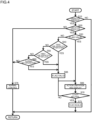
- FIG. 4 is a flow chart depicting a process for action command to a hydraulic actuator by the controller 60.
- the controller 60 repetitively executes the flow of FIG. 4 while it is energized.
- the controller 60 decides first in step S10 whether operation by the operation lever device 26, 27 is being performed on the basis of signals of the operation sensors 28a to 28d. Whether operation is being performed is decided depending upon whether operation exceeding a preset operation amount set in advance is performed (for example, operation exceeding a dead zone). The setting of the preset operation amount is adjusted to prevent such wrong decision that, although an intentional operation is not performed, operation is being performed because of fluctuation of the operation decision value that is caused by vibration of the hydraulic excavator, an electric disturbance, or the like.
- controller 60 decides that none of the operation lever devices 26 and 27 are being operated, it returns the process to step S10 and repeats the process in step S10 until at least one of the operation lever devices 26 and 27 is operated. In a case where the controller 60 decides that at least one of the operation lever devices 26 and 27 is being operated in at least one of the forward, rearward, leftward, and rightward directions, the controller 60 advances the process from step S10 to step S20.
- the controller 60 decides whether the operation being currently performed (in a case where a plurality of different operation are being performed, any one of the operation) is a limitation operation. Whether the operation is a limitation operation is decided depending upon whether the operation is assigned to an action registered in the limitation target data 64 under the operation assignment data 63 currently selected. For example, in a case where a boom raising action is registered as the limitation target data 64, the decision in step S20 is satisfied when there is a boom raising action (in the example described above, a rearwardly tilting operation of the operation lever device 27) in the operation assignment data 63 currently selected.
- step S20 In a case where the operation being currently performed is not a limitation operation, the controller 60 advances the process from step S20 to step S76, but in a case where the operation being currently performed is a limitation operation, the controller 60 advances the process from step S20 to step S30.
- the controller 60 decides whether an action limitation flag is on (valid).
- the action limitation flag is a prerequisite for execution of the function of the action limitation 66, and only in a case where the action limitation flag is on, the function of the action limitation 66 is executed.
- the controller 60 advances the process from step S30 to step S66, but in a case where the action limitation flag is off, the controller 60 advances the process from step S30 to step S40.
- the controller 60 decides, on the basis of signals of the operation sensors 28a to 28d, key switch 29, and speed sensor 47, whether the operation being currently performed is first time operation after start of the engine.
- An algorithm for deciding whether the operation is first time operation after start of the engine in step S40 is hereinafter described with reference to FIG. 5 .
- the controller 60 advances the process from step S40 to step S65, but in a case where the operation being currently performed is not first time operation, the controller 60 advances the process from step S40 to step S50.
- the controller 60 decides, on the basis of a signal of the position sensor 45, whether the operation being currently performed (limitation operation) is first time operation performed after an invalidation state of operation of the hydraulic actuator by the lock lever device has continued exceeding a preset time period.
- the preset time period is a value set in advance and stored in the memory 61 and is a value of, for example, one minute, five minutes, or the like. This preset time period can be made changeable by an operator through an inputting device (for example, the monitor 70) installed in the cab 24.
- the controller 60 advances the process from step S50 to step S65.
- the controller 60 advances the process from step S50 to step S60.
- the controller 60 decides whether or not a no-operation state of the operation lever device 26, 27 has continued exceeding a preset time period.
- the preset time period to be used in this decision is a numerical value such as a value (for example, one minute or five minutes) set in advance and stored in the memory 61, and may be a value equal to that of the preset time period to be used for the decision in step S50 or may be a different value. Also this preset time period can be made changeable by an operator through the inputting device (for example, the monitor 70) installed in the cab 24.
- step S60 If the operation being currently performed is not first time operation after the no-operation state has continued exceeding the preset time interval, then the controller 60 advances the process from step S60 to step S76. If the operation being currently performed is first time operation after the no-operation state has continued exceeding the preset time interval, then the controller 60 advances the process from step S60 to step S65.
- the controller 60 sets the action limitation flag to on (valid) and advances the process to step S66. In particular, even if the action limitation flag is off (invalid) at the point of time of step S30, if the decision in any one of steps S40, S50, and S60 is satisfied, then the action limitation flag is set to on (validated).
- step S66 that is, in a case where a limitation operation is performed and besides the action limitation flag is on
- the controller 60 executes the function of the action limitation 66 described hereinabove and controls the monitor 70 to display that the action limitation operation is being executed. Consequently, even if the operation being currently performed (limitation function) is operation exceeding the predetermined operation amount, the corresponding hydraulic actuator acts not at a speed according to the operation amount but at a limited lower speed.
- the controller 60 decides, on the basis of signals of the operation sensors 28a to 28d, whether the operation lever being currently operated (in a case where both of the operation lever devices 26 and 27 are being operated, both operation levers) has returned to the neutral position. Whether the operation lever has returned to the neutral position is decided depending upon whether the operation amount has returned to the operation amount having been used in the decision in step S10 and equal to or lower than the preset operation amount. While the current operation continues, the controller 60 repetitively executes step S66 to continue the execution of the function of the action limitation 66. If the operation lever being currently operated returns to the neutral position, then the controller 60 stops the execution of the function of the action limitation 66 and the displaying output about this on the monitor 70, and advances the process from step S70 to S75.
- step S75 the controller 60 sets the action limitation flag to off (invalid) and advances the process to step S76 to return the process to step S10.
- step S76 the controller 60 controls, in response to operation of the operation lever device 26, 27, a corresponding hydraulic actuator without executing the function of the action limitation 66.
- the controller 60 decides whether the operation lever being currently performed returns to its neutral position in a similar manner as in step S70, and returns the process to step S10 if the operation lever being currently operated returns to the neutral position. Accordingly, except a situation where the decision in any one of steps S40, S50, and S60 is satisfied and the action limitation flag is changed to on, the process is advanced to step S76 and normal control is executed in a case where the operation lever device 26, 27 is operated.
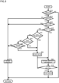
- FIG. 5 is a flow chart depicting a process for post engine start first time operation decision by the controller 60.
- the controller 60 repetitively executes the flow of FIG. 5 , while it is energized, in parallel to the flow of the action command described with reference to FIG. 4 to discriminate whether the operation being currently performed is first time operation after start of the engine.
- the decision in step S40 described with reference to FIG. 4 is performed on the basis of the discrimination by the flow of FIG. 5 .
- the controller 60 first decides in step S80 whether an engine stop flat is on (valid).
- the engine stop flag is a flag that is set to on in a case where it is decided in step S81 that the engine speed is 0, that is, that the engine 25 is in a stopping state.
- the controller 60 advances the process from step S80 to step S83, but in a case where the engine stop flag is off, the controller 60 advances the process from step S80 to step S81.
- step S81 the controller 60 decides on the basis of a signal of the speed sensor 47 whether the engine speed is 0, that is, whether the engine 25 is in a stopping state. In a case where the controller 60 decides that the engine speed is higher than 0 and the engine is operating, the controller 60 ends the current cycle of the process of FIG. 5 and advances the process to step S80 of a next cycle. In a case where the controller 60 decides that the engine speed is 0 and the engine is in a stopping state, the controller 60 advances the process from step S81 to step S82.
- step S82 the controller 60 sets the engine stop flag to on and stores the setting into the memory 61, and advances the process to step S83.
- the controller 60 decides on the basis of a signal of the key switch 29 whether the key switch 29 is at a START position.
- the START position of the key switch 29 is a position for performing cranking at the time of start of the engine and can be used for decision of whether operation for start of the engine is being performed.
- the controller 60 ends the current cycle of the process of FIG. 5 and advances the process to step S80 of a next cycle.
- the controller 60 advances the process from step S83 to step S84.
- the controller 60 decides on the basis of a signal of the speed sensor 47 whether the engine 25 has been started. Whether the engine 25 has been started can be decided depending upon whether the engine speed detected by the speed sensor 47 has reached a preset engine speed set in advance or more. As an example, at the time where the cranking rotational speed by a starter motor has exceeded the engine speed, it can be decided that the engine 25 has been started. In a case where the engine 25 does not start as yet, the controller 60 ends the current cycle of the process of FIG. 5 and advances the process to step S80 of a next cycle. In a case where the engine 25 has been started, the controller 60 advances the process from step S84 to step S85.
- step S85 the controller 60 sets the engine stop flag to off (invalid) and stores the setting into the memory 61, and advances the process to step S86.
- step S86 the controller 60 sets the post engine start first time flag to on (valid) and stores the setting into the memory 61, and advances the process to step S87.
- step S87 the controller 60 decides on the basis of signals of the operation sensors 28a to 28d whether operation by the operation lever device 26, 27 (limitation operation) is being performed. This decision is executed, for example, in a similar way as in the decision in steps S10 and S20 of FIG. 4 . If the operation is not being performed, then the controller 60 repetitively executes the process in step S87 until operation is performed. In a case where operation is performed, the controller 60 advances the process from step S87 to step S88.
- step S88 the controller 60 decides on the basis of signals of the operation sensors 28a to 28d whether the operation lever of the operation lever device 26, 27 being currently operated has been returned to the neutral position. This decision is executed, for example, in a similar manner as in the decision in step S70 of FIG. 4 . If the operation lever being currently operated has not been returned to the neutral position, then the controller 60 repetitively executes the process in step S88 until the operation lever returns to the neutral position. If the operation lever being currently operated returns to the neutral position, then the controller 60 advances the process from step S88 to step S89.
- the controller 60 sets the post engine start first time flag to off (invalid) and stores the setting into the memory 61, and ends the current cycle of the process of FIG. 5 and advances the process to step S80 of a next cycle.
- step S40 of FIG. 4 is satisfied when the post engine start first time flag is on (valid), that is, in a case where an opportunity comes while the processes from step S86 to step S89 of FIG. 5 are executed.
- the post engine start first time flag is off (invalid)
- the decision in step S40 is not satisfied.
- the selection setting function of the limitation target data 64 is not always necessary and can be omitted.
- the action speed of the hydraulic actuator is limited. This makes it possible to effectively suppress also a wrong operation at the time of re-operation after temporary absence of the operator or at the time of change of the operator.
- FIG. 6 is a functional block diagram of a controller provided in a construction machine according to a second embodiment of the present invention.
- like or corresponding elements to those in the first embodiment are denoted by the same reference characters as those in the drawings described hereinabove and description of them is omitted.
- the difference of the present embodiment from the first embodiment resides in that, also in a situation in which the function of the action limitation 66 is executed in the first embodiment (in a case where the decision in step S40 to S60 is satisfied), if the operation being currently performed is moderate operation, then the action limitation 66 is not applied.
- the controller 60 additionally has sudden operation decision 67 as a function to be executed by the CPU 62, and by the sudden operation decision 67, it is decided whether the operation is sudden operation.
- the controller 60 decides on the basis of signals from the operation sensors 28a to 28d whether the increase rate of the operation amount of the operation lever device 26, 27 is greater than a preset increase rate.
- the operation whose increase rate is decided by the sudden operation decision 67 is operation regarding a target hydraulic actuator set in the limitation target data 64.
- the preset increase rate is set in advance and stored in the memory 61. Only in a case where the increase rate of the operation of the operation lever device 26, 27 is higher than the preset increase rate, the controller 60 determines the operation as an execution target of the function of the action limitation 66, and limits the action speed of the hydraulic actuator only in a case where the decision in step S40 to S60 is satisfied.
- FIG. 7 is a schematic view illustrating sudden operation decision.
- FIG. 8 is a schematic view illustrating action limitation in the present embodiment.
- the action limitation 66 is applied in a case where any one of the decision in steps 40 to S60 ( FIG. 4 ) is satisfied.
- the command signal to a solenoid proportional valve is limited at a point of time at which the operation amount reaches the preset value, and even if the operation amount increases exceeding the preset value, the command signal to the solenoid proportional valve does not increase from the limit value.
- the action limitation 66 is not applied and a command signal according to the operation amount is outputted even in a case where one of the decision in steps S40 to S60 ( FIG. 4 ) is satisfied.
- the operation amount reaches the preset value with an increase rate lower than the preset increase rate, if the operation amount increases as it is exceeding the preset value, the command signal to the solenoid proportional valve increases exceeding the limit value.
- the preset increase rate taking into consideration also a response time period until the hydraulic actuator actually begins to act in response to a lever operation.
- the responsiveness of the solenoid proportional valves 43a to 43h, and the responsiveness of the hydraulic actuator depending upon the model, vehicle class, and individual difference of the construction machine it is preferable to use such a configuration that the preset increase rate can be set by an operator or the like through an inputting device (for example, the monitor 70).
- the responsiveness of the hydraulic actuator is influenced much also by the temperature of hydraulic working fluid. Therefore, also such a configuration is preferable that the temperature of hydraulic working fluid measured by a temperature sensor is inputted to the controller 60 and the controller 60 corrects the preset increase rate in response to the temperature of hydraulic working fluid in accordance with an algorithm set in advance.
- FIG. 9 is a flow chart depicting a process for action command of a hydraulic actuator by the controller of the present embodiment.
- the controller 60 repetitively executes the flow of FIG. 9 during energization thereof.
- FIG. 9 corresponds to FIG. 4 of the first embodiment, and in the flow of FIG. 9 , processes same as or corresponding to those of the flow of FIG. 4 are denoted by the same reference characters and description of them is omitted herein.
- the difference of the flow of FIG. 9 from the flow of FIG. 4 resides in that a step S15 for deciding sudden operation is interposed between the step S10 and the step S20, and the other processes are similar to those in the flow of FIG. 9 and the flow of FIG. 4 .
- step S10 the controller 60 advances the process from step S10 to step S15, in which it decides whether the operation is sudden operation as described hereinabove with reference to FIG. 7 . If the operation is moderate operation, then the controller 60 advances the process from step S15 to step S76 without performing decision in steps S30 to S60, and executes normal control of the hydraulic actuator according to the operation in step S76. If the operation is sudden operation, then the controller 60 advances the process from step S15 to step S30 to execute decision in steps S30 to S60 similarly as in the first embodiment. Then, if one of such decision is satisfied, then the controller 60 executes the function of the action limitation 66.
- the function of the action limitation 66 is executed, and advantageous effects similar to those by the first embodiment are obtained.
- the operation is exceptionally excluded from an execution target of the function of the action limitation 66 to omit execution of the function of the action limitation 66.
- the operator who begins to perform operation carefully by a fine operation, even if the operator does not correctly recognize the operation assignment, there is a tendency that the operator naturally attempts conformation of the operation assignment with a fine operation. To such an operator as just described, it is sometimes cumbersome if the function of the action limitation 66 is executed uniformly based on the decision in step S40 to S60.
- the operation is a fine operation
- this is excluded from an execution target of the action limitation 66, and only operation that involves an increase rate equal to or higher than a fixed level is made an execution target of the action limitation 66, then the action limitation 66 is eliminated from being applied to a fine operation. Consequently, regarding an operator who is particularly careful for operation, cumbersomeness or incompatibility by application of the action limitation 66 can be moderated.
- the present invention can be applied also to a construction machine that adopts an operation lever device of the hydraulic type in which a pilot valve is operated by an operation lever.
- a hydraulic operation device is available in which the operation assignment can be switched by a selector valve.
- a potentiometer that senses a lever operation amount or a pressure gauge that senses a pilot pressure is used as the operation sensor, then it is possible to decide whether or not execution of the action limitation 66 is permissible similarly to that in the foregoing description.
- a pressure reducing valve is provided in the pilot line 44 to reduce the pressurized fluid (original pressure) to be supplied to the pilot valve, then it is possible to apply limitation to the pilot pressure.
- the present invention can be applied also to a construction machine that does not have a switching function of an operation assignment. This is because, even with a construction machine in which the operation assignment cannot be switched, for example, at the time when an operator gets on the construction machine first time, the operator may possibly falsely recognize the operation assignment.
- the present invention can be applied also to a construction machine that adopts a mechanical lock valve linked mechanically to a gate lock lever. Also in this case, if the position of the gate lock lever is sensed by the position sensor 45 and inputted to the controller 60, then it is possible to execute the decision in step S50 ( FIG. 4 ).
- a limit value is provided to command signals to the solenoid proportional valves 43a to 43h is described as an execution mode of the action limitation 66
- a different mode such as a mode in which a command signal computed in response to an operation amount is multiplied by a coefficient lower than 1 (for example, of approximately 0.1) to reduce the action speed can be adopted appropriately.
- prime mover is described taking an engine as an example, the prime mover is not limited to an engine, and an electric motor, a fuel cell, or the like may be used as the prime mover. Further, also a combination of them may be used as the prime mover.
Landscapes
- Engineering & Computer Science (AREA)
- General Engineering & Computer Science (AREA)
- Mining & Mineral Resources (AREA)
- Civil Engineering (AREA)
- Structural Engineering (AREA)
- Fluid Mechanics (AREA)
- Physics & Mathematics (AREA)
- Mechanical Engineering (AREA)
- Chemical & Material Sciences (AREA)
- Analytical Chemistry (AREA)
- Operation Control Of Excavators (AREA)
- Component Parts Of Construction Machinery (AREA)
- Fluid-Pressure Circuits (AREA)
Abstract
Description
- The present invention relates to a construction machine such as a hydraulic excavator.
- In a construction machine such as a hydraulic excavator, a plurality of operation lever devices are used to operate individually corresponding actuators. The corresponding relationship (hereinafter referred to as operation assignments) between operation lever devices and actuators differs among different manufacturers of construction machines. Therefore, for example, when an operator uses a construction machine of a manufacturer different from that of a construction machine accustomed to use by the operator, there is the possibility that the operator may perform a wrong operation in a case where the operator does not grasp that the operation assignments are different.
- Meanwhile, a construction machine having a changing function of operation assignments is known in which a selected operation assignment is displayed on a monitor and start of running is permitted on condition that an operator performs a response operation indicating that the displayed operation assignment is confirmed (Patent Document 1).
- Patent Document 1:
JP-2006-144296-A - However, even if the technology of Patent Document 1 is applied, if the operator performs a response operation without confirming the operation assignment, then the construction machine is placed into a state in which it can be run while the operator does not grasp the operation assignment, and a wrong operation is not necessarily be suppressed sufficiently.
- The object of the present invention resides in provision of a construction machine that can suppress a wrong operation arising from false recognition of an operation assignment.
- In order to achieve the object described above, the present invention provides a construction machine including a plurality of hydraulic actuators, a hydraulic pump that discharges pressure fluid for driving the plurality of hydraulic actuators, an engine that drives the hydraulic pump, a plurality of operation lever devices that operate the corresponding hydraulic actuators, a key switch that starts the engine, a speed sensor that detects a rotational speed of the engine, a plurality of operation sensors that sense operation of the corresponding operation lever devices, and a controller that controls, in response to operation of the operation lever devices, action of a corresponding one of the hydraulic actuators, in which the controller is configured to decide, on the basis of signals from the key switch, the speed sensor, and the plurality of operation sensors, whether operation of an operation lever device is first time operation after start of the engine, and limit, in a case where it is decided that the operation of the operation lever device is first time operation after start of the engine, action speed of the hydraulic actuator.
- With the present invention, a false operation by wrong recognition of an allocation assignment can be suppressed.
-
-
FIG. 1 is a side elevational view of a hydraulic excavator that is an example of a construction machine according to a first embodiment of the present invention. -
FIG. 2 is a circuit diagram depicting essential part of a hydraulic system provided in the construction machine according to the first embodiment of the present invention. -
FIG. 3 is a functional block diagram of a controller provided in the construction machine according to the first embodiment of the present invention. -
FIG. 4 is a flow chart depicting a process for action command to a hydraulic actuator in the construction machine according to the first embodiment of the present invention. -
FIG. 5 is a flow chart depicting a process for post engine start first time operation decision in the construction machine according to the first embodiment of the present invention. -
FIG. 6 is a functional block diagram of a controller provided in a construction machine according to a second embodiment of the present invention. -
FIG. 7 is a schematic view illustrating sudden operation decision in the construction machine according to the second embodiment of the present invention. -
FIG. 8 is a schematic view illustrating action limitation in the construction machine according to the second embodiment of the present invention. -
FIG. 9 is a flow chart depicting a process for action command to a hydraulic actuator in the construction machine according to the second embodiment of the present invention. - In the following, embodiments of the present invention are described with reference to the drawings.
-
FIG. 1 is a side elevational view of a hydraulic excavator that is an example of a construction machine according to a first embodiment of the present invention. Referring toFIG. 1 , the leftward and rightward direction in the figure is the forward and rearward direction of the hydraulic excavator (accurately, of its swing structure). The hydraulic excavator depicted inFIG. 1 includes atrack structure 10, aswing structure 20, a front work implement 30, and so forth. - The
track structure 10 includes a pair of left and right crawlers 11 (only one on one side is depicted),crawler frames 12, and so forth. The left andright crawlers 11 individually include atravel driving device 13 such that they can act independently of each other. The travel driving device is configured from a traveling hydraulic motor, a speed reduction mechanism, and so forth. - The
swing structure 20 is swingably mounted at an upper portion of thetrack structure 10 and includes aswing frame 21, aswing mechanism 22, aswing motor 23, acab 24, anengine 25, and so forth. Theswing frame 21 is swingably coupled around a vertical axis to an upper portion of thecrawler frames 12. Theswing mechanism 22 uses driving force of theswing motor 23 to drive the swing structure 20 (swing frame 21) to swing with respect to thetrack structure 10. Thecab 24 is an operation room for being boarded by an operator in order to operate the hydraulic excavator. Theengine 25 is a prime mover of the hydraulic excavator. Thecab 24 and theengine 25 are mounted at an upper portion of theswing frame 21. Theengine 25 includes a speed sensor 47 (FIG. 3 ) for detecting the engine speed. - Further, the
front work implement 30 is coupled to theswing structure 20 and is configured from aboom 31, aboom cylinder 32, anarm 33, anarm cylinder 34, abucket 35, abucket cylinder 36, and so forth. Theboom 31 is coupled pivotably in the upward and downward direction with respect to theswing frame 21 by a shaft having a center line extending in the leftward and rightward direction. Theboom cylinder 32 is coupled at the opposite ends thereof to theswing frame 21 and theboom 31 such that it is expanded and contracted to drive theboom 31 upwardly and downwardly. Thearm 33 is coupled pivotably in the forward and rearward direction to a distal end of theboom 31 by a shaft having a center line extending leftwardly and rightwardly. Thearm cylinder 34 is coupled at the opposite ends thereof to theboom 31 and thearm 33 such that it is expanded and contracted to drive thearm 33 forwardly and rearwardly. Thebucket 35 is coupled pivotably to a distal end of thearm 33 by a shaft having a center line extending leftwardly and rightwardly. Thebucket cylinder 36 is suitably coupled at the opposite ends thereof to thearm 33 and thebucket 35 and is configured to expand and contract to drive thebucket 35. Thebucket 35 is an attachment and can be exchanged to a different attachment such as a breaker or a grapple. - Furthermore, on the swing structure 20 (swing frame 21), a hydraulic system configured from a
hydraulic pump 40, a flow rate control valve 42 (FIG. 2 ), and so forth is mounted. Thehydraulic pump 40 is a hydraulic source and is configured to discharge pressurized fluid for driving a plurality of hydraulic actuators such as a traveling hydraulic motor, theswing motor 23, theboom cylinder 32, thearm cylinder 34, thebucket 35, and thebucket cylinder 36. Thishydraulic pump 40 is driven by theengine 25. The flowrate control valve 42 is a valve unit configured from a plurality of directional control valves that control flow (direction and flow rate) of pressurized fluid to be supplied to the hydraulic actuators. The plurality of directional control valves configuring the flowrate control valve 42 are of the hydraulically driven type driven by pilot pressure that acts upon a pressure receiving chamber. For example, in a case where a three-position selector valve is adopted, the directional control valves are each provided in a corresponding relationship to each one of the hydraulic actuators of a driving target. - Further, in the inside of the
cab 24, left and rightoperation lever devices 26 and 27 (FIG. 2 ) are arranged. Theoperation lever devices operation lever devices cab 24. Theoperation lever devices swing motor 23, theboom cylinder 32, thearm cylinder 34, and the bucket cylinder 36). - In addition, in the inside of the
cab 24, a key switch 29 (FIG. 3 ) for switching a power supply to the hydraulic excavator between on and off and starting theengine 25, a gate lock lever (not depicted), and a monitor 70 (FIG. 3 ) are arranged. The gate lock ever is a lever for operating a lock lever device that invalidates operation of the hydraulic actuators performed by theoperation lever devices -
FIG. 2 is a circuit diagram depicting essential part of the hydraulic system provided in the construction machine according to the first embodiment of the present invention. - As depicted in
FIG. 2 , theoperation lever devices operation lever devices operation sensors 28a to 28d and is outputted to acontroller 60. For theoperation sensors 28a to 28d, a sensor that detects a tilt direction and a tilt amount of the operation lever such as a rotary encoder or a potentiometer can be adopted. For example, theoperation sensor 28a detects operation in the forward and rearward direction of theoperation lever device 26, and theoperation sensor 28b detects operation in the leftward and rightward direction of theoperation lever device 26. Theoperation sensor 28c detects operation in the forward and rearward direction of theoperation lever device 27, and theoperation sensor 28d detects operation in the leftward and rightward direction of theoperation lever device 27. - The
controller 60 outputs a command signal to each of solenoids of solenoid proportional valves (pressure reducing valves) 43a to 43h in response to a lever operation by an operator on the basis of signals from theoperation sensors 28a to 28d. The solenoidproportional valves 43a to 43h are provided on apilot line 44 that connects apilot pump 41 and pressure receiving chambers of the directional control valves of the flow rate control valve 42 (at branch portions connecting to the pressure receiving chambers). Each of the solenoidproportional valves 43a to 43h reduces the pressure of pressurized fluid discharged from thepilot pump 41 to generate pilot pressure such that the generated pilot pressure acts upon the pressure receiving chambers of the corresponding directional control valves to drive the directional control valves in a direction according to the operation. - For example, the solenoid
proportional valves swing motor 23. If pilot pressure is outputted from the solenoidproportional valve 43a, then the spool of the directional control valve for theswing motor 23 is moved to one side, whereupon pressurized fluid from thehydraulic pump 40 is supplied to a port on one side of theswing motor 23 to cause theswing motor 23 to rotate forwardly, and thus a rightward swing action is performed. If pilot pressure is outputted from the solenoidproportional valve 43b, then the spool of the directional control valve for theswing motor 23 is moved to the other side, whereupon pressurized fluid from thehydraulic pump 40 is supplied to the port on the other side of theswing motor 23 to cause theswing motor 23 to rotate reversely, and thus a leftward swing action is performed. - The solenoid
proportional valves arm cylinder 34. If pilot pressure is outputted from the solenoidproportional valve 43c, then the spool of the directional control valve for thearm cylinder 34 is moved to one side, whereupon pressurized fluid from thehydraulic pump 40 is supplied to a port on one side of thearm cylinder 34 to cause thearm cylinder 34 to contract, and thus an arm dumping action is performed. If pilot pressure is outputted from the solenoidproportional valve 43d, then the spool of the directional control valve for thearm cylinder 34 is moved to the other side, whereupon pressurized fluid from thehydraulic pump 40 is supplied to the port on the other side of thearm cylinder 34 to cause thearm cylinder 34 to extend, and thus an arm crowding action is performed. - The solenoid
proportional valves boom cylinder 32. If pilot pressure is outputted from the solenoidproportional valve 43e, then the spool of the directional control valve for theboom cylinder 32 is moved to one side, whereupon pressurized fluid from thehydraulic pump 40 is supplied to the port on one side of theboom cylinder 32 to cause theboom cylinder 32 to contract, and thus a boom lowering action is performed. If pilot pressure is outputted from the solenoidproportional valve 43f, then the spool of the directional control valve for theboom cylinder 32 is moved to the other side, whereupon pressurized fluid from thehydraulic pump 40 is supplied to the port on the other side of theboom cylinder 32 to cause theboom cylinder 32 to extend, and thus a boom raising action is performed. - The solenoid
proportional valves bucket cylinder 36. If pilot pressure is outputted from the solenoidproportional valve 43g, then the spool of the directional control valve for thebucket cylinder 36 is moved to one side, whereupon pressurized fluid from thehydraulic pump 40 is supplied to a port on one side of thebucket cylinder 36 to cause thebucket cylinder 36 to extend, and thus a bucket crowding action is performed. If pilot pressure is outputted from the solenoidproportional valve 43h, then the spool of the directional control valve for thebucket cylinder 36 is moved to the other side, whereupon pressurized fluid from thehydraulic pump 40 is supplied to the port on the other side of thebucket cylinder 36 to cause thebucket cylinder 36 to contract, and thus a bucket dumping action is performed. - Further, on the
pilot line 44, alock valve 46 is provided between the solenoidproportional valves 43a to 43h and thepilot pump 41. In the present embodiment, a configuration in which an on-off valve of the electromagnetically driven type is adopted for thelock valve 46 is exemplified. Thelock valve 46 configures the lock lever device described hereinabove together with the gate lock lever and theposition sensor 45 for the gate lock lever (FIG. 3 ) and is opened and closed by a command signal outputted from thecontroller 60 in response to the position of the gate lock lever detected by theposition sensor 45. - The
controller 60 closes thelock valve 46 in a case where it decides that the gate lock lever is in a raised state on the basis of theposition sensor 45. Consequently, supply of pressurized fluid from thepilot pump 41 to the solenoidproportional valves 43a to 43h is cut off, and operation of the hydraulic actuator by theoperation lever devices operation lever devices - In contrast, in a case where the
controller 60 decides that the gate lock lever is in a laid down state on the basis of theposition sensor 45, then it opens thelock valve 46. Consequently, pressurized fluid flows from thepilot pump 41 to the solenoidproportional valves 43a to 43h to thereby establish a state in which the solenoidproportional valves 43a to 43h can output pilot pressure. Consequently, operation of the hydraulic actuators by theoperation lever devices operation lever device -
FIG. 3 is a functional block diagram of the controller. - The
controller 60 is a machine-carried computer mounted on the hydraulic excavator and includes amemory 61 and aCPU 62. Thememory 61 is a storage device such as a RAM, a ROM, an HHD and an SSD that store a program and various data necessary for control of target equipment, temporary data during computation operation, and so forth. TheCPU 62 is a processor that executes various computations, control of target equipment, and so forth on the basis of the program and the various data stored in thememory 61. - In the
memory 61, a plurality ofoperation assignment data 63 are stored. Theoperation assignment data 63 is data of assignments (operation assignments) of operation of theoperation lever devices swing motor 23,boom cylinder 32,arm cylinder 34, and bucket cylinder 36). - An example of the
operation assignment data 63 is described. For example, if the operation lever of the leftoperation lever device 26 is laid down forwardly, then theswing motor 23 is rotated forwardly, and thus a right swing action is performed, but if the operation lever of the leftoperation lever device 26 is laid down rearwardly, then theswing motor 23 is rotated reversely, and thus a left swing action is performed. In addition, if the operation lever of the leftoperation lever device 26 is laid down leftwardly, then thearm cylinder 34 is contracted, and thus an arm dumping action is performed, but if the operation lever of the leftoperation lever device 26 is laid down rightwardly, then thearm cylinder 34 is extended, and thus an arm crowding action is performed. If the operation lever of the rightoperation lever device 27 is laid down forwardly, then theboom cylinder 32 is contracted, and thus a boom lowering action is performed, but if the operation lever of the rightoperation lever device 27 is laid down rearwardly, then theboom cylinder 32 is extended, and thus a boom raising action is performed. Moreover, if the operation lever of the rightoperation lever device 27 is laid down leftwardly, then thebucket cylinder 36 is extended, and thus a bucket crowding action is performed, but if the operation lever of the rightoperation lever device 27 is laid down rightwardly, then thebucket cylinder 36 is contracted, and thus a bucket dumping action is performed. A plurality of suchoperation assignment data 63 that define such a relationship between operation of theoperation lever devices memory 61. - Further, the
memory 61 also haslimitation target data 64 storable therein. Thelimitation target data 64 is data that defines, in regard to limitation (action limitation 66 hereinafter described) of an action speed of a hydraulic actuator, a target hydraulic actuator and an action direction of the target hydraulic actuator that become a limitation target. Thislimitation target data 64 is configured such that a target hydraulic actuator and an action direction of the target hydraulic actuator, such as forward rotation and reverse rotation (rightward swing and leftward swing) of theswing motor 23 or contraction (arm dumping) of thearm cylinder 34, can be optionally selected and set while the degree of influence of a wrong operation being considered, for example. - It is to be noted that the
limitation target data 64 can be made subject to rewriting, deletion, addition, or the like through an inputting terminal T connected to thecontroller 60. Also for theoperation assignment data 63, rewriting, deletion, addition, or the like is performed through the inputting terminal T connected to thecontroller 60. However, operation for selecting one of the plurality ofoperation assignment data 63 stored in thememory 61 can be performed by an operator or the like through an inputting device (for example, the monitor 70) installed in thecab 24. - Further, the
CPU 62 executes functions ofoutput computation 65,action limitation 66, and so forth in accordance with a program stored in thememory 61. - The
output computation 65 is a function for driving, in response to operation of theoperation lever devices operation lever devices operation sensors 28a to 28d to thecontroller 60. TheCPU 62 computes, by the function of theoutput computation 65, command signals (current values) according to the signals from theoperation sensors 28a to 28d, and outputs the command signals to the corresponding solenoidproportional valves 43a to 43h. At this time, the corresponding relationship between the operation direction of theoperation lever device proportional valve 43a to 43h) of the command signal generated in response to the operation depends upon theoperation assignment data 63 selected currently. - The
action limitation 66 is a function for limiting, in a case where theoperation lever device operation lever device CPU 62 decides, in a case where theoperation lever device engine 25, and limits, if the operation is first time operation after start of theengine 25, the action speed of the hydraulic actuator, which action speed depends on the operation of theoperation lever device CPU 62 decides, on the basis of signals from thekey switch 29,speed sensor 47, andoperation sensors 28a to 28d, whether the operation of theoperation lever device engine 25. Further, the limitation of the action speed is performed by a method in which a preset limit value (upper limit value) to the action speed (for example, command signals to the solenoidproportional valves 43a to 43h) is set and the hydraulic actuator does not act at a speed exceeding the limit value. In particular, although, in a state in which the function of theaction limitation 66 is operative, the hydraulic actuator acts at a speed according to the operation if the operation is a small amount operation of a predetermined operation amount or less, even if operation exceeding the predetermined operation amount is performed, the hydraulic actuator acts only with the limit value (very low moving speed). - Further, as part of the function of the
action limitation 66, theCPU 62 decides whether or not the operation of the operation lever device is first time operation (operation performed for the first time) performed after an invalidation state is cancelled after the invalidation state of operation of a hydraulic actuator by a lock lever device has continued exceeding a preset time period. Further, theCPU 62 decides whether or not a no-operation state of theoperation lever device 26, 27 (neutral state of the operation device without being tilted) has continued for more than the preset time period. In a case where the operation of theoperation lever device operation lever device CPU 62 limits the action speed of the hydraulic actuator, which action speed depends on the operation of the operation lever device. The method for limitation of the action speed of the hydraulic actuator in such cases as described above is similar to that in a case of first time operation after start of theengine 25. - It is to be noted that, in the case of the present embodiment, the
limitation target data 64 is stored in thememory 61 as described hereinabove, and theCPU 62 executes theaction limitation 66 only in a case where operation corresponding to the action registered in thelimitation target data 64 is performed. In other words, for example, in theaction limitation 66 executed at the time of first time operation after start of the engine, in a case where a target hydraulic actuator set in thelimitation target data 64 is operated for the first time after start of the engine, the action speed of the target hydraulic actuator is limited. This similarly applies also to theaction limitation 66 that is executed at the time of first time operation performed after an operation invalidation state has continued or executed at the time of operation performed while a no-operation state has continued. If bidirectional actions of all of theswing motor 23,boom cylinder 32,arm cylinder 34, andbucket cylinder 36 are registered in thelimitation target data 64, then the function of theaction limitation 66 can be applied uniformly to all operation of theoperation lever devices - Further, as part of the function of the
action limitation 66, theCPU 62 outputs, during limitation of the action speed of a hydraulic actuator, information about the action speed of the hydraulic actuator being limited to themonitor 70 so as to be displayed to thereby notify an operator that the function of theaction limitation 66 is being executed. -
FIG. 4 is a flow chart depicting a process for action command to a hydraulic actuator by thecontroller 60. Thecontroller 60 repetitively executes the flow ofFIG. 4 while it is energized. - During execution of the flow of
FIG. 4 , thecontroller 60 decides first in step S10 whether operation by theoperation lever device operation sensors 28a to 28d. Whether operation is being performed is decided depending upon whether operation exceeding a preset operation amount set in advance is performed (for example, operation exceeding a dead zone). The setting of the preset operation amount is adjusted to prevent such wrong decision that, although an intentional operation is not performed, operation is being performed because of fluctuation of the operation decision value that is caused by vibration of the hydraulic excavator, an electric disturbance, or the like. In a case where thecontroller 60 decides that none of theoperation lever devices operation lever devices controller 60 decides that at least one of theoperation lever devices controller 60 advances the process from step S10 to step S20. - In a case where the process is advanced to step S20, the
controller 60 decides whether the operation being currently performed (in a case where a plurality of different operation are being performed, any one of the operation) is a limitation operation. Whether the operation is a limitation operation is decided depending upon whether the operation is assigned to an action registered in thelimitation target data 64 under theoperation assignment data 63 currently selected. For example, in a case where a boom raising action is registered as thelimitation target data 64, the decision in step S20 is satisfied when there is a boom raising action (in the example described above, a rearwardly tilting operation of the operation lever device 27) in theoperation assignment data 63 currently selected. In a case where the operation being currently performed is not a limitation operation, thecontroller 60 advances the process from step S20 to step S76, but in a case where the operation being currently performed is a limitation operation, thecontroller 60 advances the process from step S20 to step S30. - In a case where the process is advanced to step S30, the
controller 60 decides whether an action limitation flag is on (valid). The action limitation flag is a prerequisite for execution of the function of theaction limitation 66, and only in a case where the action limitation flag is on, the function of theaction limitation 66 is executed. In a case where the action limitation flag is on, thecontroller 60 advances the process from step S30 to step S66, but in a case where the action limitation flag is off, thecontroller 60 advances the process from step S30 to step S40. - In a case where the process is advanced to step S40, the
controller 60 decides, on the basis of signals of theoperation sensors 28a to 28d,key switch 29, andspeed sensor 47, whether the operation being currently performed is first time operation after start of the engine. An algorithm for deciding whether the operation is first time operation after start of the engine in step S40 is hereinafter described with reference toFIG. 5 . In a case where the operation being currently performed is first time operation after start of the engine, thecontroller 60 advances the process from step S40 to step S65, but in a case where the operation being currently performed is not first time operation, thecontroller 60 advances the process from step S40 to step S50. - In a case where the process is advanced to step S50, the
controller 60 decides, on the basis of a signal of theposition sensor 45, whether the operation being currently performed (limitation operation) is first time operation performed after an invalidation state of operation of the hydraulic actuator by the lock lever device has continued exceeding a preset time period. The preset time period is a value set in advance and stored in thememory 61 and is a value of, for example, one minute, five minutes, or the like. This preset time period can be made changeable by an operator through an inputting device (for example, the monitor 70) installed in thecab 24. In a case where the operation being currently performed is first time operation after the operation invalidation state has continued exceeding the preset time period, thecontroller 60 advances the process from step S50 to step S65. In a case where the operation being currently performed is not first time operation after the operation invalidation state has continued exceeding the preset time period, thecontroller 60 advances the process from step S50 to step S60. - In a case where the process is advanced to step S60, the
controller 60 decides whether or not a no-operation state of theoperation lever device memory 61, and may be a value equal to that of the preset time period to be used for the decision in step S50 or may be a different value. Also this preset time period can be made changeable by an operator through the inputting device (for example, the monitor 70) installed in thecab 24. If the operation being currently performed is not first time operation after the no-operation state has continued exceeding the preset time interval, then thecontroller 60 advances the process from step S60 to step S76. If the operation being currently performed is first time operation after the no-operation state has continued exceeding the preset time interval, then thecontroller 60 advances the process from step S60 to step S65. - In a case where the process is advanced to step S65, the
controller 60 sets the action limitation flag to on (valid) and advances the process to step S66. In particular, even if the action limitation flag is off (invalid) at the point of time of step S30, if the decision in any one of steps S40, S50, and S60 is satisfied, then the action limitation flag is set to on (validated). - After the process is advanced to step S66 (that is, in a case where a limitation operation is performed and besides the action limitation flag is on), the
controller 60 executes the function of theaction limitation 66 described hereinabove and controls themonitor 70 to display that the action limitation operation is being executed. Consequently, even if the operation being currently performed (limitation function) is operation exceeding the predetermined operation amount, the corresponding hydraulic actuator acts not at a speed according to the operation amount but at a limited lower speed. - During execution of the function of the
action limitation 66, thecontroller 60 decides, on the basis of signals of theoperation sensors 28a to 28d, whether the operation lever being currently operated (in a case where both of theoperation lever devices controller 60 repetitively executes step S66 to continue the execution of the function of theaction limitation 66. If the operation lever being currently operated returns to the neutral position, then thecontroller 60 stops the execution of the function of theaction limitation 66 and the displaying output about this on themonitor 70, and advances the process from step S70 to S75. - After the process is advanced to step S75, the
controller 60 sets the action limitation flag to off (invalid) and advances the process to step S76 to return the process to step S10. - In a case where the process is advanced to step S76, the
controller 60 controls, in response to operation of theoperation lever device action limitation 66. Although partly omitted, during this normal control, thecontroller 60 decides whether the operation lever being currently performed returns to its neutral position in a similar manner as in step S70, and returns the process to step S10 if the operation lever being currently operated returns to the neutral position. Accordingly, except a situation where the decision in any one of steps S40, S50, and S60 is satisfied and the action limitation flag is changed to on, the process is advanced to step S76 and normal control is executed in a case where theoperation lever device -
FIG. 5 is a flow chart depicting a process for post engine start first time operation decision by thecontroller 60. Thecontroller 60 repetitively executes the flow ofFIG. 5 , while it is energized, in parallel to the flow of the action command described with reference toFIG. 4 to discriminate whether the operation being currently performed is first time operation after start of the engine. The decision in step S40 described with reference toFIG. 4 is performed on the basis of the discrimination by the flow ofFIG. 5 . - During execution of the flow of
FIG. 5 , thecontroller 60 first decides in step S80 whether an engine stop flat is on (valid). The engine stop flag is a flag that is set to on in a case where it is decided in step S81 that the engine speed is 0, that is, that theengine 25 is in a stopping state. In a case where the engine stop flag is on, thecontroller 60 advances the process from step S80 to step S83, but in a case where the engine stop flag is off, thecontroller 60 advances the process from step S80 to step S81. - In a case where the process is advanced to step S81, the
controller 60 decides on the basis of a signal of thespeed sensor 47 whether the engine speed is 0, that is, whether theengine 25 is in a stopping state. In a case where thecontroller 60 decides that the engine speed is higher than 0 and the engine is operating, thecontroller 60 ends the current cycle of the process ofFIG. 5 and advances the process to step S80 of a next cycle. In a case where thecontroller 60 decides that the engine speed is 0 and the engine is in a stopping state, thecontroller 60 advances the process from step S81 to step S82. - In a case where the process is advanced to step S82, the
controller 60 sets the engine stop flag to on and stores the setting into thememory 61, and advances the process to step S83. - After the process is advanced to step S83, the
controller 60 decides on the basis of a signal of thekey switch 29 whether thekey switch 29 is at a START position. The START position of thekey switch 29 is a position for performing cranking at the time of start of the engine and can be used for decision of whether operation for start of the engine is being performed. In a case where thekey switch 29 is not at the START position, thecontroller 60 ends the current cycle of the process ofFIG. 5 and advances the process to step S80 of a next cycle. In a case where thekey switch 29 is in the START position, thecontroller 60 advances the process from step S83 to step S84. - After the process is advanced to step S84, the
controller 60 decides on the basis of a signal of thespeed sensor 47 whether theengine 25 has been started. Whether theengine 25 has been started can be decided depending upon whether the engine speed detected by thespeed sensor 47 has reached a preset engine speed set in advance or more. As an example, at the time where the cranking rotational speed by a starter motor has exceeded the engine speed, it can be decided that theengine 25 has been started. In a case where theengine 25 does not start as yet, thecontroller 60 ends the current cycle of the process ofFIG. 5 and advances the process to step S80 of a next cycle. In a case where theengine 25 has been started, thecontroller 60 advances the process from step S84 to step S85. - After the process is advanced to step S85, the
controller 60 sets the engine stop flag to off (invalid) and stores the setting into thememory 61, and advances the process to step S86. - After the process is advanced to step S86, the
controller 60 sets the post engine start first time flag to on (valid) and stores the setting into thememory 61, and advances the process to step S87. - After the process is advanced to step S87, the
controller 60 decides on the basis of signals of theoperation sensors 28a to 28d whether operation by theoperation lever device 26, 27 (limitation operation) is being performed. This decision is executed, for example, in a similar way as in the decision in steps S10 and S20 ofFIG. 4 . If the operation is not being performed, then thecontroller 60 repetitively executes the process in step S87 until operation is performed. In a case where operation is performed, thecontroller 60 advances the process from step S87 to step S88. - After the process is advanced to step S88, the
controller 60 decides on the basis of signals of theoperation sensors 28a to 28d whether the operation lever of theoperation lever device FIG. 4 . If the operation lever being currently operated has not been returned to the neutral position, then thecontroller 60 repetitively executes the process in step S88 until the operation lever returns to the neutral position. If the operation lever being currently operated returns to the neutral position, then thecontroller 60 advances the process from step S88 to step S89. - After the process is advanced to step S89, the
controller 60 sets the post engine start first time flag to off (invalid) and stores the setting into thememory 61, and ends the current cycle of the process ofFIG. 5 and advances the process to step S80 of a next cycle. - The decision in step S40 of
FIG. 4 is satisfied when the post engine start first time flag is on (valid), that is, in a case where an opportunity comes while the processes from step S86 to step S89 ofFIG. 5 are executed. On the other hand, when the post engine start first time flag is off (invalid), that is, in a case where an opportunity for decision in step S40 ofFIG. 4 comes while the processes from step S80 to step S86 ofFIG. 5 are executed, the decision in step S40 is not satisfied. -
- (1) In the present embodiment, in a case where operation of the
operation lever device operation lever device action limitation 66 is cancelled, and thus the operator can quickly advance to a normal work in which theoperation lever device
In this manner, with the present embodiment, a wrong operation arising from false recognition of the operation assignment can be suppressed. - (2) Further, in the present embodiment, regarding operation of the
operation lever device action limitation 66 is not applied uniformly, and only operation corresponding to thelimitation target data 64 stored in thememory 61 can be made an application target of the function of theaction limitation 66. - For example, it is assumed that there are operation assignments A and B that are partly in common. If a case is assumed in which an operator runs a hydraulic excavator for which the operation assignment A is selected taking the operation assignment A as the operation assignment B, there is the possibility that first time operation after start of the engine may be operation that is common to both of the operation assignments A and B. In this case, there is the possibility also that the operator returns the operation lever to cancel the function of the
action limitation 66 and advance to a normal operation without being aware of the false recognition of the operation assignment. - In contrast, in the present embodiment, since it is possible to set an application target of the function of the
action limitation 66, for example, if the user oneself selects operation about which the user is to be specifically careful and sets the operation as an application target of the function of theaction limitation 66, then it is possible to flexibly perform application to such a case as described above. In a case where all operation of theoperation lever devices action limitation 66, also it is possible to set all operation as application targets. - However, in a case where the function of the
action limitation 66 is to be applied uniformly to all operation of theoperation lever devices limitation target data 64 is not always necessary and can be omitted. - (3) In a case where the operation invalidation state by the lock lever device continues for the fixed time period or more, it sometimes occurs that the operator gets off once and meanwhile runs a different work machine, performs confirmation of a work process, changing of various settings, or the like. Also there is a case in which the operator changes while the
engine 25 is left operative. In such cases as just described, even if the operation is not first time operation after start of the engine, there is the possibility that a wrong operation arising from false recognition of the operation assignment may occur. - Against this, in the present embodiment, in a case where the operation is first time operation after an operation invalidation state by the lock lever device has continued for more than a preset time period, the action speed of the hydraulic actuator is limited. This makes it possible to effectively suppress also a wrong operation at the time of re-operation after temporary absence of the operator or at the time of change of the operator.
- Further, although the effect of wrong operation suppression increases as the preset time period for deciding a situation where an operation invalidation state continues decreases by the execution opportunity of the function of the
action limitation 66 being increased, excessive execution of the function of theaction limitation 66 may be cumbersome. In contrast, since the setting of the preset time period can be changed by an operator or the like, the balance between the wrong operation suppression effect and the work efficiency can be adjusted by setting the preset time period while taking into consideration a work schedule of the operator oneself, a use situation of the hydraulic excavator, and so forth. - (4) Also in a case where the
operation lever device - In contrast, in the present embodiment, in a case where operation is performed while a no-operation time period continues exceeding a preset time period, the action speed of the hydraulic actuator is limited, and by this, a wrong operation can be suppressed effectively similarly as in (3) above.
- Further, although the effect of wrong operation suppression increases as the preset time period for deciding a situation where a no-operation time period has continued decreases by the execution opportunity of the function of the
action limitation 66 being increased, excessive execution of the function of theaction limitation 66 may be cumbersome. In contrast, since also the setting of the preset time period can be changed by an operator or the like, the balance between the wrong operation suppression effect and the work efficiency can be adjusted by the operator oneself setting the preset time period while taking various circumstances into consideration. - (5) While the function of the
action limitation 66 is being executed, this situation is displayed on themonitor 70, and therefore, the operator can recognize from the display of themonitor 70 that the function of theaction limitation 66 is operating. -
FIG. 6 is a functional block diagram of a controller provided in a construction machine according to a second embodiment of the present invention. InFIG. 6 , like or corresponding elements to those in the first embodiment are denoted by the same reference characters as those in the drawings described hereinabove and description of them is omitted. - The difference of the present embodiment from the first embodiment resides in that, also in a situation in which the function of the
action limitation 66 is executed in the first embodiment (in a case where the decision in step S40 to S60 is satisfied), if the operation being currently performed is moderate operation, then theaction limitation 66 is not applied. In particular, in the present embodiment, thecontroller 60 additionally hassudden operation decision 67 as a function to be executed by theCPU 62, and by thesudden operation decision 67, it is decided whether the operation is sudden operation. - In the
sudden operation decision 67, thecontroller 60 decides on the basis of signals from theoperation sensors 28a to 28d whether the increase rate of the operation amount of theoperation lever device limitation target data 64 is set, the operation whose increase rate is decided by thesudden operation decision 67 is operation regarding a target hydraulic actuator set in thelimitation target data 64. Further, the preset increase rate is set in advance and stored in thememory 61. Only in a case where the increase rate of the operation of theoperation lever device controller 60 determines the operation as an execution target of the function of theaction limitation 66, and limits the action speed of the hydraulic actuator only in a case where the decision in step S40 to S60 is satisfied. -
FIG. 7 is a schematic view illustrating sudden operation decision. - As depicted in
FIG. 7 , whether the operation of theoperation lever device operation lever device FIG. 7 , operation α whose increase rate of the operation amount per unit time is higher than the preset increase rate indicated by a broken line is decided as sudden operation, and operation β whose increase rate of the operation amount per unit time is decided as moderate operation. -
FIG. 8 is a schematic view illustrating action limitation in the present embodiment. - As depicted in
FIG. 8 , regarding the operation α that is sudden operation, theaction limitation 66 is applied in a case where any one of the decision insteps 40 to S60 (FIG. 4 ) is satisfied. In other words, the command signal to a solenoid proportional valve is limited at a point of time at which the operation amount reaches the preset value, and even if the operation amount increases exceeding the preset value, the command signal to the solenoid proportional valve does not increase from the limit value. - In contrast, regarding the moderate operation β, the
action limitation 66 is not applied and a command signal according to the operation amount is outputted even in a case where one of the decision in steps S40 to S60 (FIG. 4 ) is satisfied. In other words, in a case where the operation amount reaches the preset value with an increase rate lower than the preset increase rate, if the operation amount increases as it is exceeding the preset value, the command signal to the solenoid proportional valve increases exceeding the limit value. - It is to be noted that it is necessary to determine the preset increase rate taking into consideration also a response time period until the hydraulic actuator actually begins to act in response to a lever operation. Further, since there is a difference in the operation sensitivity, the responsiveness of the solenoid
proportional valves 43a to 43h, and the responsiveness of the hydraulic actuator depending upon the model, vehicle class, and individual difference of the construction machine, it is preferable to use such a configuration that the preset increase rate can be set by an operator or the like through an inputting device (for example, the monitor 70). Moreover, the responsiveness of the hydraulic actuator is influenced much also by the temperature of hydraulic working fluid. Therefore, also such a configuration is preferable that the temperature of hydraulic working fluid measured by a temperature sensor is inputted to thecontroller 60 and thecontroller 60 corrects the preset increase rate in response to the temperature of hydraulic working fluid in accordance with an algorithm set in advance. -
FIG. 9 is a flow chart depicting a process for action command of a hydraulic actuator by the controller of the present embodiment. Thecontroller 60 repetitively executes the flow ofFIG. 9 during energization thereof.FIG. 9 corresponds toFIG. 4 of the first embodiment, and in the flow ofFIG. 9 , processes same as or corresponding to those of the flow ofFIG. 4 are denoted by the same reference characters and description of them is omitted herein. - The difference of the flow of
FIG. 9 from the flow ofFIG. 4 resides in that a step S15 for deciding sudden operation is interposed between the step S10 and the step S20, and the other processes are similar to those in the flow ofFIG. 9 and the flow ofFIG. 4 . - In particular, in a case where operation of the
operation lever device controller 60 advances the process from step S10 to step S15, in which it decides whether the operation is sudden operation as described hereinabove with reference toFIG. 7 . If the operation is moderate operation, then thecontroller 60 advances the process from step S15 to step S76 without performing decision in steps S30 to S60, and executes normal control of the hydraulic actuator according to the operation in step S76. If the operation is sudden operation, then thecontroller 60 advances the process from step S15 to step S30 to execute decision in steps S30 to S60 similarly as in the first embodiment. Then, if one of such decision is satisfied, then thecontroller 60 executes the function of theaction limitation 66. - Also in the present embodiment, in a case where operation that satisfies the decision in step S40 to S60 is performed, the function of the
action limitation 66 is executed, and advantageous effects similar to those by the first embodiment are obtained. - In addition, in a case where the operation is moderate, even if the operation satisfies the decision in step S40 to S60, the operation is exceptionally excluded from an execution target of the function of the
action limitation 66 to omit execution of the function of theaction limitation 66. In a case of an operator who begins to perform operation carefully by a fine operation, even if the operator does not correctly recognize the operation assignment, there is a tendency that the operator naturally attempts conformation of the operation assignment with a fine operation. To such an operator as just described, it is sometimes cumbersome if the function of theaction limitation 66 is executed uniformly based on the decision in step S40 to S60. - Therefore, where the operation is a fine operation, this is excluded from an execution target of the
action limitation 66, and only operation that involves an increase rate equal to or higher than a fixed level is made an execution target of theaction limitation 66, then theaction limitation 66 is eliminated from being applied to a fine operation. Consequently, regarding an operator who is particularly careful for operation, cumbersomeness or incompatibility by application of theaction limitation 66 can be moderated. - Although the foregoing embodiments are described taking a case in which the present invention is applied to a construction machine in which an electric lever device is adopted for the
operation lever device action limitation 66 is permissible similarly to that in the foregoing description. Further, if a pressure reducing valve is provided in thepilot line 44 to reduce the pressurized fluid (original pressure) to be supplied to the pilot valve, then it is possible to apply limitation to the pilot pressure. - Further, although the foregoing description is given taking a case in which the present invention is applied to a construction machine that has a switching function of an operation assignment as an example, the present invention can be applied also to a construction machine that does not have a switching function of an operation assignment. This is because, even with a construction machine in which the operation assignment cannot be switched, for example, at the time when an operator gets on the construction machine first time, the operator may possibly falsely recognize the operation assignment.
- Further, although the foregoing description is given taking a case in which a solenoid valve is provided in the
lock valve 46 as an example, the present invention can be applied also to a construction machine that adopts a mechanical lock valve linked mechanically to a gate lock lever. Also in this case, if the position of the gate lock lever is sensed by theposition sensor 45 and inputted to thecontroller 60, then it is possible to execute the decision in step S50 (FIG. 4 ). - Further, although an example in which a limit value is provided to command signals to the solenoid
proportional valves 43a to 43h is described as an execution mode of theaction limitation 66, also a different mode such as a mode in which a command signal computed in response to an operation amount is multiplied by a coefficient lower than 1 (for example, of approximately 0.1) to reduce the action speed can be adopted appropriately. - Further, although a prime mover is described taking an engine as an example, the prime mover is not limited to an engine, and an electric motor, a fuel cell, or the like may be used as the prime mover. Further, also a combination of them may be used as the prime mover.
-
- 23: Swing motor (hydraulic actuator)
- 25: Engine
- 26, 27: Operation lever device
- 28a to 28d: Operation sensor
- 29: Key switch
- 32: Boom cylinder (hydraulic actuator)
- 34: Arm cylinder (hydraulic actuator)
- 36: Bucket cylinder (hydraulic actuator)
- 40: Hydraulic pump
- 46: Lock valve (lock lever device)
- 47: Speed sensor
- 60: Controller
- 61: Memory
- 70: Monitor
Claims (6)
- A construction machine, comprising:a prime mover;a hydraulic pump that is driven by the prime mover to discharge pressurized fluid;a plurality of hydraulic actuators that act with the pressurized fluid discharged from the hydraulic pump;a plurality of operation lever devices that operate the hydraulic actuators;a key switch that starts the prime mover;a speed sensor that detects a rotational speed of the prime mover;a plurality of operation sensors that sense operation of the operation lever devices; anda controller that controls, in response to operation of the operation lever devices, action of a corresponding one of the hydraulic actuators, whereinthe controller is configured todecide, on a basis of signals from the key switch, the speed sensor, and the plurality of operation sensors, whether or not operation of an operation lever device is first time operation after start of the prime mover, andlimit, in a case where it is decided that the operation of the operation lever device is first time operation after start of the prime mover, action speed of the hydraulic actuator.
- The construction machine according to claim 1, wherein
the controller is configured to be capable of setting a hydraulic actuator to be made a limitation target from among the hydraulic actuators and an action direction of the hydraulic actuator to be made the limitation target. - The construction machine according to claim 1, wherein
the controller is configured to decide, on a basis of signals from the operation sensors, whether or not an increase rate of an operation amount of an operation lever device is higher than a preset increase rate, and limit, only in a case where it is decided that the increase rate is higher than the preset increase rate, the action speed of the hydraulic actuator. - The construction machine according to claim 1, whereinthe construction machine includes a lock lever device that invalidates the operation of the hydraulic actuator, the operation being performed by the operation lever device, andthe controller is configured todecide whether or not the operation of the hydraulic actuator is first time operation performed after an invalidation state of the operation of the hydraulic actuator is cancelled after the invalidation state by the lock lever device continues for more than a preset time period, andlimit, in a case where it is decided that the operation of the operation lever device is first time operation performed after the invalidation state is cancelled after the invalidation state continues for more than the preset time period, the action speed of the hydraulic actuator.
- The construction machine according to claim 1, whereinthe controller is configured todecide whether or not a no-operation state of the operation lever device has continued exceeding a preset time period, andlimit, in a case where the no-operation state of the operation lever device being continued for more than the preset time period is decided and the operation of the operation lever device is first time operation performed after the no-operation state of the operation lever device being continued for more than the preset time period, the action speed of the hydraulic actuator.
- The construction machine according to claim 1, whereinthe construction machine includes a monitor, andthe controller controls, in a case where the action speed of the hydraulic actuator is limited, the monitor to display that the action speed of the hydraulic actuator is limited.
Applications Claiming Priority (2)
| Application Number | Priority Date | Filing Date | Title |
|---|---|---|---|
| JP2022052534 | 2022-03-28 | ||
| PCT/JP2023/012181 WO2023190329A1 (en) | 2022-03-28 | 2023-03-27 | Construction machine |
Publications (2)
| Publication Number | Publication Date |
|---|---|
| EP4375430A1 true EP4375430A1 (en) | 2024-05-29 |
| EP4375430A4 EP4375430A4 (en) | 2025-07-16 |
Family
ID=88202338
Family Applications (1)
| Application Number | Title | Priority Date | Filing Date |
|---|---|---|---|
| EP23780339.0A Pending EP4375430A4 (en) | 2022-03-28 | 2023-03-27 | CONSTRUCTION MACHINERY |
Country Status (6)
| Country | Link |
|---|---|
| US (1) | US12480281B2 (en) |
| EP (1) | EP4375430A4 (en) |
| JP (1) | JP7577896B2 (en) |
| KR (1) | KR20240035607A (en) |
| CN (1) | CN117881859A (en) |
| WO (1) | WO2023190329A1 (en) |
Family Cites Families (16)
| Publication number | Priority date | Publication date | Assignee | Title |
|---|---|---|---|---|
| JP2579687B2 (en) * | 1989-07-25 | 1997-02-05 | 株式会社クボタ | Control device for hydraulic actuator |
| JPH1181389A (en) * | 1997-09-03 | 1999-03-26 | Hitachi Constr Mach Co Ltd | Hydraulic controller |
| JP3607089B2 (en) * | 1998-09-03 | 2005-01-05 | 日立建機株式会社 | Torque control device for hydraulic pump of hydraulic construction machinery |
| JP2000104291A (en) * | 1998-09-29 | 2000-04-11 | Yutani Heavy Ind Ltd | Malfunction prevention device for construction machine |
| JP2005139658A (en) * | 2003-11-05 | 2005-06-02 | Hitachi Constr Mach Co Ltd | Control device for hydraulic work machine |
| JP2006144296A (en) | 2004-11-17 | 2006-06-08 | Hitachi Constr Mach Co Ltd | Operating pattern changeover device for work machine |
| JP2011188780A (en) * | 2010-03-12 | 2011-09-29 | Iseki & Co Ltd | Combine harvester |
| JP5185349B2 (en) * | 2010-10-08 | 2013-04-17 | 日立建機株式会社 | Hybrid construction machine |
| WO2014115911A1 (en) * | 2013-01-25 | 2014-07-31 | 볼보 컨스트럭션 이큅먼트 에이비 | Driving control device of construction machine |
| JP6531225B2 (en) * | 2016-09-16 | 2019-06-12 | 株式会社日立建機ティエラ | Hybrid type work machine |
| JP6817091B2 (en) * | 2017-01-30 | 2021-01-20 | 株式会社Subaru | Vehicle drive control system |
| WO2019044665A1 (en) * | 2017-08-28 | 2019-03-07 | Ntn株式会社 | Rolling component, rolling bearing, rolling bearing for automobile electrical auxiliary equipment, and rolling bearing for speed increasing/decreasing machine |
| JP7283070B2 (en) * | 2018-12-19 | 2023-05-30 | コベルコ建機株式会社 | Perimeter monitoring device for working machines |
| JP2020131734A (en) * | 2019-02-13 | 2020-08-31 | 三菱自動車工業株式会社 | Vehicle control device for vehicle without accelerator pedal |
| JP7379173B2 (en) | 2020-01-09 | 2023-11-14 | 日立建機株式会社 | working machine |
| JP7167224B2 (en) * | 2021-03-19 | 2022-11-08 | 日立建機株式会社 | working machine |
-
2023
- 2023-03-27 KR KR1020247006163A patent/KR20240035607A/en active Pending
- 2023-03-27 CN CN202380013322.7A patent/CN117881859A/en active Pending
- 2023-03-27 EP EP23780339.0A patent/EP4375430A4/en active Pending
- 2023-03-27 JP JP2024512452A patent/JP7577896B2/en active Active
- 2023-03-27 US US18/685,773 patent/US12480281B2/en active Active
- 2023-03-27 WO PCT/JP2023/012181 patent/WO2023190329A1/en not_active Ceased
Also Published As
| Publication number | Publication date |
|---|---|
| US12480281B2 (en) | 2025-11-25 |
| EP4375430A4 (en) | 2025-07-16 |
| WO2023190329A1 (en) | 2023-10-05 |
| CN117881859A (en) | 2024-04-12 |
| JP7577896B2 (en) | 2024-11-05 |
| KR20240035607A (en) | 2024-03-15 |
| US20250043542A1 (en) | 2025-02-06 |
| JPWO2023190329A1 (en) | 2023-10-05 |
Similar Documents
| Publication | Publication Date | Title |
|---|---|---|
| KR102029828B1 (en) | Working machine | |
| KR102041895B1 (en) | Construction machinery | |
| EP2256260B1 (en) | Controller for hydraulic pump horsepower and work machine provided therewith | |
| JP5928065B2 (en) | Control device and construction machine equipped with the same | |
| CN1950614B (en) | Hydraulic drive apparatus of work machine | |
| EP3517692B1 (en) | Construction machiner with electrical operator lever | |
| JP2002047691A (en) | Work vehicle | |
| EP3101506A1 (en) | Device for controlling regenerated flow rate for construction machine and method for controlling same | |
| JP6915042B2 (en) | Excavator | |
| JP6683641B2 (en) | Hydraulic excavator | |
| EP4102081A1 (en) | Work machine | |
| EP4375430A1 (en) | Construction machine | |
| JP6621431B2 (en) | Hydraulic drive device for hydraulic excavator | |
| JP7385477B2 (en) | working machine | |
| EP3995632B1 (en) | Construction machinery | |
| JP6691482B2 (en) | Work vehicle and operation control method | |
| JP7119686B2 (en) | swivel hydraulic working machine | |
| KR20210098530A (en) | working machine | |
| JP3422032B2 (en) | Automatic excavation control device for construction machinery | |
| JP4691806B2 (en) | Operation control device for construction machinery | |
| EP3789542B1 (en) | Work machine | |
| JP2772537B2 (en) | Construction machinery | |
| JP7735073B2 (en) | Work machine control method, work machine control program, work machine control system, and work machine | |
| JP5688991B2 (en) | Work machine | |
| WO2024166582A1 (en) | Regeneration control device for work machine |
Legal Events
| Date | Code | Title | Description |
|---|---|---|---|
| STAA | Information on the status of an ep patent application or granted ep patent |
Free format text: STATUS: THE INTERNATIONAL PUBLICATION HAS BEEN MADE |
|
| PUAI | Public reference made under article 153(3) epc to a published international application that has entered the european phase |
Free format text: ORIGINAL CODE: 0009012 |
|
| STAA | Information on the status of an ep patent application or granted ep patent |
Free format text: STATUS: REQUEST FOR EXAMINATION WAS MADE |
|
| 17P | Request for examination filed |
Effective date: 20240222 |
|
| AK | Designated contracting states |
Kind code of ref document: A1 Designated state(s): AL AT BE BG CH CY CZ DE DK EE ES FI FR GB GR HR HU IE IS IT LI LT LU LV MC ME MK MT NL NO PL PT RO RS SE SI SK SM TR |
|
| DAV | Request for validation of the european patent (deleted) | ||
| DAX | Request for extension of the european patent (deleted) | ||
| A4 | Supplementary search report drawn up and despatched |
Effective date: 20250617 |
|
| RIC1 | Information provided on ipc code assigned before grant |
Ipc: E02F 9/20 20060101AFI20250611BHEP Ipc: E02F 9/24 20060101ALI20250611BHEP Ipc: F15B 20/00 20060101ALI20250611BHEP |