EP4375399A2 - Carbon free gas diffusion electrode - Google Patents
Carbon free gas diffusion electrode Download PDFInfo
- Publication number
- EP4375399A2 EP4375399A2 EP24161441.1A EP24161441A EP4375399A2 EP 4375399 A2 EP4375399 A2 EP 4375399A2 EP 24161441 A EP24161441 A EP 24161441A EP 4375399 A2 EP4375399 A2 EP 4375399A2
- Authority
- EP
- European Patent Office
- Prior art keywords
- cagdl
- catalytic
- catalytic material
- binder
- mixture
- Prior art date
- Legal status (The legal status is an assumption and is not a legal conclusion. Google has not performed a legal analysis and makes no representation as to the accuracy of the status listed.)
- Pending
Links
- OKTJSMMVPCPJKN-UHFFFAOYSA-N Carbon Chemical compound [C] OKTJSMMVPCPJKN-UHFFFAOYSA-N 0.000 title claims description 21
- 229910052799 carbon Inorganic materials 0.000 title claims description 18
- 238000009792 diffusion process Methods 0.000 title abstract description 27
- 238000000034 method Methods 0.000 claims abstract description 27
- -1 Syngas Substances 0.000 claims abstract description 14
- 239000000463 material Substances 0.000 claims description 153
- 230000003197 catalytic effect Effects 0.000 claims description 72
- 239000011148 porous material Substances 0.000 claims description 54
- 239000011230 binding agent Substances 0.000 claims description 49
- 230000004913 activation Effects 0.000 claims description 41
- 239000000203 mixture Substances 0.000 claims description 33
- 239000002245 particle Substances 0.000 claims description 33
- 239000000843 powder Substances 0.000 claims description 21
- 238000004519 manufacturing process Methods 0.000 claims description 20
- 229920001343 polytetrafluoroethylene Polymers 0.000 claims description 12
- 229920000642 polymer Polymers 0.000 claims description 11
- 238000010438 heat treatment Methods 0.000 claims description 10
- 238000002156 mixing Methods 0.000 claims description 10
- 239000002861 polymer material Substances 0.000 claims description 9
- 239000011159 matrix material Substances 0.000 claims description 6
- 239000011368 organic material Substances 0.000 claims description 5
- KRHYYFGTRYWZRS-UHFFFAOYSA-M Fluoride anion Chemical compound [F-] KRHYYFGTRYWZRS-UHFFFAOYSA-M 0.000 claims description 4
- 239000004793 Polystyrene Substances 0.000 claims description 4
- 239000006185 dispersion Substances 0.000 claims description 4
- 239000008241 heterogeneous mixture Substances 0.000 claims description 4
- 229920002223 polystyrene Polymers 0.000 claims description 4
- 229920002451 polyvinyl alcohol Polymers 0.000 claims description 4
- 235000019422 polyvinyl alcohol Nutrition 0.000 claims description 4
- 150000004760 silicates Chemical class 0.000 claims description 4
- 239000000725 suspension Substances 0.000 claims description 4
- 238000006243 chemical reaction Methods 0.000 abstract description 13
- BDAGIHXWWSANSR-UHFFFAOYSA-N methanoic acid Natural products OC=O BDAGIHXWWSANSR-UHFFFAOYSA-N 0.000 abstract description 12
- 239000000376 reactant Substances 0.000 abstract description 8
- 239000000446 fuel Substances 0.000 abstract description 7
- OSWFIVFLDKOXQC-UHFFFAOYSA-N 4-(3-methoxyphenyl)aniline Chemical compound COC1=CC=CC(C=2C=CC(N)=CC=2)=C1 OSWFIVFLDKOXQC-UHFFFAOYSA-N 0.000 abstract description 6
- LFQSCWFLJHTTHZ-UHFFFAOYSA-N Ethanol Chemical compound CCO LFQSCWFLJHTTHZ-UHFFFAOYSA-N 0.000 abstract description 6
- OKKJLVBELUTLKV-UHFFFAOYSA-N Methanol Chemical compound OC OKKJLVBELUTLKV-UHFFFAOYSA-N 0.000 abstract description 6
- 235000019253 formic acid Nutrition 0.000 abstract description 6
- QGZKDVFQNNGYKY-UHFFFAOYSA-N Ammonia Chemical compound N QGZKDVFQNNGYKY-UHFFFAOYSA-N 0.000 abstract description 4
- 239000007795 chemical reaction product Substances 0.000 abstract description 4
- VNWKTOKETHGBQD-UHFFFAOYSA-N methane Chemical compound C VNWKTOKETHGBQD-UHFFFAOYSA-N 0.000 abstract description 4
- 239000000126 substance Substances 0.000 abstract description 4
- OTMSDBZUPAUEDD-UHFFFAOYSA-N Ethane Chemical compound CC OTMSDBZUPAUEDD-UHFFFAOYSA-N 0.000 abstract description 2
- VGGSQFUCUMXWEO-UHFFFAOYSA-N Ethene Chemical compound C=C VGGSQFUCUMXWEO-UHFFFAOYSA-N 0.000 abstract description 2
- 239000005977 Ethylene Substances 0.000 abstract description 2
- 229910021529 ammonia Inorganic materials 0.000 abstract description 2
- 238000013459 approach Methods 0.000 abstract description 2
- 239000010410 layer Substances 0.000 description 33
- 239000007789 gas Substances 0.000 description 26
- 229910002092 carbon dioxide Inorganic materials 0.000 description 16
- CURLTUGMZLYLDI-UHFFFAOYSA-N Carbon dioxide Chemical compound O=C=O CURLTUGMZLYLDI-UHFFFAOYSA-N 0.000 description 15
- 238000002844 melting Methods 0.000 description 13
- 230000008018 melting Effects 0.000 description 13
- 239000000835 fiber Substances 0.000 description 10
- 239000004810 polytetrafluoroethylene Substances 0.000 description 10
- 239000003054 catalyst Substances 0.000 description 9
- ATRRKUHOCOJYRX-UHFFFAOYSA-N Ammonium bicarbonate Chemical compound [NH4+].OC([O-])=O ATRRKUHOCOJYRX-UHFFFAOYSA-N 0.000 description 8
- 229910000013 Ammonium bicarbonate Inorganic materials 0.000 description 8
- 235000012538 ammonium bicarbonate Nutrition 0.000 description 8
- 239000001099 ammonium carbonate Substances 0.000 description 8
- 238000004502 linear sweep voltammetry Methods 0.000 description 7
- 230000008569 process Effects 0.000 description 7
- 230000009467 reduction Effects 0.000 description 7
- 229910052718 tin Inorganic materials 0.000 description 7
- XOJVVFBFDXDTEG-UHFFFAOYSA-N Norphytane Natural products CC(C)CCCC(C)CCCC(C)CCCC(C)C XOJVVFBFDXDTEG-UHFFFAOYSA-N 0.000 description 6
- 230000000694 effects Effects 0.000 description 6
- 229910052751 metal Inorganic materials 0.000 description 6
- 239000002184 metal Substances 0.000 description 6
- 230000015572 biosynthetic process Effects 0.000 description 5
- 230000001351 cycling effect Effects 0.000 description 5
- 230000007423 decrease Effects 0.000 description 5
- 239000007772 electrode material Substances 0.000 description 5
- 239000003792 electrolyte Substances 0.000 description 5
- 238000005245 sintering Methods 0.000 description 5
- 238000004833 X-ray photoelectron spectroscopy Methods 0.000 description 4
- 238000002474 experimental method Methods 0.000 description 4
- 239000006260 foam Substances 0.000 description 4
- 238000004458 analytical method Methods 0.000 description 3
- 238000005097 cold rolling Methods 0.000 description 3
- 230000001419 dependent effect Effects 0.000 description 3
- 230000002209 hydrophobic effect Effects 0.000 description 3
- 229910052745 lead Inorganic materials 0.000 description 3
- 238000012986 modification Methods 0.000 description 3
- 230000004048 modification Effects 0.000 description 3
- 239000011236 particulate material Substances 0.000 description 3
- 238000005096 rolling process Methods 0.000 description 3
- 238000001878 scanning electron micrograph Methods 0.000 description 3
- 238000011282 treatment Methods 0.000 description 3
- 238000001075 voltammogram Methods 0.000 description 3
- 241000710013 Lily symptomless virus Species 0.000 description 2
- 239000004698 Polyethylene Substances 0.000 description 2
- 239000004743 Polypropylene Substances 0.000 description 2
- ATJFFYVFTNAWJD-UHFFFAOYSA-N Tin Chemical compound [Sn] ATJFFYVFTNAWJD-UHFFFAOYSA-N 0.000 description 2
- 239000011149 active material Substances 0.000 description 2
- 229910052797 bismuth Inorganic materials 0.000 description 2
- 229920002678 cellulose Polymers 0.000 description 2
- 239000001913 cellulose Substances 0.000 description 2
- 238000002484 cyclic voltammetry Methods 0.000 description 2
- 230000003247 decreasing effect Effects 0.000 description 2
- 238000013461 design Methods 0.000 description 2
- 239000010411 electrocatalyst Substances 0.000 description 2
- 230000005496 eutectics Effects 0.000 description 2
- 230000001747 exhibiting effect Effects 0.000 description 2
- 229910002804 graphite Inorganic materials 0.000 description 2
- 239000010439 graphite Substances 0.000 description 2
- 230000010354 integration Effects 0.000 description 2
- 239000002923 metal particle Substances 0.000 description 2
- 229920000573 polyethylene Polymers 0.000 description 2
- 229920001155 polypropylene Polymers 0.000 description 2
- 238000003825 pressing Methods 0.000 description 2
- 239000000047 product Substances 0.000 description 2
- 238000001953 recrystallisation Methods 0.000 description 2
- 241000894007 species Species 0.000 description 2
- 238000003786 synthesis reaction Methods 0.000 description 2
- 238000012546 transfer Methods 0.000 description 2
- 229910017944 Ag—Cu Inorganic materials 0.000 description 1
- 239000002028 Biomass Substances 0.000 description 1
- UFHFLCQGNIYNRP-UHFFFAOYSA-N Hydrogen Chemical compound [H][H] UFHFLCQGNIYNRP-UHFFFAOYSA-N 0.000 description 1
- 239000004677 Nylon Substances 0.000 description 1
- BPQQTUXANYXVAA-UHFFFAOYSA-N Orthosilicate Chemical compound [O-][Si]([O-])([O-])[O-] BPQQTUXANYXVAA-UHFFFAOYSA-N 0.000 description 1
- MUBZPKHOEPUJKR-UHFFFAOYSA-N Oxalic acid Chemical compound OC(=O)C(O)=O MUBZPKHOEPUJKR-UHFFFAOYSA-N 0.000 description 1
- 239000004952 Polyamide Substances 0.000 description 1
- 229920005830 Polyurethane Foam Polymers 0.000 description 1
- 239000004372 Polyvinyl alcohol Substances 0.000 description 1
- 229920000297 Rayon Polymers 0.000 description 1
- BLRPTPMANUNPDV-UHFFFAOYSA-N Silane Chemical compound [SiH4] BLRPTPMANUNPDV-UHFFFAOYSA-N 0.000 description 1
- 229910021607 Silver chloride Inorganic materials 0.000 description 1
- 229910020830 Sn-Bi Inorganic materials 0.000 description 1
- 229910020994 Sn-Zn Inorganic materials 0.000 description 1
- 229910018728 Sn—Bi Inorganic materials 0.000 description 1
- 229910009069 Sn—Zn Inorganic materials 0.000 description 1
- 239000004809 Teflon Substances 0.000 description 1
- 229920006362 Teflon® Polymers 0.000 description 1
- 238000002441 X-ray diffraction Methods 0.000 description 1
- 238000005054 agglomeration Methods 0.000 description 1
- 230000002776 aggregation Effects 0.000 description 1
- 125000001931 aliphatic group Chemical group 0.000 description 1
- 229910045601 alloy Inorganic materials 0.000 description 1
- 239000000956 alloy Substances 0.000 description 1
- 229910052787 antimony Inorganic materials 0.000 description 1
- 239000011324 bead Substances 0.000 description 1
- 230000008901 benefit Effects 0.000 description 1
- 229910052793 cadmium Inorganic materials 0.000 description 1
- 238000003490 calendering Methods 0.000 description 1
- 239000001569 carbon dioxide Substances 0.000 description 1
- 230000015556 catabolic process Effects 0.000 description 1
- 238000012512 characterization method Methods 0.000 description 1
- 239000011248 coating agent Substances 0.000 description 1
- 238000000576 coating method Methods 0.000 description 1
- 239000000470 constituent Substances 0.000 description 1
- 230000007797 corrosion Effects 0.000 description 1
- 238000005260 corrosion Methods 0.000 description 1
- 230000006378 damage Effects 0.000 description 1
- 238000006731 degradation reaction Methods 0.000 description 1
- 238000011161 development Methods 0.000 description 1
- 238000010586 diagram Methods 0.000 description 1
- 238000009826 distribution Methods 0.000 description 1
- 238000004146 energy storage Methods 0.000 description 1
- 238000005516 engineering process Methods 0.000 description 1
- 230000002349 favourable effect Effects 0.000 description 1
- 239000010419 fine particle Substances 0.000 description 1
- 238000000227 grinding Methods 0.000 description 1
- 239000008240 homogeneous mixture Substances 0.000 description 1
- 229910052739 hydrogen Inorganic materials 0.000 description 1
- 239000001257 hydrogen Substances 0.000 description 1
- 238000010348 incorporation Methods 0.000 description 1
- 229910052738 indium Inorganic materials 0.000 description 1
- APFVFJFRJDLVQX-UHFFFAOYSA-N indium atom Chemical compound [In] APFVFJFRJDLVQX-UHFFFAOYSA-N 0.000 description 1
- 239000004615 ingredient Substances 0.000 description 1
- 229910010272 inorganic material Inorganic materials 0.000 description 1
- 239000011147 inorganic material Substances 0.000 description 1
- 239000007788 liquid Substances 0.000 description 1
- 230000007774 longterm Effects 0.000 description 1
- 238000005259 measurement Methods 0.000 description 1
- 230000007246 mechanism Effects 0.000 description 1
- 239000012528 membrane Substances 0.000 description 1
- 150000001247 metal acetylides Chemical class 0.000 description 1
- 239000007769 metal material Substances 0.000 description 1
- 229910044991 metal oxide Inorganic materials 0.000 description 1
- 229910052752 metalloid Inorganic materials 0.000 description 1
- 150000002738 metalloids Chemical class 0.000 description 1
- 150000002739 metals Chemical class 0.000 description 1
- 229910003455 mixed metal oxide Inorganic materials 0.000 description 1
- 150000004767 nitrides Chemical class 0.000 description 1
- 229920001778 nylon Polymers 0.000 description 1
- 230000003647 oxidation Effects 0.000 description 1
- 238000007254 oxidation reaction Methods 0.000 description 1
- 230000037361 pathway Effects 0.000 description 1
- 229920002239 polyacrylonitrile Polymers 0.000 description 1
- 229920002647 polyamide Polymers 0.000 description 1
- 229920000728 polyester Polymers 0.000 description 1
- 229920000139 polyethylene terephthalate Polymers 0.000 description 1
- 239000005020 polyethylene terephthalate Substances 0.000 description 1
- 229920000098 polyolefin Polymers 0.000 description 1
- 239000011496 polyurethane foam Substances 0.000 description 1
- 239000011736 potassium bicarbonate Substances 0.000 description 1
- 229910000028 potassium bicarbonate Inorganic materials 0.000 description 1
- TYJJADVDDVDEDZ-UHFFFAOYSA-M potassium hydrogencarbonate Chemical compound [K+].OC([O-])=O TYJJADVDDVDEDZ-UHFFFAOYSA-M 0.000 description 1
- 238000002360 preparation method Methods 0.000 description 1
- 238000002203 pretreatment Methods 0.000 description 1
- 239000002964 rayon Substances 0.000 description 1
- 238000012552 review Methods 0.000 description 1
- 229920006395 saturated elastomer Polymers 0.000 description 1
- 238000013341 scale-up Methods 0.000 description 1
- 229910000077 silane Inorganic materials 0.000 description 1
- HKZLPVFGJNLROG-UHFFFAOYSA-M silver monochloride Chemical compound [Cl-].[Ag+] HKZLPVFGJNLROG-UHFFFAOYSA-M 0.000 description 1
- 239000002356 single layer Substances 0.000 description 1
- 150000003384 small molecules Chemical class 0.000 description 1
- 239000007787 solid Substances 0.000 description 1
- 239000007921 spray Substances 0.000 description 1
- 239000010935 stainless steel Substances 0.000 description 1
- 229910001220 stainless steel Inorganic materials 0.000 description 1
- 239000000758 substrate Substances 0.000 description 1
- 229910052715 tantalum Inorganic materials 0.000 description 1
- GUVRBAGPIYLISA-UHFFFAOYSA-N tantalum atom Chemical compound [Ta] GUVRBAGPIYLISA-UHFFFAOYSA-N 0.000 description 1
- 229920001169 thermoplastic Polymers 0.000 description 1
- 239000004416 thermosoftening plastic Substances 0.000 description 1
- 229910052725 zinc Inorganic materials 0.000 description 1
Images



Classifications
-
- C—CHEMISTRY; METALLURGY
- C25—ELECTROLYTIC OR ELECTROPHORETIC PROCESSES; APPARATUS THEREFOR
- C25B—ELECTROLYTIC OR ELECTROPHORETIC PROCESSES FOR THE PRODUCTION OF COMPOUNDS OR NON-METALS; APPARATUS THEREFOR
- C25B11/00—Electrodes; Manufacture thereof not otherwise provided for
- C25B11/02—Electrodes; Manufacture thereof not otherwise provided for characterised by shape or form
- C25B11/03—Electrodes; Manufacture thereof not otherwise provided for characterised by shape or form perforated or foraminous
- C25B11/031—Porous electrodes
- C25B11/032—Gas diffusion electrodes
-
- C—CHEMISTRY; METALLURGY
- C25—ELECTROLYTIC OR ELECTROPHORETIC PROCESSES; APPARATUS THEREFOR
- C25B—ELECTROLYTIC OR ELECTROPHORETIC PROCESSES FOR THE PRODUCTION OF COMPOUNDS OR NON-METALS; APPARATUS THEREFOR
- C25B11/00—Electrodes; Manufacture thereof not otherwise provided for
- C25B11/04—Electrodes; Manufacture thereof not otherwise provided for characterised by the material
- C25B11/051—Electrodes formed of electrocatalysts on a substrate or carrier
- C25B11/055—Electrodes formed of electrocatalysts on a substrate or carrier characterised by the substrate or carrier material
-
- C—CHEMISTRY; METALLURGY
- C25—ELECTROLYTIC OR ELECTROPHORETIC PROCESSES; APPARATUS THEREFOR
- C25B—ELECTROLYTIC OR ELECTROPHORETIC PROCESSES FOR THE PRODUCTION OF COMPOUNDS OR NON-METALS; APPARATUS THEREFOR
- C25B11/00—Electrodes; Manufacture thereof not otherwise provided for
- C25B11/04—Electrodes; Manufacture thereof not otherwise provided for characterised by the material
- C25B11/051—Electrodes formed of electrocatalysts on a substrate or carrier
- C25B11/055—Electrodes formed of electrocatalysts on a substrate or carrier characterised by the substrate or carrier material
- C25B11/069—Electrodes formed of electrocatalysts on a substrate or carrier characterised by the substrate or carrier material consisting of at least one single element and at least one compound; consisting of two or more compounds
- C25B11/071—Electrodes formed of electrocatalysts on a substrate or carrier characterised by the substrate or carrier material consisting of at least one single element and at least one compound; consisting of two or more compounds comprising metal or alloy powder and non-metallic binders
-
- C—CHEMISTRY; METALLURGY
- C25—ELECTROLYTIC OR ELECTROPHORETIC PROCESSES; APPARATUS THEREFOR
- C25B—ELECTROLYTIC OR ELECTROPHORETIC PROCESSES FOR THE PRODUCTION OF COMPOUNDS OR NON-METALS; APPARATUS THEREFOR
- C25B11/00—Electrodes; Manufacture thereof not otherwise provided for
- C25B11/04—Electrodes; Manufacture thereof not otherwise provided for characterised by the material
- C25B11/051—Electrodes formed of electrocatalysts on a substrate or carrier
- C25B11/073—Electrodes formed of electrocatalysts on a substrate or carrier characterised by the electrocatalyst material
- C25B11/091—Electrodes formed of electrocatalysts on a substrate or carrier characterised by the electrocatalyst material consisting of at least one catalytic element and at least one catalytic compound; consisting of two or more catalytic elements or catalytic compounds
-
- C—CHEMISTRY; METALLURGY
- C25—ELECTROLYTIC OR ELECTROPHORETIC PROCESSES; APPARATUS THEREFOR
- C25B—ELECTROLYTIC OR ELECTROPHORETIC PROCESSES FOR THE PRODUCTION OF COMPOUNDS OR NON-METALS; APPARATUS THEREFOR
- C25B1/00—Electrolytic production of inorganic compounds or non-metals
- C25B1/01—Products
- C25B1/23—Carbon monoxide or syngas
-
- C—CHEMISTRY; METALLURGY
- C25—ELECTROLYTIC OR ELECTROPHORETIC PROCESSES; APPARATUS THEREFOR
- C25B—ELECTROLYTIC OR ELECTROPHORETIC PROCESSES FOR THE PRODUCTION OF COMPOUNDS OR NON-METALS; APPARATUS THEREFOR
- C25B1/00—Electrolytic production of inorganic compounds or non-metals
- C25B1/01—Products
- C25B1/27—Ammonia
-
- C—CHEMISTRY; METALLURGY
- C25—ELECTROLYTIC OR ELECTROPHORETIC PROCESSES; APPARATUS THEREFOR
- C25B—ELECTROLYTIC OR ELECTROPHORETIC PROCESSES FOR THE PRODUCTION OF COMPOUNDS OR NON-METALS; APPARATUS THEREFOR
- C25B3/00—Electrolytic production of organic compounds
- C25B3/01—Products
- C25B3/03—Acyclic or carbocyclic hydrocarbons
-
- C—CHEMISTRY; METALLURGY
- C25—ELECTROLYTIC OR ELECTROPHORETIC PROCESSES; APPARATUS THEREFOR
- C25B—ELECTROLYTIC OR ELECTROPHORETIC PROCESSES FOR THE PRODUCTION OF COMPOUNDS OR NON-METALS; APPARATUS THEREFOR
- C25B3/00—Electrolytic production of organic compounds
- C25B3/01—Products
- C25B3/07—Oxygen containing compounds
-
- Y—GENERAL TAGGING OF NEW TECHNOLOGICAL DEVELOPMENTS; GENERAL TAGGING OF CROSS-SECTIONAL TECHNOLOGIES SPANNING OVER SEVERAL SECTIONS OF THE IPC; TECHNICAL SUBJECTS COVERED BY FORMER USPC CROSS-REFERENCE ART COLLECTIONS [XRACs] AND DIGESTS
- Y02—TECHNOLOGIES OR APPLICATIONS FOR MITIGATION OR ADAPTATION AGAINST CLIMATE CHANGE
- Y02E—REDUCTION OF GREENHOUSE GAS [GHG] EMISSIONS, RELATED TO ENERGY GENERATION, TRANSMISSION OR DISTRIBUTION
- Y02E60/00—Enabling technologies; Technologies with a potential or indirect contribution to GHG emissions mitigation
- Y02E60/30—Hydrogen technology
- Y02E60/50—Fuel cells
Definitions
- the present invention relates to a novel approach of obtaining a gas diffusion electrode (GDE), the GDEs obtained using said method and the use thereof in the electrocatalytic conversion of gaseous reactants into economically interesting reaction products.
- GDEs obtained using the method of the present invention are particularly useful in the electrochemical conversion of gaseous reactants such as CO 2 , H 2 , N 2 , or O 2 into bulk chemicals and fuels such as Syngas, Formic Acid, Methanol, Ethanol, Ethane, Ethylene, Methane, Ammonia, and the like.
- the invention comprises the development of a Gas Diffusion Electrode (GDE) to be used in electrolyzers to efficiently convert gaseous reactants such as CO 2 , H 2 , N 2 or O 2 electrochemically to (commodity) reaction products.
- GDE Gas Diffusion Electrode
- the electrocatalytic conversion of these small molecules is promising in view of renewable energy storage (RES) and electrification of the chemical industry.
- a GDE is a combination of porous structures exhibiting a hydrophilic and a hydrophobic side. It is generally composed of a catalyst layer (CL), a gas diffusion layer (GDL) and a current collector (CC) as shown in Figure 1 .
- a GDE allows the direct supply of gases via the hydrophobic side to the liquid medium where electrochemical processes take place. Because of their low mass transfer resistance, the use of GDEs is promising for electrochemical processes with gaseous reactants. Because of their high porosity, GDEs have a reactive surface area much larger than their geometrical area (projected surface area), which is favorable for the process productivities.
- the GDL is a porous medium that facilitates transport of gaseous reactants to and gaseous products from the CL and consists of a macro-porous layer either with or without a micro-porous layer (MPL).
- MPL micro-porous layer
- the industrial or large-scale implementation of GDEs is currently however hindered by moderate current densities, large overpotentials (thus low energetic efficiency) and poor stability of the electrode structure.
- the required overpotential for a given electrode half reaction is determined by a number of factors:
- the main problem that is solved by the GDEs of the present invention is that significantly larger partial currents can be obtained since no carbon support is used. Moreover, the availability of catalytically active species is significantly increased since the Catalytic Layer is not spray coated onto the support material but, as further detailed hereinafter, forms a homogeneous porous structure with the material of the GDL of which the porosity, conductivity and catalyst can be controlled and tuned. As the nature of the catalytically active material can easily be changed, the GDE of this invention can be adapted for use in various electrocatalytic reactions e.g. CO 2 reduction, N 2 reduction, O 2 reduction, etc.
- the present invention is based on the finding that assembly of a Gas Diffusion Electrode (GDE) can greatly be simplified by integration of the Catalyst Layer in the Gas Diffusion Layer. It has been found that the typical integration of a layer of a conductive carbon support for the catalytic material can be omitted in the design of the GDEs according to the invention. Said GDEs are characterized in that the catalytically active material is mixed with, integrated in and distributed over the porous material of the Gas Diffusion Layer (GDL), and accordingly allows omission of a separate Catalyst Layer (CL) typically found in GDEs.
- GDL Gas Diffusion Layer
- CL Catalyst Layer
- the GDL and the Catalytic Layer are combined in one single layer, hereinafter also referred to as the Catalytically Active Gas Diffusion Layer (CAGDL).
- the CAGDL may be manufactured by mixing the catalytic material with the base materials making up the porous GDE in the absence of a conductive carbon support for the catalytic material, followed by exposing the mixture comprising the base material and the catalytic material to an electrochemical activation step, thereby realizing the CAGDL.
- This electrochemical activation step involves Joule heating of the composition by curing the mixture of the catalytic material with the material(s) making up the porous material of the gas diffusion layer (GDL).
- GDL gas diffusion layer
- the base materials making up a porous GDL typically include a porous binder, hereinafter also referred to as a porous binder support material or binder material, optionally further comprising pore forming materials, i.e. materials that enable the formation of pores in the base material, such as ammonium bicarbonate (ambic), which forms pores in the porous binder support material upon curing, but lacks the carbon conductive support typically found in GDEs.
- the catalytic material is admixed with said pore forming material when added to the base materials, i.e. the porous binder support material making up the GDL.
- the present invention provides a GDE comprising an Catalytically Active Gas Diffusion Layer (CAGDL) characterized in that catalytic material is distributed within the porous support matrix of the Gas Diffusion Layer in the absence of a conductive carbon support.
- CAGDL Catalytically Active Gas Diffusion Layer
- the binder material is a polymeric porous material, in particular a thermoplastic porous material, such as polytetrafluoroethylene (PTFE).
- the binder material is preferably a polymeric material such as one or more polymers selected from the group of polyvinylidine fluoride (PVDF), polyvinyl alcohols, polystyrenes, organic silicates, aliphatic silanes, or any other polymer or organic material having the desired properties, and present in particle form (over the entire range of available molecular weights for polymer materials).
- PVDF polyvinylidine fluoride
- the particulate polymer or organic material may be used either as a powder, a dispersion of particles, a suspension of particles, or any other heterogeneous mixture comprising the particles.
- the catalytic material used in the GDEs comprises a low melting point metal having a melting point below 800 °C, such as Sn, Cd, Zn, Pb, Sb, Bi or eutectic compositions therefore, i.e. Ag-Cu 779, Sn-Bi and the like.
- this catalytic material is preferably mixed as a metallic powder with the polymeric binder material.
- GDL materials can be found to exist, but will always require the presence of a current collector, e.g.
- the present invention is based on the finding that an activation of the GDL's as herein disclosed, allows them to be used directly as CAGDL's, i.e. even in the absence of an additional current collector or current distributor while exhibiting sufficient electrical conductivity.
- the CAGDL's have undergone a structural modification, including melting and sintering of metal particles (such as Sn particles) followed by recrystallization leading to nanostructured metal particles (e.g.
- GDE Gas Diffusion Electrode
- CAGDL Catalytic Activated Gas Diffusion Layer
- the CAGDL layer consists of an electrochemically sintered Gas Diffusion Layer (GDL) comprising a catalytic material homogenously distributed within the GDL, said GDL further comprising a porous binder material and, characterized in that said catalytic material is present within the sintered GDL in the absence of a conductive carbon support for said catalytic material, and in the catalytic material is present within the sintered GDL as nanostructured particles.
- the nanostructured particles are typically characterized in all three dimensions of said particles being in the nanoscale, in particular with an average length range of approximate 1 nm to 100 nm; in particular with an average length range of approximate 10 nm to 100 nm; in particular with an average length range of approximate 20 nm to 100 nm; even more in particular with an average length range of approximate 30 nm to 100 nm; in an even further embodiment with an average length range of approximate 40 nm to 100 nm.
- the present invention provides a method of manufacturing a GDE comprising a CAGDL according to the invention, said method including mixing a catalytic material with material(s) typically used in the manufacture of the porous support matrix of a GDL, and exposing the thus obtained composition to an electrochemical activation step, thereby realizing the CAGDL.
- a powder of the catalytic material is mixed with a material that provides/may be transformed into the porous binder support matrix for the catalytic material particles.
- the method of manufacturing may in a preferred embodiment further include a curing step and an electrochemical activation step.
- the electrochemical activation involves Joule heating of the composition obtained by mixing the catalytic material with the base material(s) making the porous GDL as herein described; with the purpose of producing an electrically conductive CAGDL.
- the Joule activation includes applying a potential to said mixture; in particular of the cured mixture; comprising the catalytic material, the binder material(s) and the optional pore former until the current reaches absolute values around or larger than 1 A/cm 2 .
- the porous material for the gas diffusion layer of the invention is based on a polymeric porous binder material or porous inorganic binder material with the polymeric porous binder material preferred over the porous inorganic material, similar to the materials typically used in the GDL of a GDE, but characterized in the absence of a conductive carbon support for the catalytic material.
- the catalytic material is applied onto a carbon support material.
- such carbon support is not required, instead the catalytic materials is admixed directly with the materials used in the manufacture of the GDL, and exposed to an electrochemical activation step, i.e. activation by Joule heating realizing the required electrical conductivity.
- the polymeric porous binder material can be selected from foams, bundled fibers, matted fibers, needled fibers, woven or nonwoven fibers, porous polymers made by pressing polymer beads, Porex and Porex like polymers.
- Suitable polymer materials include, i. e. porous polyolefins such as porous polyethylene or porous polypropylene which can be prepared by blending two polymers and removing one of the polymers by dissolving it.
- the porous polymeric material is preferably selected from bundled fibers, matted fibers, needled fibers, and woven or nonwoven fibers.
- the porous polymeric material is selected from nonwoven felts, woven fibers or bundles of fibers made of polyamide such as nylon, polyethylene, polypropylene, polyester such as polyethylene terephthalate, cellulose, modified cellulose such as Rayon, polyacrylonitrile, and mixtures thereof.
- suitable porous polymeric materials include polyvinylidine fluoride (PVDF), polytetrafluoroethylene (PTFE), polyvinyl alcohols, polystyrenes, organic silicates, aliphatic silanes, or any other polymer.
- the binder material may comprise or be made of an organic material having the desired properties, in particle form over the entire range of available molecular weights for polymer materials either as a powder, dispersion, suspension, or any other heterogeneous mixture.
- the porous binder material of the CAGDL will preferably have a porosity in the range of about 5 to about 150 pores per inch (ppi), and a density in the range of about 0.5 to about 8.0 pounds per cubic foot.
- the porous material can be of any physical shape as long as it has at least one flat surface for making contact with one of the electrodes when the gas diffusion layer is installed in for example a fuel cell, or any other surface suitable for establishing a desired contact with the electrode.
- the porous material of a GDL of the invention comprises a foam such as a flexible reticulated polyurethane foam
- the foam can be of any physical shape when not compressed and not installed in a fuel cell as long as the foam, uncompressed or compressed, has at least one surface adapted for making contact with an electrode when installed in a fuel cell.
- this binder material and in particular the polymeric binder material is admixed with the catalytic material.
- the particulate polymeric binder material is admixed with the catalytic material and with a pore forming material, i.e. a material that enables the formation of pores in the polymeric binder material, such as ammonium bicarbonate (ambic), and the like.
- a powder of the particulate polymeric binder material is admixed with a powder of the catalytic material and with a powder of the pore forming material.
- a powder is a dry, bulk solid composed of many very fine particles that may flow freely when shaken or tilted. Powders are a sub-class of particulate materials and refers to those particulate materials that have the finer grain sizes, and that therefore have a greater tendency to form clumps when flowing. As a general rule any discrete particles whose sizes are less than 1 mm are called powders.
- bulk powder (commercial) of the catalytic material is mixed with a powdery binder material, preferably a powdery polymeric binding agent, such as polytetrafluoroethylene (PTFE).
- a powdery binder material preferably a powdery polymeric binding agent, such as polytetrafluoroethylene (PTFE).
- PTFE polytetrafluoroethylene
- the pore former e.g. ambic is also added to this mix.
- this mixture will be shaped be it by cold rolling, stepwise pressing, agglomeration, or combinations thereof.
- the powder materials were mixed together as they were, (step wise so heat by friction was not produced).
- the catalytic materials should be distributed as homogenously as possible in the mixture of particulate powders materials used in the manufacture of the CAGDL.
- Homogenous' as used herein implies the same in all directions, i.e. having the same density and of the same kind or substance, respectively.
- Homogenously particulate material blending techniques are known in the art and rely on a vigorous mixing of at least two feed streams, such as for example using high shear vertical mixers, high shear horizontal pin or ring mixers, low shear drum mixers or fluidised bed systems.
- the cold-rolling is effected in various rolling-steps of which the amount lies by preference between 10 ⁇ m and 50 ⁇ m, especially between 30 ⁇ m and 45 ⁇ m.
- the cold-rolling is biaxial rolling as such rolling treatment increases the surface area and strengthens the mechanical cohesion of the CADGL. In such biaxial rolling every rolling-step is effected with a rolling-direction which is turned 90 degree with respect to the rolling-direction of the former step.
- the homogeneity of the mixture can be enhanced by pre-treatment of the particulate / powdery components, i.e. of the polymeric binder support, the catalytic material, and the pore forming material , in order to get a mixture homogenous in particle size.
- Such treatment could be a size selection of the source materials, but equally consist of grinding the source materials and/or the mixture, e.g. on laboratory scale in a blender.
- the average particle size of the powdery components is preferably smaller than 1 mm.
- both the cake and the cold-rolled layer can be used as a CAGDL in the electrode as evident from the examples hereinafter.
- the last step in the manufacture of the CAGDL is a curing step wherein the cake pressed or cold-rolled layer is placed in an oven to sublimate the pore former from the composition, such as overnight at 70 °C to sublimate the pore former Ambic which creates the pores in the material.
- the electrode material is exposed to an electrochemical activation procedure, i.e. by Joule Heating to achieve the Catalytic Activated Gas Diffusion Layer (CAGDL).
- CAGDL Catalytic Activated Gas Diffusion Layer
- the Joule heating can occur via different procedures but commonly includes applying a potential at the electrode material until the current reaches absolute values around or larger than 1 A/cm 2 .
- the potential can be applied; (1) by applying a constant potential at the electrode material for a time until the current reaches absolute values around or larger than 1 A/cm 2 ; (2) by cycling the potential within a specific potential range for numerous cycles until the current reaches values around 1 A/cm 2 ; or (3) by applying potential pulses or steps to values large enough such that the current increases to values larger than around 1 A/cm 2 .
- potentials of -1 V or more negative were applied at the cured electrode material.
- a potential in a range of about and between -2 V and -30 V is applied; more in particular a potential in a range of about and between -2 V and -10 V is applied.
- the voltage across the material can be applied at a constant value over time until the current reaches the aforementioned values, but alternatively the potential across the material can be applied in pulses or incremental steps.
- the duration of the pulses or steps can be between 1 microsecond and 100 seconds, in particular between 100 milliseconds and 500 milliseconds, and are repeated until the current reaches absolute values larger than 1A/cm 2 .
- the number of voltage pulses can be in a range between 1 pulse and 1000 pulses; in particular between 1 and 500 pulses, more in particular between 1 and 100 pulses.
- the potential of the pulses or steps is typically in the range between -2 V and -30 V. A more negative potential may lead to destruction of the electrode due to large temperature generated during the process.
- the time needed for the activation of the electrode depends on the combination of the aforementioned parameters (pulse/step time, pulse/step potential and number of pulses/steps).
- the potential is cycled within two values between -2 V and -30 V leading to an increased current for each step until absolute values larger than 1 A/cm 2 are obtained.
- the time to realize a fully activated electrode is dependent on the chosen potential window, scan rates and number of cycles. Generally high scan rates are used (0.5 - 2 A/s).
- the key for this activation procedures is to realize large currents which enable a sintering process via the Joule effect leading to an increased conductivity of the electrode.
- Such power source could for example consists of a DC voltage source, optionally including a controller to set the duration of the voltage pulses/steps or number of cycles.
- FE Faradaic Efficiency
- the CAGDL comprises 50% to 80% wt of catalytic material with respect to the amount of binder and/or pore former material.
- the CAGDL comprises from about 50% - 80% wt of catalytic material; from about 10% - 40% wt of pore former; and from about 10% - 40% wt of binder.
- the CAGDL comprises from about 50% - 80% wt of catalytic material; from about 10% - 40% wt of pore former; and about 10% wt of binder.
- Mixtures used in the manufacture of the CAGDL typically include pore forming materials, i.e. materials that enable the formation of pores in the base material, such as ammonium bicarbonate, ambic, which forms pores in the porous binder support matrix upon curing.
- pore forming materials i.e. materials that enable the formation of pores in the base material, such as ammonium bicarbonate, ambic, which forms pores in the porous binder support matrix upon curing.
- the particle size of such pore forming materials will inevitably influence the pore sizes formed in the CAGDL.
- the pore former is sieved in an air sieve, so the powder size is in a range around 0,4 ⁇ m, with a corresponding porosity in the CAGDL with pore sizes in the range of 0,33 ⁇ 0,18 ⁇ m.
- the composition of the CAGDL comprises the catalytic material in a porous binder matrix.
- the catalytic material includes, but is not limited to corrosion-resistant metallic materials such as, but not limited to, metallic carbides, metallic nitrides, metallic borides, metallic silicates, metallic oxides, or any combinations thereof. Metalloid powders may also be used.
- the catalytic materials may be used in different forms, but preferably they are used in the form of particles of the catalytic material. All of these materials may be purchased commercially in a variety of particle sizes. Desirably, substrate particle-sizes of the catalytic material should be no more than 1 mm, but preferably no more than 500 ⁇ m; in particular up to 150 ⁇ m.
- the metallic powder is mixed with a material that serves as the porous binder for the catalytic particles.
- the porous binder material is preferably a mildly hydrophobic or hydrophilic material such as polyvinylidine fluoride (PVDF), a polyvinyl alcohol, polystyrene, an organic modified? silicate, an aliphatic silane, or any other polymer or organic material having the desired properties.
- PVDF polyvinylidine fluoride
- the material preferably is purchased as a raw ingredient in particle form (over the entire range of available molecular weights for polymer materials) and may for example take the form of a powder, dispersion, suspension, or any other heterogeneous mixture.
- the average particle size of the particulate components is preferably smaller than 1 mm.
- Size of the support-binder particles should be no less than 0.01 ⁇ m and no more than 1 mmm, but preferably between 1 ⁇ m and 50 ⁇ m, more in particular between and about 6 ⁇ m to 20 ⁇ m.
- the pore forming material is also included as a particulate constituent to the mixture in the manufacture of the CAGDL and will determine the porosity of said layer.
- Size of the pore former particles should be no less than 0.01 ⁇ m and no more than the size of the support-binder material. In one embodiment the particle size of the pore former is between and about 0.01 ⁇ m to 10 ⁇ m, in particular up to about 2 ⁇ m.
- the pore former is sieved in an air sieve, so the powder size is in a range around the 0,4 ⁇ m, with a corresponding porosity in the CAGDL with pore sizes in the range of 0,33 ⁇ 0,18 ⁇ m.
- particle sizes for the catalytic material, the binder and the pore former are meant to refer to average particle sizes.
- the gas diffusion electrode of this invention is produced by mixing a catalytic material with the material(s) used in the manufacture of a gas diffusion layer, but characterized in that the catalytic material is not applied onto a carbon support material, and exposing the thus obtained porous material to an electrochemical activation step, thereby realizing the CAGDL.
- the hypothesis is that Joule heating causes 'flash' sintering of the catalytic material, leading to increased electrical conductivity and catalytic active surface area.
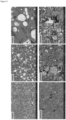
- Scanning Electron Microscopy (SEM) images of the GDE before and after activation clearly shows a conversion of the initial microscale catalytic materials into nanostructured particles.
- the catalytic material is a low melting point metal, i.e. having a melting point below 800 °C, in particular having a melting point below 450 °C; more in particular having a melting point below 350 °C, for use in the manufacture of a CAGDL as herein provided.
- the invention has been tested for the electrochemical conversion of carbon dioxide but can equally be used in the design of gas diffusion electrodes for other electrochemical conversion of gaseous reactants such as H 2 , N 2 or O 2 to (commodity) reaction products.
- gaseous reactants such as H 2 , N 2 or O 2 to (commodity) reaction products.
- CO 2 reduction to products, using low melting point metals were investigated by the inventors.
- Sn particles are used frequently as catalyst.
- the invention for this particular purpose is a Sn based porous GDE structure without support material leading to an increased surface area without compromising the electrocatalytic activity of CO 2 R i.e. the Faradaic efficiency to formic acid has not decreased.
- another set of experiments proved enhanced current densities using Pb as a catalyst for conversion of CO 2 to oxalate.
- the porosity is controlled by the amount of pore forming material (e.g. ammonium bicarbonate) and different pore sizes can be realized by changing the particle size of the pore forming material (e.g. ammonium bicarbonate) which is used in the production process .
- pore forming material e.g. ammonium bicarbonate
- this carbon-free GDE comprising a CAGDL
- the conductivity of this carbon-free GDE is strongly increased when compared to traditional GDEs wherein the catalytic material is coated on a carbon-support, which together with the enhanced catalytic surface area (see the structural modification that follows after the Joule heating) of the GDE leads to an increase of current densities by a factor 15-50.
- a derived advantage is the scalability of these GDEs that have become much easier to fabricate and cheaper overall.
- a gas diffusion layer was prepared by physically mixing ammonium bicarbonate and PTFE in a 30:70 weight ratio. The mix was pressed with a pressure of 0.1 t/cm 2 and the resulting cake was calendared to a thickness of 0.5 mm.
- the catalyst layer was prepared by mixing a Sn or Pb powder, PTFE and ammonium bicarbonate in a weight ratio of respectively 70:10:20 and 78:7:15. The mix was pressed with a pressure of 0.1 t/cm 2 and the resulting cake was calendared to a thickness of 0.5 mm. The two layers were fixed together by calendaring them together, down to a total thickness of 0.6mm. The electrode was consequently kept at 105 °C overnight to decompose the ammonium bicarbonate.
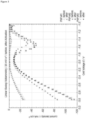
- the figures 2D and 2E show Linear Sweep Voltammetry (LSV) experiments recorded before and after electrochemical pretreatment involving electrical Joule heating. This pretreatment can be carried out via different procedures such as:
- the experiments with the Sn GDE were carried out in a two-compartment flow cell with CO 2 saturated 0.5 M KHCO 3 as catholyte and 0.5-1 M KOH as anolyte.
- the counter electrode was a platinized tantalum plate and the potential was measured with respect to a Ag/AgCl reference electrode.
- the activation via cycling ( Fig. 2B ) was performed at a scan rate of 500 mV/s/.
- the LSV was recorded at a scan rate of 20 mV/s in a one compartment cell employing 6 M KOH.
- the shown electrode potential ( Fig. 3 ) is measured against the mixed metal oxide anode.
- the LSV was recorded with a 3 mL/min electrolyte flow rate with a CO 2 gas flow rate of 50 mL/min.
- the measured current at a given potential is significantly increased when comparing the LSV before and after activation ( Fig. 2D ). This indicates a significant increase in activity (towards CO 2 reduction, Fig. 2E ) of the GDE, likely due to an increase of the accessible electrochemical active sites in the GDE.
- XRD X-ray Diffraction
- XPS X-ray Photoelectron Spectroscopy
- Teflon (PTFE) content decreases leading to an increased conductivity, as can be seen from Table 1, showing the in-plane resistance of the Sn based carbon free GDE before (pristine) and after activation. After activation the resistance has significantly decreased, indicating an increase in conductivity by the activation procedure.
- Table 1 In-plane resistance of Sn GDEs In-plane resistance Pristine electrode Activated electrode 1-10 MOhm ⁇ 1 Ohm
Landscapes
- Chemical & Material Sciences (AREA)
- Engineering & Computer Science (AREA)
- Chemical Kinetics & Catalysis (AREA)
- Electrochemistry (AREA)
- Materials Engineering (AREA)
- Metallurgy (AREA)
- Organic Chemistry (AREA)
- Inert Electrodes (AREA)
- Electrolytic Production Of Non-Metals, Compounds, Apparatuses Therefor (AREA)
Abstract
Description
- The present invention relates to a novel approach of obtaining a gas diffusion electrode (GDE), the GDEs obtained using said method and the use thereof in the electrocatalytic conversion of gaseous reactants into economically interesting reaction products. The GDEs obtained using the method of the present invention are particularly useful in the electrochemical conversion of gaseous reactants such as CO2, H2, N2, or O2 into bulk chemicals and fuels such as Syngas, Formic Acid, Methanol, Ethanol, Ethane, Ethylene, Methane, Ammonia, and the like.
- The invention comprises the development of a Gas Diffusion Electrode (GDE) to be used in electrolyzers to efficiently convert gaseous reactants such as CO2, H2, N2 or O2 electrochemically to (commodity) reaction products. The electrocatalytic conversion of these small molecules is promising in view of renewable energy storage (RES) and electrification of the chemical industry.
- A GDE is a combination of porous structures exhibiting a hydrophilic and a hydrophobic side. It is generally composed of a catalyst layer (CL), a gas diffusion layer (GDL) and a current collector (CC) as shown in
Figure 1 . A GDE allows the direct supply of gases via the hydrophobic side to the liquid medium where electrochemical processes take place. Because of their low mass transfer resistance, the use of GDEs is promising for electrochemical processes with gaseous reactants. Because of their high porosity, GDEs have a reactive surface area much larger than their geometrical area (projected surface area), which is favorable for the process productivities. The GDL is a porous medium that facilitates transport of gaseous reactants to and gaseous products from the CL and consists of a macro-porous layer either with or without a micro-porous layer (MPL). A wide variety of GDL parameters have been investigated to enhance electrolyzer or fuel cell performance (Omrani R, Shabani B (2017) Gas diffusion layer modifications and treatments for improving the performance of proton exchange membrane fuel cells and electrolysers: A review. Int J Hydrogen Energy 42:28515-28536. doi: 10.1016/j.ijhydene.2017.09.132). - The industrial or large-scale implementation of GDEs is currently however hindered by moderate current densities, large overpotentials (thus low energetic efficiency) and poor stability of the electrode structure. The required overpotential for a given electrode half reaction is determined by a number of factors:
- 1. the intrinsic electrocatalytic activity of the electron donor/acceptor material and the specific reaction pathway(s) that can occur on the surface (electrocatalyst)
- 2. the local and surface concentrations of all species that take part or influence the charge transfer steps.
- For a complete redox (cell) system, one needs to consider both anode and cathode reactions and add the resistive parts of the electrolyte (ionic resistance) and the contacts (electronic conductance), all a function of the resulting (or applied) current density. Also, the stability of GDEs is still underexplored leading to little insight in degradation mechanisms.
- The following aspects of GDEs can be considered as bottlenecks:
- Little availability of catalytic sites due to inactive (carbon) support material in the catalyst layer leading to relatively low faradaic efficiency and partial current density
- Difficulty to control the porosity of the GDL
- Conductivity is strongly dependent on type and amount of carbon support. If activated carbon is used, incorporation of an additional current collector into the GDE (see
Figure 1 ) is needed which may for example reduce the selectivity of CO2R (generating more H2). If a graphite support is used, the conductivity is better, however the obtained current is lower due to lower specific surface area of graphite) - Electrode production includes a catalyst coating step in the support material which complicates the manufacturing of the electrode (throughput, uniform quality) as well as its scale-up.
- GDEs for emerging technologies such as electrochemical reduction of CO2 and N2, and biomass oxidation are not durable with long term instability of the GDL. Moreover, it is unclear what causes the instability.
- The main problem that is solved by the GDEs of the present invention is that significantly larger partial currents can be obtained since no carbon support is used. Moreover, the availability of catalytically active species is significantly increased since the Catalytic Layer is not spray coated onto the support material but, as further detailed hereinafter, forms a homogeneous porous structure with the material of the GDL of which the porosity, conductivity and catalyst can be controlled and tuned. As the nature of the catalytically active material can easily be changed, the GDE of this invention can be adapted for use in various electrocatalytic reactions e.g. CO2 reduction, N2 reduction, O2 reduction, etc.
- With the new GDE the current densities are strongly enhanced without a decrease in Faradaic efficiency or stability.
- The present invention is based on the finding that assembly of a Gas Diffusion Electrode (GDE) can greatly be simplified by integration of the Catalyst Layer in the Gas Diffusion Layer. It has been found that the typical integration of a layer of a conductive carbon support for the catalytic material can be omitted in the design of the GDEs according to the invention. Said GDEs are characterized in that the catalytically active material is mixed with, integrated in and distributed over the porous material of the Gas Diffusion Layer (GDL), and accordingly allows omission of a separate Catalyst Layer (CL) typically found in GDEs. Expressed differently, in the GDEs of the instant application, the GDL and the Catalytic Layer are combined in one single layer, hereinafter also referred to as the Catalytically Active Gas Diffusion Layer (CAGDL).
- As will be further detailed hereinafter, the CAGDL may be manufactured by mixing the catalytic material with the base materials making up the porous GDE in the absence of a conductive carbon support for the catalytic material, followed by exposing the mixture comprising the base material and the catalytic material to an electrochemical activation step, thereby realizing the CAGDL. This electrochemical activation step involves Joule heating of the composition by curing the mixture of the catalytic material with the material(s) making up the porous material of the gas diffusion layer (GDL). The thus activated GDL is hereinafter also referred to as the sintered GDL. The base materials making up a porous GDL typically include a porous binder, hereinafter also referred to as a porous binder support material or binder material, optionally further comprising pore forming materials, i.e. materials that enable the formation of pores in the base material, such as ammonium bicarbonate (ambic), which forms pores in the porous binder support material upon curing, but lacks the carbon conductive support typically found in GDEs. In one embodiment the catalytic material is admixed with said pore forming material when added to the base materials, i.e. the porous binder support material making up the GDL.
- Thus in a first aspect the present invention provides a GDE comprising an Catalytically Active Gas Diffusion Layer (CAGDL) characterized in that catalytic material is distributed within the porous support matrix of the Gas Diffusion Layer in the absence of a conductive carbon support. In principle any porous binder material known to be used in the manufacture of the GDL of GDEs can be used, but in one embodiment the binder material is a polymeric porous material, in particular a thermoplastic porous material, such as polytetrafluoroethylene (PTFE). In one embodiment the binder material is preferably a polymeric material such as one or more polymers selected from the group of polyvinylidine fluoride (PVDF), polyvinyl alcohols, polystyrenes, organic silicates, aliphatic silanes, or any other polymer or organic material having the desired properties, and present in particle form (over the entire range of available molecular weights for polymer materials). The particulate polymer or organic material may be used either as a powder, a dispersion of particles, a suspension of particles, or any other heterogeneous mixture comprising the particles.
- In one embodiment, the catalytic material used in the GDEs comprises a low melting point metal having a melting point below 800 °C, such as Sn, Cd, Zn, Pb, Sb, Bi or eutectic compositions therefore, i.e. Ag-Cu 779, Sn-Bi and the like. In the manufacture of the CAGDL, this catalytic material is preferably mixed as a metallic powder with the polymeric binder material. Arguably such GDL materials can be found to exist, but will always require the presence of a current collector, e.g. a central metal screen of Indium plated tin in
US 2019/256990 or a stainless steel mesh inWO2015/139129 ) or of a metal carrier that acts as current distributer admixed into the materials making up the GDE, in order to provide sufficient electrical conductivity to the GDE. The present invention is based on the finding that an activation of the GDL's as herein disclosed, allows them to be used directly as CAGDL's, i.e. even in the absence of an additional current collector or current distributor while exhibiting sufficient electrical conductivity. As will be apparent from the examples, the CAGDL's have undergone a structural modification, including melting and sintering of metal particles (such as Sn particles) followed by recrystallization leading to nanostructured metal particles (e.g. Sn) present in the activated GDL's (also referred to as CAGDL) and a more porous morphology, yielding a significant reduction in resistance and a significant increase in current at a given potential. It is accordingly an object of the present invention to provide a Gas Diffusion Electrode (GDE) comprising a Catalytic Activated Gas Diffusion Layer (CAGDL), wherein the CAGDL layer consists of an electrochemically sintered Gas Diffusion Layer (GDL) comprising a catalytic material homogenously distributed within the GDL, said GDL further comprising a porous binder material and, characterized in that said catalytic material is present within the sintered GDL in the absence of a conductive carbon support for said catalytic material, and in the catalytic material is present within the sintered GDL as nanostructured particles. The nanostructured particles are typically characterized in all three dimensions of said particles being in the nanoscale, in particular with an average length range of approximate 1 nm to 100 nm; in particular with an average length range of approximate 10 nm to 100 nm; in particular with an average length range of approximate 20 nm to 100 nm; even more in particular with an average length range of approximate 30 nm to 100 nm; in an even further embodiment with an average length range of approximate 40 nm to 100 nm. - In a second aspect the present invention provides a method of manufacturing a GDE comprising a CAGDL according to the invention, said method including mixing a catalytic material with material(s) typically used in the manufacture of the porous support matrix of a GDL, and exposing the thus obtained composition to an electrochemical activation step, thereby realizing the CAGDL. In one embodiment of realizing the CAGDL, a powder of the catalytic material is mixed with a material that provides/may be transformed into the porous binder support matrix for the catalytic material particles. The method of manufacturing may in a preferred embodiment further include a curing step and an electrochemical activation step. In one embodiment the electrochemical activation involves Joule heating of the composition obtained by mixing the catalytic material with the base material(s) making the porous GDL as herein described; with the purpose of producing an electrically conductive CAGDL.
- As further detailed hereinafter, the Joule activation includes applying a potential to said mixture; in particular of the cured mixture; comprising the catalytic material, the binder material(s) and the optional pore former until the current reaches absolute values around or larger than 1 A/cm2.
-
- Figure 1.
- Schematic diagram of a prior art Gas Diffusion Electrode
- Figure 2A
- Current vs. time profile of the activation of a Sn GDE at different potentials (E =-6V: black curve, E = -4 V: grey curve, E = -2 V: black dashed curve),
- Figure 2B
- Cyclic voltammograms during activation of a Sn GDE via cycling between E = -1 V and E = -8 V
- Figure 2C
- Potential and current vs. time profiles for the activation of a Sn GDE via application of potential steps from E = -1 V to E = -8 V with a step time of 5 s.
- Figure 2D
- Linear Sweep Voltammograms of Sn GDE in a microflowcell for respectively an untreated GDE (crosses) and an activated GDE (circles)
- Figure 2E
- Linear Sweep Voltammograms of Sn GDE in a microflowcell for respectively an untreated GDE (triangles), an activated GDE without CO2 (crosses) and with CO2 (circles).
- Figure 3
- Linear Sweep Voltammograms of three Pb GDEs in a microflowcell for;
- a first Pb GDE : grey + (untreated) black + (treated);
- a second Pb GDE : grey □ (untreated) black □ (treated);
- a third Pb GDE : grey Δ (untreated) black Δ (treated)
- Figure 4
- Surface content of O, Sn, K and Cl (left) and F (right) for pristine and activated Sn GDE based on XPS analysis
- Figure 5
- SEM images of a pristine Sn GDE (top) and an activated Sn GDE (bottom) at 120x, 500x and 2500x magnification according to the invention.
- The porous material for the gas diffusion layer of the invention is based on a polymeric porous binder material or porous inorganic binder material with the polymeric porous binder material preferred over the porous inorganic material, similar to the materials typically used in the GDL of a GDE, but characterized in the absence of a conductive carbon support for the catalytic material. As mentioned herein before, in a standard GDE, the catalytic material is applied onto a carbon support material. In the CAGDL of the present invention, such carbon support is not required, instead the catalytic materials is admixed directly with the materials used in the manufacture of the GDL, and exposed to an electrochemical activation step, i.e. activation by Joule heating realizing the required electrical conductivity. The polymeric porous binder material can be selected from foams, bundled fibers, matted fibers, needled fibers, woven or nonwoven fibers, porous polymers made by pressing polymer beads, Porex and Porex like polymers. Suitable polymer materials include, i. e. porous polyolefins such as porous polyethylene or porous polypropylene which can be prepared by blending two polymers and removing one of the polymers by dissolving it. The porous polymeric material is preferably selected from bundled fibers, matted fibers, needled fibers, and woven or nonwoven fibers. More preferably, the porous polymeric material is selected from nonwoven felts, woven fibers or bundles of fibers made of polyamide such as nylon, polyethylene, polypropylene, polyester such as polyethylene terephthalate, cellulose, modified cellulose such as Rayon, polyacrylonitrile, and mixtures thereof. Other suitable porous polymeric materials include polyvinylidine fluoride (PVDF), polytetrafluoroethylene (PTFE), polyvinyl alcohols, polystyrenes, organic silicates, aliphatic silanes, or any other polymer. Besides the afore-mentioned polymeric materials, the binder material may comprise or be made of an organic material having the desired properties, in particle form over the entire range of available molecular weights for polymer materials either as a powder, dispersion, suspension, or any other heterogeneous mixture.
- The porous binder material of the CAGDL will preferably have a porosity in the range of about 5 to about 150 pores per inch (ppi), and a density in the range of about 0.5 to about 8.0 pounds per cubic foot.
- The porous material can be of any physical shape as long as it has at least one flat surface for making contact with one of the electrodes when the gas diffusion layer is installed in for example a fuel cell, or any other surface suitable for establishing a desired contact with the electrode. Thus, for example when the porous material of a GDL of the invention comprises a foam such as a flexible reticulated polyurethane foam, the foam can be of any physical shape when not compressed and not installed in a fuel cell as long as the foam, uncompressed or compressed, has at least one surface adapted for making contact with an electrode when installed in a fuel cell.
- In the manufacture of the Catalytically Active Gas Diffusion Layer (CAGDL), this binder material, and in particular the polymeric binder material is admixed with the catalytic material. In one embodiment, the particulate polymeric binder material is admixed with the catalytic material and with a pore forming material, i.e. a material that enables the formation of pores in the polymeric binder material, such as ammonium bicarbonate (ambic), and the like. In a preferred embodiment a powder of the particulate polymeric binder material is admixed with a powder of the catalytic material and with a powder of the pore forming material.
- A powder is a dry, bulk solid composed of many very fine particles that may flow freely when shaken or tilted. Powders are a sub-class of particulate materials and refers to those particulate materials that have the finer grain sizes, and that therefore have a greater tendency to form clumps when flowing. As a general rule any discrete particles whose sizes are less than 1 mm are called powders.
- For example, in one embodiment bulk powder (commercial) of the catalytic material is mixed with a powdery binder material, preferably a powdery polymeric binding agent, such as polytetrafluoroethylene (PTFE). The pore former, e.g. ambic is also added to this mix. In a subsequent step this mixture will be shaped be it by cold rolling, stepwise pressing, agglomeration, or combinations thereof.
- In the examples hereinafter the powder materials were mixed together as they were, (step wise so heat by friction was not produced). In preparing the mixtures, it is important to try and obtain homogenous mixtures. In particular the catalytic materials should be distributed as homogenously as possible in the mixture of particulate powders materials used in the manufacture of the CAGDL. 'Homogenous' as used herein implies the same in all directions, i.e. having the same density and of the same kind or substance, respectively. Homogenously particulate material blending techniques are known in the art and rely on a vigorous mixing of at least two feed streams, such as for example using high shear vertical mixers, high shear horizontal pin or ring mixers, low shear drum mixers or fluidised bed systems. These mixtures were then either pressed slowly and in steps (5 Ton, 10 Ton, 15 Ton), or pressed into a cake, such as for example using a hydraulic press of 20 Ton and cold-rolled to the investigated thickness. In one embodiment the cold-rolling is effected in various rolling-steps of which the amount lies by preference between 10 µm and 50 µm, especially between 30 µm and 45 µm. In a preferred embodiment the cold-rolling is biaxial rolling as such rolling treatment increases the surface area and strengthens the mechanical cohesion of the CADGL. In such biaxial rolling every rolling-step is effected with a rolling-direction which is turned 90 degree with respect to the rolling-direction of the former step.
- The homogeneity of the mixture can be enhanced by pre-treatment of the particulate / powdery components, i.e. of the polymeric binder support, the catalytic material, and the pore forming material , in order to get a mixture homogenous in particle size. Such treatment could be a size selection of the source materials, but equally consist of grinding the source materials and/or the mixture, e.g. on laboratory scale in a blender. With the objective of realizing CAGDL as thin as a couple of mm's, the average particle size of the powdery components is preferably smaller than 1 mm.
- Both the cake and the cold-rolled layer can be used as a CAGDL in the electrode as evident from the examples hereinafter. In either instance the last step in the manufacture of the CAGDL is a curing step wherein the cake pressed or cold-rolled layer is placed in an oven to sublimate the pore former from the composition, such as overnight at 70 °C to sublimate the pore former Ambic which creates the pores in the material. Once cured, the electrode material is exposed to an electrochemical activation procedure, i.e. by Joule Heating to achieve the Catalytic Activated Gas Diffusion Layer (CAGDL). As detailed in the examples hereinafter, the Joule heating can occur via different procedures but commonly includes applying a potential at the electrode material until the current reaches absolute values around or larger than 1 A/cm2. To realize the Joule heating, the potential can be applied; (1) by applying a constant potential at the electrode material for a time until the current reaches absolute values around or larger than 1 A/cm2; (2) by cycling the potential within a specific potential range for numerous cycles until the current reaches values around 1 A/cm2; or (3) by applying potential pulses or steps to values large enough such that the current increases to values larger than around 1 A/cm2. In the examples (
Fig. 2A ) potentials of -1 V or more negative were applied at the cured electrode material. In a particular embodiment a potential in a range of about and between -2 V and -30 V is applied; more in particular a potential in a range of about and between -2 V and -10 V is applied. The voltage across the material can be applied at a constant value over time until the current reaches the aforementioned values, but alternatively the potential across the material can be applied in pulses or incremental steps. The duration of the pulses or steps can be between 1 microsecond and 100 seconds, in particular between 100 milliseconds and 500 milliseconds, and are repeated until the current reaches absolute values larger than 1A/cm2. The number of voltage pulses can be in a range between 1 pulse and 1000 pulses; in particular between 1 and 500 pulses, more in particular between 1 and 100 pulses. The potential of the pulses or steps is typically in the range between -2 V and -30 V. A more negative potential may lead to destruction of the electrode due to large temperature generated during the process. The time needed for the activation of the electrode depends on the combination of the aforementioned parameters (pulse/step time, pulse/step potential and number of pulses/steps). In another embodiment the potential is cycled within two values between -2 V and -30 V leading to an increased current for each step until absolute values larger than 1 A/cm2 are obtained. The time to realize a fully activated electrode is dependent on the chosen potential window, scan rates and number of cycles. Generally high scan rates are used (0.5 - 2 A/s). The key for this activation procedures is to realize large currents which enable a sintering process via the Joule effect leading to an increased conductivity of the electrode. - The skilled person is well aware of power sources that can be used to apply a constant voltage or voltage pulses/steps across the cured electrode materials as herein provided. Such power source could for example consists of a DC voltage source, optionally including a controller to set the duration of the voltage pulses/steps or number of cycles.
- In the mixtures used for the manufacture of the CAGDL layers according to the invention, high Faradaic Efficiency (FE) values are obtained in case of an excess of the catalytic material with respect to the binder material. A typical weight % ratio of catalytic material (e.g. metal powders) / pore former / binder material (e.g. PTFE) of 70/20/10 for the electrode in the formic acid synthesis hereinafter resulted in a FE > 80%. Other ratio's for the amount of catalytic material with respect to the amount of pore former and binder in the range of 50% to 80% wt of catalytic material were also tested with the same FE for formic acid synthesis. It accordingly follows that in one embodiment according to the invention the CAGDL comprises 50% to 80% wt of catalytic material with respect to the amount of binder and/or pore former material. In one embodiment the CAGDL comprises from about 50% - 80% wt of catalytic material; from about 10% - 40% wt of pore former; and from about 10% - 40% wt of binder. In one embodiment the CAGDL comprises from about 50% - 80% wt of catalytic material; from about 10% - 40% wt of pore former; and about 10% wt of binder. In another embodiment from about 50% - 80% wt of catalytic material; from about 10% - 40% wt of pore former; and from about 10% - 20% wt of binder. In another embodiment from about 60% - 80% wt of catalytic material; from about 10% - 20% wt of pore former; and from about 10% - 20% wt of binder. In another embodiment from about 60% - 80% wt of catalytic material; from about 10% - 20% wt of pore former; and about 10% of binder. In another embodiment from about 50% - 80% wt of catalytic material; from about 10% - 40% wt of pore former; and about 10% of binder. In another embodiment from about 60% - 75% wt of catalytic material; from about 15% - 30% wt of pore former; and about 10% of binder. In a particular embodiment from about 60% - 75% wt of catalytic material; about 20% wt of pore former; and about 10% of binder. In all of the tested
combinations 20% ambic gave the best result. - Mixtures used in the manufacture of the CAGDL typically include pore forming materials, i.e. materials that enable the formation of pores in the base material, such as ammonium bicarbonate, ambic, which forms pores in the porous binder support matrix upon curing. The particle size of such pore forming materials will inevitably influence the pore sizes formed in the CAGDL. Within the examples the pore former is sieved in an air sieve, so the powder size is in a range around 0,4 µm, with a corresponding porosity in the CAGDL with pore sizes in the range of 0,33 ± 0,18µm.
- The composition of the CAGDL comprises the catalytic material in a porous binder matrix. The catalytic material includes, but is not limited to corrosion-resistant metallic materials such as, but not limited to, metallic carbides, metallic nitrides, metallic borides, metallic silicates, metallic oxides, or any combinations thereof. Metalloid powders may also be used. When manufacturing the CAGDL, the catalytic materials may be used in different forms, but preferably they are used in the form of particles of the catalytic material. All of these materials may be purchased commercially in a variety of particle sizes. Desirably, substrate particle-sizes of the catalytic material should be no more than 1 mm, but preferably no more than 500 µm; in particular up to 150 µm. Preferably, the metallic powder is mixed with a material that serves as the porous binder for the catalytic particles. The porous binder material is preferably a mildly hydrophobic or hydrophilic material such as polyvinylidine fluoride (PVDF), a polyvinyl alcohol, polystyrene, an organic modified? silicate, an aliphatic silane, or any other polymer or organic material having the desired properties. The material preferably is purchased as a raw ingredient in particle form (over the entire range of available molecular weights for polymer materials) and may for example take the form of a powder, dispersion, suspension, or any other heterogeneous mixture. The average particle size of the particulate components is preferably smaller than 1 mm. Size of the support-binder particles should be no less than 0.01 µm and no more than 1 mmm, but preferably between 1 µm and 50 µm, more in particular between and about 6 µm to 20 µm. As mentioned hereinbefore, the pore forming material is also included as a particulate constituent to the mixture in the manufacture of the CAGDL and will determine the porosity of said layer. Size of the pore former particles should be no less than 0.01 µm and no more than the size of the support-binder material. In one embodiment the particle size of the pore former is between and about 0.01 µm to 10 µm, in particular up to about 2 µm. Within the examples the pore former is sieved in an air sieve, so the powder size is in a range around the 0,4 µm, with a corresponding porosity in the CAGDL with pore sizes in the range of 0,33 ± 0,18µm. As used herein, particle sizes for the catalytic material, the binder and the pore former are meant to refer to average particle sizes.
- As mentioned herein before, the gas diffusion electrode of this invention is produced by mixing a catalytic material with the material(s) used in the manufacture of a gas diffusion layer, but characterized in that the catalytic material is not applied onto a carbon support material, and exposing the thus obtained porous material to an electrochemical activation step, thereby realizing the CAGDL. The hypothesis is that Joule heating causes 'flash' sintering of the catalytic material, leading to increased electrical conductivity and catalytic active surface area. Scanning Electron Microscopy (SEM) images of the GDE before and after activation clearly shows a conversion of the initial microscale catalytic materials into nanostructured particles. The result for such activation of a Gas Diffusion Layer obtained according to the methods as herein described has been proven for Sn (melting point of about 230 °C), Sn-Zn alloy (melting point of about 200 °C) and Pb (melting point of about 330 °C) as catalytic materials in the absence of a carbon support.
- GDEs based on other catalytic materials (with low melting point Sn (±230 °C), Cd (± 320 °C) , Zn (± 420 °C), Pb (± 330°C), Sb (± 630 °C), Bi (± 270 °C) or low melt eutectic compositions such as 55,5% Bi - 44,4% Sn (± 125°C) will undergo a similar increase in electrical conductivity and catalytic surface area, through the conversion of the catalytic material into nanostructured particles. Consequently, in one embodiment according to the invention, the catalytic material is a low melting point metal, i.e. having a melting point below 800 °C, in particular having a melting point below 450 °C; more in particular having a melting point below 350 °C, for use in the manufacture of a CAGDL as herein provided.
- As will become evident from the examples hereinafter, the invention has been tested for the electrochemical conversion of carbon dioxide but can equally be used in the design of gas diffusion electrodes for other electrochemical conversion of gaseous reactants such as H2, N2 or O2 to (commodity) reaction products. In the examples below, the CO2 reduction to products, using low melting point metals were investigated by the inventors. Conventionally, for CO2 to formic acid, Sn particles are used frequently as catalyst. The invention for this particular purpose is a Sn based porous GDE structure without support material leading to an increased surface area without compromising the electrocatalytic activity of CO2R i.e. the Faradaic efficiency to formic acid has not decreased. Similarly, another set of experiments proved enhanced current densities using Pb as a catalyst for conversion of CO2 to oxalate.
- Moreover, the porosity is controlled by the amount of pore forming material (e.g. ammonium bicarbonate) and different pore sizes can be realized by changing the particle size of the pore forming material (e.g. ammonium bicarbonate) which is used in the production process .
- It has been found that the conductivity of this carbon-free GDE comprising a CAGDL is strongly increased when compared to traditional GDEs wherein the catalytic material is coated on a carbon-support, which together with the enhanced catalytic surface area (see the structural modification that follows after the Joule heating) of the GDE leads to an increase of current densities by a factor 15-50. A derived advantage is the scalability of these GDEs that have become much easier to fabricate and cheaper overall.
- A gas diffusion layer was prepared by physically mixing ammonium bicarbonate and PTFE in a 30:70 weight ratio. The mix was pressed with a pressure of 0.1 t/cm2 and the resulting cake was calendared to a thickness of 0.5 mm. The catalyst layer was prepared by mixing a Sn or Pb powder, PTFE and ammonium bicarbonate in a weight ratio of respectively 70:10:20 and 78:7:15. The mix was pressed with a pressure of 0.1 t/cm2 and the resulting cake was calendared to a thickness of 0.5 mm. The two layers were fixed together by calendaring them together, down to a total thickness of 0.6mm. The electrode was consequently kept at 105 °C overnight to decompose the ammonium bicarbonate.
- Below are the figures of the LSVs before and after activation (see "activation" step below) of the electrocatalyst. For Sn, the LSVs for two GDEs are provided,
Figures 2B and2C respectively. For Pb the before/after LSV's for three PB based GDEs are combined in a single Figure,Figure 3 , demonstrating the reproducibility of the CAGDL obtained using the method according to the invention. - For both the Sn or Pb based GDEs activation was done in a saturated KOH solution and a one compartment cell, 3 mL/min flow rate electrolyte, 50 ml/min CO2 flow rate and a Dimensionally Stable Anode (DSA) as anode.
- The
figures 2D and2E show Linear Sweep Voltammetry (LSV) experiments recorded before and after electrochemical pretreatment involving electrical Joule heating. This pretreatment can be carried out via different procedures such as: - (1) by applying a constant potential at the electrode for a time until the current reaches absolute values larger than 10 A. The time needed for this activation procedure is dependent on the potential applied as depicted in
Fig 2A . Activation at a lower potential (E = -4V) requires longer times and if the potential is too low (E = -2 V), the required current is not obtained. - (2) by cycling between a certain potential range. In
Fig. 2B cyclic voltammograms are shown for cycling the potential between E = -1 V and E = -8 V from which can be seen that the current increases with increasing cycle numbers. After around 100 cycles the current has reached absolute values > 8 A indicating the Joule effect to have taken place. - (3) by applying potential steps to a value chosen such that the Joule effect can take place. In
Fig. 2C the potential steps and corresponding current vs. time are shown. The potential steps are from E = -1V till E = -8V and last for 5 seconds. The current is increasing as a function of the time, indicating the activation of the electrode. - The experiments with the Sn GDE were carried out in a two-compartment flow cell with CO2 saturated 0.5 M KHCO3 as catholyte and 0.5-1 M KOH as anolyte. The counter electrode was a platinized tantalum plate and the potential was measured with respect to a Ag/AgCl reference electrode. The activation via cycling (
Fig. 2B ) was performed at a scan rate of 500 mV/s/. For the Pb GDE, the LSV was recorded at a scan rate of 20 mV/s in a one compartment cell employing 6 M KOH. The shown electrode potential (Fig. 3 ) is measured against the mixed metal oxide anode. The LSV was recorded with a 3 mL/min electrolyte flow rate with a CO2 gas flow rate of 50 mL/min. - The measured current at a given potential is significantly increased when comparing the LSV before and after activation (
Fig. 2D ). This indicates a significant increase in activity (towards CO2 reduction,Fig. 2E ) of the GDE, likely due to an increase of the accessible electrochemical active sites in the GDE. - X-ray Diffraction (XRD) measurement of the Sn based carbon free GDE before (pristine) and after activation shown a decrease in the intensity of tin present in the bulk of the electrode. This is also apparent from an X-ray Photoelectron Spectroscopy (XPS) analysis of the material before and after activation.
- From the XPS analysis it can be seen that the overall Sn content slightly decreases after activation (
Fig 4A ). Furthermore, the F content decreases (Fig. 4B ) which is a result of the electrochemical sintering (activation) process.Fig 4A further indicates an increase in K and Cl content after activation. This is ascribed to these species being present in the electrolyte which are adsorbed onto the electrode during activation since the electrode is immersed in the electrolyte. - The Teflon (PTFE) content decreases leading to an increased conductivity, as can be seen from Table 1, showing the in-plane resistance of the Sn based carbon free GDE before (pristine) and after activation. After activation the resistance has significantly decreased, indicating an increase in conductivity by the activation procedure.
Table 1 In-plane resistance of Sn GDEs In-plane resistance Pristine electrode Activated electrode 1-10 MOhm < 1 Ohm - That the activation effectively alters the GDE, is also apparent from Scanning Electron Microscopy (SEM) images of the GDE before and after activation (
Fig.5 ). On the pristine electrode (top images inFig. 5 ) relatively large Sn particles can be observed, while on the activated electrode much smaller Sn particles are visible. This is caused by melting followed by recrystallization of the Sn particles during the electrochemical sintering process leading to a well-dispersed distribution of nanostructured Sn which accounts for a better conductivity. Moreover, a more porous structure of the GDL is visible after activation.
Claims (7)
- A method of manufacturing a CAGDL, said method including mixing a catalytic material with material(s) for forming a GDL, characterized in said catalytic material is mixed with material(s) for forming a GDL including a binding material that serves as a porous binder matrix for the catalytic material particles, wherein the mixture comprises an excess of catalytic material with respect to the binding material, but in the absence of a conductive carbon support for the catalytic material and exposing the thus obtained composition to an electrochemical activation step, thereby realizing the electrically conductive CAGDL.
- The method according to claim 1, wherein the binding material is preferably a polymeric material such as polytetrafluorethylene (PTFE), polyvinylidine fluoride (PVDF), polyvinyl alcohols, polystyrenes, organic silicates, aliphatic silanes, or any other polymer or organic material having the desired properties, and present in particle form (over the entire range of available molecular weights for polymer materials) either as a powder, dispersion, suspension, or any other heterogeneous mixture.
- The method of claim 1, optionally further including a pore forming material to the mixture.
- The method of claim 1 wherein the mixture comprises 50% to 80% wt of catalytic material with respect to the amount of binder and/or optional pore former material.
- The method of manufacturing an CAGDL according to any one of claims 1 to 4, further including a curing step; in particular to evaporate the pore former
- The method according to any one of claims 1 to 5, further including electrochemical activation of the CAGDL by electrical Joule heating of the mixture; in particular of the cured mixture; comprising the catalytic material, the binder material(s) and the optional pore former.
- The method according to claim 6, wherein the Joule activation includes applying a potential at the mixture; in particular of the cured mixture; comprising the catalytic material, the binder material(s) and the optional pore former until the current reaches absolute values around or larger than 1 A/cm2.
Applications Claiming Priority (3)
| Application Number | Priority Date | Filing Date | Title |
|---|---|---|---|
| EP20185780 | 2020-07-14 | ||
| PCT/EP2021/068896 WO2022013042A1 (en) | 2020-07-14 | 2021-07-07 | Carbon free gas diffusion electrode |
| EP21740058.9A EP4182491B1 (en) | 2020-07-14 | 2021-07-07 | Carbon free gas diffusion electrode |
Related Parent Applications (2)
| Application Number | Title | Priority Date | Filing Date |
|---|---|---|---|
| EP21740058.9A Division-Into EP4182491B1 (en) | 2020-07-14 | 2021-07-07 | Carbon free gas diffusion electrode |
| EP21740058.9A Division EP4182491B1 (en) | 2020-07-14 | 2021-07-07 | Carbon free gas diffusion electrode |
Publications (2)
| Publication Number | Publication Date |
|---|---|
| EP4375399A2 true EP4375399A2 (en) | 2024-05-29 |
| EP4375399A3 EP4375399A3 (en) | 2024-08-07 |
Family
ID=71620190
Family Applications (2)
| Application Number | Title | Priority Date | Filing Date |
|---|---|---|---|
| EP24161441.1A Pending EP4375399A3 (en) | 2020-07-14 | 2021-07-07 | Carbon free gas diffusion electrode |
| EP21740058.9A Active EP4182491B1 (en) | 2020-07-14 | 2021-07-07 | Carbon free gas diffusion electrode |
Family Applications After (1)
| Application Number | Title | Priority Date | Filing Date |
|---|---|---|---|
| EP21740058.9A Active EP4182491B1 (en) | 2020-07-14 | 2021-07-07 | Carbon free gas diffusion electrode |
Country Status (4)
| Country | Link |
|---|---|
| US (1) | US20230313392A1 (en) |
| EP (2) | EP4375399A3 (en) |
| CN (1) | CN116194620A (en) |
| WO (1) | WO2022013042A1 (en) |
Families Citing this family (3)
| Publication number | Priority date | Publication date | Assignee | Title |
|---|---|---|---|---|
| US20230265569A1 (en) * | 2022-02-21 | 2023-08-24 | Xerox Corporation | Amine-functionalized silver nanoparticles for gas diffusion electrodes |
| EP4474526A1 (en) | 2023-06-05 | 2024-12-11 | Vito NV | Re-activation process of gas diffusion electrode |
| WO2025042924A1 (en) * | 2023-08-20 | 2025-02-27 | Susteon Inc. | Electrically heated substrates, assemblies, systems, and processes for catalytic, chemical, and sorbent applications |
Citations (2)
| Publication number | Priority date | Publication date | Assignee | Title |
|---|---|---|---|---|
| WO2015139129A1 (en) | 2014-03-17 | 2015-09-24 | Sean Huff | Gas-contacting electrodes for use in continuous electrochemical reactors and method of making the same |
| US20190256990A1 (en) | 2012-07-26 | 2019-08-22 | Avantium Knowledge Centre B.V. | Method and System for Electrochemical Reduction of Carbon Dioxide Employing a Gas Diffusion Electrode |
Family Cites Families (2)
| Publication number | Priority date | Publication date | Assignee | Title |
|---|---|---|---|---|
| US4568442A (en) * | 1985-02-01 | 1986-02-04 | The Dow Chemical Company | Gas diffusion composite electrode having polymeric binder coated carbon layer |
| DE102017204096A1 (en) * | 2017-03-13 | 2018-09-13 | Siemens Aktiengesellschaft | Production of gas diffusion electrodes with ion transport resins for the electrochemical reduction of CO2 to chemical recyclables |
-
2021
- 2021-07-07 EP EP24161441.1A patent/EP4375399A3/en active Pending
- 2021-07-07 EP EP21740058.9A patent/EP4182491B1/en active Active
- 2021-07-07 CN CN202180061377.6A patent/CN116194620A/en active Pending
- 2021-07-07 US US18/014,827 patent/US20230313392A1/en active Pending
- 2021-07-07 WO PCT/EP2021/068896 patent/WO2022013042A1/en not_active Ceased
Patent Citations (2)
| Publication number | Priority date | Publication date | Assignee | Title |
|---|---|---|---|---|
| US20190256990A1 (en) | 2012-07-26 | 2019-08-22 | Avantium Knowledge Centre B.V. | Method and System for Electrochemical Reduction of Carbon Dioxide Employing a Gas Diffusion Electrode |
| WO2015139129A1 (en) | 2014-03-17 | 2015-09-24 | Sean Huff | Gas-contacting electrodes for use in continuous electrochemical reactors and method of making the same |
Non-Patent Citations (1)
| Title |
|---|
| OMRANI RSHABANI B: "Gas diffusion layer modifications and treatments for improving the performance of proton exchange membrane fuel cells and electrolysers: A review", INT J HYDROGEN ENERGY, vol. 42, 2017, pages 28515 - 28536, XP085277789, DOI: 10.1016/j.ijhydene.2017.09.132 |
Also Published As
| Publication number | Publication date |
|---|---|
| CN116194620A (en) | 2023-05-30 |
| EP4182491C0 (en) | 2025-07-02 |
| EP4182491B1 (en) | 2025-07-02 |
| EP4375399A3 (en) | 2024-08-07 |
| EP4182491A1 (en) | 2023-05-24 |
| US20230313392A1 (en) | 2023-10-05 |
| WO2022013042A1 (en) | 2022-01-20 |
Similar Documents
| Publication | Publication Date | Title |
|---|---|---|
| Xie et al. | Ultrathin platinum nanowire based electrodes for high-efficiency hydrogen generation in practical electrolyzer cells | |
| EP4182491B1 (en) | Carbon free gas diffusion electrode | |
| Domínguez-Domínguez et al. | Electrochemical deposition of platinum nanoparticles on different carbon supports and conducting polymers | |
| Marie et al. | Highly dispersed platinum on carbon aerogels as supported catalysts for PEM fuel cell-electrodes: comparison of two different synthesis paths | |
| US6344291B1 (en) | Solid polymer electrolyte-catalyst composite electrode, electrode for fuel cell, and process for producing these electrodes | |
| JP2988938B2 (en) | Method for producing a plastic-bonded gas diffusion electrode having a manganese oxide catalyst having a main composition of Mn lower 2 O lower 3 Xn lower 5 O lower 8 | |
| US5171644A (en) | Electrochemical cell electrode | |
| Ferner et al. | Composite anode for PEM water electrolyzers: lowering iridium loadings and reducing material costs with a conductive additive | |
| CN110770370B (en) | Gas diffusion electrode for reducing carbon dioxide | |
| US5314760A (en) | Electrochemical cell electrode | |
| US3676222A (en) | Conductive carbon membrane electrode | |
| CA2466362C (en) | Improved rhodium electrocatalyst and method of preparation | |
| US3385736A (en) | Method of making electrode from viscoelastic dough | |
| Zhou et al. | Effects of conductive polyaniline (PANI) preparation and platinum electrodeposition on electroactivity of methanol oxidation | |
| Bai et al. | Electrodeposition of cobalt nickel hydroxide composite as a high-efficiency catalyst for hydrogen evolution reactions | |
| JPS6059996B2 (en) | Alkali chloride electrolysis method | |
| WO2021262323A2 (en) | Electrocatalysts and electrolyzers | |
| US20210207277A1 (en) | Gas diffusion electrode for carbon dioxide treatment, method for production thereof, and electrolysis cell having a gas diffusion electrode | |
| US20040086772A1 (en) | Fuel cell electrode comprising CO and sulfur tolerant metal compound hydrogen activation catalyst | |
| US3668014A (en) | Electrode and method of producing same | |
| Sorsa et al. | Optimization and aging of Pt nanowires supported on single-walled carbon nanotubes as a cathode catalyst in polymer electrolyte membrane water electrolyser | |
| Holze et al. | Double-layer capacity measurements as a method to characterize porous fuel cell electrodes | |
| CN107630230A (en) | oxygen-consuming electrode and preparation method thereof | |
| Vaarmets et al. | Accelerated durability tests of molybdenum carbide derived carbon based Pt catalysts for PEMFC | |
| US8449739B2 (en) | Metal-coated carbon surfaces for use in fuel cells |
Legal Events
| Date | Code | Title | Description |
|---|---|---|---|
| STAA | Information on the status of an ep patent application or granted ep patent |
Free format text: STATUS: UNKNOWN |
|
| PUAI | Public reference made under article 153(3) epc to a published international application that has entered the european phase |
Free format text: ORIGINAL CODE: 0009012 |
|
| STAA | Information on the status of an ep patent application or granted ep patent |
Free format text: STATUS: REQUEST FOR EXAMINATION WAS MADE |
|
| 17P | Request for examination filed |
Effective date: 20240305 |
|
| AC | Divisional application: reference to earlier application |
Ref document number: 4182491 Country of ref document: EP Kind code of ref document: P |
|
| AK | Designated contracting states |
Kind code of ref document: A2 Designated state(s): AL AT BE BG CH CY CZ DE DK EE ES FI FR GB GR HR HU IE IS IT LI LT LU LV MC MK MT NL NO PL PT RO RS SE SI SK SM TR |
|
| PUAL | Search report despatched |
Free format text: ORIGINAL CODE: 0009013 |
|
| AK | Designated contracting states |
Kind code of ref document: A3 Designated state(s): AL AT BE BG CH CY CZ DE DK EE ES FI FR GB GR HR HU IE IS IT LI LT LU LV MC MK MT NL NO PL PT RO RS SE SI SK SM TR |
|
| RIC1 | Information provided on ipc code assigned before grant |
Ipc: C25B 11/055 20210101ALI20240704BHEP Ipc: C25B 11/091 20210101ALI20240704BHEP Ipc: C25B 11/032 20210101AFI20240704BHEP |