EP4375196A1 - Aircraft pipework assembly - Google Patents
Aircraft pipework assembly Download PDFInfo
- Publication number
- EP4375196A1 EP4375196A1 EP23211593.1A EP23211593A EP4375196A1 EP 4375196 A1 EP4375196 A1 EP 4375196A1 EP 23211593 A EP23211593 A EP 23211593A EP 4375196 A1 EP4375196 A1 EP 4375196A1
- Authority
- EP
- European Patent Office
- Prior art keywords
- pipework
- aircraft
- tie rod
- ball
- bearing
- Prior art date
- Legal status (The legal status is an assumption and is not a legal conclusion. Google has not performed a legal analysis and makes no representation as to the accuracy of the status listed.)
- Granted
Links
Images


Classifications
-
- F—MECHANICAL ENGINEERING; LIGHTING; HEATING; WEAPONS; BLASTING
- F16—ENGINEERING ELEMENTS AND UNITS; GENERAL MEASURES FOR PRODUCING AND MAINTAINING EFFECTIVE FUNCTIONING OF MACHINES OR INSTALLATIONS; THERMAL INSULATION IN GENERAL
- F16L—PIPES; JOINTS OR FITTINGS FOR PIPES; SUPPORTS FOR PIPES, CABLES OR PROTECTIVE TUBING; MEANS FOR THERMAL INSULATION IN GENERAL
- F16L27/00—Adjustable joints; Joints allowing movement
- F16L27/02—Universal joints, i.e. with mechanical connection allowing angular movement or adjustment of the axes of the parts in any direction
- F16L27/023—Universal and rotating joints
-
- B—PERFORMING OPERATIONS; TRANSPORTING
- B64—AIRCRAFT; AVIATION; COSMONAUTICS
- B64D—EQUIPMENT FOR FITTING IN OR TO AIRCRAFT; FLIGHT SUITS; PARACHUTES; ARRANGEMENT OR MOUNTING OF POWER PLANTS OR PROPULSION TRANSMISSIONS IN AIRCRAFT
- B64D37/00—Arrangements in connection with fuel supply for power plant
-
- B—PERFORMING OPERATIONS; TRANSPORTING
- B64—AIRCRAFT; AVIATION; COSMONAUTICS
- B64D—EQUIPMENT FOR FITTING IN OR TO AIRCRAFT; FLIGHT SUITS; PARACHUTES; ARRANGEMENT OR MOUNTING OF POWER PLANTS OR PROPULSION TRANSMISSIONS IN AIRCRAFT
- B64D37/00—Arrangements in connection with fuel supply for power plant
- B64D37/005—Accessories not provided for in the groups B64D37/02 - B64D37/28
-
- B—PERFORMING OPERATIONS; TRANSPORTING
- B64—AIRCRAFT; AVIATION; COSMONAUTICS
- B64D—EQUIPMENT FOR FITTING IN OR TO AIRCRAFT; FLIGHT SUITS; PARACHUTES; ARRANGEMENT OR MOUNTING OF POWER PLANTS OR PROPULSION TRANSMISSIONS IN AIRCRAFT
- B64D37/00—Arrangements in connection with fuel supply for power plant
- B64D37/30—Fuel systems for specific fuels
-
- F—MECHANICAL ENGINEERING; LIGHTING; HEATING; WEAPONS; BLASTING
- F16—ENGINEERING ELEMENTS AND UNITS; GENERAL MEASURES FOR PRODUCING AND MAINTAINING EFFECTIVE FUNCTIONING OF MACHINES OR INSTALLATIONS; THERMAL INSULATION IN GENERAL
- F16L—PIPES; JOINTS OR FITTINGS FOR PIPES; SUPPORTS FOR PIPES, CABLES OR PROTECTIVE TUBING; MEANS FOR THERMAL INSULATION IN GENERAL
- F16L27/00—Adjustable joints; Joints allowing movement
- F16L27/02—Universal joints, i.e. with mechanical connection allowing angular movement or adjustment of the axes of the parts in any direction
- F16L27/026—Universal and axially displaceable joints
-
- F—MECHANICAL ENGINEERING; LIGHTING; HEATING; WEAPONS; BLASTING
- F16—ENGINEERING ELEMENTS AND UNITS; GENERAL MEASURES FOR PRODUCING AND MAINTAINING EFFECTIVE FUNCTIONING OF MACHINES OR INSTALLATIONS; THERMAL INSULATION IN GENERAL
- F16L—PIPES; JOINTS OR FITTINGS FOR PIPES; SUPPORTS FOR PIPES, CABLES OR PROTECTIVE TUBING; MEANS FOR THERMAL INSULATION IN GENERAL
- F16L27/00—Adjustable joints; Joints allowing movement
- F16L27/02—Universal joints, i.e. with mechanical connection allowing angular movement or adjustment of the axes of the parts in any direction
- F16L27/04—Universal joints, i.e. with mechanical connection allowing angular movement or adjustment of the axes of the parts in any direction with partly-spherical engaging surfaces
-
- F—MECHANICAL ENGINEERING; LIGHTING; HEATING; WEAPONS; BLASTING
- F16—ENGINEERING ELEMENTS AND UNITS; GENERAL MEASURES FOR PRODUCING AND MAINTAINING EFFECTIVE FUNCTIONING OF MACHINES OR INSTALLATIONS; THERMAL INSULATION IN GENERAL
- F16L—PIPES; JOINTS OR FITTINGS FOR PIPES; SUPPORTS FOR PIPES, CABLES OR PROTECTIVE TUBING; MEANS FOR THERMAL INSULATION IN GENERAL
- F16L3/00—Supports for pipes, cables or protective tubing, e.g. hangers, holders, clamps, cleats, clips, brackets
- F16L3/16—Supports for pipes, cables or protective tubing, e.g. hangers, holders, clamps, cleats, clips, brackets with special provision allowing movement of the pipe
-
- F—MECHANICAL ENGINEERING; LIGHTING; HEATING; WEAPONS; BLASTING
- F16—ENGINEERING ELEMENTS AND UNITS; GENERAL MEASURES FOR PRODUCING AND MAINTAINING EFFECTIVE FUNCTIONING OF MACHINES OR INSTALLATIONS; THERMAL INSULATION IN GENERAL
- F16L—PIPES; JOINTS OR FITTINGS FOR PIPES; SUPPORTS FOR PIPES, CABLES OR PROTECTIVE TUBING; MEANS FOR THERMAL INSULATION IN GENERAL
- F16L5/00—Devices for use where pipes, cables or protective tubing pass through walls or partitions
-
- F—MECHANICAL ENGINEERING; LIGHTING; HEATING; WEAPONS; BLASTING
- F16—ENGINEERING ELEMENTS AND UNITS; GENERAL MEASURES FOR PRODUCING AND MAINTAINING EFFECTIVE FUNCTIONING OF MACHINES OR INSTALLATIONS; THERMAL INSULATION IN GENERAL
- F16L—PIPES; JOINTS OR FITTINGS FOR PIPES; SUPPORTS FOR PIPES, CABLES OR PROTECTIVE TUBING; MEANS FOR THERMAL INSULATION IN GENERAL
- F16L9/00—Rigid pipes
- F16L9/18—Double-walled pipes; Multi-channel pipes or pipe assemblies
-
- Y—GENERAL TAGGING OF NEW TECHNOLOGICAL DEVELOPMENTS; GENERAL TAGGING OF CROSS-SECTIONAL TECHNOLOGIES SPANNING OVER SEVERAL SECTIONS OF THE IPC; TECHNICAL SUBJECTS COVERED BY FORMER USPC CROSS-REFERENCE ART COLLECTIONS [XRACs] AND DIGESTS
- Y02—TECHNOLOGIES OR APPLICATIONS FOR MITIGATION OR ADAPTATION AGAINST CLIMATE CHANGE
- Y02T—CLIMATE CHANGE MITIGATION TECHNOLOGIES RELATED TO TRANSPORTATION
- Y02T50/00—Aeronautics or air transport
- Y02T50/60—Efficient propulsion technologies, e.g. for aircraft
- Y02T50/678—Aviation using fuels of non-fossil origin
Definitions
- the present invention relates to an aircraft pipework assembly comprising an aircraft structure; pipework; and a fixture arrangement between the pipework and the aircraft structure.
- the pipework may be for conveying liquid hydrogen.
- Liquid Hydrogen distribution system pipework is more complex than conventional kerosene pipework.
- the pipework is typically corrosion resistant steel (CRES), double walled and vacuum insulated. The resulting pipework is therefore more rigid than the kerosene equivalent.
- CRES corrosion resistant steel
- the pipework may be locally restrained by conventional fixture arrangements such as saddle clamps, clamp blocks or p-clamps. These conventional fixture arrangements do not offer any axial load reaction.
- Hydrogen fuel lines typically span long distances across the aircraft wing between the fuel tanks and engines, or fuel tanks and refuel couplings, with the fuel lines expected to bend and twist in accordance with the bend and twist of the wing.
- the fuel lines attach to at least some of those ribs, presenting a need for fixture arrangements that minimise stress concentrations caused by over-constraint of the fuel lines.
- a first aspect of the invention provides an aircraft pipework assembly comprising: an aircraft structure; pipework; a fixture arrangement between the pipework and the aircraft structure; a tie rod; a first tie rod bearing which connects the tie rod to the pipework; and a second tie rod bearing which connects the tie rod to the aircraft structure;
- the fixture arrangement comprises a spherical bearing, the spherical bearing comprising a ball mounted to the pipework and a housing coupled to the aircraft structure;
- the ball comprises a convex spherical bearing surface;
- the housing comprises a concave spherical bearing surface which mates with the convex spherical bearing surface of the ball;
- the fixture arrangement is configured to enable the pipework to translate relative to the ball in an axial direction aligned with a longitudinal axis of the pipework.
- the spherical bearing is configured to enable the pipework to rotate relative to the aircraft structure about three perpendicular axes.
- the spherical bearing is configured to transmit radial load between the pipework and the aircraft structure, and the radial load is normal to the spherical bearing surfaces.
- the concave spherical bearing surface contacts the convex spherical bearing surface of the ball.
- the fixture arrangement further comprises an axial bearing, the axial bearing comprising an inner bearing surface of the ball which mates with an outer surface of the pipework, wherein the axial bearing is configured to enable the pipework to translate relative to the ball in the axial direction.
- the inner bearing surface of the ball contacts the outer surface of the pipework.
- the inner bearing surface of the ball and the outer surface of the pipework are both cylindrical.
- the first tie rod bearing is configured to enable the tie rod to rotate relative to the pipework about two or three perpendicular axes.
- the second tie rod bearing is configured to enable the tie rod to rotate relative to the aircraft structure about two or three perpendicular axes.
- first tie rod bearing and/or the second tie rod bearing is a spherical bearing.
- the ball comprises an assembly of two or more ball parts which are distributed around a circumference of the pipework.
- the housing comprises an assembly of two or more housing parts which are distributed around a circumference of the pipework.
- the tie rod extends along a tie rod axis between the first tie rod bearing and the second tie rod bearing, and the tie rod axis extends at an acute angle to the axial direction.
- the acute angle is less than 30 degrees or less than 20 degrees or less than 10 degrees.
- the housing is attached to the aircraft structure by fasteners.
- the pipework comprises a pipe assembly, the pipe assembly comprising two or more pipe parts which are distributed in the axial direction and/or distributed radially orthogonal to the axial direction.
- the pipework comprises a double-walled pipe assembly, the double-walled pipe assembly comprising an inner pipe within an outer pipe.
- the pipework is configured to convey fuel, for example hydrogen.
- the pipework further comprises failsafe flanges, one on either side of the aircraft structure.
- one of the failsafe flanges is configured to come into contact with the aircraft structure in the event of failure of the tie rod and/or one of the failsafe flanges is configured to come into contact with the housing in the event of failure of the tie rod.
- a further aspect of the invention provides an aircraft wing comprising an aircraft pipework assembly according to the first aspect of the invention.
- the aircraft wing further comprises a wing box with upper and lower covers, and ribs joined to the upper and lower covers, wherein the aircraft structure is one of the ribs.
- the pipework passes through a hole in the one of the ribs.
- the one of the ribs has a rib plane which passes through one or both of the spherical bearing surfaces.
- the ribs include an inner-most rib located at a root of the wing box, an outer-most rib at a tip of the wing box, and one or more mid-span ribs between the inner-most and outer-most ribs; wherein the aircraft structure is the inner-most rib.
- a further aspect of the invention provides an aircraft wing comprising: a wing rib; pipework; a fixture arrangement between the pipework and the wing rib; and a tie rod connecting the pipework to the wing rib, wherein the fixture arrangement is configured to enable the pipework to rotate relative to the wing rib about three perpendicular axes; and the fixture arrangement is configured to enable the pipework to translate relative to the fixture arrangement in an axial direction aligned with a longitudinal axis of the pipework.
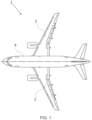
- FIG 1 shows an aircraft 1 with port and starboard wings 2, 3.
- Each wing has a cantilevered structure with a length extending in a generally spanwise direction 19 from a root to a tip (shown in Figure 3 ), the root being joined to an aircraft fuselage 4.
- the wings 2, 3 are similar in construction so only the starboard wing 3 will be described in detail with reference to Figures 2 and 3 .
- the main structural element of the wing 3 is a wing box 20 that may be formed by upper and lower covers 21, 22 and front and rear spars 6, 7 shown in cross-section in Figure 2 .
- the covers 21, 22 and spars 6, 7 may each be formed of Carbon Fibre Reinforced Polymer (CFRP) laminate components.
- Each cover 21, 22 comprises a panel assembly and may have a curved aerodynamic outer surface (e.g. the upper surface of the upper cover 21 and the lower surface of the lower cover 22) over which air flows during flight of the aircraft 1.
- Each cover 21, 22 has an inner surface carrying a series of stiffeners 8 extending in the spanwise direction 19 (only some of the stiffeners 8 are labelled so as to improve the clarity of the figures).
- Each stiffener 8 is joined to one cover 21, 22 but not the other.
- the wing box 20 has a plurality of transverse ribs, each rib being joined to the covers 21, 22 and the spars 6, 7.
- the ribs 10 may include an inner-most inboard rib 10a located at the root of the wing box 20, an outer-most outboard rib 10c at the tip of the wing box 20, and one or more mid-span ribs 10b between the inner-most and outer-most ribs 10a, 10c.
- the inner-most rib 10a may be an attachment rib which forms the root of the wing box 20 and is joined to a centre wing box 18 within the body of the fuselage 4.
- Each rib 10a, 10b, 10c may connect the upper cover 21 to the lower cover 22.
- the stiffeners 8 may pass through rib recesses (not shown) in the ribs 10b.
- Pipework 30 shown in Figure 4 extends through one of more of the wing ribs 10a, 10b, 10c, for example to convey fuel between an aircraft engine and a fuel tank, or between a refuelling coupler and a fuel tank.
- Figure 4 is a schematic cross-sectional view showing an aircraft pipework assembly comprising pipework 30 extending through the inboard rib 10a at the root of the wing 3, and a series of four of the mid-span ribs 10b.
- the pipework 30 passes through the plane of each rib 10a, 10b.
- the pipework 30 may pass through an aperture in each of the ribs 10a, 10b.
- the pipework 30 comprises a double-walled pipe assembly with an outer pipe 30a, and an inner pipe 30b within the outer pipe 30a.
- the inner pipe 30b is arranged to carry cryogenic fuel, such as liquid hydrogen. To maintain the cryogenic fuel at cryogenic temperatures, it is important to minimise thermal losses from the pipework 30. To achieve this, the interspace between the outer pipe 30a and the inner pipe 30b may be held at a vacuum pressure.
- Pipe spacers may be fitted between the outer pipe 30a and the inner pipe 30b to keep the outer and inner pipes 30a, 30b coaxial and transmit radial loads between them.
- the pipe spacers surround the inner pipe 30a and can be distributed at intervals along the length of the pipework 30.
- the pipework 30 is coupled to each rib 10a, 10b by a fixture arrangement 40a or 40b.
- the fixture arrangement 40a at the inboard rib 10a is configured to restrict translational movement of the pipework 30 in the longitudinal direction relative to the rib 10a, restrict translational movement of the pipework 30 in the plane of the rib 10a (i.e. radial movement away from a longitudinal axis of the pipework 30), and allow rotation of the pipework 30 relative to the rib 10a about the longitudinal axis.
- the fixture arrangement 40b at each mid-span rib 10b is configured to restrict translational movement of the pipework 30 in the plane of the rib 10b (i.e. radial movement away from a longitudinal axis of the pipework 30), but allows translational movement in the longitudinal direction (i.e. the direction of the longitudinal axis) and rotation about three perpendicular axes.
- the pipework 30 is simply supported by the fixture arrangements 40a, 40b such that shear loads are transmitted from the aircraft wing structure, through the ribs 10a, 10b, to the pipework 30, whilst bending loads are minimised or mitigated.
- This can be particularly important in cryogenic applications due to the increased thickness of the fuel pipes 30a, 30b generally required compared to fuel pipes in non-cryogenic applications.
- the fuel pipes 30a, 30b may be formed of relatively stiff materials such as metals, and for example stainless steel.
- the fixture arrangement 40a provides a 'master' axial pipe location, and all other fixture arrangements 40b support the pipework 30 radially but allow sliding in the axial direction, thus enabling the pipework 30 to expand/contract thermally.
- the fuel pipes 30a, 30b may be formed from a metal with a low thermal expansion coefficient to reduce such thermal expansion/contraction.
- the pipework 30 has a flange fitting 35a at its inboard end, which may be connected to further pipework (not shown) leading to a fuel tank system.
- the pipework 30 also has a flange fitting 35b at its outboard end, which may be connected to further pipework (not shown) leading to an engine of the aircraft, or to a refuel coupling or vent outlet.
- Figure 5-9 show an example of the fixture arrangement 40a at the inboard rib 10b.
- the ribs include an inner-most inboard rib 10a located at a root of the wing box, an outer-most outboard rib 10c at a tip of the wing box, and one or more mid-span ribs 10b between the inner-most and outer-most ribs.
- the fixture arrangement 40a is at the inboard rib 10b, but in other embodiments the fixture arrangement 40a may be at one or more of the mid-span ribs 10b.
- the fixture arrangement 40a comprises a spherical bearing between the pipework 30 and the aircraft structure (in this case, the rib 10a).
- a tie rod 50 is also provided, connecting the pipework 30 to the rib 10a.
- the spherical bearing comprises a ball mounted to the pipework 30, and a housing coupled to the rib 10a.
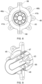
- the ball comprises an assembly of two ball parts 41a, 41b which are distributed around a circumference of the pipework as shown in Figure 8 .
- each ball part 41a, 41b comprises a projection 47 which fits into a recess 48 of the other ball part.
- the ball parts 41a, 41b may be metallic or GFRP (glass fibre reinforced plastic) materials - for example G10 GFRP or G11 GFRP.
- the ball parts 41a, 41b comprise a themoplastic material.
- the housing comprises an assembly of two housing parts 46a, 46b which are distributed around a circumference of the pipework.
- Each housing part 46a, 46b has lugs 49 which are attached to the rib 10a by fasteners 65, such as bolts, as shown in Figure 6 .
- Each housing part 46a, 46b also has a pair of lugs 58 which are attached to the lugs 58 of the other housing part by fasteners, such as bolts (not shown).
- Providing a two-part housing arrangement 46a, 46b enables a positive fit and location (both axially and radially), which is mechanically robust.
- the housing parts 46a, 46b may be metallic or GFRP (glass fibre reinforced plastic) materials - for example G10 GFRP or G11 GFRP.
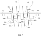
- housing parts 46a, 46b comprise a themoplastic material.
- the ball 41a, 41b comprises a convex spherical bearing surface 42a, 42b; and the housing 46a, 46b comprises a concave spherical bearing surface 51a, 51b which mates with the convex spherical bearing surface of the ball.
- the spherical bearing is configured to enable the pipework 30 to rotate relative to the rib 10a about three perpendicular axes, labelled X, Y, Z in Figure 9 .
- the pipework 30 is relatively rigid, and enabling rotation alleviates stresses induced into the pipework 30 as a result of wing flex during flight.
- the concave spherical bearing surface 51a, 51b of the housing contacts the convex spherical bearing surface 42a, 42b of the ball, providing a plain bearing with a sliding contact between the spherical bearing surfaces.
- Providing a two-part housing arrangement 46a, 46b enables a low (or zero) clearance between the spherical bearing surfaces to be achieved.
- the spherical bearing surfaces may have ball-bearings between them, so there is no direct contact between the spherical bearing surfaces.
- the fixture arrangement 40a is also configured to enable the pipework 30 to translate relative to the ball 41a, 41b in an axial direction aligned with a longitudinal axis 52 of the pipework 30.
- an axial bearing comprising an inner bearing surface 53a, 53b of the ball which mates with an outer surface of the pipework - in this case the outer surface of the outer pipe 30a.
- the inner bearing surface 53a, 53b of the ball and the outer surface of the outer pipe 30a are both cylindrical, although in other cases (for example where the cross-section of the outer pipe 30a is not circular) the shape may be different.
- the inner bearing surface 53a, 53b of the ball contacts the outer surface of the pipework, providing a plain bearing with a sliding contact between them.
- the bearing surfaces of the axial bearing may have ball-bearings between them, so there is no direct contact between them.
- the inner bearing surface 53a, 53b of the ball mates with an outer surface of the pipework 30, which in this example is a metallic outer surface of the outer pipe 30a.
- the outer surface of the pipework (which mates with the inner bearing surface 53a, 53b of the ball) may be provided by a sleeve which is fixed to the outer pipe 30a.
- a sleeve could be made of a low friction material such as a thermoplastic material.
- the rib 10a has a rib plane 55 which may pass through the convex spherical bearing surface 42a, 42b of the ball as shown in Figure 7 , and/or may also pass through the bearing surfaces of the axial bearing.
- the angle of the longitudinal axis 52 can vary. In Figure 4 the longitudinal axis 52 is perpendicular to the rib plane 55, but in Figures 5-7 it is inclined at an oblique angle to the rib plane 55.
- a first tie rod bearing 51 connects the tie rod 50 to the pipework 30, and a second tie rod bearing 52 connects the tie rod 50 to the rib 10a.
- the first tie rod bearing 51 is configured to enable the tie rod 50 to rotate relative to the pipework 30; and the second tie rod bearing 52 is configured to enable the tie rod 50 to rotate relative to the rib 10a.
- the tie rod 50 typically lies in a horizontal plane, in order to minimise bending of the pipework 30 relative to the wing rib 10a (note that bending of the wing occurs predominantly in the vertical plane).
- the axial bearing enables the pipework 30 to translate relative to the ball 41a, 41b in the axial direction, and this prevents the spherical bearing from reacting axial loads aligned with the axial direction. Instead, such axial loads are reacted by the tie rod 50. Since axial loads do not need to be reacted by the spherical bearing, the spherical bearing can be relatively light and narrow. Also, higher axial loads may be reacted by the tie rod 50 than could be reacted by the spherical bearing.
- the spherical bearing is configured to transmit radial load (i.e. load normal to the spherical bearing surfaces 42a, 42b, 51a, 51b) between the pipework 30 and the rib 10, but such radial load can be transmitted with a ball which is relatively narrow (in the radial sense).
- radial load i.e. load normal to the spherical bearing surfaces 42a, 42b, 51a, 51b
- the tie rod bearings 51, 52 may each be configured to enable the tie rod 50 to rotate about three perpendicular axes.
- the tie rod bearings 51, 52 have the same design, and only the components of the second tie rod bearing 52 are numbered in Figure 6 .
- Each tie rod bearing 51, 52 comprises a bracket 54 attached to the rib 10a or the pipework 30; a ball 55 carried by the bracket 54; and a pin 56 which is fixed to the tie rod 50 at one end and has a spherical socket 57 at the other end.
- the spherical socket 57 mates with the ball 55, providing a plain spherical bearing.
- the pipework 30 may include failsafe flanges 45 which are welded to the outer pipe 30a, one on either side of the rib 10a, with a gap between each failsafe flange 45 and the ball 41a, 41b (the gap may be 2mm for example).
- the gap may be 2mm for example.
- the failsafe flanges 45 prevent excessive axial loads being applied to the spherical bearing.
- the failsafe flanges 45 may also axially constrain the ball parts 41a, 41b which are otherwise free to slide along the pipework 30.
- the tie rod 50 extends along a tie rod axis 61 between the first tie rod bearing and the second tie rod bearing.
- the tie rod axis 61 extends at an acute angle ⁇ to the axial direction (i.e. the longitudinal axis 52 of the pipework).
- the acute angle ⁇ is as small as possible, optionally less than 30 degrees or less than 20 degrees or less than 10 degrees.
- the acute angle ⁇ may vary during flight by a small amount, due to rotation and/or translation of the pipework 30 which causes the tie rod 50 to rotate about one or both of the tie rod bearings 51, 52.
- Wing bending is predominantly in the vertical plane with fore and aft deflections being negligible. Therefore with the tie rod axis 61 in the horizontal plane in line with the longitudinal axis 52 of the pipework, the pipework 30 is allowed to freely rotate in the vertical plane. Depending on the angle ⁇ of the tie rod in relation to the pipework, the pipework will also slide by a very small distance in the ball as the pipework 30 bends and the tie rod rotates upwards, but either way the tie rod will only be reacting the axial loads (inertia and friction). The tie rod will react loads in both directions.
- the pipework passes through a hole 60 in the rib 10a.
- Figure 9 also shows the detail of a pipe spacer 43 which separates the inner and outer pipes 30a, 30b of the pipework 30.
- fixture arrangement 40a is relatively complex, it is only required at a single rib 10a, and enables relatively simple fixture arrangements 40b to be used at the other ribs 10b.
- the tie rod 50 provides an independent and separate load path (optionally with the failsafe flanges 45 as a waiting failsafe) with enhanced axial load reaction.
- the first tie rod bearing 51 is configured to enable the tie rod 50 to rotate relative to the pipework; and the second tie rod bearing 52 is configured to enable the tie rod 50 to rotate relative to the aircraft structure.
- the first tie rod bearing 51 is configured to enable the tie rod 51 to rotate relative to the pipework about three perpendicular axes, but in other embodiments it may be configured to enable the tie rod 51 to rotate relative to the pipework about only two perpendicular axes, or about only a single axis.
- the second tie rod bearing 52 is configured to enable the tie rod 51 to rotate relative to the aircraft structure about three perpendicular axes, but in other embodiments it may be configured to enable the tie rod 51 to rotate relative to the aircraft structure about only two perpendicular axes, or about only a single axis.
- pipework 30 in the present example is described as conveying liquid hydrogen, it will be appreciated that other fuels, and particularly cryogenic fuels, may be adopted.
- a gaseous hydrogen fuel may be used.
- an inert gas may replace the vacuum in the interspace between the outer pipe 30a and the inner pipe 30b.
- the pipework 30 in the present example comprises a double-walled pipe assembly.
- the pipework may comprise a single-walled pipe, a pipe assembly comprising a series of single-walled pipes coupled end-to-end, or any other arrangement of one or more pipes.
- the aircraft pipework assembly is installed in a wing 3 of the aircraft, but in other embodiments of the invention a similar aircraft pipework assembly may be provided in another part of the aircraft, such as the fuselage 4 or a fairing. In this case the fixture arrangement will fix the pipework to a different aircraft structure, such as a fuselage rib.
- embodiments of the present invention provide pipework coupled to an aircraft structure (such as a wing rib) by a fixture arrangement with a spherical bearing.
- a tie rod connects the pipework to the aircraft structure, via respective tie rod bearings.
- the fixture arrangement has an axial bearing which enables the pipework to translate relative to the spherical bearing in an axial direction aligned with a longitudinal axis of the pipework.
- the tie rod picks up axial load, rather than the spherical bearing, enabling the spherical bearing to be made more compact.
Landscapes
- Engineering & Computer Science (AREA)
- General Engineering & Computer Science (AREA)
- Aviation & Aerospace Engineering (AREA)
- Mechanical Engineering (AREA)
- Pivots And Pivotal Connections (AREA)
- Supports For Pipes And Cables (AREA)
- Support Of The Bearing (AREA)
Abstract
Description
- The present invention relates to an aircraft pipework assembly comprising an aircraft structure; pipework; and a fixture arrangement between the pipework and the aircraft structure. Typically, although not exclusively, the pipework may be for conveying liquid hydrogen.
- Liquid Hydrogen distribution system pipework is more complex than conventional kerosene pipework. To maintain the very low temperatures of liquid hydrogen (-253°C), the pipework is typically corrosion resistant steel (CRES), double walled and vacuum insulated. The resulting pipework is therefore more rigid than the kerosene equivalent.
- For long rigid pipework routed through a wing box, large stresses will be induced into the pipework under wing bending. The pipework may be locally restrained by conventional fixture arrangements such as saddle clamps, clamp blocks or p-clamps. These conventional fixture arrangements do not offer any axial load reaction.
- Hydrogen fuel lines typically span long distances across the aircraft wing between the fuel tanks and engines, or fuel tanks and refuel couplings, with the fuel lines expected to bend and twist in accordance with the bend and twist of the wing. The fuel lines attach to at least some of those ribs, presenting a need for fixture arrangements that minimise stress concentrations caused by over-constraint of the fuel lines.
- A first aspect of the invention provides an aircraft pipework assembly comprising: an aircraft structure; pipework; a fixture arrangement between the pipework and the aircraft structure; a tie rod; a first tie rod bearing which connects the tie rod to the pipework; and a second tie rod bearing which connects the tie rod to the aircraft structure; wherein the fixture arrangement comprises a spherical bearing, the spherical bearing comprising a ball mounted to the pipework and a housing coupled to the aircraft structure; the ball comprises a convex spherical bearing surface; the housing comprises a concave spherical bearing surface which mates with the convex spherical bearing surface of the ball; and the fixture arrangement is configured to enable the pipework to translate relative to the ball in an axial direction aligned with a longitudinal axis of the pipework.
- Optionally the spherical bearing is configured to enable the pipework to rotate relative to the aircraft structure about three perpendicular axes.
- Optionally the spherical bearing is configured to transmit radial load between the pipework and the aircraft structure, and the radial load is normal to the spherical bearing surfaces.
- Optionally the concave spherical bearing surface contacts the convex spherical bearing surface of the ball.
- Optionally the fixture arrangement further comprises an axial bearing, the axial bearing comprising an inner bearing surface of the ball which mates with an outer surface of the pipework, wherein the axial bearing is configured to enable the pipework to translate relative to the ball in the axial direction.
- Optionally the inner bearing surface of the ball contacts the outer surface of the pipework.
- Optionally the inner bearing surface of the ball and the outer surface of the pipework are both cylindrical.
- Optionally the first tie rod bearing is configured to enable the tie rod to rotate relative to the pipework about two or three perpendicular axes.
- Optionally the second tie rod bearing is configured to enable the tie rod to rotate relative to the aircraft structure about two or three perpendicular axes.
- Optionally the first tie rod bearing and/or the second tie rod bearing is a spherical bearing.
- Optionally the ball comprises an assembly of two or more ball parts which are distributed around a circumference of the pipework.
- Optionally the housing comprises an assembly of two or more housing parts which are distributed around a circumference of the pipework.
- Optionally the tie rod extends along a tie rod axis between the first tie rod bearing and the second tie rod bearing, and the tie rod axis extends at an acute angle to the axial direction.
- Optionally the acute angle is less than 30 degrees or less than 20 degrees or less than 10 degrees.
- Optionally the housing is attached to the aircraft structure by fasteners.
- Optionally the pipework comprises a pipe assembly, the pipe assembly comprising two or more pipe parts which are distributed in the axial direction and/or distributed radially orthogonal to the axial direction.
- Optionally the pipework comprises a double-walled pipe assembly, the double-walled pipe assembly comprising an inner pipe within an outer pipe.
- Optionally the pipework is configured to convey fuel, for example hydrogen.
- Optionally the pipework further comprises failsafe flanges, one on either side of the aircraft structure. Optionally one of the failsafe flanges is configured to come into contact with the aircraft structure in the event of failure of the tie rod and/or one of the failsafe flanges is configured to come into contact with the housing in the event of failure of the tie rod.
- A further aspect of the invention provides an aircraft wing comprising an aircraft pipework assembly according to the first aspect of the invention.
- Optionally the aircraft wing further comprises a wing box with upper and lower covers, and ribs joined to the upper and lower covers, wherein the aircraft structure is one of the ribs.
- Optionally the pipework passes through a hole in the one of the ribs.
- Optionally the one of the ribs has a rib plane which passes through one or both of the spherical bearing surfaces.
- Optionally the ribs include an inner-most rib located at a root of the wing box, an outer-most rib at a tip of the wing box, and one or more mid-span ribs between the inner-most and outer-most ribs; wherein the aircraft structure is the inner-most rib.
- A further aspect of the invention provides an aircraft wing comprising: a wing rib; pipework; a fixture arrangement between the pipework and the wing rib; and a tie rod connecting the pipework to the wing rib, wherein the fixture arrangement is configured to enable the pipework to rotate relative to the wing rib about three perpendicular axes; and the fixture arrangement is configured to enable the pipework to translate relative to the fixture arrangement in an axial direction aligned with a longitudinal axis of the pipework.
- Embodiments of the invention will now be described with reference to the accompanying drawings, in which:
-
Figure 1 shows an aircraft; -
Figure 2 is a sectional view of a wing box of the starboard wing; -
Figure 3 shows the wing box extending along a wing; -
Figure 4 shows an aircraft pipework assembly with pipework extending along the wing; -
Figure 5 shows a fixture arrangement coupling the pipework to an inboard wing rib; -
Figure 6 shows the fixture arrangement ofFigure 5 in cross-section; -
Figure 7 is an enlarged cross-sectional view showing the detail of the spherical bearing; -
Figure 8 is an end view of the fixture arrangement; and -
Figure 9 is an isometric view of the fixture arrangement, partially in section. -
Figure 1 shows anaircraft 1 with port andstarboard wings spanwise direction 19 from a root to a tip (shown inFigure 3 ), the root being joined to anaircraft fuselage 4. Thewings starboard wing 3 will be described in detail with reference toFigures 2 and 3 . - The main structural element of the
wing 3 is awing box 20 that may be formed by upper andlower covers rear spars Figure 2 . The covers 21, 22 andspars cover upper cover 21 and the lower surface of the lower cover 22) over which air flows during flight of theaircraft 1. Eachcover stiffeners 8 extending in the spanwise direction 19 (only some of thestiffeners 8 are labelled so as to improve the clarity of the figures). Eachstiffener 8 is joined to onecover - The
wing box 20 has a plurality of transverse ribs, each rib being joined to the covers 21, 22 and thespars inboard rib 10a located at the root of thewing box 20, anouter-most outboard rib 10c at the tip of thewing box 20, and one or moremid-span ribs 10b between the inner-most andouter-most ribs inner-most rib 10a may be an attachment rib which forms the root of thewing box 20 and is joined to acentre wing box 18 within the body of thefuselage 4. Eachrib upper cover 21 to thelower cover 22. Thestiffeners 8 may pass through rib recesses (not shown) in theribs 10b. -
Pipework 30 shown inFigure 4 extends through one of more of thewing ribs -
Figure 4 is a schematic cross-sectional view showing an aircraft pipeworkassembly comprising pipework 30 extending through theinboard rib 10a at the root of thewing 3, and a series of four of themid-span ribs 10b. In particular, thepipework 30 passes through the plane of eachrib pipework 30 may pass through an aperture in each of theribs - The
pipework 30 comprises a double-walled pipe assembly with anouter pipe 30a, and aninner pipe 30b within theouter pipe 30a. Theinner pipe 30b is arranged to carry cryogenic fuel, such as liquid hydrogen. To maintain the cryogenic fuel at cryogenic temperatures, it is important to minimise thermal losses from thepipework 30. To achieve this, the interspace between theouter pipe 30a and theinner pipe 30b may be held at a vacuum pressure. - Pipe spacers may be fitted between the
outer pipe 30a and theinner pipe 30b to keep the outer andinner pipes inner pipe 30a and can be distributed at intervals along the length of thepipework 30. - The
pipework 30 is coupled to eachrib fixture arrangement - The
fixture arrangement 40a at theinboard rib 10a is configured to restrict translational movement of thepipework 30 in the longitudinal direction relative to therib 10a, restrict translational movement of thepipework 30 in the plane of therib 10a (i.e. radial movement away from a longitudinal axis of the pipework 30), and allow rotation of thepipework 30 relative to therib 10a about the longitudinal axis. By restricting movement of thepipework 30 along the longitudinal axis at one or more points (in this case only theinboard rib 10a), thepipework 30 is prevented from sliding freely through thewing box 20. - The
fixture arrangement 40b at eachmid-span rib 10b is configured to restrict translational movement of thepipework 30 in the plane of therib 10b (i.e. radial movement away from a longitudinal axis of the pipework 30), but allows translational movement in the longitudinal direction (i.e. the direction of the longitudinal axis) and rotation about three perpendicular axes. - In this manner, the
pipework 30 is simply supported by thefixture arrangements ribs pipework 30, whilst bending loads are minimised or mitigated. This can be particularly important in cryogenic applications due to the increased thickness of thefuel pipes - The
fuel pipes - The
fixture arrangement 40a provides a 'master' axial pipe location, and allother fixture arrangements 40b support thepipework 30 radially but allow sliding in the axial direction, thus enabling thepipework 30 to expand/contract thermally. - Optionally the
fuel pipes - The
pipework 30 has a flange fitting 35a at its inboard end, which may be connected to further pipework (not shown) leading to a fuel tank system. - The
pipework 30 also has a flange fitting 35b at its outboard end, which may be connected to further pipework (not shown) leading to an engine of the aircraft, or to a refuel coupling or vent outlet. -
Figure 5-9 show an example of thefixture arrangement 40a at theinboard rib 10b. As noted above, the ribs include an inner-mostinboard rib 10a located at a root of the wing box, an outer-mostoutboard rib 10c at a tip of the wing box, and one or moremid-span ribs 10b between the inner-most and outer-most ribs. In this example, thefixture arrangement 40a is at theinboard rib 10b, but in other embodiments thefixture arrangement 40a may be at one or more of themid-span ribs 10b. - The
fixture arrangement 40a comprises a spherical bearing between thepipework 30 and the aircraft structure (in this case, therib 10a). Atie rod 50 is also provided, connecting thepipework 30 to therib 10a. - The spherical bearing comprises a ball mounted to the
pipework 30, and a housing coupled to therib 10a. - The ball comprises an assembly of two
ball parts Figure 8 . As shown inFigure 9 , eachball part projection 47 which fits into arecess 48 of the other ball part. - The
ball parts ball parts - As shown in
Figure 8 , the housing comprises an assembly of twohousing parts housing part lugs 49 which are attached to therib 10a byfasteners 65, such as bolts, as shown inFigure 6 . Eachhousing part lugs 58 which are attached to thelugs 58 of the other housing part by fasteners, such as bolts (not shown). - Providing a two-
part housing arrangement - The
housing parts Optionally housing parts - As shown in
Figure 7 , theball spherical bearing surface housing spherical bearing surface - The spherical bearing is configured to enable the
pipework 30 to rotate relative to therib 10a about three perpendicular axes, labelled X, Y, Z inFigure 9 . Thepipework 30 is relatively rigid, and enabling rotation alleviates stresses induced into thepipework 30 as a result of wing flex during flight. - In this case the concave
spherical bearing surface spherical bearing surface part housing arrangement - In an alternative embodiment, the spherical bearing surfaces may have ball-bearings between them, so there is no direct contact between the spherical bearing surfaces.
- The
fixture arrangement 40a is also configured to enable thepipework 30 to translate relative to theball longitudinal axis 52 of thepipework 30. - This translational freedom is provided by an axial bearing, the axial bearing comprising an
inner bearing surface outer pipe 30a. Theinner bearing surface outer pipe 30a are both cylindrical, although in other cases (for example where the cross-section of theouter pipe 30a is not circular) the shape may be different. - In this case the
inner bearing surface - The
inner bearing surface pipework 30, which in this example is a metallic outer surface of theouter pipe 30a. In an alternative embodiment the outer surface of the pipework (which mates with theinner bearing surface outer pipe 30a. Such a sleeve could be made of a low friction material such as a thermoplastic material. - The
rib 10a has arib plane 55 which may pass through the convexspherical bearing surface Figure 7 , and/or may also pass through the bearing surfaces of the axial bearing. - The angle of the
longitudinal axis 52 can vary. InFigure 4 thelongitudinal axis 52 is perpendicular to therib plane 55, but inFigures 5-7 it is inclined at an oblique angle to therib plane 55. - As shown in
Figure 5 , a firsttie rod bearing 51 connects thetie rod 50 to thepipework 30, and a secondtie rod bearing 52 connects thetie rod 50 to therib 10a. - The first
tie rod bearing 51 is configured to enable thetie rod 50 to rotate relative to thepipework 30; and the secondtie rod bearing 52 is configured to enable thetie rod 50 to rotate relative to therib 10a. - The
tie rod 50 typically lies in a horizontal plane, in order to minimise bending of thepipework 30 relative to thewing rib 10a (note that bending of the wing occurs predominantly in the vertical plane). - The axial bearing enables the
pipework 30 to translate relative to theball tie rod 50. Since axial loads do not need to be reacted by the spherical bearing, the spherical bearing can be relatively light and narrow. Also, higher axial loads may be reacted by thetie rod 50 than could be reacted by the spherical bearing. - The spherical bearing is configured to transmit radial load (i.e. load normal to the
spherical bearing surfaces pipework 30 and the rib 10, but such radial load can be transmitted with a ball which is relatively narrow (in the radial sense). - The
tie rod bearings tie rod 50 to rotate about three perpendicular axes. Thetie rod bearings tie rod bearing 52 are numbered inFigure 6 . - Each
tie rod bearing bracket 54 attached to therib 10a or thepipework 30; aball 55 carried by thebracket 54; and apin 56 which is fixed to thetie rod 50 at one end and has aspherical socket 57 at the other end. Thespherical socket 57 mates with theball 55, providing a plain spherical bearing. - The
pipework 30 may includefailsafe flanges 45 which are welded to theouter pipe 30a, one on either side of therib 10a, with a gap between eachfailsafe flange 45 and theball tie rod 50, then depending on the direction of the axial load either the outboard one of thefailsafe flange 45 will come into contact with therib 10a, or the inboardfailsafe flange 45 will come into contact with thehousing failsafe flanges 45 prevent excessive axial loads being applied to the spherical bearing. Thefailsafe flanges 45 may also axially constrain theball parts pipework 30. - As shown in
Figure 5 , thetie rod 50 extends along atie rod axis 61 between the first tie rod bearing and the second tie rod bearing. Thetie rod axis 61 extends at an acute angle θ to the axial direction (i.e. thelongitudinal axis 52 of the pipework). The acute angle θ is as small as possible, optionally less than 30 degrees or less than 20 degrees or less than 10 degrees. - The acute angle θ may vary during flight by a small amount, due to rotation and/or translation of the
pipework 30 which causes thetie rod 50 to rotate about one or both of thetie rod bearings - Wing bending is predominantly in the vertical plane with fore and aft deflections being negligible. Therefore with the
tie rod axis 61 in the horizontal plane in line with thelongitudinal axis 52 of the pipework, thepipework 30 is allowed to freely rotate in the vertical plane. Depending on the angle θ of the tie rod in relation to the pipework, the pipework will also slide by a very small distance in the ball as thepipework 30 bends and the tie rod rotates upwards, but either way the tie rod will only be reacting the axial loads (inertia and friction). The tie rod will react loads in both directions. - As shown in
Figure 9 , the pipework passes through ahole 60 in therib 10a. -
Figure 9 also shows the detail of apipe spacer 43 which separates the inner andouter pipes pipework 30. - Although the
fixture arrangement 40a is relatively complex, it is only required at asingle rib 10a, and enables relativelysimple fixture arrangements 40b to be used at theother ribs 10b. - The
tie rod 50 provides an independent and separate load path (optionally with thefailsafe flanges 45 as a waiting failsafe) with enhanced axial load reaction. - The first
tie rod bearing 51 is configured to enable thetie rod 50 to rotate relative to the pipework; and the secondtie rod bearing 52 is configured to enable thetie rod 50 to rotate relative to the aircraft structure. - In the embodiment of
Figures 1-9 , the firsttie rod bearing 51 is configured to enable thetie rod 51 to rotate relative to the pipework about three perpendicular axes, but in other embodiments it may be configured to enable thetie rod 51 to rotate relative to the pipework about only two perpendicular axes, or about only a single axis. - In the embodiment of
Figures 1-9 , the secondtie rod bearing 52 is configured to enable thetie rod 51 to rotate relative to the aircraft structure about three perpendicular axes, but in other embodiments it may be configured to enable thetie rod 51 to rotate relative to the aircraft structure about only two perpendicular axes, or about only a single axis. - Whilst the
pipework 30 in the present example is described as conveying liquid hydrogen, it will be appreciated that other fuels, and particularly cryogenic fuels, may be adopted. For example, a gaseous hydrogen fuel may be used. In this case, an inert gas may replace the vacuum in the interspace between theouter pipe 30a and theinner pipe 30b. - The
pipework 30 in the present example comprises a double-walled pipe assembly. In other embodiments of the invention, the pipework may comprise a single-walled pipe, a pipe assembly comprising a series of single-walled pipes coupled end-to-end, or any other arrangement of one or more pipes. - In the embodiment of
Figures 1-9 , the aircraft pipework assembly is installed in awing 3 of the aircraft, but in other embodiments of the invention a similar aircraft pipework assembly may be provided in another part of the aircraft, such as thefuselage 4 or a fairing. In this case the fixture arrangement will fix the pipework to a different aircraft structure, such as a fuselage rib. - In summary, embodiments of the present invention provide pipework coupled to an aircraft structure (such as a wing rib) by a fixture arrangement with a spherical bearing. A tie rod connects the pipework to the aircraft structure, via respective tie rod bearings. The fixture arrangement has an axial bearing which enables the pipework to translate relative to the spherical bearing in an axial direction aligned with a longitudinal axis of the pipework. The tie rod picks up axial load, rather than the spherical bearing, enabling the spherical bearing to be made more compact.
- Where the word 'or' appears this is to be construed to mean 'and/or' such that items referred to are not necessarily mutually exclusive and may be used in any appropriate combination.
- Although the invention has been described above with reference to one or more preferred embodiments, it will be appreciated that various changes or modifications may be made without departing from the scope of the invention as defined in the appended claims.
Claims (15)
- An aircraft pipework assembly comprising: an aircraft structure; pipework; a fixture arrangement between the pipework and the aircraft structure; a tie rod; a first tie rod bearing which connects the tie rod to the pipework; and a second tie rod bearing which connects the tie rod to the aircraft structure; wherein the fixture arrangement comprises a spherical bearing, the spherical bearing comprising a ball mounted to the pipework and a housing coupled to the aircraft structure; the ball comprises a convex spherical bearing surface; the housing comprises a concave spherical bearing surface which mates with the convex spherical bearing surface of the ball; and the fixture arrangement is configured to enable the pipework to translate relative to the ball in an axial direction aligned with a longitudinal axis of the pipework.
- An aircraft pipework assembly according to any preceding claim, wherein the spherical bearing is configured to enable the pipework to rotate relative to the aircraft structure about three perpendicular axes.
- An aircraft pipework assembly according to any preceding claim, wherein the spherical bearing is configured to transmit radial load between the pipework and the aircraft structure, and the radial load is normal to the spherical bearing surfaces.
- An aircraft pipework assembly according to any preceding claim, wherein the concave spherical bearing surface contacts the convex spherical bearing surface of the ball.
- An aircraft pipework assembly according to any preceding claim, wherein the fixture arrangement further comprises an axial bearing, the axial bearing comprising an inner bearing surface of the ball which mates with an outer surface of the pipework, and wherein the axial bearing is configured to enable the pipework to translate relative to the ball in the axial direction.
- An aircraft pipework assembly according to claim 5, wherein the inner bearing surface of the ball contacts the outer surface of the pipework.
- An aircraft pipework assembly according to any preceding claim, wherein the first tie rod bearing is configured to enable the tie rod to rotate relative to the pipework about two or three perpendicular axes.
- An aircraft pipework assembly according to any preceding claim, wherein the second tie rod bearing is configured to enable the tie rod to rotate relative to the aircraft structure about two or three perpendicular axes.
- An aircraft pipework assembly according to any preceding claim, wherein the ball comprises an assembly of two or more ball parts which are distributed around a circumference of the pipework.
- An aircraft pipework assembly according to any preceding claim, wherein the housing comprises an assembly of two or more housing parts which are distributed around a circumference of the pipework.
- An aircraft pipework assembly according to any preceding claim, wherein the tie rod extends along a tie rod axis between the first tie rod bearing and the second tie rod bearing, and the tie rod axis extends at an acute angle to the axial direction.
- An aircraft pipework assembly according to any preceding claim, wherein the pipework comprises a pipe assembly, the pipe assembly comprising two or more pipe parts which are distributed in the axial direction and/or distributed radially orthogonal to the axial direction.
- An aircraft pipework assembly according to any preceding claim, wherein the pipework comprises a double-walled pipe assembly, the double-walled pipe assembly comprising an inner pipe within an outer pipe.
- An aircraft wing comprising an aircraft pipework assembly according to any preceding claim.
- An aircraft wing according to claim 14, further comprising a wing box with upper and lower covers, and ribs joined to the upper and lower covers, wherein the aircraft structure is one of the ribs.
Applications Claiming Priority (1)
| Application Number | Priority Date | Filing Date | Title |
|---|---|---|---|
| GB2217744.8A GB2624684A (en) | 2022-11-25 | 2022-11-25 | Aircraft pipework assembly |
Publications (2)
| Publication Number | Publication Date |
|---|---|
| EP4375196A1 true EP4375196A1 (en) | 2024-05-29 |
| EP4375196B1 EP4375196B1 (en) | 2025-10-29 |
Family
ID=84889550
Family Applications (1)
| Application Number | Title | Priority Date | Filing Date |
|---|---|---|---|
| EP23211593.1A Active EP4375196B1 (en) | 2022-11-25 | 2023-11-22 | Aircraft pipework assembly |
Country Status (4)
| Country | Link |
|---|---|
| US (1) | US12449075B2 (en) |
| EP (1) | EP4375196B1 (en) |
| CN (1) | CN118083142A (en) |
| GB (1) | GB2624684A (en) |
Cited By (1)
| Publication number | Priority date | Publication date | Assignee | Title |
|---|---|---|---|---|
| WO2026073764A1 (en) * | 2024-10-01 | 2026-04-09 | Lufthansa Technik Ag | Aircraft having a refuelling connection for refuelling with a cryogenic fuel |
Families Citing this family (2)
| Publication number | Priority date | Publication date | Assignee | Title |
|---|---|---|---|---|
| EP4540136A1 (en) * | 2022-06-14 | 2025-04-23 | Airbus Operations Limited | An aircraft assembly |
| GB2624684A (en) * | 2022-11-25 | 2024-05-29 | Airbus Operations Ltd | Aircraft pipework assembly |
Citations (2)
| Publication number | Priority date | Publication date | Assignee | Title |
|---|---|---|---|---|
| US20100295293A1 (en) * | 2009-05-21 | 2010-11-25 | Airbus Operations Limited | Connector for a pipe |
| EP2634467A1 (en) * | 2010-10-26 | 2013-09-04 | Mitsubishi Heavy Industries, Ltd. | Pipe support structure for aircraft |
Family Cites Families (28)
| Publication number | Priority date | Publication date | Assignee | Title |
|---|---|---|---|---|
| US3695644A (en) * | 1970-03-30 | 1972-10-03 | Lockheed Aircraft Corp | Ball type flexible coupling for rigid conduits |
| US4676472A (en) * | 1985-12-09 | 1987-06-30 | Gerald Lapides | High voltage tubing conductor holding device |
| US5109321A (en) * | 1988-12-16 | 1992-04-28 | Mag Instrument, Inc. | Flashlight holder clamp assembly |
| IT1244025B (en) * | 1990-11-23 | 1994-06-28 | Tdi Tubi Dalmine Ilva Srl | GLASS COUPLING FOR METAL PIPES PARTICULARLY FOR FLUIDS |
| FR2787760B1 (en) * | 1998-12-29 | 2001-03-02 | Aerospatiale | AIRCRAFT LANDING GEAR, EQUIPPED WITH A DEVICE FOR PROTECTING A NEAR FUEL TANK, AND AIRCRAFT COMPRISING SUCH A TRAIN |
| US6220556B1 (en) * | 1999-05-28 | 2001-04-24 | Thomas M. Sohrt | Universally adjustable mounting system for switches, or the like |
| US6352227B1 (en) * | 2000-06-08 | 2002-03-05 | Clarence Eduard Hathaway | Segmented, ball jointed support |
| IL154578A (en) * | 2003-02-23 | 2008-12-29 | Plasson Ltd | Electrofusion coupling particularly useful for coupling plastic pipes |
| US7600791B2 (en) * | 2004-09-10 | 2009-10-13 | Emcon Technologies Llc | Exhaust system |
| DE102005047951B4 (en) | 2005-10-06 | 2010-12-23 | Man Diesel & Turbo Se | Sheathed pressure line |
| US20140361533A1 (en) * | 2009-06-15 | 2014-12-11 | Subsea Design A/S | Pipe connector |
| GB201113057D0 (en) * | 2011-07-29 | 2011-09-14 | Airbus Operations Ltd | Pipe connector |
| EP2610537B1 (en) * | 2011-12-28 | 2015-09-30 | Leo Dynamische Investering B.V. | Ball joint pipe connection |
| US20140110934A1 (en) * | 2012-10-22 | 2014-04-24 | Airgo Ip, Llc | Fluid-tight flexural joint |
| US9404607B2 (en) * | 2014-04-04 | 2016-08-02 | Caterpillar Global Mining Llc | Aftercooler pipe support assembly |
| US20150308597A1 (en) * | 2014-04-24 | 2015-10-29 | Brad Lillmars | Swiveling Plumbing Fitting |
| ES2957294T3 (en) * | 2017-04-04 | 2024-01-16 | Taimi R&D Inc | Support assembly to rotatably support hydraulic conduits |
| US10800540B2 (en) * | 2017-08-03 | 2020-10-13 | The Boeing Company | Transport element clamp system |
| US10597144B2 (en) * | 2017-12-01 | 2020-03-24 | Hadie Fotouhie | Under the wing-mounted jet engine with pivotal swivel joint to produce directional thrust vectoring thru swivel angle |
| WO2020009913A1 (en) * | 2018-07-05 | 2020-01-09 | Durr UNIVERSAL, Inc. | Expansion and movement joints |
| GB2576893A (en) | 2018-09-05 | 2020-03-11 | Airbus Operations Ltd | Pipe support |
| US11592123B2 (en) * | 2019-04-09 | 2023-02-28 | John HENNON | Slope adjusting and locking pipe hanger |
| GB2584882A (en) | 2019-06-19 | 2020-12-23 | Airbus Operations Ltd | Pipe support |
| US11623539B1 (en) * | 2020-06-19 | 2023-04-11 | Amazon Technologies, Inc. | Compliant joint with three degrees of freedom |
| FR3127203A1 (en) * | 2021-09-22 | 2023-03-24 | Airbus | AIRCRAFT COMPRISING A DIHYDROGEN TRANSPORT PIPE AND A BURIAL CHANNEL FOR SAID TRANSPORT PIPE |
| US20230175628A1 (en) * | 2021-12-07 | 2023-06-08 | Reelcraft Industries, Inc. | Hose stop |
| GB2624684A (en) * | 2022-11-25 | 2024-05-29 | Airbus Operations Ltd | Aircraft pipework assembly |
| EP4425028B1 (en) * | 2023-03-03 | 2025-05-07 | Airbus Operations GmbH | Coupling for a double-walled pipe with low heat ingress |
-
2022
- 2022-11-25 GB GB2217744.8A patent/GB2624684A/en active Pending
-
2023
- 2023-11-21 CN CN202311553956.XA patent/CN118083142A/en active Pending
- 2023-11-22 US US18/518,143 patent/US12449075B2/en active Active
- 2023-11-22 EP EP23211593.1A patent/EP4375196B1/en active Active
Patent Citations (2)
| Publication number | Priority date | Publication date | Assignee | Title |
|---|---|---|---|---|
| US20100295293A1 (en) * | 2009-05-21 | 2010-11-25 | Airbus Operations Limited | Connector for a pipe |
| EP2634467A1 (en) * | 2010-10-26 | 2013-09-04 | Mitsubishi Heavy Industries, Ltd. | Pipe support structure for aircraft |
Cited By (1)
| Publication number | Priority date | Publication date | Assignee | Title |
|---|---|---|---|---|
| WO2026073764A1 (en) * | 2024-10-01 | 2026-04-09 | Lufthansa Technik Ag | Aircraft having a refuelling connection for refuelling with a cryogenic fuel |
Also Published As
| Publication number | Publication date |
|---|---|
| GB2624684A (en) | 2024-05-29 |
| EP4375196B1 (en) | 2025-10-29 |
| US20240175527A1 (en) | 2024-05-30 |
| US12449075B2 (en) | 2025-10-21 |
| CN118083142A (en) | 2024-05-28 |
| GB202217744D0 (en) | 2023-01-11 |
Similar Documents
| Publication | Publication Date | Title |
|---|---|---|
| EP4375196B1 (en) | Aircraft pipework assembly | |
| US20250368348A1 (en) | An aircraft assembly | |
| US12296974B2 (en) | Aircraft | |
| US12337989B2 (en) | Cryogenic tank | |
| US8800917B2 (en) | Aircraft engine pylon AFT aerodynamic fairing | |
| US7887009B2 (en) | Methods and systems for attaching aircraft wings to fuselages | |
| US11130588B2 (en) | Wing assembly with fluid pipe | |
| EP4253253B1 (en) | An aircraft | |
| US12241577B2 (en) | Fluid pipe connection | |
| EP4375195B1 (en) | AIRCRAFT DEVICE | |
| US20240174373A1 (en) | Pipe spacer | |
| EP4728215A1 (en) | Pipe spacer | |
| EP4728216A1 (en) | Pipe spacer |
Legal Events
| Date | Code | Title | Description |
|---|---|---|---|
| PUAI | Public reference made under article 153(3) epc to a published international application that has entered the european phase |
Free format text: ORIGINAL CODE: 0009012 |
|
| STAA | Information on the status of an ep patent application or granted ep patent |
Free format text: STATUS: THE APPLICATION HAS BEEN PUBLISHED |
|
| AK | Designated contracting states |
Kind code of ref document: A1 Designated state(s): AL AT BE BG CH CY CZ DE DK EE ES FI FR GB GR HR HU IE IS IT LI LT LU LV MC ME MK MT NL NO PL PT RO RS SE SI SK SM TR |
|
| STAA | Information on the status of an ep patent application or granted ep patent |
Free format text: STATUS: REQUEST FOR EXAMINATION WAS MADE |
|
| 17P | Request for examination filed |
Effective date: 20241029 |
|
| RBV | Designated contracting states (corrected) |
Designated state(s): AL AT BE BG CH CY CZ DE DK EE ES FI FR GB GR HR HU IE IS IT LI LT LU LV MC ME MK MT NL NO PL PT RO RS SE SI SK SM TR |
|
| GRAP | Despatch of communication of intention to grant a patent |
Free format text: ORIGINAL CODE: EPIDOSNIGR1 |
|
| STAA | Information on the status of an ep patent application or granted ep patent |
Free format text: STATUS: GRANT OF PATENT IS INTENDED |
|
| INTG | Intention to grant announced |
Effective date: 20250221 |
|
| GRAJ | Information related to disapproval of communication of intention to grant by the applicant or resumption of examination proceedings by the epo deleted |
Free format text: ORIGINAL CODE: EPIDOSDIGR1 |
|
| STAA | Information on the status of an ep patent application or granted ep patent |
Free format text: STATUS: REQUEST FOR EXAMINATION WAS MADE |
|
| GRAP | Despatch of communication of intention to grant a patent |
Free format text: ORIGINAL CODE: EPIDOSNIGR1 |
|
| STAA | Information on the status of an ep patent application or granted ep patent |
Free format text: STATUS: GRANT OF PATENT IS INTENDED |
|
| INTC | Intention to grant announced (deleted) | ||
| INTG | Intention to grant announced |
Effective date: 20250606 |
|
| GRAS | Grant fee paid |
Free format text: ORIGINAL CODE: EPIDOSNIGR3 |
|
| GRAA | (expected) grant |
Free format text: ORIGINAL CODE: 0009210 |
|
| STAA | Information on the status of an ep patent application or granted ep patent |
Free format text: STATUS: THE PATENT HAS BEEN GRANTED |
|
| AK | Designated contracting states |
Kind code of ref document: B1 Designated state(s): AL AT BE BG CH CY CZ DE DK EE ES FI FR GB GR HR HU IE IS IT LI LT LU LV MC ME MK MT NL NO PL PT RO RS SE SI SK SM TR |
|
| REG | Reference to a national code |
Ref country code: CH Ref legal event code: F10 Free format text: ST27 STATUS EVENT CODE: U-0-0-F10-F00 (AS PROVIDED BY THE NATIONAL OFFICE) Effective date: 20251029 Ref country code: GB Ref legal event code: FG4D |
|
| REG | Reference to a national code |
Ref country code: IE Ref legal event code: FG4D |
|
| REG | Reference to a national code |
Ref country code: DE Ref legal event code: R096 Ref document number: 602023008016 Country of ref document: DE |
|
| PGFP | Annual fee paid to national office [announced via postgrant information from national office to epo] |
Ref country code: DE Payment date: 20251119 Year of fee payment: 3 |
|
| PGFP | Annual fee paid to national office [announced via postgrant information from national office to epo] |
Ref country code: AT Payment date: 20260113 Year of fee payment: 3 |
|
| PGFP | Annual fee paid to national office [announced via postgrant information from national office to epo] |
Ref country code: FR Payment date: 20251229 Year of fee payment: 3 |
|
| REG | Reference to a national code |
Ref country code: NL Ref legal event code: MP Effective date: 20251029 |
|
| PG25 | Lapsed in a contracting state [announced via postgrant information from national office to epo] |
Ref country code: ES Free format text: LAPSE BECAUSE OF FAILURE TO SUBMIT A TRANSLATION OF THE DESCRIPTION OR TO PAY THE FEE WITHIN THE PRESCRIBED TIME-LIMIT Effective date: 20251029 |
|
| REG | Reference to a national code |
Ref country code: LT Ref legal event code: MG9D |
|
| PG25 | Lapsed in a contracting state [announced via postgrant information from national office to epo] |
Ref country code: NO Free format text: LAPSE BECAUSE OF FAILURE TO SUBMIT A TRANSLATION OF THE DESCRIPTION OR TO PAY THE FEE WITHIN THE PRESCRIBED TIME-LIMIT Effective date: 20260129 |
|
| PG25 | Lapsed in a contracting state [announced via postgrant information from national office to epo] |
Ref country code: FI Free format text: LAPSE BECAUSE OF FAILURE TO SUBMIT A TRANSLATION OF THE DESCRIPTION OR TO PAY THE FEE WITHIN THE PRESCRIBED TIME-LIMIT Effective date: 20251029 Ref country code: AT Free format text: LAPSE BECAUSE OF FAILURE TO SUBMIT A TRANSLATION OF THE DESCRIPTION OR TO PAY THE FEE WITHIN THE PRESCRIBED TIME-LIMIT Effective date: 20251029 Ref country code: HR Free format text: LAPSE BECAUSE OF FAILURE TO SUBMIT A TRANSLATION OF THE DESCRIPTION OR TO PAY THE FEE WITHIN THE PRESCRIBED TIME-LIMIT Effective date: 20251029 |
|
| REG | Reference to a national code |
Ref country code: AT Ref legal event code: MK05 Ref document number: 1851338 Country of ref document: AT Kind code of ref document: T Effective date: 20251029 |
|
| PG25 | Lapsed in a contracting state [announced via postgrant information from national office to epo] |
Ref country code: NL Free format text: LAPSE BECAUSE OF FAILURE TO SUBMIT A TRANSLATION OF THE DESCRIPTION OR TO PAY THE FEE WITHIN THE PRESCRIBED TIME-LIMIT Effective date: 20251029 |
|
| PG25 | Lapsed in a contracting state [announced via postgrant information from national office to epo] |
Ref country code: RS Free format text: LAPSE BECAUSE OF FAILURE TO SUBMIT A TRANSLATION OF THE DESCRIPTION OR TO PAY THE FEE WITHIN THE PRESCRIBED TIME-LIMIT Effective date: 20260129 |
|
| PG25 | Lapsed in a contracting state [announced via postgrant information from national office to epo] |
Ref country code: IS Free format text: LAPSE BECAUSE OF FAILURE TO SUBMIT A TRANSLATION OF THE DESCRIPTION OR TO PAY THE FEE WITHIN THE PRESCRIBED TIME-LIMIT Effective date: 20260228 |
|
| PG25 | Lapsed in a contracting state [announced via postgrant information from national office to epo] |
Ref country code: PT Free format text: LAPSE BECAUSE OF FAILURE TO SUBMIT A TRANSLATION OF THE DESCRIPTION OR TO PAY THE FEE WITHIN THE PRESCRIBED TIME-LIMIT Effective date: 20260302 |
|
| PG25 | Lapsed in a contracting state [announced via postgrant information from national office to epo] |
Ref country code: PL Free format text: LAPSE BECAUSE OF FAILURE TO SUBMIT A TRANSLATION OF THE DESCRIPTION OR TO PAY THE FEE WITHIN THE PRESCRIBED TIME-LIMIT Effective date: 20251029 |
|
| PG25 | Lapsed in a contracting state [announced via postgrant information from national office to epo] |
Ref country code: LV Free format text: LAPSE BECAUSE OF FAILURE TO SUBMIT A TRANSLATION OF THE DESCRIPTION OR TO PAY THE FEE WITHIN THE PRESCRIBED TIME-LIMIT Effective date: 20251029 |
|
| PG25 | Lapsed in a contracting state [announced via postgrant information from national office to epo] |
Ref country code: BG Free format text: LAPSE BECAUSE OF FAILURE TO SUBMIT A TRANSLATION OF THE DESCRIPTION OR TO PAY THE FEE WITHIN THE PRESCRIBED TIME-LIMIT Effective date: 20251029 |