EP4375195A1 - Aircraft assembly - Google Patents
Aircraft assembly Download PDFInfo
- Publication number
- EP4375195A1 EP4375195A1 EP23211202.9A EP23211202A EP4375195A1 EP 4375195 A1 EP4375195 A1 EP 4375195A1 EP 23211202 A EP23211202 A EP 23211202A EP 4375195 A1 EP4375195 A1 EP 4375195A1
- Authority
- EP
- European Patent Office
- Prior art keywords
- fixture arrangement
- assembly
- pipe
- pipe assembly
- contact surface
- Prior art date
- Legal status (The legal status is an assumption and is not a legal conclusion. Google has not performed a legal analysis and makes no representation as to the accuracy of the status listed.)
- Granted
Links
Images




Classifications
-
- B—PERFORMING OPERATIONS; TRANSPORTING
- B64—AIRCRAFT; AVIATION; COSMONAUTICS
- B64D—EQUIPMENT FOR FITTING IN OR TO AIRCRAFT; FLIGHT SUITS; PARACHUTES; ARRANGEMENT OR MOUNTING OF POWER PLANTS OR PROPULSION TRANSMISSIONS IN AIRCRAFT
- B64D37/00—Arrangements in connection with fuel supply for power plant
- B64D37/005—Accessories not provided for in the groups B64D37/02 - B64D37/28
-
- F—MECHANICAL ENGINEERING; LIGHTING; HEATING; WEAPONS; BLASTING
- F16—ENGINEERING ELEMENTS AND UNITS; GENERAL MEASURES FOR PRODUCING AND MAINTAINING EFFECTIVE FUNCTIONING OF MACHINES OR INSTALLATIONS; THERMAL INSULATION IN GENERAL
- F16L—PIPES; JOINTS OR FITTINGS FOR PIPES; SUPPORTS FOR PIPES, CABLES OR PROTECTIVE TUBING; MEANS FOR THERMAL INSULATION IN GENERAL
- F16L39/00—Joints or fittings for double-walled or multi-channel pipes or pipe assemblies
- F16L39/04—Joints or fittings for double-walled or multi-channel pipes or pipe assemblies allowing adjustment or movement
-
- B—PERFORMING OPERATIONS; TRANSPORTING
- B64—AIRCRAFT; AVIATION; COSMONAUTICS
- B64D—EQUIPMENT FOR FITTING IN OR TO AIRCRAFT; FLIGHT SUITS; PARACHUTES; ARRANGEMENT OR MOUNTING OF POWER PLANTS OR PROPULSION TRANSMISSIONS IN AIRCRAFT
- B64D37/00—Arrangements in connection with fuel supply for power plant
- B64D37/30—Fuel systems for specific fuels
-
- B—PERFORMING OPERATIONS; TRANSPORTING
- B64—AIRCRAFT; AVIATION; COSMONAUTICS
- B64D—EQUIPMENT FOR FITTING IN OR TO AIRCRAFT; FLIGHT SUITS; PARACHUTES; ARRANGEMENT OR MOUNTING OF POWER PLANTS OR PROPULSION TRANSMISSIONS IN AIRCRAFT
- B64D37/00—Arrangements in connection with fuel supply for power plant
- B64D37/32—Safety measures not otherwise provided for, e.g. preventing explosive conditions
-
- F—MECHANICAL ENGINEERING; LIGHTING; HEATING; WEAPONS; BLASTING
- F16—ENGINEERING ELEMENTS AND UNITS; GENERAL MEASURES FOR PRODUCING AND MAINTAINING EFFECTIVE FUNCTIONING OF MACHINES OR INSTALLATIONS; THERMAL INSULATION IN GENERAL
- F16L—PIPES; JOINTS OR FITTINGS FOR PIPES; SUPPORTS FOR PIPES, CABLES OR PROTECTIVE TUBING; MEANS FOR THERMAL INSULATION IN GENERAL
- F16L3/00—Supports for pipes, cables or protective tubing, e.g. hangers, holders, clamps, cleats, clips, brackets
- F16L3/08—Supports for pipes, cables or protective tubing, e.g. hangers, holders, clamps, cleats, clips, brackets substantially surrounding the pipe, cable or protective tubing
- F16L3/10—Supports for pipes, cables or protective tubing, e.g. hangers, holders, clamps, cleats, clips, brackets substantially surrounding the pipe, cable or protective tubing divided, i.e. with two members engaging the pipe, cable or protective tubing
-
- F—MECHANICAL ENGINEERING; LIGHTING; HEATING; WEAPONS; BLASTING
- F16—ENGINEERING ELEMENTS AND UNITS; GENERAL MEASURES FOR PRODUCING AND MAINTAINING EFFECTIVE FUNCTIONING OF MACHINES OR INSTALLATIONS; THERMAL INSULATION IN GENERAL
- F16L—PIPES; JOINTS OR FITTINGS FOR PIPES; SUPPORTS FOR PIPES, CABLES OR PROTECTIVE TUBING; MEANS FOR THERMAL INSULATION IN GENERAL
- F16L3/00—Supports for pipes, cables or protective tubing, e.g. hangers, holders, clamps, cleats, clips, brackets
- F16L3/16—Supports for pipes, cables or protective tubing, e.g. hangers, holders, clamps, cleats, clips, brackets with special provision allowing movement of the pipe
-
- F—MECHANICAL ENGINEERING; LIGHTING; HEATING; WEAPONS; BLASTING
- F16—ENGINEERING ELEMENTS AND UNITS; GENERAL MEASURES FOR PRODUCING AND MAINTAINING EFFECTIVE FUNCTIONING OF MACHINES OR INSTALLATIONS; THERMAL INSULATION IN GENERAL
- F16L—PIPES; JOINTS OR FITTINGS FOR PIPES; SUPPORTS FOR PIPES, CABLES OR PROTECTIVE TUBING; MEANS FOR THERMAL INSULATION IN GENERAL
- F16L3/00—Supports for pipes, cables or protective tubing, e.g. hangers, holders, clamps, cleats, clips, brackets
- F16L3/16—Supports for pipes, cables or protective tubing, e.g. hangers, holders, clamps, cleats, clips, brackets with special provision allowing movement of the pipe
- F16L3/20—Supports for pipes, cables or protective tubing, e.g. hangers, holders, clamps, cleats, clips, brackets with special provision allowing movement of the pipe allowing movement in transverse direction
- F16L3/202—Supports for pipes, cables or protective tubing, e.g. hangers, holders, clamps, cleats, clips, brackets with special provision allowing movement of the pipe allowing movement in transverse direction the transverse movement being converted to a rotational movement
-
- F—MECHANICAL ENGINEERING; LIGHTING; HEATING; WEAPONS; BLASTING
- F16—ENGINEERING ELEMENTS AND UNITS; GENERAL MEASURES FOR PRODUCING AND MAINTAINING EFFECTIVE FUNCTIONING OF MACHINES OR INSTALLATIONS; THERMAL INSULATION IN GENERAL
- F16L—PIPES; JOINTS OR FITTINGS FOR PIPES; SUPPORTS FOR PIPES, CABLES OR PROTECTIVE TUBING; MEANS FOR THERMAL INSULATION IN GENERAL
- F16L39/00—Joints or fittings for double-walled or multi-channel pipes or pipe assemblies
-
- F—MECHANICAL ENGINEERING; LIGHTING; HEATING; WEAPONS; BLASTING
- F16—ENGINEERING ELEMENTS AND UNITS; GENERAL MEASURES FOR PRODUCING AND MAINTAINING EFFECTIVE FUNCTIONING OF MACHINES OR INSTALLATIONS; THERMAL INSULATION IN GENERAL
- F16L—PIPES; JOINTS OR FITTINGS FOR PIPES; SUPPORTS FOR PIPES, CABLES OR PROTECTIVE TUBING; MEANS FOR THERMAL INSULATION IN GENERAL
- F16L5/00—Devices for use where pipes, cables or protective tubing pass through walls or partitions
-
- F—MECHANICAL ENGINEERING; LIGHTING; HEATING; WEAPONS; BLASTING
- F16—ENGINEERING ELEMENTS AND UNITS; GENERAL MEASURES FOR PRODUCING AND MAINTAINING EFFECTIVE FUNCTIONING OF MACHINES OR INSTALLATIONS; THERMAL INSULATION IN GENERAL
- F16L—PIPES; JOINTS OR FITTINGS FOR PIPES; SUPPORTS FOR PIPES, CABLES OR PROTECTIVE TUBING; MEANS FOR THERMAL INSULATION IN GENERAL
- F16L5/00—Devices for use where pipes, cables or protective tubing pass through walls or partitions
- F16L5/02—Sealing
- F16L5/025—Sealing the pipe being movable
-
- F—MECHANICAL ENGINEERING; LIGHTING; HEATING; WEAPONS; BLASTING
- F16—ENGINEERING ELEMENTS AND UNITS; GENERAL MEASURES FOR PRODUCING AND MAINTAINING EFFECTIVE FUNCTIONING OF MACHINES OR INSTALLATIONS; THERMAL INSULATION IN GENERAL
- F16L—PIPES; JOINTS OR FITTINGS FOR PIPES; SUPPORTS FOR PIPES, CABLES OR PROTECTIVE TUBING; MEANS FOR THERMAL INSULATION IN GENERAL
- F16L5/00—Devices for use where pipes, cables or protective tubing pass through walls or partitions
- F16L5/02—Sealing
- F16L5/14—Sealing for double-walled or multi-channel pipes
-
- F—MECHANICAL ENGINEERING; LIGHTING; HEATING; WEAPONS; BLASTING
- F16—ENGINEERING ELEMENTS AND UNITS; GENERAL MEASURES FOR PRODUCING AND MAINTAINING EFFECTIVE FUNCTIONING OF MACHINES OR INSTALLATIONS; THERMAL INSULATION IN GENERAL
- F16L—PIPES; JOINTS OR FITTINGS FOR PIPES; SUPPORTS FOR PIPES, CABLES OR PROTECTIVE TUBING; MEANS FOR THERMAL INSULATION IN GENERAL
- F16L59/00—Thermal insulation in general
- F16L59/06—Arrangements using an air layer or vacuum
- F16L59/065—Arrangements using an air layer or vacuum using vacuum
-
- F—MECHANICAL ENGINEERING; LIGHTING; HEATING; WEAPONS; BLASTING
- F16—ENGINEERING ELEMENTS AND UNITS; GENERAL MEASURES FOR PRODUCING AND MAINTAINING EFFECTIVE FUNCTIONING OF MACHINES OR INSTALLATIONS; THERMAL INSULATION IN GENERAL
- F16L—PIPES; JOINTS OR FITTINGS FOR PIPES; SUPPORTS FOR PIPES, CABLES OR PROTECTIVE TUBING; MEANS FOR THERMAL INSULATION IN GENERAL
- F16L59/00—Thermal insulation in general
- F16L59/14—Arrangements for the insulation of pipes or pipe systems
- F16L59/16—Arrangements specially adapted to local requirements at flanges, junctions, valves or the like
Definitions
- the present invention relates to an aircraft assembly comprising a pipe assembly rotatable relative to a fixture arrangement of the an aircraft structure, and an aircraft comprising the aircraft assembly.
- Hydrogen fuel lines are typically double-walled, with the interspace between the inner and outer pipes maintained at vacuum pressure in order to reduce thermal transfer between the fuel and atmosphere, and thereby maintain the cryogenic temperature of the fuel.
- Hydrogen fuel lines are generally quite thick and typically span long distances across the aircraft wing between the fuel tanks and engines, or fuel tanks and refuel couplings, with the fuel lines expected to bend and twist in accordance with the bend and twist of the wing.
- the fuel lines attach to at least some of those ribs, presenting a need for fixture arrangements that minimise stress concentrations caused by over-constraint of the fuel lines.
- a first aspect of the invention provides an aircraft assembly comprising: an aircraft structure; a pipe assembly; a fixture arrangement attached to the aircraft structure, the fixture arrangement contacting the pipe assembly via a curved bearing surface having curvature in two orthogonal directions; the curved bearing surface configured to enable the pipe assembly to rotate relative to the fixture arrangement about three perpendicular axes; wherein the pipe assembly comprises a stop member adjacent the fixture arrangement, a contact surface of the stop member configured to abut a contact surface of the fixture arrangement so as to restrict axial movement of the pipe assembly relative to the fixture arrangement, and wherein a distance between the contact surface of the fixture arrangement and the contact surface of the stop member increases radially from the longitudinal pipe axis.
- the distance between the contact surface of the fixture arrangement and the contact surface of the stop member may increase exponentially. This allows the arrangement to better account for the rotation of the pipe assembly relative to the fixture arrangement, maintaining more consistent contact therebetween so as to reduce stress concentrations.
- the contact surface of the stop member may be angled relative to a plane normal to the longitudinal pipe axis. This allows the fixture arrangement to adopt a contact surface parallel to the plane of the aircraft structure, and thereby permits a more direct load path through the fixture arrangement whilst minimising stress concentrations.
- the contact surface of the fixture arrangement may lie on a plane normal to the longitudinal pipe axis. With this arrangement, a more direct load path is provided through the fixture arrangement to the pipe assembly.
- the contact surface of the stop member may be curved in two orthogonal directions. This allows the contact surface of the stop member to better account for the rotation of the pipe assembly relative to the fixture arrangement, maintaining more consistent contact therebetween so as to reduce stress concentrations.
- a curvature of the curved bearing surface may match a curvature of the contact surface of the stop member. This allows contact to be made consistently as the pipe assembly is rotated relative to the fixture arrangement.
- the curved bearing surface may be on the fixture arrangement. This can allow rotation of the pipe assembly relative to the fixture arrangement.
- the curved bearing surface may contact a cylindrical bearing surface of the pipe assembly. This maintains a simple construction of the pipe assembly, whilst minimising contact with the fixture arrangement when in combination with a curved bearing surface on the fixture arrangement.
- the stop member may be formed of two or more parts that interconnect circumferentially. This provides an easier means of assembling the stop member, for example after assembly of the rest of the pipe assembly into the aircraft assembly.
- the pipe assembly may comprise a second stop member adjacent the fixture arrangement such that the fixture arrangement is between the first and second stop members, wherein a contact surface of the second stop member is configured to abut a second contact surface of the fixture arrangement so as to restrict axial movement of the pipe assembly relative to the fixture arrangement, and wherein a distance between the contact surface of the fixture arrangement and the contact surface of the second stop member increases radially from the longitudinal pipe axis.
- This provides restricted axial movement of the pipe assembly in both directions along the axis of the pipe assembly.
- the pipe assembly may have a plane of symmetry that lies between the first and second stop members. This provides a simple construction that can provide the same restriction on movement at either end.
- the first and second stop members may be connected by a collar, and wherein the collar contacts the fixture arrangement at the curved bearing surface. This allows the first and second stop members to be manufactured and assembled together.
- the axial movement of the pipe assembly relative to the fixture arrangement will be set depending on manufacturing tolerances and thermal effects.
- the axial movement of the pipe assembly relative to the fixture arrangement may be restricted by the first and second stop members with axial movement no greater than 10mm, or no greater than 5mm.
- the axial movement of the pipe assembly relative to the fixture arrangement may be restricted by the first and second stop members with axial movement of at least 2 mm.
- the pipe assembly may comprise an inner pipe within an outer pipe.
- the aircraft assembly may comprise a cryogenic fuel in the inner pipe.
- Thermal contraction can be a particular issue when dealing with cryogenic fuels, particularly as the pipes are generally thicker and thereby increase the rigidity of the pipes, as well as the disparity of temperatures acting on the inner and outer pipes.
- the cryogenic fuel may be liquid hydrogen.
- the aircraft assembly may comprise a vacuum pressure between the inner pipe and the outer pipe.
- a further aspect of the invention provides an aircraft comprising the aircraft structure of the first aspect.
- the aircraft structure may be a wing rib, fairing rib, or fuselage frame.
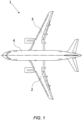
- FIG 1 shows an aircraft 1 with port and starboard wings 2, 3.
- Each wing has a cantilevered structure with a length extending in a generally spanwise direction 19 from a root to a tip (shown in Figure 3 ), the root being joined to an aircraft fuselage 4.
- the wings 2, 3 are similar in construction so only the starboard wing 3 will be described in detail with reference to Figures 2 and 3 .
- the main structural element of the wing 3 is a wing box 20 that may be formed by upper and lower covers 21, 22 and front and rear spars 6, 7 shown in cross-section in Figure 2 .
- the covers 21, 22 and spars 6, 7 may each be formed of Carbon Fibre Reinforced Polymer (CFRP) laminate components.
- Each cover 21, 22 comprises a panel assembly and may have a curved aerodynamic outer surface (e.g. the upper surface of the upper cover 21 and the lower surface of the lower cover 22) over which air flows during flight of the aircraft 1.
- Each cover 21, 22 has an inner surface carrying a series of stiffeners 8 extending in the spanwise direction 19 (only some of the stiffeners 8 are labelled so as to improve the clarity of the figures).
- Each stiffener 8 is joined to one cover 21, 22 but not the other.
- the wing box 20 has a plurality of transverse ribs, each rib being joined to the covers 21, 22 and the spars 6, 7.
- the ribs 10 may include an inner-most inboard rib 10a located at the root of the wing box 20, an outer-most rib 10c at the tip of the wing box 20, and one or more mid-span ribs 10b between the inner-most and outer-most ribs 10a, 10c.
- the inner-most rib 10a may be an attachment rib which forms the root of the wing box 20 and is joined to a centre wing box 18 within the body of the fuselage 4.
- Each rib 10a, 10b, 10c may connect the upper cover 21 to the lower cover 22.
- the stiffeners 8 may pass through rib recesses (not shown) in the ribs 10b.
- a pipe assembly 30 extends through one of more of the wing ribs 10a, 10b, 10c, for example between an aircraft engine and a fuel tank, or a refuelling coupler and the fuel tank.
- the pipe assembly 30 extends in a generally spanwise direction between the root of the wing 3 to the tip of the wing 3.
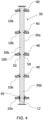
- Figure 4 is a schematic cross-sectional view showing the pipe assembly 30 extending through the inboard rib 10a at the root of the wing 3, and a series of four of the mid-span ribs 10b.
- the pipe assembly 30 passes through the plane of each rib 10a, 10b.
- the pipe assembly 30 may pass through an aperture (not shown) in each of the ribs 10a, 10b.
- the pipe assembly 30 is double-walled with an outer pipe 30a and an inner pipe 30b enveloped by the outer pipe 30a.
- the pipes 30a, 3b are preferably formed of a material with low thermal expansion coefficient, such as stainless steel.
- the inner pipe 30b is arranged to carry cryogenic fuels, such as liquid hydrogen. To maintain the cryogenic fuel at the required low temperatures, it is important to minimise thermal losses from the pipe assembly 30. To achieve this, the interspace between the outer pipe 30a and the inner pipe 30b may be held at a vacuum pressure.
- Pipe spacers 50 are fitted between the outer pipe 30a and the inner pipe 30b to keep the outer and inner pipes 30a, 30b coaxial and transmit radial loads between them, and are generally distributed at intervals along the length of the pipe assembly 30.
- the pipe assembly 30 is coupled to each rib 10a, 10b by a fixture arrangement 40.
- the fixture arrangement 40 associated with the inboard rib 10a is configured to restrict translational movement of the pipe assembly 30 in the longitudinal direction relative to the rib 10a, restrict translational movement of the pipe assembly 30 in the plane of the rib 10a (i.e. radial movement from a longitudinal axis 12 of the pipe assembly 30), and allow rotation of the pipe assembly 30 relative to the rib 10a about the longitudinal axis 12.
- the fixture arrangements 40 associated with the mid-span ribs 10b is configured to restrict translational movement of the pipe assembly 30 in the plane of the rib 10b (i.e. radial movement from a longitudinal axis 12 of the pipe assembly 30), but allows translational movement in the longitudinal direction (i.e. the direction of the longitudinal axis 12a) and rotation about three perpendicular axes.
- the pipe assembly 30 is simply supported by the fixture arrangements 40 such that shear loads are transmitted from the aircraft wing structure, through the ribs 10a, 10b, to the pipe assembly 30, whilst bending loads are minimised or mitigated.
- This can be particularly important in cryogenic application due to the increased thickness of the fuel pipes 30a, 30b generally required compared to fuel pipes in non-cryogenic applications.
- These fuel pipes 30a, 30b may be formed of relatively stiff materials such as metals, and for example stainless steel.
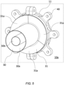
- Figure 5 shows the pipe assembly 30 attached to the inboard rib 10a by a fixture arrangement 40.
- the pipe assembly 30 may extend through a hole 11 in the rib 10a (as shown) or extend adjacent to the rib 10a.
- the fixture arrangement 40 is configured to restrict translational movement of the pipe assembly 30 in the longitudinal direction relative to the rib 10a in combination with an stopper element 31 (that will be discussed in further detail below), restrict translational movement of the pipe assembly 30 in the plane of the rib 10a (i.e.
- each fixture arrangement 40 may comprise a pair of generally C-shaped parts 41 that are brought together around the pipe assembly 30 to provide minimal contact that allows the pipe assembly 30 to slide, or at least lightly grip the outer pipe 30a.
- Each of the generally C-shaped parts 41 has an internal face 42 that faces the pipe assembly 30(See Figure 8 ).
- This collar 38 is itself fixedly attached to the outer pipe 30a.
- Each internal face 42 is rounded in the spanwise direction, such that the fixture arrangement 40 contacts the pipe assembly 30 via a curved bearing surface 42a having curvature in two orthogonal directions.
- the curved bearing surface 42a contacts a cylindrical bearing surface 36 of the pipe assembly 30 (See Figure 8 )
- the curved bearing surface 42a provides freedom for the pipe assembly 30 to rotate relative to the fixture arrangement 40 about three perpendicular axes.
- the bearing surface 36 of the pipe assembly 30 is able to roll across the curved bearing surface 42a of the fixture arrangement 40. This helps to accommodate bending and/or twisting of the wing 3.
- Each part 41 of the fixture arrangement 40 is formed with a low-friction material. Whilst the bearing surfaces 36, 42a are arranged in rolling contact, at least some sliding contact may occur.
- the low-friction material enables the pipe assembly 30 to move with a low-friction sliding interaction against the internal face 42 of the fixture arrangement 40. This further helps to accommodate bending and/or twisting of the wing 3 by minimising the loads transmitted into the inboard rib 10a.
- the collar 38 extends between first and second stop members 32, 33 to form a generally C-shaped stopper element 31, with the fixture arrangement 40 therebetween.
- the stopper element 31 may be integrally formed.
- the collar 38 is fixedly attached to the outer pipe 30a, with the stop members 32, 33, in the form of flanges, configured to restrict axial movement of the pipe assembly 30 relative to the fixture arrangement 40.
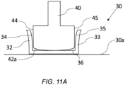
- a contact surface 34 of the first stop member 32 abuts a first contact surface 44 of the fixture arrangement 40 and a contact surface 35 of the second stop member 33 abuts a second contact surface 45 of the fixture arrangement 40.
- the collar 38 is symmetrical about a central plane, such that the pipe assembly 30 has a plane of symmetry that lies between the first and second stop members 32, 33.
- the stop members 32, 33 provide a simple, compact and lightweight solution to restricting axial movement of the pipe assembly 30 relative to the fixture arrangement 40 whilst allowing relative rotation between the pipe assembly 30 and the fixture arrangement 40.
- the arrangement may be designed to provide for any suitable limit of permitted relative rotation between the pipe assembly 30 and the fixture arrangement 40, although generally the rotation is less than 5 degrees or less than 3 degrees. This maintains the compact size of the arrangement whilst allowing sufficient relative rotation to take into account the bending strains of the wing 3.
- the stopper element 31 may be formed of a plurality of parts 31a that are arranged circumferentially.
- the parts 31a of the member 31 each contact a respective portion of the circumference of the outer pipe 30a. This segmentation provides redundancy in the event of failure of one of the parts 31a.
- the distance between the contact surfaces 44, 45 of the fixture arrangement 40 and the respective contact surfaces 34, 35 of the stop members 32, 33 increases radially from the longitudinal axis 12 of the pipe assembly 30.
- the distance between the first contact surface 44 of the fixture arrangement 40 and the contact surface 34 of the first stop member 32 increases radially from the longitudinal axis 12 of the pipe assembly 30, and the distance between the second contact surface 45 of the fixture arrangement 40 and the contact surface 35 of the second stop member 32 increases radially from the longitudinal axis 12 of the pipe assembly 30.
- the pipe assembly 30 is able to rotate about an axis perpendicular to the longitudinal pipe axis 12 whilst simultaneously restricting lateral movement of the pipe assembly 30 along the longitudinal axis 12 of the pipe assembly 30.
- the contact surfaces 34, 35 of the stop members 32, 33 are angled relative to a plane normal to the longitudinal pipe axis 12, whilst the contact surfaces 44, 45 of the fixture arrangement 40 lie on a plane normal to the longitudinal pipe axis 12.
- the contact surfaces 44, 45 of the fixture arrangement 40 may be angled relative to a plane normal to the longitudinal pipe axis 12.
- the advantage of only angling the contact surfaces 34, 35 of the stop members 32, 33 rather than the contact surfaces 44, 45 of the fixture arrangement 40, is that the complexity of the fixture arrangement 40 can be reduced, thereby reducing stress concentrations on a fixture arrangement 40.
- the fixture arrangement 40 is intended to carry the majority of the loads between the pipe assembly 30 and the rib 10a.
- the stop members 32, 33 primarily carries axial loads, i.e. loads along the longitudinal axis 12 of the pipe assembly 30.
- FIGS 11a-11C An example of the rotation of the pipe assembly 30 is shown in Figures 11a-11C , which show the pipe assembly 30 rotated into three different configurations relative to the fixture arrangement 40 whilst maintaining the general longitudinal position of the pipe assembly 30 relative to the fixture arrangement 40.
- the distance between the contact surfaces 44, 45 of the fixture arrangement 40 and the contact surfaces 34, 35 of the stop members 32, 33 increases exponentially, with each contact surface 34, 35 of the stop members 32, 33 curved in two orthogonal directions.
- the exponential increase of the distance can allow contact between the respective contact surfaces 34, 34, 44, 45 to be maintained as the pipe assembly 30 is rotated relative to the fixture arrangement 40 whilst minimising stress concentrations that might otherwise occur if the contact surfaces 34, 35 were planar.
- the curvature of the curved bearing surface 42a may match the curvature of the contact surfaces 34, 35 of the stop members 32, 33.
- the radius of curvature of the curved bearing surface 42a and the contact surfaces 34, 35 of the stop members 32, 33 may be the same.
- the fixture arrangement 40 and stop members 32, 33 may be arranged so as to provide at least some relative play therebetween, which can be set depending on manufacturing tolerances and thermal effects, although generally axial movement of the pipe assembly 30 relative to the fixture arrangement 40 will be restricted by the first and second stop members 32, 33 such that axial movement is no greater than 10mm, and preferably no greater than 5mm.
- the fixture arrangement 40 and stop members 32, 33 may be arranged so as to provide at least 2mm, and optionally 4mm of axial movement.
- the fixture arrangement 40 is described as having a curved bearing surface 42a that contacts a cylindrical bearing surface 36 of the pipe assembly 30, however it will be appreciated that the bearing surface 36 of the pipe assembly 30 may be curved whilst the bearing surface 42a of the fixture arrangement 40 is cylindrical.
- the combination of cylindrical and curved bearing surfaces minimises the contact area between the fixture arrangement 40 and pipe assembly 30, thereby reducing thermal transfer.
- an exclusively sliding contact may be formed between the pipe assembly 30 and the fixture arrangement 40 by providing respective bearing surfaces 36, 42a that are correspondingly curved.
- the stop members 32, 33 are described as part of a stopper element 31 that also includes a collar 38, with that collar 38 forming the bearing surface 36 of the pipe assembly 30.
- the pipe assembly 30 may not include a collar 38, such that the bearing surface 36 is formed on the outer pipe 30a.
- the pipe assembly 30 may include a single stop member 32, 33 in some examples, particularly those examples in which the axial restriction of the pipe assembly 30 relative to the fixture arrangement 40 is not of concern.
Landscapes
- Engineering & Computer Science (AREA)
- General Engineering & Computer Science (AREA)
- Mechanical Engineering (AREA)
- Aviation & Aerospace Engineering (AREA)
- Supports For Pipes And Cables (AREA)
- Tires In General (AREA)
Abstract
Description
- The present invention relates to an aircraft assembly comprising a pipe assembly rotatable relative to a fixture arrangement of the an aircraft structure, and an aircraft comprising the aircraft assembly.
- Hydrogen fuel lines are typically double-walled, with the interspace between the inner and outer pipes maintained at vacuum pressure in order to reduce thermal transfer between the fuel and atmosphere, and thereby maintain the cryogenic temperature of the fuel.
- Hydrogen fuel lines are generally quite thick and typically span long distances across the aircraft wing between the fuel tanks and engines, or fuel tanks and refuel couplings, with the fuel lines expected to bend and twist in accordance with the bend and twist of the wing. The fuel lines attach to at least some of those ribs, presenting a need for fixture arrangements that minimise stress concentrations caused by over-constraint of the fuel lines.
- A first aspect of the invention provides an aircraft assembly comprising: an aircraft structure; a pipe assembly; a fixture arrangement attached to the aircraft structure, the fixture arrangement contacting the pipe assembly via a curved bearing surface having curvature in two orthogonal directions; the curved bearing surface configured to enable the pipe assembly to rotate relative to the fixture arrangement about three perpendicular axes; wherein the pipe assembly comprises a stop member adjacent the fixture arrangement, a contact surface of the stop member configured to abut a contact surface of the fixture arrangement so as to restrict axial movement of the pipe assembly relative to the fixture arrangement, and wherein a distance between the contact surface of the fixture arrangement and the contact surface of the stop member increases radially from the longitudinal pipe axis.
- With this arrangement a simple, compact and lightweight solution for restricting the axial movement of the pipe assembly is provided, whilst permitting rotational movement of the pipe assembly. The simple nature of the design allows design tolerances to be increased/relaxed, thereby reducing manufacturing lead times and costs.
- The distance between the contact surface of the fixture arrangement and the contact surface of the stop member may increase exponentially. This allows the arrangement to better account for the rotation of the pipe assembly relative to the fixture arrangement, maintaining more consistent contact therebetween so as to reduce stress concentrations.
- The contact surface of the stop member may be angled relative to a plane normal to the longitudinal pipe axis. This allows the fixture arrangement to adopt a contact surface parallel to the plane of the aircraft structure, and thereby permits a more direct load path through the fixture arrangement whilst minimising stress concentrations.
- The contact surface of the fixture arrangement may lie on a plane normal to the longitudinal pipe axis. With this arrangement, a more direct load path is provided through the fixture arrangement to the pipe assembly.
- The contact surface of the stop member may be curved in two orthogonal directions. This allows the contact surface of the stop member to better account for the rotation of the pipe assembly relative to the fixture arrangement, maintaining more consistent contact therebetween so as to reduce stress concentrations.
- A curvature of the curved bearing surface may match a curvature of the contact surface of the stop member. This allows contact to be made consistently as the pipe assembly is rotated relative to the fixture arrangement.
- The curved bearing surface may be on the fixture arrangement. This can allow rotation of the pipe assembly relative to the fixture arrangement.
- The curved bearing surface may contact a cylindrical bearing surface of the pipe assembly. This maintains a simple construction of the pipe assembly, whilst minimising contact with the fixture arrangement when in combination with a curved bearing surface on the fixture arrangement.
- The stop member may be formed of two or more parts that interconnect circumferentially. This provides an easier means of assembling the stop member, for example after assembly of the rest of the pipe assembly into the aircraft assembly.
- The pipe assembly may comprise a second stop member adjacent the fixture arrangement such that the fixture arrangement is between the first and second stop members, wherein a contact surface of the second stop member is configured to abut a second contact surface of the fixture arrangement so as to restrict axial movement of the pipe assembly relative to the fixture arrangement, and wherein a distance between the contact surface of the fixture arrangement and the contact surface of the second stop member increases radially from the longitudinal pipe axis.
- This provides restricted axial movement of the pipe assembly in both directions along the axis of the pipe assembly.
- The pipe assembly may have a plane of symmetry that lies between the first and second stop members. This provides a simple construction that can provide the same restriction on movement at either end.
- The first and second stop members may be connected by a collar, and wherein the collar contacts the fixture arrangement at the curved bearing surface. This allows the first and second stop members to be manufactured and assembled together.
- The axial movement of the pipe assembly relative to the fixture arrangement will be set depending on manufacturing tolerances and thermal effects.
- The axial movement of the pipe assembly relative to the fixture arrangement may be restricted by the first and second stop members with axial movement no greater than 10mm, or no greater than 5mm.
- The axial movement of the pipe assembly relative to the fixture arrangement may be restricted by the first and second stop members with axial movement of at least 2 mm.
- The pipe assembly may comprise an inner pipe within an outer pipe.
- The aircraft assembly may comprise a cryogenic fuel in the inner pipe. Thermal contraction can be a particular issue when dealing with cryogenic fuels, particularly as the pipes are generally thicker and thereby increase the rigidity of the pipes, as well as the disparity of temperatures acting on the inner and outer pipes.
- The cryogenic fuel may be liquid hydrogen.
- The aircraft assembly may comprise a vacuum pressure between the inner pipe and the outer pipe.
- A further aspect of the invention provides an aircraft comprising the aircraft structure of the first aspect.
- The aircraft structure may be a wing rib, fairing rib, or fuselage frame.
- Embodiments of the invention will now be described with reference to the accompanying drawings, in which:
-
Figure 1 shows an aircraft; -
Figure 2 is a sectional view of a wing box of the starboard wing; -
Figure 3 shows the wing box extending along a wing; -
Figure 4 shows a pipe assembly routed through the wing box; -
Figure 5 shows a fixture arrangement coupling the pipe assembly to the wing rib; -
Figure 6 shows the fixture arrangement in perspective view; -
Figure 7 shows a half-portion of the fixture arrangement; -
Figure 8 shows a cut-through view of the pipe assembly attached to the wing rib by the fixture arrangement; -
Figure 9 shows a pipe assembly extending through a wing rib at an oblique angle; -
Figure 10 shows a cross-sectional view of the pipe assembly attached to the wing rib by the fixture arrangement; -
Figure 11A shows a first configuration of the pipe assembly relative to the fixture arrangement; -
Figure 11B shows a second configuration of the pipe assembly relative to the fixture arrangement; -
Figure 11C shows a third configuration of the pipe assembly relative to the fixture arrangement. -
Figure 1 shows anaircraft 1 with port andstarboard wings spanwise direction 19 from a root to a tip (shown inFigure 3 ), the root being joined to anaircraft fuselage 4. Thewings starboard wing 3 will be described in detail with reference toFigures 2 and 3 . - The main structural element of the
wing 3 is awing box 20 that may be formed by upper andlower covers rear spars Figure 2 . The covers 21, 22 andspars cover upper cover 21 and the lower surface of the lower cover 22) over which air flows during flight of theaircraft 1. Eachcover stiffeners 8 extending in the spanwise direction 19 (only some of thestiffeners 8 are labelled so as to improve the clarity of the figures). Eachstiffener 8 is joined to onecover - The
wing box 20 has a plurality of transverse ribs, each rib being joined to thecovers spars inboard rib 10a located at the root of thewing box 20, anouter-most rib 10c at the tip of thewing box 20, and one or moremid-span ribs 10b between the inner-most andouter-most ribs inner-most rib 10a may be an attachment rib which forms the root of thewing box 20 and is joined to acentre wing box 18 within the body of thefuselage 4. Eachrib upper cover 21 to thelower cover 22. Thestiffeners 8 may pass through rib recesses (not shown) in theribs 10b. - A
pipe assembly 30 extends through one of more of thewing ribs pipe assembly 30 extends in a generally spanwise direction between the root of thewing 3 to the tip of thewing 3. -
Figure 4 is a schematic cross-sectional view showing thepipe assembly 30 extending through theinboard rib 10a at the root of thewing 3, and a series of four of themid-span ribs 10b. In particular, thepipe assembly 30 passes through the plane of eachrib pipe assembly 30 may pass through an aperture (not shown) in each of theribs - The
pipe assembly 30 is double-walled with anouter pipe 30a and aninner pipe 30b enveloped by theouter pipe 30a. Thepipes 30a, 3b are preferably formed of a material with low thermal expansion coefficient, such as stainless steel. - The
inner pipe 30b is arranged to carry cryogenic fuels, such as liquid hydrogen. To maintain the cryogenic fuel at the required low temperatures, it is important to minimise thermal losses from thepipe assembly 30. To achieve this, the interspace between theouter pipe 30a and theinner pipe 30b may be held at a vacuum pressure. -
Pipe spacers 50 are fitted between theouter pipe 30a and theinner pipe 30b to keep the outer andinner pipes pipe assembly 30. - The
pipe assembly 30 is coupled to eachrib fixture arrangement 40. - The
fixture arrangement 40 associated with theinboard rib 10a is configured to restrict translational movement of thepipe assembly 30 in the longitudinal direction relative to therib 10a, restrict translational movement of thepipe assembly 30 in the plane of therib 10a (i.e. radial movement from alongitudinal axis 12 of the pipe assembly 30), and allow rotation of thepipe assembly 30 relative to therib 10a about thelongitudinal axis 12. By restricting movement of thepipe assembly 30a along thelongitudinal axis 12 at one or more points (in this case only theinboard rib 10a), thepipe assembly 30 is prevented from sliding freely through thewing box 20. - The
fixture arrangements 40 associated with themid-span ribs 10b is configured to restrict translational movement of thepipe assembly 30 in the plane of therib 10b (i.e. radial movement from alongitudinal axis 12 of the pipe assembly 30), but allows translational movement in the longitudinal direction (i.e. the direction of the longitudinal axis 12a) and rotation about three perpendicular axes. - In this manner, the
pipe assembly 30 is simply supported by thefixture arrangements 40 such that shear loads are transmitted from the aircraft wing structure, through theribs pipe assembly 30, whilst bending loads are minimised or mitigated. This can be particularly important in cryogenic application due to the increased thickness of thefuel pipes fuel pipes -
Figure 5 shows thepipe assembly 30 attached to theinboard rib 10a by afixture arrangement 40. Thepipe assembly 30 may extend through ahole 11 in therib 10a (as shown) or extend adjacent to therib 10a. Thefixture arrangement 40 is configured to restrict translational movement of thepipe assembly 30 in the longitudinal direction relative to therib 10a in combination with an stopper element 31 (that will be discussed in further detail below), restrict translational movement of thepipe assembly 30 in the plane of therib 10a (i.e. radial movement from alongitudinal axis 12 of the pipe assembly 30), and allow rotation of thepipe assembly 30 relative to therib 10a about thelongitudinal axis 12 and in axes perpendicular to thelongitudinal axis 12, as will be describe in more detail with reference toFigure 8-10 . - As shown by way of example in
Figures 6 and 7 , eachfixture arrangement 40 may comprise a pair of generally C-shapedparts 41 that are brought together around thepipe assembly 30 to provide minimal contact that allows thepipe assembly 30 to slide, or at least lightly grip theouter pipe 30a. - Each of the generally C-shaped
parts 41 has aninternal face 42 that faces the pipe assembly 30(SeeFigure 8 ). Thiscollar 38 is itself fixedly attached to theouter pipe 30a. Eachinternal face 42 is rounded in the spanwise direction, such that thefixture arrangement 40 contacts thepipe assembly 30 via acurved bearing surface 42a having curvature in two orthogonal directions. As thecurved bearing surface 42a contacts acylindrical bearing surface 36 of the pipe assembly 30 (SeeFigure 8 ), thecurved bearing surface 42a provides freedom for thepipe assembly 30 to rotate relative to thefixture arrangement 40 about three perpendicular axes. In particular, the bearingsurface 36 of thepipe assembly 30 is able to roll across thecurved bearing surface 42a of thefixture arrangement 40. This helps to accommodate bending and/or twisting of thewing 3. - Each
part 41 of thefixture arrangement 40 is formed with a low-friction material. Whilst the bearing surfaces 36, 42a are arranged in rolling contact, at least some sliding contact may occur. The low-friction material enables thepipe assembly 30 to move with a low-friction sliding interaction against theinternal face 42 of thefixture arrangement 40. This further helps to accommodate bending and/or twisting of thewing 3 by minimising the loads transmitted into theinboard rib 10a. - The
collar 38 extends between first andsecond stop members stopper element 31, with thefixture arrangement 40 therebetween. Thestopper element 31 may be integrally formed. Thecollar 38 is fixedly attached to theouter pipe 30a, with thestop members pipe assembly 30 relative to thefixture arrangement 40. In particular, acontact surface 34 of thefirst stop member 32 abuts afirst contact surface 44 of thefixture arrangement 40 and acontact surface 35 of thesecond stop member 33 abuts asecond contact surface 45 of thefixture arrangement 40. Thecollar 38 is symmetrical about a central plane, such that thepipe assembly 30 has a plane of symmetry that lies between the first andsecond stop members - The
stop members pipe assembly 30 relative to thefixture arrangement 40 whilst allowing relative rotation between thepipe assembly 30 and thefixture arrangement 40. The arrangement may be designed to provide for any suitable limit of permitted relative rotation between thepipe assembly 30 and thefixture arrangement 40, although generally the rotation is less than 5 degrees or less than 3 degrees. This maintains the compact size of the arrangement whilst allowing sufficient relative rotation to take into account the bending strains of thewing 3. - As shown in
Figure 5 , thestopper element 31 may be formed of a plurality ofparts 31a that are arranged circumferentially. In other words, theparts 31a of themember 31 each contact a respective portion of the circumference of theouter pipe 30a. This segmentation provides redundancy in the event of failure of one of theparts 31a. - The examples shown in
Figure 5 andFigure 8 show thepipe assembly 30 extending substantially normal to the plane of therib 10a, however it will be appreciated that thepipe assembly 30 may pass through therib 10a at an oblique angle, such as shown in the examples ofFigures 9 & 10 . - To accommodate rotation of the
pipe assembly 30 about three perpendicular axes, and in particular the two axes perpendicular to thelongitudinal axis 12 of thepipe assembly 30, whilst restricting restrict translational movement of thepipe assembly 30 in the longitudinal direction relative to therib 10a, the distance between the contact surfaces 44, 45 of thefixture arrangement 40 and the respective contact surfaces 34, 35 of thestop members longitudinal axis 12 of thepipe assembly 30. Specifically, the distance between thefirst contact surface 44 of thefixture arrangement 40 and thecontact surface 34 of thefirst stop member 32 increases radially from thelongitudinal axis 12 of thepipe assembly 30, and the distance between thesecond contact surface 45 of thefixture arrangement 40 and thecontact surface 35 of thesecond stop member 32 increases radially from thelongitudinal axis 12 of thepipe assembly 30. - As the distance between contact surfaces 44, 45 and the
respective stop members pipe assembly 30 is able to rotate about an axis perpendicular to thelongitudinal pipe axis 12 whilst simultaneously restricting lateral movement of thepipe assembly 30 along thelongitudinal axis 12 of thepipe assembly 30. - The contact surfaces 34, 35 of the
stop members longitudinal pipe axis 12, whilst the contact surfaces 44, 45 of thefixture arrangement 40 lie on a plane normal to thelongitudinal pipe axis 12. Alternatively, the contact surfaces 44, 45 of thefixture arrangement 40 may be angled relative to a plane normal to thelongitudinal pipe axis 12. The advantage of only angling the contact surfaces 34, 35 of thestop members fixture arrangement 40, is that the complexity of thefixture arrangement 40 can be reduced, thereby reducing stress concentrations on afixture arrangement 40. Thefixture arrangement 40 is intended to carry the majority of the loads between thepipe assembly 30 and therib 10a. In contrast, thestop members longitudinal axis 12 of thepipe assembly 30. - An example of the rotation of the
pipe assembly 30 is shown inFigures 11a-11C , which show thepipe assembly 30 rotated into three different configurations relative to thefixture arrangement 40 whilst maintaining the general longitudinal position of thepipe assembly 30 relative to thefixture arrangement 40. The distance between the contact surfaces 44, 45 of thefixture arrangement 40 and the contact surfaces 34, 35 of thestop members contact surface stop members pipe assembly 30 is rotated relative to thefixture arrangement 40 whilst minimising stress concentrations that might otherwise occur if the contact surfaces 34, 35 were planar. - In order to maintain contact between the contact surfaces 44, 45 of the
fixture arrangement 40 and the contact surfaces 34, 35 of thestop members pipe assembly 30, whilst minimising translational movement of thepipe assembly 30 along thelongitudinal axis 12 of thepipe assembly 30 relative to therib 10a and minimising stress concentrations, the curvature of thecurved bearing surface 42a may match the curvature of the contact surfaces 34, 35 of thestop members curved bearing surface 42a and the contact surfaces 34, 35 of thestop members - Even so, the
fixture arrangement 40 and stopmembers pipe assembly 30 relative to thefixture arrangement 40 will be restricted by the first andsecond stop members fixture arrangement 40 and stopmembers - It will be clear to the skilled person that the examples described above may be adjusted in various ways. For example, the
fixture arrangement 40 is described as having acurved bearing surface 42a that contacts acylindrical bearing surface 36 of thepipe assembly 30, however it will be appreciated that the bearingsurface 36 of thepipe assembly 30 may be curved whilst the bearingsurface 42a of thefixture arrangement 40 is cylindrical. The combination of cylindrical and curved bearing surfaces minimises the contact area between thefixture arrangement 40 andpipe assembly 30, thereby reducing thermal transfer. Alternatively, an exclusively sliding contact may be formed between thepipe assembly 30 and thefixture arrangement 40 by providing respective bearing surfaces 36, 42a that are correspondingly curved. - The
stop members stopper element 31 that also includes acollar 38, with thatcollar 38 forming the bearingsurface 36 of thepipe assembly 30. However, it will be appreciated that thepipe assembly 30 may not include acollar 38, such that the bearingsurface 36 is formed on theouter pipe 30a. - It will be appreciated that the
pipe assembly 30 may include asingle stop member pipe assembly 30 relative to thefixture arrangement 40 is not of concern. - The examples describe above have focussed on a
fixture arrangement 40 attached to awing rib pipe spacer 50 may be suitably applied to apipe assembly 30 in combination with a range of aircraft structures, including fairing ribs (leading or trailing edge fairings that are outside of themain wing box 20 of the wing 3) and fuselage frames. - Where the word 'or' appears this is to be construed to mean 'and/or' such that items referred to are not necessarily mutually exclusive and may be used in any appropriate combination.
- Although the invention has been described above with reference to one or more preferred embodiments, it will be appreciated that various changes or modifications may be made without departing from the scope of the invention as defined in the appended claims.
Claims (15)
- An aircraft assembly comprising: an aircraft structure; a pipe assembly; a fixture arrangement attached to the aircraft structure, the fixture arrangement contacting the pipe assembly via a curved bearing surface having curvature in two orthogonal directions;the curved bearing surface configured to enable the pipe assembly to rotate relative to the fixture arrangement about three perpendicular axes;wherein the pipe assembly comprises a stop member adjacent the fixture arrangement, a contact surface of the stop member configured to abut a contact surface of the fixture arrangement so as to restrict axial movement of the pipe assembly relative to the fixture arrangement, andwherein a distance between the contact surface of the fixture arrangement and the contact surface of the stop member increases radially from the longitudinal pipe axis.
- The aircraft assembly of claim 1, wherein the distance between the contact surface of the fixture arrangement and the contact surface of the stop member increases exponentially.
- The aircraft assembly of claim 1 or 2, wherein the contact surface of the stop member is angled relative to a plane normal to the longitudinal pipe axis.
- The aircraft assembly of any preceding claim, wherein the contact surface of the fixture arrangement lies on a plane normal to the longitudinal pipe axis.
- The aircraft assembly of any preceding claim, wherein the contact surface of the stop member is curved in two orthogonal directions.
- The aircraft assembly of any preceding claim, wherein a curvature of the curved bearing surface matches a curvature of the contact surface of the stop member.
- The aircraft assembly of any preceding claim, wherein the curved bearing surface is on the fixture arrangement, optionally wherein the curved bearing surface contacts a cylindrical bearing surface of the pipe assembly.
- The aircraft assembly of any preceding claim, wherein the stop member is formed of two or more parts that interconnect circumferentially.
- The aircraft assembly of any preceding claim, wherein the pipe assembly comprises a second stop member adjacent the fixture arrangement such that the fixture arrangement is between the first and second stop members,wherein a contact surface of the second stop member is configured to abut a second contact surface of the fixture arrangement so as to restrict axial movement of the pipe assembly relative to the fixture arrangement, andwherein a distance between the contact surface of the fixture arrangement and the contact surface of the second stop member increases radially from the longitudinal pipe axis, optionally wherein axial movement of the pipe assembly relative to the fixture arrangement is restricted by the first and second stop members with axial movement no greater than 10mm, or no greater than 5mm.
- The aircraft assembly of claim 9, wherein the pipe assembly has a plane of symmetry that lies between the first and second stop members and/or wherein the first and second stop members are connected by a collar, and wherein the collar contacts the fixture arrangement at the curved bearing surface.
- The aircraft assembly of any preceding claim when dependent on claim 9, wherein axial movement of the pipe assembly relative to the fixture arrangement is restricted by the first and second stop members with axial movement of at least 2 mm.
- The aircraft assembly of any preceding claim, wherein the pipe assembly comprises an inner pipe within an outer pipe, optionally comprising a cryogenic fuel in the inner pipe and optionally wherein the cryogenic fuel is liquid hydrogen.
- The aircraft assembly of claim 12, comprising a vacuum pressure between the inner pipe and the outer pipe.
- The aircraft assembly of any preceding claim, wherein the aircraft structure is a wing rib, fairing rib, or fuselage frame.
- An aircraft comprising the aircraft assembly of any preceding claim.
Applications Claiming Priority (1)
| Application Number | Priority Date | Filing Date | Title |
|---|---|---|---|
| GB2217746.3A GB2632619A (en) | 2022-11-25 | 2022-11-25 | Aircraft assembly |
Publications (2)
| Publication Number | Publication Date |
|---|---|
| EP4375195A1 true EP4375195A1 (en) | 2024-05-29 |
| EP4375195B1 EP4375195B1 (en) | 2025-12-31 |
Family
ID=84889565
Family Applications (1)
| Application Number | Title | Priority Date | Filing Date |
|---|---|---|---|
| EP23211202.9A Active EP4375195B1 (en) | 2022-11-25 | 2023-11-21 | AIRCRAFT DEVICE |
Country Status (4)
| Country | Link |
|---|---|
| US (1) | US12583612B2 (en) |
| EP (1) | EP4375195B1 (en) |
| CN (1) | CN118083143A (en) |
| GB (1) | GB2632619A (en) |
Cited By (1)
| Publication number | Priority date | Publication date | Assignee | Title |
|---|---|---|---|---|
| WO2026073764A1 (en) * | 2024-10-01 | 2026-04-09 | Lufthansa Technik Ag | Aircraft having a refuelling connection for refuelling with a cryogenic fuel |
Citations (3)
| Publication number | Priority date | Publication date | Assignee | Title |
|---|---|---|---|---|
| EP2634467A1 (en) * | 2010-10-26 | 2013-09-04 | Mitsubishi Heavy Industries, Ltd. | Pipe support structure for aircraft |
| EP3604121A1 (en) * | 2018-07-30 | 2020-02-05 | Airbus Operations Limited | Support member |
| GB2584882A (en) * | 2019-06-19 | 2020-12-23 | Airbus Operations Ltd | Pipe support |
Family Cites Families (13)
| Publication number | Priority date | Publication date | Assignee | Title |
|---|---|---|---|---|
| US917847A (en) * | 1907-12-24 | 1909-04-13 | James L Corey | Self-centering fixture-stud. |
| US3565466A (en) * | 1968-12-18 | 1971-02-23 | Gen Electric | Means to connect a conduit to a container |
| US4136986A (en) * | 1977-06-20 | 1979-01-30 | Quick-Mount Manufacturing Company, Inc. | Automobile antenna mount structure |
| DE4444011C1 (en) * | 1994-12-10 | 1996-04-04 | Aeg Schienenfahrzeuge | Cable gland for rail locomotive |
| DE102004021245B4 (en) * | 2004-04-30 | 2006-10-12 | Airbus Deutschland Gmbh | Spacer for coaxially sheathed fuel pipes |
| DE102005047951B4 (en) | 2005-10-06 | 2010-12-23 | Man Diesel & Turbo Se | Sheathed pressure line |
| US8127801B2 (en) | 2007-04-29 | 2012-03-06 | Brower David V | Advance instrumentation methods for pipes and conduits transporting cryogenic materials |
| US9574683B2 (en) * | 2012-11-29 | 2017-02-21 | The Boeing Company | Zero-moment fitting |
| FR3015624B1 (en) * | 2013-12-23 | 2016-06-10 | Inst Nat De Rech En Sciences Et Tech Pour L'environnement Et L'agriculture (Irstea) | DEVICE FOR FASTENING AN EXTENDED ELEMENT |
| GB2542121A (en) | 2015-09-08 | 2017-03-15 | Airbus Operations Ltd | Pipe installation |
| GB2572021A (en) * | 2018-03-17 | 2019-09-18 | Eaton Intelligent Power Ltd | Aircraft fuel pipe support |
| GB2576893A (en) * | 2018-09-05 | 2020-03-11 | Airbus Operations Ltd | Pipe support |
| GB2577518A (en) * | 2018-09-26 | 2020-04-01 | Jdr Cable Systems Ltd | Termination assembly |
-
2022
- 2022-11-25 GB GB2217746.3A patent/GB2632619A/en active Pending
-
2023
- 2023-11-21 EP EP23211202.9A patent/EP4375195B1/en active Active
- 2023-11-23 CN CN202311579450.6A patent/CN118083143A/en active Pending
- 2023-11-24 US US18/518,864 patent/US12583612B2/en active Active
Patent Citations (3)
| Publication number | Priority date | Publication date | Assignee | Title |
|---|---|---|---|---|
| EP2634467A1 (en) * | 2010-10-26 | 2013-09-04 | Mitsubishi Heavy Industries, Ltd. | Pipe support structure for aircraft |
| EP3604121A1 (en) * | 2018-07-30 | 2020-02-05 | Airbus Operations Limited | Support member |
| GB2584882A (en) * | 2019-06-19 | 2020-12-23 | Airbus Operations Ltd | Pipe support |
Cited By (1)
| Publication number | Priority date | Publication date | Assignee | Title |
|---|---|---|---|---|
| WO2026073764A1 (en) * | 2024-10-01 | 2026-04-09 | Lufthansa Technik Ag | Aircraft having a refuelling connection for refuelling with a cryogenic fuel |
Also Published As
| Publication number | Publication date |
|---|---|
| GB2632619A (en) | 2025-02-19 |
| CN118083143A (en) | 2024-05-28 |
| US20240174374A1 (en) | 2024-05-30 |
| GB202217746D0 (en) | 2023-01-11 |
| US12583612B2 (en) | 2026-03-24 |
| EP4375195B1 (en) | 2025-12-31 |
Similar Documents
| Publication | Publication Date | Title |
|---|---|---|
| EP4375196B1 (en) | Aircraft pipework assembly | |
| US20250361020A1 (en) | An aircraft assembly | |
| EP4375195B1 (en) | AIRCRAFT DEVICE | |
| US5699662A (en) | Infrared suppression exhaust duct system for a turboprop propulsion system for an aircraft | |
| EP3118104B1 (en) | Pinned fuselage-to-wing connection | |
| US12296974B2 (en) | Aircraft | |
| US9193467B2 (en) | Suspension for an engine on an aircraft strut including a suspension arch | |
| EP4253253B1 (en) | An aircraft | |
| EP4375553A1 (en) | Pipe spacer | |
| EP4071046B1 (en) | A rotary wing aircraft with a firewall arrangement | |
| US12241577B2 (en) | Fluid pipe connection | |
| Shih et al. | Thermostructural concepts for hypervelocity vehicles | |
| EP4728216A1 (en) | Pipe spacer | |
| GB2631089A (en) | Pipe spacer | |
| US20240400216A1 (en) | Aircraft propulsion assembly comprising at least one aerodynamic panel which is supported by at least one intermediate radial support, aircraft comprising at least one such propulsion assembly | |
| Stautner et al. | Cryotankage—Tank Shapes and Airframe Integration | |
| BR202022006527U2 (en) | PIVOTATION MECHANISM FOR MULTIROTOR DRONE ARMS |
Legal Events
| Date | Code | Title | Description |
|---|---|---|---|
| PUAI | Public reference made under article 153(3) epc to a published international application that has entered the european phase |
Free format text: ORIGINAL CODE: 0009012 |
|
| STAA | Information on the status of an ep patent application or granted ep patent |
Free format text: STATUS: THE APPLICATION HAS BEEN PUBLISHED |
|
| AK | Designated contracting states |
Kind code of ref document: A1 Designated state(s): AL AT BE BG CH CY CZ DE DK EE ES FI FR GB GR HR HU IE IS IT LI LT LU LV MC ME MK MT NL NO PL PT RO RS SE SI SK SM TR |
|
| STAA | Information on the status of an ep patent application or granted ep patent |
Free format text: STATUS: REQUEST FOR EXAMINATION WAS MADE |
|
| 17P | Request for examination filed |
Effective date: 20241128 |
|
| RBV | Designated contracting states (corrected) |
Designated state(s): AL AT BE BG CH CY CZ DE DK EE ES FI FR GB GR HR HU IE IS IT LI LT LU LV MC ME MK MT NL NO PL PT RO RS SE SI SK SM TR |
|
| GRAP | Despatch of communication of intention to grant a patent |
Free format text: ORIGINAL CODE: EPIDOSNIGR1 |
|
| STAA | Information on the status of an ep patent application or granted ep patent |
Free format text: STATUS: GRANT OF PATENT IS INTENDED |
|
| INTG | Intention to grant announced |
Effective date: 20250725 |
|
| GRAS | Grant fee paid |
Free format text: ORIGINAL CODE: EPIDOSNIGR3 |
|
| GRAA | (expected) grant |
Free format text: ORIGINAL CODE: 0009210 |
|
| STAA | Information on the status of an ep patent application or granted ep patent |
Free format text: STATUS: THE PATENT HAS BEEN GRANTED |
|
| AK | Designated contracting states |
Kind code of ref document: B1 Designated state(s): AL AT BE BG CH CY CZ DE DK EE ES FI FR GB GR HR HU IE IS IT LI LT LU LV MC ME MK MT NL NO PL PT RO RS SE SI SK SM TR |
|
| REG | Reference to a national code |
Ref country code: CH Ref legal event code: F10 Free format text: ST27 STATUS EVENT CODE: U-0-0-F10-F00 (AS PROVIDED BY THE NATIONAL OFFICE) Effective date: 20251231 Ref country code: GB Ref legal event code: FG4D |
|
| REG | Reference to a national code |
Ref country code: DE Ref legal event code: R096 Ref document number: 602023010410 Country of ref document: DE |
|
| REG | Reference to a national code |
Ref country code: IE Ref legal event code: FG4D |
|
| REG | Reference to a national code |
Ref country code: LT Ref legal event code: MG9D |
|
| PG25 | Lapsed in a contracting state [announced via postgrant information from national office to epo] |
Ref country code: NO Free format text: LAPSE BECAUSE OF FAILURE TO SUBMIT A TRANSLATION OF THE DESCRIPTION OR TO PAY THE FEE WITHIN THE PRESCRIBED TIME-LIMIT Effective date: 20260331 |
|
| PG25 | Lapsed in a contracting state [announced via postgrant information from national office to epo] |
Ref country code: FI Free format text: LAPSE BECAUSE OF FAILURE TO SUBMIT A TRANSLATION OF THE DESCRIPTION OR TO PAY THE FEE WITHIN THE PRESCRIBED TIME-LIMIT Effective date: 20251231 Ref country code: HR Free format text: LAPSE BECAUSE OF FAILURE TO SUBMIT A TRANSLATION OF THE DESCRIPTION OR TO PAY THE FEE WITHIN THE PRESCRIBED TIME-LIMIT Effective date: 20251231 |
|
| PG25 | Lapsed in a contracting state [announced via postgrant information from national office to epo] |
Ref country code: RS Free format text: LAPSE BECAUSE OF FAILURE TO SUBMIT A TRANSLATION OF THE DESCRIPTION OR TO PAY THE FEE WITHIN THE PRESCRIBED TIME-LIMIT Effective date: 20260331 |
|
| PG25 | Lapsed in a contracting state [announced via postgrant information from national office to epo] |
Ref country code: LV Free format text: LAPSE BECAUSE OF FAILURE TO SUBMIT A TRANSLATION OF THE DESCRIPTION OR TO PAY THE FEE WITHIN THE PRESCRIBED TIME-LIMIT Effective date: 20251231 |
|
| PG25 | Lapsed in a contracting state [announced via postgrant information from national office to epo] |
Ref country code: BG Free format text: LAPSE BECAUSE OF FAILURE TO SUBMIT A TRANSLATION OF THE DESCRIPTION OR TO PAY THE FEE WITHIN THE PRESCRIBED TIME-LIMIT Effective date: 20251231 |
|
| REG | Reference to a national code |
Ref country code: NL Ref legal event code: MP Effective date: 20251231 |