EP4375187A1 - System and method for control of cabin with internet of things (iot) concept - Google Patents
System and method for control of cabin with internet of things (iot) concept Download PDFInfo
- Publication number
- EP4375187A1 EP4375187A1 EP23210409.1A EP23210409A EP4375187A1 EP 4375187 A1 EP4375187 A1 EP 4375187A1 EP 23210409 A EP23210409 A EP 23210409A EP 4375187 A1 EP4375187 A1 EP 4375187A1
- Authority
- EP
- European Patent Office
- Prior art keywords
- cabin
- control device
- management control
- computing device
- automatic adjustment
- Prior art date
- Legal status (The legal status is an assumption and is not a legal conclusion. Google has not performed a legal analysis and makes no representation as to the accuracy of the status listed.)
- Granted
Links
Images





Classifications
-
- B—PERFORMING OPERATIONS; TRANSPORTING
- B64—AIRCRAFT; AVIATION; COSMONAUTICS
- B64D—EQUIPMENT FOR FITTING IN OR TO AIRCRAFT; FLIGHT SUITS; PARACHUTES; ARRANGEMENT OR MOUNTING OF POWER PLANTS OR PROPULSION TRANSMISSIONS IN AIRCRAFT
- B64D11/00—Passenger or crew accommodation; Flight-deck installations not otherwise provided for
- B64D11/0015—Arrangements for entertainment or communications, e.g. radio, television
-
- B—PERFORMING OPERATIONS; TRANSPORTING
- B64—AIRCRAFT; AVIATION; COSMONAUTICS
- B64D—EQUIPMENT FOR FITTING IN OR TO AIRCRAFT; FLIGHT SUITS; PARACHUTES; ARRANGEMENT OR MOUNTING OF POWER PLANTS OR PROPULSION TRANSMISSIONS IN AIRCRAFT
- B64D43/00—Arrangements or adaptations of instruments
Definitions
- Embodiments of the inventive concepts disclosed herein are directed generally to aircraft cabin systems and, more particularly, to automatic control of cabin systems, such as cabin systems used in business jets or private jets.
- CMSs Cabin management systems
- CMS controls provide passengers with convenient access to cabin controls (e.g., cabin lighting and climate settings, window shade controls) while providing the cabin crew with set-up and maintenance functionality.
- CMS controls are often used in business and/or private jet cabin systems.
- CMS controls may include a graphical user interface (GUI) and are generally hierarchical and textual menu-based systems.
- GUI graphical user interface
- POI Points of Interest
- lights and shades are manually adjustable via the GUI or mechanically. It may generally be difficult to determine what lighting or shade level or graphic/view/camera a user may desire at any particular moment.
- a cabin management control device for automating cabin features (e.g., shades, lights) and/or a GUI based on flight data, in accordance with one or more embodiments of the present disclosure.
- the cabin management control device may include a computing device having a touchscreen.
- the computing device may be in communication with an aircraft network and cabin controller.
- the computing device may be configured to display a graphical user interface (GUI) configured to control cabin features.
- GUI graphical user interface
- the computing device may be configured to: receive flight data; receive camera feed data; determine whether to display the camera feed data based on the flight data; and direct, based on the flight data, an automatic adjustment of the cabin features.
- the cabin features may include at least one of: a window level of one or more window shades; or a cabin lighting level of one or more lights.
- a letter following a reference numeral is intended to reference an embodiment of the feature or element that may be similar, but not necessarily identical, to a previously described element or feature bearing the same reference numeral (e.g., 1, 1a, 1b).
- reference numeral e.g. 1, 1a, 1b
- Such shorthand notations are used for purposes of convenience only and should not be construed to limit the disclosure in any way unless expressly stated to the contrary.
- any reference to “in embodiments, "one embodiment” or “some embodiments” means that a particular element, feature, structure, or characteristic described in connection with the embodiment is included in at least one embodiment disclosed herein.
- the appearances of the phrase “in some embodiments” in various places in the specification are not necessarily all referring to the same embodiment, and embodiments may include one or more of the features expressly described or inherently present herein, or any combination or sub-combination of two or more such features, along with any other features which may not necessarily be expressly described or inherently present in the instant disclosure.
- embodiments of the inventive concepts disclosed herein are directed to an automated control scheme for cabin features (e.g., lights, shades) and/or graphics shown to a user on a graphical user interface (GUI).
- Such automation may be based on, for example, flight data parameters already known to a cabin management control device-thereby allowing for a solution that doesn't additional sensors or data collection.
- Such embodiments may be lower cost than other solutions, such as solutions requiring additional light sensors.
- cabin features and graphics may need to be manually adjusted by a user.
- a cabin management control device with manual control of cabin lighting levels, window shade levels, and in-flight entertainment displayed on a GUI is disclosed in U.S. Patent Application No. 16/657,231, filed October 18, 2019 , which is hereby incorporated by reference in its entirety.
- any aspect of U.S. Patent Application No. 16/657,231 may be utilized with an embodiment herein.
- the automated adjustment of lights, shades, and display of camera feed data of the present disclosure may also be simultaneously manually adjustable (e.g., capable of being overrode by manual user interaction with the GUI) in accordance with, but not limited to, manual user interactions described in U.S. Patent Application No. 16/657,231 .
- GUI graphical user interface
- the GUI 100 may be configured to display various graphics, graphical windows, camera feeds, photos, cabin feature controllable parameters (e.g., window shade and light controls and the like), and/or the like.
- Such graphics are configured to be at least one of automatically displayed or replaced according to embodiments herein.
- a graphical representation 102 of a flight may be displayed as shown in FIG. 1A .
- the graphical representation 102 may be referred to as an Airshow Flight Preview and provide a user with awareness of a time and/or distance of their flight.
- the GUI 100 may provide the user with controls for a variety of lighting or display elements throughout the cabin.
- the GUI 100 may display a control interface to control the deployment of shades over one or more cabin windows.
- a control interface may be displayed by the GUI 100 when the user selects (e.g., by tapping or touching), for instance, cabin lighting related controls.
- the GUI 100 may be displayed on any computing device including a touchscreen (i.e., a touch-sensitive display surface capable of accepting directed control input provided by a user by making contact with a particular location relative to the display surface, e.g., by tapping, pressing for an extended length of time, or directing a finger or stylus along the surface of the screen in a predetermined path) and in communication with networks or controller devices/systems aboard the aircraft.
- a touchscreen i.e., a touch-sensitive display surface capable of accepting directed control input provided by a user by making contact with a particular location relative to the display surface, e.g., by tapping, pressing for an extended length of time, or directing a finger or stylus along the surface of the screen in a predetermined path
- the GUI 100 may be displayed on an interactive panel mounted to a wall, monument, or class divider within the aircraft cabin.
- the GUI 100 may be displayed on a mobile computing device (e.g., a tablet).
- the tablet may connect wirelessly to aircraft-based networks (e.g., via Wi-Fi, Bluetooth, or any appropriate wireless communication protocols) allowing connectivity and remote control of cabin lighting, windows, in-flight entertainment (IFE) systems, and other cabin features.
- the tablet may be physically connected to aircraft networks and cabin features via Ethernet connection (or any appropriate avionics networking connection).
- the tablet may be mounted in a cradle configured to secure the device proximate to the user (e.g., proximate to a passenger seat occupied by the user) and providing an Ethernet interface via which the tablet may be physically connected to the networks.
- a cradle configured to secure the device proximate to the user (e.g., proximate to a passenger seat occupied by the user) and providing an Ethernet interface via which the tablet may be physically connected to the networks.
- the GUI 100 may include other graphics.
- additional graphics may be graphic windows (e.g., pop up graphics and the like) and replace the previously displayed graphics and/or be displayed along with (e.g., superimposed over) the previously/currently displayed graphics.
- the GUI 100 may display superimposed graphics over the graphics shown by FIG. 1A .
- GUI 100 of FIG. 1A is disclosed with additional superimposed graphics.
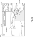
- graphics may be displayed in a picture-in-picture arrangement such as is shown by the camera feed data 104 in FIG. 1B .
- the GUI 100 of FIG. 1B is disclosed with replaced graphics.
- the graphics of FIG. 1A may be automatically or manually replaced by other graphics (e.g., camera feed data 104).
- Automatic replacement may include, but is not limited to, changing the graphics of the GUI 100 based on flight data.
- Manual replacement may include, but is not limited to, a user-directed change of what is displayed based on user input (e.g., touch on a touchscreen). Such replacement may be a replacement of a full-screen graphic as shown, but may also be a replacement of a smaller graphic (e.g., pop up window).
- An example of camera feed data is any camera feed of a location.
- a location may be a point of interest (POI).
- POI point of interest
- the POI may be defined as any interesting external location such as landmarks, or the destination or near destination (e.g., airport to be landed at, city of the airport, city that is near the airport, the last 10 miles approaching the airport, or the like).
- the camera feed data may be an externally-facing camera of the user's own aircraft pointed at or near the city of the airport to be landed at.
- the GUI 100 of FIG. 1C is disclosed with an image graphic 106 to be automatically displayed.
- World Guide images are manually displayed by the user.
- the image graphic 106 may be one or more images shown and stored on a memory of the computing device or received.
- the one or more images may be images of the POIs (e.g., stock photos, and the like).
- the image graphic 106 is configured to be automatically displayed in lieu of the camera feed data 104.
- the image graphic 106 may be displayed when the camera feed data 104 is unavailable, undesirable unaesthetic weather (e.g., raining), unexpected camera settings (e.g., undesired zoom setting or camera angle not showing the POI well), and/or low visibility (e.g., dark outside, night time).
- the image graphic 106 may include POI Airshow World Guide (WG) images as shown in FIG. 1D .
- WG POI Airshow World Guide
- flight data graphic 202 to be automatically displayed or replaced.
- flight data graphic 202 must be manually displayed or replaced by a user.
- flight data graphic 202 includes flight data such as time to destination 204, local time 206, altitude 208, ground speed 210, and distance traveled 212.
- the flight data may be received by the computing device.
- the flight data may be received via an aircraft network.
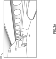
- the aircraft cabin 300 may include one or more lights 302. Note that a brighter intensity of the lights is shown as a darker shade for illustration purposes only.
- the cabin lighting level of the lights 302 may be automatically adjusted to any cabin lighting level indicative of a brightness.
- the cabin lighting level in FIG. 3A is set to off (e.g., set to value 0)
- the cabin lighting level in FIG. 3B is set to low (e.g., set to value 25)
- the cabin lighting level in FIG. 3C is set to medium (e.g., set to value 50)
- the cabin lighting level in FIG. 3D is set to maximum (e.g., set to value 100 out of 100).
- the label 100 in FIGS. 3A - 3D may, in some embodiments, be considered to be the computing device (e.g., a mobile touchscreen computing device).
- window levels e.g., window shade levels
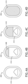
- the aircraft cabin 300 may include one or more window shades 408, 410, 412 configured to selectively block a portion of external light 414 from an external environment outside the aircraft.
- window levels may be any adjustment of shade of the windows 400, 402, 404, 406 such as via mechanical raising or lowering of window shades or electrochromic tinting of windows 400, 402, 404, 406 configured to be tinted.
- the window level of the windows 400, 402, 404, 406 may be automatically adjusted to any window level indicative of an amount of shade.
- the cabin lighting level in FIG. 4A is set to no shade (e.g., set to value 0)
- the window level in FIG. 4B is set to low (e.g., set to value 25)
- the window level in FIG. 4C is set to medium (e.g., set to value 50)
- the window level in FIG. 4D is set to maximum (e.g., set to value 100 out of 100).
- each value described herein may be a percentage (e.g., percentage of up to plus or minus a value of 12.5 from stated values) of the full range of possible values of each cabin feature.
- FIGS. 1A - 4D various embodiments are described.
- the computing device is configured to receive the flight data and the camera feed data. For example, such data may be continuously sent to the computing device via an external controller such as the aircraft network.
- the computing device determines whether to display the camera feed data 104 on the GUI 100 based on the flight data. For example, such a determination may be based on a proximity to a POI.
- the proximity may be time and/or distance based and may be based on the flight data.
- the proximity may include, or be based on (e.g., derived from), a time to destination 204 and/or a distance traveled 212.
- a camera feed of the POI may be automatically displayed to the user without them needing to keep watch or perform an action.
- a user may wish to see a destination city or landmark as it is approached and by automatically displaying the POI, the user may be able to abstain from constantly keeping track of the current location relative to the POI for purposes of avoiding missing the view, thereby increasing enjoyment of the flight.
- the graphics displayed on the GUI 100 may change for each flight path and/or leg of a flight.
- the GUI 100 may display a different POI (e.g., displayed as a stock image or as a live camera feed data 104) as the POI is being flown over.
- the computing device displays the camera feed data 104 on the GUI 100 based on the determination above. For example, if a certain proximity threshold is crossed or met, then the camera feed data 104 may be configured to be superimposed (e.g., picture-in-picture) on a graphic and/or replace a graphic. For instance, any time (e.g., less than 2 minutes to POI) or distance threshold (e.g., less than 5 kilometers from POI) may be used.
- any time e.g., less than 2 minutes to POI
- distance threshold e.g., less than 5 kilometers from POI
- the computing device directs automatic adjustments of cabin features to be performed.
- the computing device may transmit a signal of data (e.g., via wired and/or wireless protocol) indicative of an action to be performed, such as to actuate a window shade or dim a light.
- a direction may be based on a set of rules and/or threshold values associated with the flight data (e.g., local time).
- cabin features may be automatically adjusted based on the flight data, increasing comfortability of passengers.
- the directing may include adjusting the cabin lighting level to be at or around 50% (e.g., between 30 to 70%) and/or the window level to be at or around 25% (e.g., between 5 to 45%).
- the directing may include adjusting the cabin lighting level to be at or around 25% and/or the window level to be at or around 50%.
- the directing may include adjusting the cabin lighting level to be at or around 50% (e.g., between 30 to 70%) and/or the window level to be at or around 25% (e.g., between 5 to 45%).
- the directing may include adjusting the cabin lighting level to be at or around 100% (e.g., between 80 to 100%) and/or the window level to be at or around 0% (e.g., less than 20%).
- the directing may include adjusting the cabin lighting level to be at or around 25% and/or the window level to be at or around 100%.
- the aircraft cabin may be a private jet aircraft cabin and/or a business class aircraft cabin.
- embodiments of the methods disclosed herein may include one or more of the steps described herein. Further, such steps may be carried out in any desired order and two or more of the steps may be carried out simultaneously with one another. Two or more of the steps disclosed herein may be combined in a single step, and in some embodiments, one or more of the steps may be carried out as two or more sub-steps. Further, other steps or sub-steps may be carried in addition to, or as substitutes to one or more of the steps disclosed herein.
Landscapes
- Engineering & Computer Science (AREA)
- Aviation & Aerospace Engineering (AREA)
- Traffic Control Systems (AREA)
- User Interface Of Digital Computer (AREA)
Abstract
Description
- The present application claims the benefit of
India Provisional Patent Application 202211067639, filed November 24, 2022, titled SYSTEM AND METHOD FOR CONTROL OF CABIN WITH INTERNET OF THINGS (IOT) CONCEPT, naming Gopal Rudra Raju, Rathan Natarajan, Dhanuja H M, and Lakshmikanth GR - Embodiments of the inventive concepts disclosed herein are directed generally to aircraft cabin systems and, more particularly, to automatic control of cabin systems, such as cabin systems used in business jets or private jets.
- Cabin management systems (CMSs) provide passengers with convenient access to cabin controls (e.g., cabin lighting and climate settings, window shade controls) while providing the cabin crew with set-up and maintenance functionality. CMS controls are often used in business and/or private jet cabin systems. CMS controls may include a graphical user interface (GUI) and are generally hierarchical and textual menu-based systems. Typically, users are required to manually switch to airshow or camera sources to acquire and watch information about Points of Interest (POI). Further, lights and shades are manually adjustable via the GUI or mechanically. It may generally be difficult to determine what lighting or shade level or graphic/view/camera a user may desire at any particular moment.
- Therefore, it would be advantageous to provide a system that cures the shortcomings described above.
- A cabin management control device is disclosed for automating cabin features (e.g., shades, lights) and/or a GUI based on flight data, in accordance with one or more embodiments of the present disclosure. The cabin management control device may include a computing device having a touchscreen. The computing device may be in communication with an aircraft network and cabin controller. The computing device may be configured to display a graphical user interface (GUI) configured to control cabin features. The computing device may be configured to: receive flight data; receive camera feed data; determine whether to display the camera feed data based on the flight data; and direct, based on the flight data, an automatic adjustment of the cabin features. The cabin features may include at least one of: a window level of one or more window shades; or a cabin lighting level of one or more lights.
- This Summary is provided solely as an introduction to subject matter that is fully described in the Detailed Description and Drawings. The Summary should not be considered to describe essential features nor be used to determine the scope of the Claims. Moreover, it is to be understood that both the foregoing Summary and the following Detailed Description are example and explanatory only and are not necessarily restrictive of the subject matter claimed.
- The detailed description is described with reference to the accompanying figures. The use of the same reference numbers in different instances in the description and the figures may indicate similar or identical items. Various embodiments or examples ("examples") of the present disclosure are disclosed in the following detailed description and the accompanying drawings. The drawings are not necessarily to scale. In general, operations of disclosed processes may be performed in an arbitrary order, unless otherwise provided in the claims.
-
FIG. 1A is an illustration of a graphical user interface (GUI), in accordance with example embodiments of this disclosure. -
FIG. 1B is an illustration of the GUI ofFIG. 1A , in accordance with example embodiments of this disclosure. -
FIG. 1C is an illustration of the GUI ofFIG. 1B , in accordance with example embodiments of this disclosure. -
FIG. 1D is an illustration of the GUI ofFIG. 1C , in accordance with example embodiments of this disclosure. -
FIG. 2 is an illustration of the GUI ofFIG. 1D , in accordance with example embodiments of this disclosure. -
FIG. 3A is a schematic illustration of an aircraft cabin, in accordance with example embodiments of this disclosure. -
FIG. 3B is a schematic illustration of the aircraft cabin ofFIG. 3A with increased lighting, in accordance with example embodiments of this disclosure. -
FIG. 3C is a schematic illustration of the aircraft cabin ofFIG. 3B with increased lighting, in accordance with example embodiments of this disclosure. -
FIG. 3D is a schematic illustration of the aircraft cabin ofFIG. 3C with increased lighting, in accordance with example embodiments of this disclosure. -
FIG. 4A is a schematic illustration of a window, in accordance with example embodiments of this disclosure. -
FIG. 4B is a schematic illustration of the window ofFIG. 4A with a shade, in accordance with example embodiments of this disclosure. -
FIG. 4C is a schematic illustration of the window ofFIG. 4B with the shade lowered, in accordance with example embodiments of this disclosure. -
FIG. 4D is a schematic illustration of the window ofFIG. 4C with the shade completely lowered, in accordance with example embodiments of this disclosure. - Before explaining one or more embodiments of the disclosure in detail, it is to be understood that the embodiments are not limited in their application to the details of construction and the arrangement of the components or steps or methodologies set forth in the following description or illustrated in the drawings. In the following detailed description of embodiments, numerous specific details may be set forth in order to provide a more thorough understanding of the disclosure. However, it will be apparent to one of ordinary skill in the art having the benefit of the instant disclosure that the embodiments disclosed herein may be practiced without some of these specific details. In other instances, well-known features may not be described in detail to avoid unnecessarily complicating the instant disclosure.
- As used herein a letter following a reference numeral is intended to reference an embodiment of the feature or element that may be similar, but not necessarily identical, to a previously described element or feature bearing the same reference numeral (e.g., 1, 1a, 1b). Such shorthand notations are used for purposes of convenience only and should not be construed to limit the disclosure in any way unless expressly stated to the contrary.
- Further, unless expressly stated to the contrary, "or" refers to an inclusive or and not to an exclusive or. For example, a condition A or B is satisfied by any one of the following: A is true (or present) and B is false (or not present), A is false (or not present) and B is true (or present), and both A and B are true (or present).
- In addition, use of "a" or "an" may be employed to describe elements and components of embodiments disclosed herein. This is done merely for convenience and "a" and "an" are intended to include "one" or "at least one," and the singular also includes the plural unless it is obvious that it is meant otherwise.
- Finally, as used herein any reference to "in embodiments, "one embodiment" or "some embodiments" means that a particular element, feature, structure, or characteristic described in connection with the embodiment is included in at least one embodiment disclosed herein. The appearances of the phrase "in some embodiments" in various places in the specification are not necessarily all referring to the same embodiment, and embodiments may include one or more of the features expressly described or inherently present herein, or any combination or sub-combination of two or more such features, along with any other features which may not necessarily be expressly described or inherently present in the instant disclosure.
- Broadly speaking, embodiments of the inventive concepts disclosed herein are directed to an automated control scheme for cabin features (e.g., lights, shades) and/or graphics shown to a user on a graphical user interface (GUI). Such automation may be based on, for example, flight data parameters already known to a cabin management control device-thereby allowing for a solution that doesn't additional sensors or data collection. Such embodiments may be lower cost than other solutions, such as solutions requiring additional light sensors.
- In other cabin systems, cabin features and graphics may need to be manually adjusted by a user. For example, a cabin management control device with manual control of cabin lighting levels, window shade levels, and in-flight entertainment displayed on a GUI is disclosed in
U.S. Patent Application No. 16/657,231, filed October 18, 2019 U.S. Patent Application No. 16/657,231 may be utilized with an embodiment herein. For instance, the automated adjustment of lights, shades, and display of camera feed data of the present disclosure may also be simultaneously manually adjustable (e.g., capable of being overrode by manual user interaction with the GUI) in accordance with, but not limited to, manual user interactions described inU.S. Patent Application No. 16/657,231 . - Referring to
FIG. 1A , a graphical user interface (GUI) 100 is disclosed. In embodiments, theGUI 100 may be configured to display various graphics, graphical windows, camera feeds, photos, cabin feature controllable parameters (e.g., window shade and light controls and the like), and/or the like. Such graphics are configured to be at least one of automatically displayed or replaced according to embodiments herein. - For example, a
graphical representation 102 of a flight may be displayed as shown inFIG. 1A . For instance, thegraphical representation 102 may be referred to as an Airshow Flight Preview and provide a user with awareness of a time and/or distance of their flight. - Although not shown in
FIG. 1A , theGUI 100 may provide the user with controls for a variety of lighting or display elements throughout the cabin. TheGUI 100 may display a control interface to control the deployment of shades over one or more cabin windows. For example, and shown inFIG. 1 ofU.S. Patent Application No. 16/657,231 , a control interface may be displayed by theGUI 100 when the user selects (e.g., by tapping or touching), for instance, cabin lighting related controls. - In embodiments, the
GUI 100 may be displayed on any computing device including a touchscreen (i.e., a touch-sensitive display surface capable of accepting directed control input provided by a user by making contact with a particular location relative to the display surface, e.g., by tapping, pressing for an extended length of time, or directing a finger or stylus along the surface of the screen in a predetermined path) and in communication with networks or controller devices/systems aboard the aircraft. For example, theGUI 100 may be displayed on an interactive panel mounted to a wall, monument, or class divider within the aircraft cabin. Similarly, theGUI 100 may be displayed on a mobile computing device (e.g., a tablet). For example, users (e.g., passengers and crewmembers) may bring a compatible mobile computing device aboard the aircraft and "log in" to theGUI 100, enabling the users to view the GUI and control cabin functions through the touchscreen of the mobile device. In some embodiments, the tablet may connect wirelessly to aircraft-based networks (e.g., via Wi-Fi, Bluetooth, or any appropriate wireless communication protocols) allowing connectivity and remote control of cabin lighting, windows, in-flight entertainment (IFE) systems, and other cabin features. In some embodiments, the tablet may be physically connected to aircraft networks and cabin features via Ethernet connection (or any appropriate avionics networking connection). For example, the tablet may be mounted in a cradle configured to secure the device proximate to the user (e.g., proximate to a passenger seat occupied by the user) and providing an Ethernet interface via which the tablet may be physically connected to the networks. - In embodiments, the
GUI 100 may include other graphics. For example, additional graphics may be graphic windows (e.g., pop up graphics and the like) and replace the previously displayed graphics and/or be displayed along with (e.g., superimposed over) the previously/currently displayed graphics. In this regard, theGUI 100 may display superimposed graphics over the graphics shown byFIG. 1A . - Referring to
FIG. 1B , theGUI 100 ofFIG. 1A is disclosed with additional superimposed graphics. - An example of superimposed graphics is shown by
camera feed data 104 andflight data graphics 108. In embodiments, graphics may be displayed in a picture-in-picture arrangement such as is shown by thecamera feed data 104 inFIG. 1B . - Referring to
FIG. 1C , theGUI 100 ofFIG. 1B is disclosed with replaced graphics. For example, the graphics ofFIG. 1A may be automatically or manually replaced by other graphics (e.g., camera feed data 104). Automatic replacement may include, but is not limited to, changing the graphics of theGUI 100 based on flight data. Manual replacement may include, but is not limited to, a user-directed change of what is displayed based on user input (e.g., touch on a touchscreen). Such replacement may be a replacement of a full-screen graphic as shown, but may also be a replacement of a smaller graphic (e.g., pop up window). - An example of camera feed data is any camera feed of a location. For example, a location may be a point of interest (POI). For instance, the POI may be defined as any interesting external location such as landmarks, or the destination or near destination (e.g., airport to be landed at, city of the airport, city that is near the airport, the last 10 miles approaching the airport, or the like). For example, the camera feed data may be an externally-facing camera of the user's own aircraft pointed at or near the city of the airport to be landed at.
- Referring to
FIG. 1D , theGUI 100 ofFIG. 1C is disclosed with an image graphic 106 to be automatically displayed. Typically, World Guide images are manually displayed by the user. For example, the image graphic 106 may be one or more images shown and stored on a memory of the computing device or received. For instance, the one or more images may be images of the POIs (e.g., stock photos, and the like). In embodiments, the image graphic 106 is configured to be automatically displayed in lieu of thecamera feed data 104. For example, the image graphic 106 may be displayed when thecamera feed data 104 is unavailable, undesirable unaesthetic weather (e.g., raining), unexpected camera settings (e.g., undesired zoom setting or camera angle not showing the POI well), and/or low visibility (e.g., dark outside, night time). In examples, the image graphic 106 may include POI Airshow World Guide (WG) images as shown inFIG. 1D . - Referring to
FIG. 2 , theGUI 100 ofFIG. 1D is disclosed with flight data graphic 202 to be automatically displayed or replaced. Typically, flight data graphic 202 must be manually displayed or replaced by a user. - In embodiments, flight data graphic 202 includes flight data such as time to
destination 204,local time 206,altitude 208,ground speed 210, and distance traveled 212. The flight data may be received by the computing device. For example, the flight data may be received via an aircraft network. - Referring to
FIGS. 3A - 3D , anaircraft cabin 300 with various adjustments to cabin lighting levels are disclosed. Theaircraft cabin 300 may include one ormore lights 302. Note that a brighter intensity of the lights is shown as a darker shade for illustration purposes only. - In embodiments, the cabin lighting level of the
lights 302 may be automatically adjusted to any cabin lighting level indicative of a brightness. For example, the cabin lighting level inFIG. 3A is set to off (e.g., set to value 0), the cabin lighting level inFIG. 3B is set to low (e.g., set to value 25), the cabin lighting level inFIG. 3C is set to medium (e.g., set to value 50), and the cabin lighting level inFIG. 3D is set to maximum (e.g., set to value 100 out of 100). - Note that the
label 100 inFIGS. 3A - 3D may, in some embodiments, be considered to be the computing device (e.g., a mobile touchscreen computing device). - Referring to
FIGS. 4A - 4D ,windows aircraft cabin 300 may include one or more window shades 408, 410, 412 configured to selectively block a portion of external light 414 from an external environment outside the aircraft. In embodiments, window levels may be any adjustment of shade of thewindows windows - In embodiments, the window level of the
windows FIG. 4A is set to no shade (e.g., set to value 0), the window level inFIG. 4B is set to low (e.g., set to value 25), the window level inFIG. 4C is set to medium (e.g., set to value 50), and the window level inFIG. 4D is set to maximum (e.g., set to value 100 out of 100). For instance, each value described herein may be a percentage (e.g., percentage of up to plus or minus a value of 12.5 from stated values) of the full range of possible values of each cabin feature. - Referring to
FIGS. 1A - 4D , various embodiments are described. - In embodiments, the computing device is configured to receive the flight data and the camera feed data. For example, such data may be continuously sent to the computing device via an external controller such as the aircraft network.
- In embodiments, the computing device determines whether to display the
camera feed data 104 on theGUI 100 based on the flight data. For example, such a determination may be based on a proximity to a POI. For instance, the proximity may be time and/or distance based and may be based on the flight data. For example, the proximity may include, or be based on (e.g., derived from), a time todestination 204 and/or a distance traveled 212. In this regard, a camera feed of the POI may be automatically displayed to the user without them needing to keep watch or perform an action. For example, a user may wish to see a destination city or landmark as it is approached and by automatically displaying the POI, the user may be able to abstain from constantly keeping track of the current location relative to the POI for purposes of avoiding missing the view, thereby increasing enjoyment of the flight. - For example, in embodiments, the graphics displayed on the
GUI 100 may change for each flight path and/or leg of a flight. For example, multiple times during a flight, theGUI 100 may display a different POI (e.g., displayed as a stock image or as a live camera feed data 104) as the POI is being flown over. - In embodiments, the computing device displays the
camera feed data 104 on theGUI 100 based on the determination above. For example, if a certain proximity threshold is crossed or met, then thecamera feed data 104 may be configured to be superimposed (e.g., picture-in-picture) on a graphic and/or replace a graphic. For instance, any time (e.g., less than 2 minutes to POI) or distance threshold (e.g., less than 5 kilometers from POI) may be used. - In embodiments, the computing device directs automatic adjustments of cabin features to be performed. For example, the computing device may transmit a signal of data (e.g., via wired and/or wireless protocol) indicative of an action to be performed, such as to actuate a window shade or dim a light. Further, such a direction may be based on a set of rules and/or threshold values associated with the flight data (e.g., local time). In this regard, cabin features may be automatically adjusted based on the flight data, increasing comfortability of passengers.
- For example, below are various nonlimiting example sets of rules that may be used, each rule used alone and/or in combination with any other rules or flight data described or not described, in accordance with one or more embodiments herein. For purposes of these rules:


- In embodiments, when altitude is at least 30,000 feet, local time is greater than Duration1, and local time is less than Duration2, then the directing may include adjusting the cabin lighting level to be at or around 50% (e.g., between 30 to 70%) and/or the window level to be at or around 25% (e.g., between 5 to 45%).
- In embodiments, when altitude is at least 30,000 feet, local time is greater than Duration2, and local time is less than Duration3, then the directing may include adjusting the cabin lighting level to be at or around 25% and/or the window level to be at or around 50%.
- In embodiments, when altitude is at least 30,000 feet, local time is greater than Duration3, and local time is less than local sunset time, then the directing may include adjusting the cabin lighting level to be at or around 50% (e.g., between 30 to 70%) and/or the window level to be at or around 25% (e.g., between 5 to 45%).
- In embodiments, when altitude is at least 30,000 feet, local time is greater than local sunset time, and local time is less than local sunset time plus DLD, then the directing may include adjusting the cabin lighting level to be at or around 100% (e.g., between 80 to 100%) and/or the window level to be at or around 0% (e.g., less than 20%).
- In embodiments, when altitude is at least 30,000 feet, local time is greater than local sunset time plus DLD, and local time is less than local sunrise time of the next day, then the directing may include adjusting the cabin lighting level to be at or around 25% and/or the window level to be at or around 100%.
- In embodiments, the aircraft cabin may be a private jet aircraft cabin and/or a business class aircraft cabin.
- It is to be understood that embodiments of the methods disclosed herein may include one or more of the steps described herein. Further, such steps may be carried out in any desired order and two or more of the steps may be carried out simultaneously with one another. Two or more of the steps disclosed herein may be combined in a single step, and in some embodiments, one or more of the steps may be carried out as two or more sub-steps. Further, other steps or sub-steps may be carried in addition to, or as substitutes to one or more of the steps disclosed herein.
- Although inventive concepts have been described with reference to the embodiments illustrated in the attached drawing figures, equivalents may be employed and substitutions made herein without departing from the scope of the claims. Components illustrated and described herein are merely examples of a system/device and components that may be used to implement embodiments of the inventive concepts and may be replaced with other devices and components without departing from the scope of the claims. Furthermore, any dimensions, degrees, and/or numerical ranges provided herein are to be understood as non-limiting examples unless otherwise specified in the claims.
Claims (15)
- A cabin management control device, comprising:a computing device comprising a touchscreen, the computing device including at least one processor and in communication with at least one of an aircraft network and a cabin controller, the computing device configured to display via the touchscreen at least one graphical user interface (GUI) configured to control cabin features corresponding to an aircraft cabin,wherein the computing device is configured to:receive flight data;receive camera feed data;determine whether to display the camera feed data on the GUI based on the flight data;display the camera feed data on the GUI based on the determining; anddirect, based on the flight data, an automatic adjustment of the cabin features, wherein the cabin features include at least one of:a window level of one or more window shades; ora cabin lighting level of one or more lights.
- The cabin management control device of claim 1, wherein the camera feed data is a camera feed of a point of interest (POI) related to a flight path.
- The cabin management control device of claim 2, wherein the determining whether to display the camera feed data is based on a proximity to the POI, wherein the proximity is based on the flight data.
- The cabin management control device of any preceding claim, wherein the flight data comprises local time.
- The cabin management control device of claim 4, wherein the automatic adjustment of the window level is based on the local time.
- The cabin management control device of claim 5, wherein the automatic adjustment of the window level is further based on a local sunrise time and a local sunset time.
- The cabin management control device of claim 6, wherein the automatic adjustment of the window level includes lowering the window level based on the local time being greater than the local sunset time.
- The cabin management control device of claim 5, wherein the automatic adjustment of the window level or the window level is further based on an altitude of the flight data, and optionally wherein the automatic adjustment of the window level is further based on the altitude being at least 30,000 feet.
- The cabin management control device of claim 4, wherein the automatic adjustment of the cabin lighting level is based on the local time.
- The cabin management control device of claim 9, wherein the automatic adjustment of the cabin lighting level is further based on a local sunrise time and a local sunset time, and optionally wherein the automatic adjustment of the cabin lighting level includes lowering the cabin lighting level based on the local time being greater than the local sunset time.
- The cabin management control device of claim 9, wherein the automatic adjustment of the cabin lighting level or the cabin lighting level is further based on an altitude of the flight data, and optionally wherein the automatic adjustment of the cabin lighting level is further based on the altitude being at least 30,000 feet.
- The cabin management control device of any preceding claim, wherein the computing device is configured to be mounted within the aircraft cabin, and optionally wherein:
the computing device is configured to be mounted proximate to a passenger seat. - The cabin management control device of any preceding claim, wherein the computing device includes a mobile computing device.
- The cabin management control device of claim 13, wherein the mobile computing device is wirelessly coupled to the aircraft network and the cabin controller, or , wherein the mobile computing device is physically coupled to the aircraft network and the cabin controller.
- The cabin management control device of any preceding claim, wherein:the aircraft cabin includes a passenger cabin;wherein a visible parameter of the GUI corresponds to at least one of the cabin lighting level, the window level, or a graphic capable of being displayed.
Applications Claiming Priority (2)
| Application Number | Priority Date | Filing Date | Title |
|---|---|---|---|
| IN202211067639 | 2022-11-24 | ||
| US18/212,583 US20240174362A1 (en) | 2022-11-24 | 2023-06-21 | System and method for control of cabin with internet of things (iot) concept |
Publications (2)
| Publication Number | Publication Date |
|---|---|
| EP4375187A1 true EP4375187A1 (en) | 2024-05-29 |
| EP4375187B1 EP4375187B1 (en) | 2025-12-31 |
Family
ID=88837373
Family Applications (1)
| Application Number | Title | Priority Date | Filing Date |
|---|---|---|---|
| EP23210409.1A Active EP4375187B1 (en) | 2022-11-24 | 2023-11-16 | SYSTEM AND METHOD FOR CONTROLLING A CABIN WITH AN INTERNET OF THINGS (IoT) CONCEPT |
Country Status (1)
| Country | Link |
|---|---|
| EP (1) | EP4375187B1 (en) |
Citations (4)
| Publication number | Priority date | Publication date | Assignee | Title |
|---|---|---|---|---|
| US20160004374A1 (en) * | 2014-03-11 | 2016-01-07 | Cessna Aircraft Company | User Interface For An Aircraft |
| EP3470327A1 (en) * | 2017-10-16 | 2019-04-17 | The Boeing Company | Interactive dimmable window systems and methods |
| US20210122469A1 (en) * | 2019-10-24 | 2021-04-29 | Panasonic Avionics Corporatiom | Systems and methods for providing a wake-up user interface for a night mode on transportation vehicles |
| US11182970B1 (en) * | 2019-12-09 | 2021-11-23 | Rockwell Collins, Inc. | Augmented reality aircraft window and method |
-
2023
- 2023-11-16 EP EP23210409.1A patent/EP4375187B1/en active Active
Patent Citations (4)
| Publication number | Priority date | Publication date | Assignee | Title |
|---|---|---|---|---|
| US20160004374A1 (en) * | 2014-03-11 | 2016-01-07 | Cessna Aircraft Company | User Interface For An Aircraft |
| EP3470327A1 (en) * | 2017-10-16 | 2019-04-17 | The Boeing Company | Interactive dimmable window systems and methods |
| US20210122469A1 (en) * | 2019-10-24 | 2021-04-29 | Panasonic Avionics Corporatiom | Systems and methods for providing a wake-up user interface for a night mode on transportation vehicles |
| US11182970B1 (en) * | 2019-12-09 | 2021-11-23 | Rockwell Collins, Inc. | Augmented reality aircraft window and method |
Also Published As
| Publication number | Publication date |
|---|---|
| EP4375187B1 (en) | 2025-12-31 |
Similar Documents
| Publication | Publication Date | Title |
|---|---|---|
| EP2851281B1 (en) | System and method for interactive visualization of information in an aircraft cabin | |
| US10540007B2 (en) | Systems and methods for delivering imagery to head-worn display systems | |
| US20120325962A1 (en) | Window-less transport aircraft | |
| US9424756B2 (en) | Visual flight rules approach to airports | |
| US10464674B2 (en) | Interactive sidewall display system and method | |
| US9407826B1 (en) | System for and method of adjusting a vision system | |
| US9555896B2 (en) | Aircraft flight control | |
| EP3470327B1 (en) | Interactive dimmable window systems and methods | |
| US12282650B2 (en) | Hypercontextual touch-the-plane (TTP) cabin management graphical user interface (GUI) | |
| US11304161B2 (en) | Systems and methods for synchronizing multiple control devices with a movable object | |
| EP3786932B1 (en) | Extending brightness dimming range of displays via image frame manipulation | |
| KR20190061863A (en) | System for providing service education-training of air traffic control based on virtual reality | |
| EP4375187B1 (en) | SYSTEM AND METHOD FOR CONTROLLING A CABIN WITH AN INTERNET OF THINGS (IoT) CONCEPT | |
| US20240174362A1 (en) | System and method for control of cabin with internet of things (iot) concept | |
| CN113341603A (en) | Intelligent ambient light control system and control method based on intelligent glass | |
| JP7289432B2 (en) | Flight route setting system | |
| CN114228973B (en) | Aircraft porthole system with transparent display and display method and medium thereof | |
| EP4506930A1 (en) | Efvs integrated interface for image display control | |
| FR3016448A1 (en) | AIRCRAFT INFORMATION DISPLAY SYSTEM AND ASSOCIATED METHOD | |
| DE102024133675A1 (en) | System and method for displaying an adaptive virtual sky in an aircraft cabin | |
| EP4166449B1 (en) | Vision based aircraft cabin ambient light control | |
| US20170054920A1 (en) | Aircraft camera viewing system | |
| CN102548085A (en) | Light adjusting device for overcoming time difference | |
| WO2017004660A1 (en) | A pilot flight reorientation arrangement | |
| EP3718906A1 (en) | Dynamic illumination system for airborne vehicles |
Legal Events
| Date | Code | Title | Description |
|---|---|---|---|
| PUAI | Public reference made under article 153(3) epc to a published international application that has entered the european phase |
Free format text: ORIGINAL CODE: 0009012 |
|
| STAA | Information on the status of an ep patent application or granted ep patent |
Free format text: STATUS: THE APPLICATION HAS BEEN PUBLISHED |
|
| AK | Designated contracting states |
Kind code of ref document: A1 Designated state(s): AL AT BE BG CH CY CZ DE DK EE ES FI FR GB GR HR HU IE IS IT LI LT LU LV MC ME MK MT NL NO PL PT RO RS SE SI SK SM TR |
|
| STAA | Information on the status of an ep patent application or granted ep patent |
Free format text: STATUS: REQUEST FOR EXAMINATION WAS MADE |
|
| 17P | Request for examination filed |
Effective date: 20241128 |
|
| RBV | Designated contracting states (corrected) |
Designated state(s): AL AT BE BG CH CY CZ DE DK EE ES FI FR GB GR HR HU IE IS IT LI LT LU LV MC ME MK MT NL NO PL PT RO RS SE SI SK SM TR |
|
| GRAP | Despatch of communication of intention to grant a patent |
Free format text: ORIGINAL CODE: EPIDOSNIGR1 |
|
| STAA | Information on the status of an ep patent application or granted ep patent |
Free format text: STATUS: GRANT OF PATENT IS INTENDED |
|
| INTG | Intention to grant announced |
Effective date: 20250825 |
|
| GRAS | Grant fee paid |
Free format text: ORIGINAL CODE: EPIDOSNIGR3 |
|
| GRAA | (expected) grant |
Free format text: ORIGINAL CODE: 0009210 |
|
| STAA | Information on the status of an ep patent application or granted ep patent |
Free format text: STATUS: THE PATENT HAS BEEN GRANTED |
|
| AK | Designated contracting states |
Kind code of ref document: B1 Designated state(s): AL AT BE BG CH CY CZ DE DK EE ES FI FR GB GR HR HU IE IS IT LI LT LU LV MC ME MK MT NL NO PL PT RO RS SE SI SK SM TR |
|
| REG | Reference to a national code |
Ref country code: CH Ref legal event code: F10 Free format text: ST27 STATUS EVENT CODE: U-0-0-F10-F00 (AS PROVIDED BY THE NATIONAL OFFICE) Effective date: 20251231 Ref country code: GB Ref legal event code: FG4D |
|
| REG | Reference to a national code |
Ref country code: DE Ref legal event code: R096 Ref document number: 602023010407 Country of ref document: DE |
|
| REG | Reference to a national code |
Ref country code: IE Ref legal event code: FG4D |
|
| REG | Reference to a national code |
Ref country code: LT Ref legal event code: MG9D |
|
| PG25 | Lapsed in a contracting state [announced via postgrant information from national office to epo] |
Ref country code: NO Free format text: LAPSE BECAUSE OF FAILURE TO SUBMIT A TRANSLATION OF THE DESCRIPTION OR TO PAY THE FEE WITHIN THE PRESCRIBED TIME-LIMIT Effective date: 20260331 |
|
| PG25 | Lapsed in a contracting state [announced via postgrant information from national office to epo] |
Ref country code: FI Free format text: LAPSE BECAUSE OF FAILURE TO SUBMIT A TRANSLATION OF THE DESCRIPTION OR TO PAY THE FEE WITHIN THE PRESCRIBED TIME-LIMIT Effective date: 20251231 Ref country code: HR Free format text: LAPSE BECAUSE OF FAILURE TO SUBMIT A TRANSLATION OF THE DESCRIPTION OR TO PAY THE FEE WITHIN THE PRESCRIBED TIME-LIMIT Effective date: 20251231 |
|
| PG25 | Lapsed in a contracting state [announced via postgrant information from national office to epo] |
Ref country code: RS Free format text: LAPSE BECAUSE OF FAILURE TO SUBMIT A TRANSLATION OF THE DESCRIPTION OR TO PAY THE FEE WITHIN THE PRESCRIBED TIME-LIMIT Effective date: 20260331 |
|
| PG25 | Lapsed in a contracting state [announced via postgrant information from national office to epo] |
Ref country code: LV Free format text: LAPSE BECAUSE OF FAILURE TO SUBMIT A TRANSLATION OF THE DESCRIPTION OR TO PAY THE FEE WITHIN THE PRESCRIBED TIME-LIMIT Effective date: 20251231 |
|
| PG25 | Lapsed in a contracting state [announced via postgrant information from national office to epo] |
Ref country code: BG Free format text: LAPSE BECAUSE OF FAILURE TO SUBMIT A TRANSLATION OF THE DESCRIPTION OR TO PAY THE FEE WITHIN THE PRESCRIBED TIME-LIMIT Effective date: 20251231 |
|
| REG | Reference to a national code |
Ref country code: NL Ref legal event code: MP Effective date: 20251231 |